

Page 1
π H-2812
DIGITAL
TIME CLOCK
1-80 0-295-5510
uline.com
SETUP
R
SU MO TU WE TH FR SA
15
AM
8
16
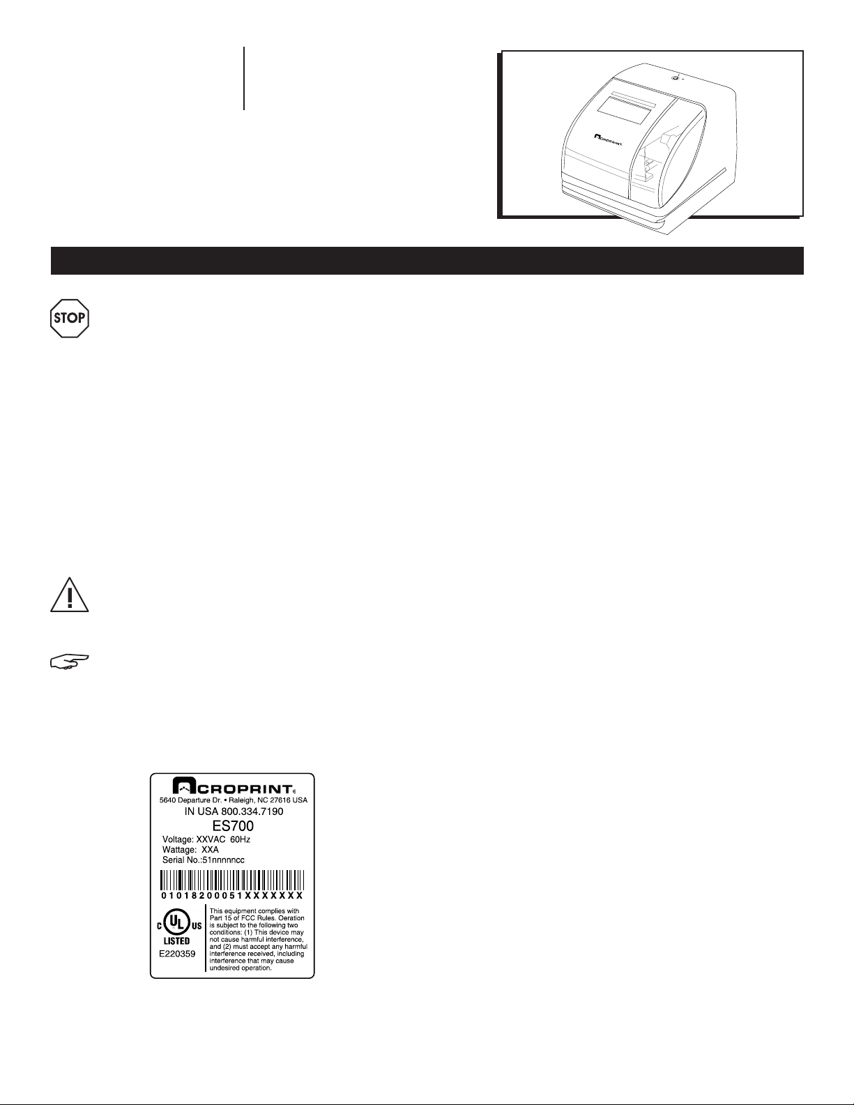
ES700
WARNING! This equipment has been tested
and found to comply with the limits for a
Class A digital device, pursuant to Part 15
of FCC Rules. These limits are designed
to provide reasonable protection against
harmful interference when the equipment is
operated in a commercial environment. This
equipment generates, uses and can radiate
radio frequency energy and, if not installed
and used in accordance with the instruction
manual, may cause harmful interference
to radio communications. Operation of this
equipment in a residential area is likely to
cause harmful interference in which case the
user will be required to correct the interference
at his or her own expense.
CAUTION! Changes or modifications not
expressly approved by the party responsible for
compliance could void the user’s authority to
operate the equipment.
NOTE: This digital apparatus does not exceed
the Class A limits for radio noise emissions
from digital apparatus as set out in the radio
interference regulations of the Canadian
Department of Communications.
Serial number label for bottom of clock.
TABLE OF CONTENTS
Alert Definitions .....................................................................2
Precautions ...........................................................................3
Introduction ..........................................................................4
Features ................................................................................4
Equipment ......................................................................... 4-5
ES700 .................................................................................. 4
Open and Close Unit .......................................................... 5
Power the Unit/Print Positioning ........................................... 5
Important Things to Remember When Using The ES700 .......6
Quick Start .............................................................................6
Atomic Synchronization ...................................................... 6
Set Time Zone (-5 EST, -6 CST, -7 MST, -8 PST) ....................... 6
Automatically Receive Atomic Signal ................................ 6
Turn DST OFF ........................................................................ 6
Program the Time Recorder .................................................. 7
Settings .............................................................................7-15
Time .....................................................................................7
Date .................................................................................... 8
12/24 Hour Format .............................................................. 8
Print Order ........................................................................... 9
Year Digit ............................................................................ 9
Hour/Minute ................................................................... 9-10
Leading Zero .................................................................... 10
Preset Comments .............................................................. 10
Language .......................................................................... 11
Print Length ........................................................................ 11
Print Method ................................................................. 11-12
Daylight Saving Time (DST) ............................................12-14
Set Password ................................................................. 14-15
Enter Password ...................................................................15
Cancel the Password .........................................................15
Reset Factory Default Settings ....................................... 15-16
Wall Mounting .....................................................................16
Replacing the Ribbon Cassette .......................................... 17
Troubleshooting ...................................................................18
Specifications .....................................................................19
Information contained in this manual is company private to Acroprint Time Recorder Co., and shall not be modified, used, copied, reproduced or disclosed in whole or in part
without the written consent of Acroprint. Contents herein are current as of the date of publication. Acroprint reserves the right to change the contents without prior notice. This
manual has been carefully prepared to cover all aspects of this unit. However, if any explanations are inadequate, unclear, or difficult to understand, please contact Acroprint.
We recommend that you carefully read this manual to maximize the use of this unit. © 2008 Acroprint Time Recorder Co. All Rights Reserved.
PAGE 1 OF 19 1015 IH-2812
Page 2

SETUP CONTINUED
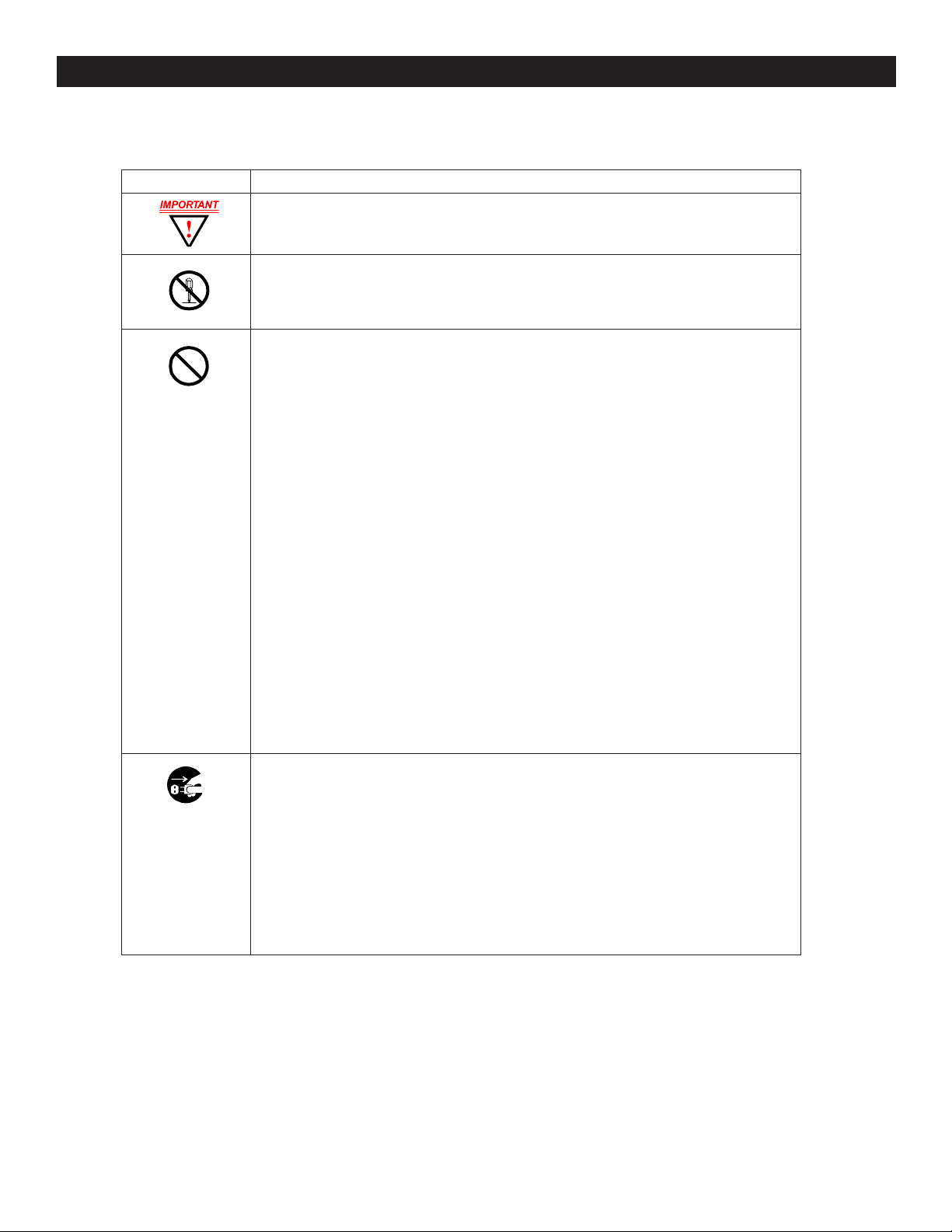
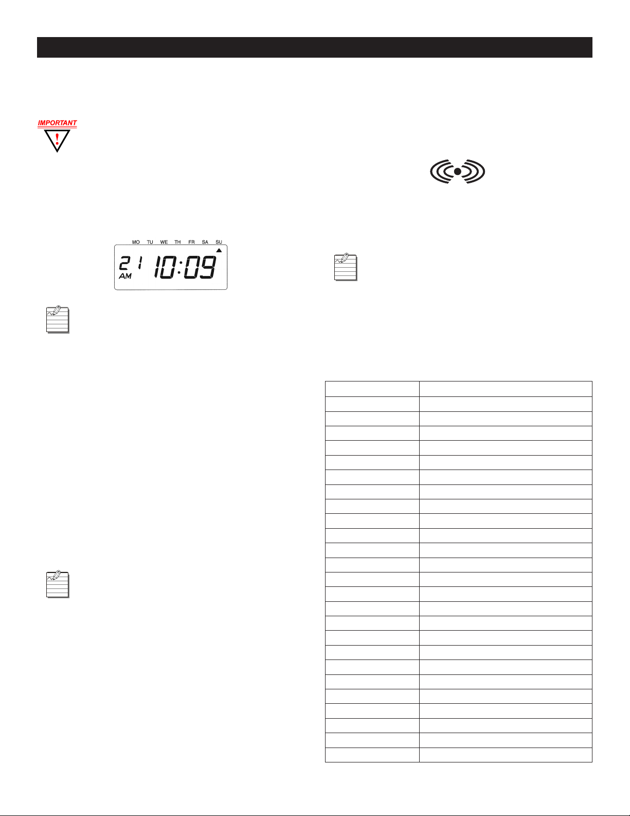
ALERT DEFINITIONS
For your safety and the protection of the unit, the following alerts are used throughout this manual.
READER ALERT MEANING
Alerts you to supplementary information.
Alerts you to helpful tips (information given as a guide to action).
Alerts you to supplementary information that is essential to the completion of a task.
Alerts you to possible data loss, breaches of security, or other more serious problems.
Alerts you that failure to take or avoid a specific action might result in physical harm to you
or to the hardware.
Alerts you to stop immediately. Failure to do so will result in physical harm to you or to the
hardware.
Alerts you that improper handling may cause electrical shock resulting in serious injury or
death.
Alerts you not to disassemble or modify the unit.
Alerts you to remove power cord from wall outlet
Alerts you "do not" perform an action.
PAGE 2 OF 19 1015 IH-2812
Page 3
PRECAUTIONS
ALERT DESCRIPTION
SETUP CONTINUED
• Insert the power plug as far as it will go. Improper insertion of the plug may result in fire or
electric shock.
• Do not disassemble the unit. High voltage is present inside that may lead to an
electric shock.
• Do not modify the unit. Modifications may cause a fire and/or electric shock.
• Do not use any voltage of the power source other than designated.
• Do not share a single outlet with another plug. This may lead to a fire or electric shock.
• Do not damage, break, or modify the power cord.
• Do not put heavy objects on, pull, or forcefully bend the cord. These may damage the
cord, possibly resulting in a fire or electric shock.
• Do not plug or unplug the unit with a wet hand. This may lead to an electric shock.
• Do not place the unit on an uneven or tilted surface. This may result in injuries due to the
unit dropping or falling off.
• Do not put a water-filled container or a metal object on top of the unit. If water is spilled
or the metallic object slips inside, a fire or electric shock may occur.
• Do not install the unit in a humid or dusty environment. This may result in a fire or
electric shock.
• Do not place the unit near a kitchen counter or humidifier. Oil, smoke, or steam
generating from them may cause fire or electric shock.
• Do not yank the power cord to disconnect from the outlet. Hold the plug with your hand
to do so, or the cord may be damaged. This may lead to a fire or electric shock.
• Do not insert or drop any other time card than specified into the slot. Such misuse may
cause a fire or electric shock.
• Do not come in contact with the print head. This may result in personal injury.
• If any anomaly occurs, for example, heat or smoke is generated or an odor is emitted,
unplug the unit immediately and contact your dealer for servicing. There is a danger
that further use may cause a fire or electric shock.
• If foreign matter should get in the unit (including a piece of metal, water, or liquid),
disconnect the plug from the outlet immediately and contact your dealer for servicing.
There is a danger that further use may cause a fire or electric shock.
• Remove the line cord plug from the outlet before transferring the unit, or it may damage
the cord. This may lead to a fire or electric shock.
• If the unit should be dropped or the case is broken, unplug the unit and contact your
dealer for servicing. Further use may lead to a fire or electric shock.
PAGE 3 OF 19 1015 IH-2812
Page 4
SETUP CONTINUED
INTRODUCTION
Thank you for purchasing an Acroprint Model ES700 Time Recorder. We are confident this unit will give you full
satisfaction. Items such as the time and date are preset at the factory. After plugging in the power cord to the wall
outlet, this unit can be used. However, we recommend reading this manual before you start using this unit.
FEATURES
Main Applications: Payroll/job cost recorder or time stamp.
• Atomic Synchronization sets time and date automatically
• Quartz Time Recorder
• Digital LCD (Date, Hour, Minute, Day of the Week)
• Perpetual Calendar
• Dot-Matrix Printer
• Automatic Daylight Saving Time (DST)
• Automatic Date, Month Year Change to 2099
• 3-way Print Activation:
a. Automatic
b. Semi-Automatic
• Durable Snap-in Ribbon Cartridge
• Adjustable Print Positions
• Prints in 4 languages
• Prints Date
• 13 Preset Comments
• Selectable 2- or 4-digit Year
• 12 or 24-Hour Format
• Regular Minute, Tenths, or Hundredths of an Hour
• Password Protection
• Wall or Desktop Mount
c. Manual
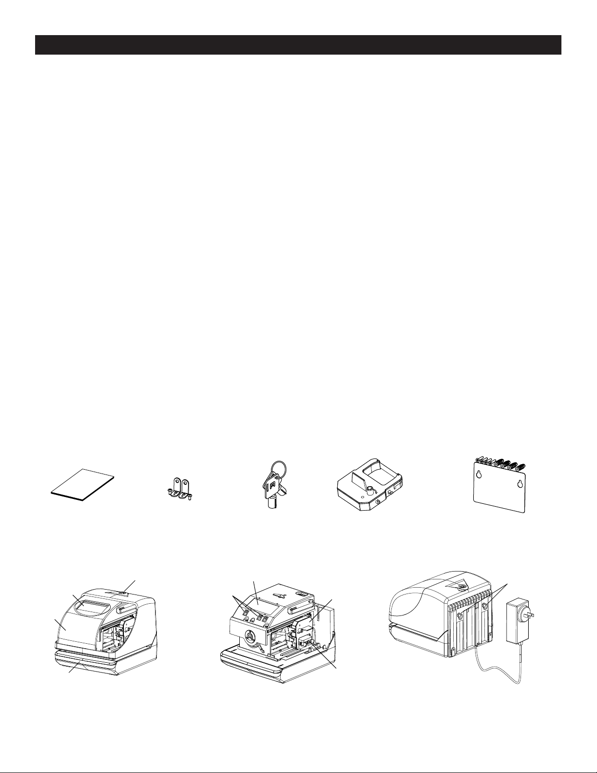
EQUIPMENT
Unpack the unit and check its contents to ensure that the time recorder unit and all accessories shown below are
included. If equipment has been damaged in transit, report the extent of damage to the transportation company
and to Acroprint. Order replacement equipment, if necessary.
ES700 Manual x 1
Display
Cover
Push Bar
Front View (With Cover) Front View (Without Cover) Back View
PAGE 4 OF 19 1015 IH-2812
Wall Bracket x 2
Key Hole
(2 Screws)
Control
Buttons
Keys x 2 Ribbon Cassette x 1
Display
(Factory Installed)
Ribbon
Cassette
Print Head
Wall-Mount Fitting x 1
(4 Screws, 4 Mollies, 1 Sheet)
Wall-Mount Holes
AC
Adapter
AC Adapter Cord
Page 5
SETUP CONTINUED
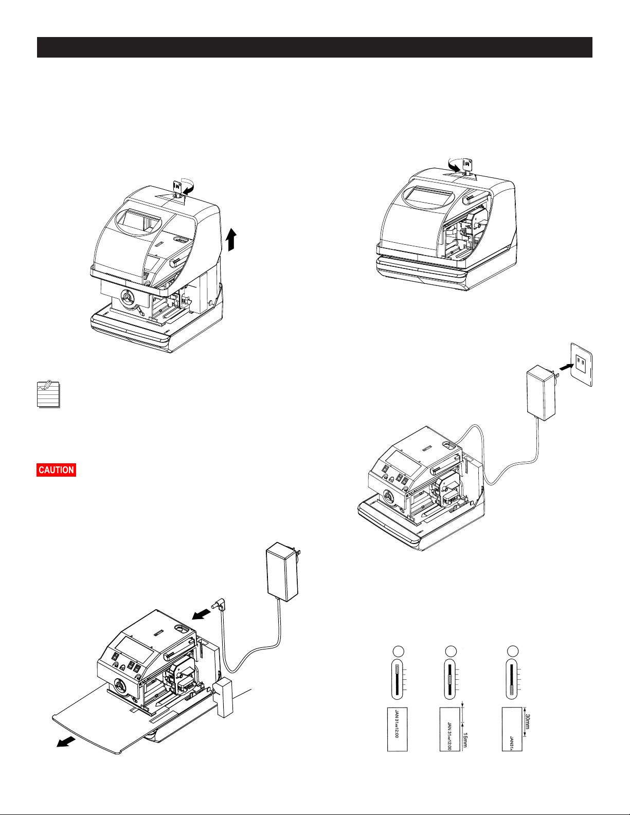
OPEN AND CLOSE UNIT
OPEN UNIT
1. Insert the key into the lock on cover of the unit. Turn
the key in the clockwise position to unlock the unit.
Remove the cover. (See Figure 1)
Figure 1
When you open the unit for the first time,
you must remove the Protective Pad and
Cardboard Insert. Plug the AC Adapter
into the back of the unit. Refer to Remove
Protective Pad and Cardboard Insert/Plug
AC Adapter into Unit below. (See Figure 2)
Open Unit
CLOSE UNIT
Replace the cover. Insert the key into the lock on the
cover of the unit. Turn the key in the counter-clockwise
position to lock the unit. Refer to Close Unit below.
(See Figure 3)
Figure 3
Close Unit
POWER THE UNIT/PRINT POSITIONING
Plug the transformer into the AC outlet.
Insert a card to get a sample print.
Refer to Power the Unit below.
(See Figure 4)
AC Adapter
Figure 4
AC Outlet
Ribbon may dislodge. To avoid damage to
the printer, press the ribbon cartridge firmly
into position after removing the protective pad.
Refer to Remove Protective Pad and Cardboard
Insert/Plug AC Adapter into Unit. (See Figure 2)
2. Remove protective pad and cardboard
insert. Plug AC adapter into unit.
(See Figure 2)
Figure 2
Cardboard
Insert
AC Adapter
Power the Unit
Print position from the card edge is adjustable by pressing
and sliding the print position button located on the right
outside bottom of the unit. Maximum distance from
edge of form to print is approximately 1⁄" (30 mm).
Refer to Print Position on Time Card below. (See Figure 5)
Figure 5
Protective
Pad
PAGE 5 OF 19 1015 IH-2812
Print Position on Time Card
Page 6
SETUP CONTINUED
IMPORTANT THINGS TO REMEMBER
WHEN USING THE ES700
You must open the unit to make changes
to the settings. After each use, replace the
cover and lock it. Refer to "Open and Close
Unit" on page 5.
After performing each procedure on the unit, remember
to press
mode. To exit program mode anytime, press
SET
until the unit returns to normal operation
SET
until the
unit returns to normal operation mode. (See Figure 6)
Figure 6
When you are setting a digit or an option on
the display, flashing means that it is ready to
be changed. You must press
SELECT
until you
reach the desired digit or option. Then press
SET
to lock the desired value in place.
Printing is always disabled while settings are being
changed. Once the final
SET
has been completed in
any given operation, printing is enabled.
QUICK START
ATOMIC SYNCHRONIZATION
The clock receives the NIST WWVB Signal, which will
automatically set the time and date. Refer to Atomic
Synchronization Time Zones to the right.
For more information about the WWVB Radio Signal
(Atomic Signal), visit NIST’s website at: www.nist.gov.
Daylight Saving Time (DST) defaults to AUTOMATIC.
If you are in the EST Time Zone and observe
DST, the Atomic Synchronization should work
automatically after the AC cord has been
plugged into the AC outlet overnight.
SET TIME ZONE (-5 EST, -6 CST, -7 MST, -8 PST)
1. Press
2. Press
3. Press
SELECT
CHANGE
until the arrow points to Time Zone.
until your Time Zone appears.
(See Time Zones on page 8.)
SET
.
AUTOMATICALLY RECEIVE ATOMIC SIGNAL
1. Plug the transformer into the AC outlet overnight.
2. If the Atomic Clock Symbol indicator (See Figure 7) is on
in the morning, your clock is receiving the atomic clock
signal and the time and date should be set properly.
Figure 7
Atomic Synchronization Symbol Indicator
3. If you did not receive the atomic signal, try
repositioning the clock or set the unit manually as
described above.
If you do not observe DST, follow the
procedure below to turn DST off.
TURN DST OFF
1. Press
2. Press
3. Press
ATOMIC SYNCHRONIZATION TIME ZONES (DEFAULT = ES-05)
DISPLAY TIME ZONE DESCRIPTION
SELECT
CHANGE
SET
12
11
10
09
08
07
06
05
04
03
02
01
00 Greenwich
-01
-02
-03
-04 Atlantic Standard Time
ES-05 (Default) Eastern Standard Time
CS-06 Central Standard Time
-07 Mountain Standard Time
PS-08 Pacific Standard Time
AS-09 Alaska Standard Time
HS-10 Hawaiian Standard Time
-11
-12
(twice). Arrow points to DST.
until "2" is displayed.
.
PAGE 6 OF 19 1015 IH-2812
Page 7

OPERATION
PROGRAM THE TIME RECORDER
Most of the procedures in this manual are
performed from the Time Recorder menu.
Refer to Time Recorder Menu below. Refer to
Time Recorder Function Buttons below.
Press
SELECT
showing p on the display positioned under the "TIME"
mark. (See Figure 8)
Figure 8
. The unit changes into the program mode
SETTINGS
TIME
Set the Time Zone before setting the Time
(See Set Time Zone on page 6). Changing
the Time Zone will change the Time.
Example: Change the time from 9:08 AM to 10:09 AM.
1. Press
2. "Hour" flashes. (See Figure 9)
Figure 9
CHANGE HOUR
1. Press
SELECT
until the p is under the "TIME" mark.
Second
CHANGE
TIME
AM
SELECT CHANGE SET
Hour
until the Hour is "10."
Minute
Time Recorder Menu
TIME RECORDER FUNCTION BUTTONS
CONTROL FUNCTION
SELECT Press
CHANGE Press
SET Press
SELECT
program setting mode. The selected
program mode is indicated by p on the
display.
options.
has been set, always press
return the unit to normal operation mode.
to choose the desired
CHANGE
SET
to set the option. After an option
to cycle through the
SET
again to
2. Press
SET
.
3. The flashing changes from "Hour" to "Minute."
(See Figure 10)
Figure 10
*)
CHANGE MINUTE
1. Press
2. Press
3. The "Second" starts to run from "00."
Fig u re 11
CHANGE
SET
.
(See Figure 11)
until the Minute is "09."
*)
PAGE 7 OF 19 1015 IH-2812
Page 8

OPERATION CONTINUED
DATE
Example: Change the date from September 20, 2007 to
October 21, 2008.
1. Press
2. "Year" flashes. (See Figure 12)
Figure 12
CHANGE YEAR
1. Press
2. Press
3. The flashing changes from "Year" to "Month."
SELECT
until the p is under the "DATE" mark.
Year
CHANGE
SET
.
(See Figure 13)
DATE
SELECT CHANGE SET
Month
until the year is "08."
Date
CHANGE DATE
1. Press
2. Press
Figure 15
CHANGE
SET
until the Date is "21."
. (See Figure 15)
12/24 HOUR FORMAT
Example: Change the hour format from 12-hour format
to 24-hour format.
1. Press
2. The flashing digit indicates "Hour Display Format
Figure 16
SELECT
until the p is under the "HOUR" mark.
Options." (See Figure 16)
Fi gure 13
DATE
SELECT CHANGE
SET
CHANGE MONTH
1. Press
2. Press
3. The flashing changes from "Month" to "Date."
Fi g u re 14
CHANGE
SET
.
(See Figure 14)
until the Month is "10."
CHANGE HOUR
1. In this example, press
(24-Hour Format). Refer to Hour Display Options
below. (See Figure 17)
2. Press
Figu r e 17
HOUR DISPLAY OPTIONS
OPTION HOUR DISPLAY FORMAT OPTIONS DISPLAY
SET
.
1 12 Hour PM 3:00
2 24 hour 15:00
CHANGE
until the option is "2"
PAGE 8 OF 19 1015 IH-2812
Page 9

OPERATION CONTINUED
PRINT ORDER
Example: Set print order to "Month, Date, Year, Hour, Minute."
1. Press
2. The flashing digit indicates "Print Order Options."
Figure 18
3. Refer to Print Order Options below.
4. In this example, press
5. Press
Figure 19
LEGEND
Y = Year H = Hour
M = Month Min = Minute
D = Date S = Second
DOW = Day of the Week C = Comment
PRINT ORDER OPTIONS
OPTION PRINT ORDER OPTIONS PRINT EXAMPLE
SELECT
until the p is under the "PRINT ORDER" mark.
(See Figure 18)
SELECT CHANGE SET
(M.D.Y.H.Min.).
SET
. (See Figure 19)
SELECT CHANGE SET
1 M.D.H.Min
2 D.M.H.Min
3 M.D.Y.H.Min
4 D.M.Y.H.Min
5 Y.M.D.H.Min
6 Y.M.D.H.Min.S
7 D.H.Min
8 DOW.D.H.Min
9 Y.M.D
10 M.D
11 DOW.D.M.Y
12 C.M.D.Y
13 C. D.M.Y
14 C.Y.M.D
15 M.D.Y.C
16 D.M.Y.C
17 Y.M.D.C
18 C.D.H.Min
PRINT ORDER
PRINT ORDER
CHANGE
until the option is "3"
JAN 31 AM 10:00
31 JAN AM 10:00
JAN 31 '08 AM 10:00
31 JAN '08 AM 10:00
'08 JAN 31 AM 10:00
'08 JAN 31 AM 10:00:00
31 AM 10:00
TH, 31 AM 10:00
'08 JAN 31
JAN 31
TH, 31 JAN '08
SENT JAN 31 '08
SENT 31 JAN '08
SENT '08 JAN 31
JAN 31 '08 SENT
31 JAN '08 SEN T
'08 JAN 31 SENT
SENT 31 AM 10:00
YEAR DIGIT
CHANGE YEAR DIGIT
If you have selected the unit to print the year, this allows
you to choose the number of digits in the year (two or four).
Example: Change the year imprint to 4 digits.
1. Press
2. The flashing digit indicates "Year Digit Options."
Figure 20
3. In this example, press
4. Press
Figu re 21
YEAR DIGIT OPTIONS
OPTION YEAR DIGIT OPTIONS PRINT EXAMPLE
SELECT
until the p is under the "YEAR DIGIT" mark.
(See Figure 20)
CHANGE
until the option is "2"
(4 Digits). Refer to Year Digit Options below.
SET
. (See Figure 21)
1 2 Digits
2 4 Digits
JAN 31 '08 AM 10:00
JAN 31 2008 AM 10:00
HOUR/MINUTE
CHANGE HOUR/MINUTE
Example: Set the "Hour" and "Minute" to 24 Hour and
1/100 Min.
1. Press
2. The flashing digit indicates "Type of Hour."
Figure 22
SELECT
until the p is under the "HOUR/MIN" mark.
(See Figure 22)
PAGE 9 OF 19 1015 IH-2812
Page 10

OPERATION CONTINUED
HOUR/MINUTE CONTINUED
3. In this example, press
(24 Hour). Refer to Type of Hour Options below.
4. Press
TYPE OF HOUR OPTIONS
OPTION TYPE OF HOUR PRINT EXAMPLE
SET
.
1 12 H o ur
2 24 Hour
5. The flashing digit indicates from "Hour" to "Minute."
(See Figure 23)
Figure 23
6. In this example, press
(1/100 Min.). Refer to Type of Minute Options below.
7. Press
Figure 24
SET
. (See Figure 24)
CHANGE
CHANGE
until the option is "2"
JAN 31 PM 3:00
JAN 31 15:00
until the option is "2"
2. The flashing digit indicates "Leading Zero Options."
3. In this example, press
CHANGE
until the option is "1"
(Leading Zero Option disabled). Refer to Leading
Zero Options below.
4. Press
Figure 26
LEADING ZERO OPTIONS
OPTION LEADING ZERO PRINT EXAMPLE
SET
. (See Figure 26)
1 Zero Disabled
2 Zero Disabled
JAN 1 PM 3:00
JAN 01 PM 03:00
PRESET COMMENTS
Prior to enabling Preset Comments, refer to
Print Order Options on page 9 to ensure that
you have set up the print order options to
allow Preset Comments. (Options 12 through
18 allow Preset Comments.)
Example: Change the comment to "SENT."
TYPE OF MINUTE OPTIONS
OPTION TYPE OF MINUTE PRINT EXAMPLE
1 1/60 M in
2 1/10 0 Mi n
3 1/20 Min (=5/100 Min)
4 1/10 Min
JAN 31 2008 10:10
JAN 31 2008 10.17
JAN 31 2008 10.15
JAN 31 2008 10.1
LEADING ZERO
CHANGE LEADING ZERO
Example: Set the Leading Zero to "ZERO Disabled."
1. Press
Figure 25
SELECT
until the p is under the "LEADING ZERO" mark.
(See Figure 25)
1. Press
SELECT
until the p is under the "COMMENT" mark.
2. The flashing digit indicates "Comment Options."
(See Figure 27)
Figure 27
CHANGE COMMENT OPTIONS
1. In this example, press
(SENT). Refer to Preset Comment Options below.
2. Press
Figure 28
SET
. (See Figure 28)
CHANGE
COMMENT
until the option is "2"
SELECT CHANGE SE T
PAGE 10 OF 19 1015 IH-2812
Page 11

OPERATION CONTINUED
PRESET COMMENT OPTIONS
OPTION COMMENT OPTIONS PRINT EXAMPLE
1 RCVD (Received)
2 SENT
3 IN
4 OUT
5 CFMD (Confirmed)
6 FILED
7 PAID
8 USED
9 FAXED
10 VOID
11 ORIGN (Original)
12 APR’D (Approved)
13 CMPL’D (Completed)
JAN 31 '08 RCVD
JAN 31 '08 SENT
JAN 31 '08 IN
JAN 31 '08 OUT
JAN 31 '08 CFMD
JAN 31 '08 FILED
JAN 31 '08 PAID
JAN 31 '08 USED
JAN 31 '08 FAXED
JAN 31 '08 VOID
JAN 31 '08 ORIGN
JAN 31 '08 APR’D
JAN 31 '08 CMPL’D
LANGUAGE
This setting is available if you select "Month," "Day of the
Week," or "Comment" in previous "PRINT ORDER."
Example: Change the print language to French.
PRINT LENGTH
The print length default is 4. You may select from six (1-6)
font sizes (refer to Print Length Examples 1-6 below).
1
2
3
If the font size is too large to print, the font will
revert to a smaller size before printing correctly.
Example: Change the print length from 4 to 2.
1. Press
SELECT
until the u is beside the "PRINT LENGTH" mark.
2. The flashing digit indicates "Print Length Options."
(See Figure 31)
Figure 31
4
5
6
1. Press
SELECT
until the
u
is beside the "LANGUAGE" mark.
2. The flashing digit indicates "Print Language Options."
(See Figure 29)
Figure 29
3. In this example, press
CHANGE
until the option is "2"
(French). Refer to Language Options table below.
4. Press
Figure 30
LANGUAGE OPTIONS
OPTION PRINT LANGUAGE OPTIONS PRINT EXAMPLE
SET
. (See Figure 30)
1 ENGLISH
2 FRENCH
3 SPANISH
4 PORTUGUESE
TH 25 DEC '08
OUT 31 10:00
JE, 25 DEC '08
SORT 31 10:00
JU, 25 DIC '08
SAL 31 10:00
QI, 25 DEZ '08
SAIDA 31 10:00
3. In this example, press
CHANGE
until the option is "2."
Refer to Print Length Examples 1-6 above.
4. Press
Figure 32
SET
. (See Figure 32)
PRINT METHOD
Example: Change the print direction to "Left" and the
print activation to "Manual."
1. Press
2. The flashing digit indicates "Print Direction Options."
Figure 33
SELECT
until the q is above the "PRINT
DIRECTION/PRINT ACTIVATION" mark.
(See Figure 33)
PAGE 11 OF 19 1015 IH-2812
Page 12

OPERATION CONTINUED
PRINT METHOD CONTINUED
CHANGE PRINT DIRECTION
1. In this example, press
(Left-Hand Margin Form). Refer to Print Direction
Options below.
2. Press
PRINT DIRECTION OPTIONS
SET
.
OPTION PRINT DIRECTION OPTIONS
1 Right-Hand Margin Form
2 Left-Hand Margin Form
3. The flashing digit changes from "Print Direction" to
"Print Activation." (See Figure 34)
Figure 34
CHANGE
until option is "2"
Figure 36
Push Bar
Press Push Bar
DAYLIGHT SAVINGS TIME (DST)
DST begins on the second Sunday in March and ends
on the first Sunday in November. Refer to DST below.
• At 2:00 AM on the first day of DST, the clock
automatically gains one hour to show 3:00 AM.
• At 2:00 AM on the last day of DST, the clock
automatically loses one hour to show 1:00 AM.
CHANGE PRINT ACTIVATION
1. In this example, press
(Manual). Refer to Print Activation Options below.
2. Press
Figure 35
PRINT ACTIVATION OPTIONS
SET
. (See Figure 35)
OPTION PRINT METHOD OPTIONS
1 Automatic – Allows you to print by inserting a card
2 Semi-Automatic – Allows you to print by pressing
3 Manual – Allows you to print by pressing the push
4 Combination – Allows you to print by pressing the
or piece of paper.
the push bar only when a card or piece of paper
is inserted (prints only if the card or form reaches
the sensor). Refer to Press Push Bar. (See Figure 36)
bar (even if the card or paper does not reach the
sensor). Refer to Press Push Bar. (See Figure 36)
push bar or inserting a card or piece of paper.
Refer to Press Push Bar. (See Figure 36)
CHANGE
until the option is "3"
Not all places in the US observe DST.
DST
DST BEGINS 2 AM
YEAR
2015 3/8 11/ 1
2016 3/13 11/ 6
2017 3/12 11/ 5
2018 3/11 11/4
2019 3/10 11/ 3
2020 3/8 11/1
2021 3/14 11/ 7
2022 3/13 11/ 6
(2ND SUNDAY
IN MARCH)
DST ENDS 2 AM
(1ST SUNDAY IN
NOVEMBER)
DST Mode may be set to one of the following
options:
PRINT METHOD OPTIONS
OPTION DESCRIPTION
1 Automatic – Automatically sets from the atomic signal.
2 Off – DST is off.
3 Manual – The customer manually sets the DST feature
(refer to "Manually Setting DST" on page 13).
PAGE 12 OF 19 1015 IH-2812
Page 13

OPERATION CONTINUED
DAYLIGHT SAVINGS TIME CONTINUED
MANUALLY SETTING DST
Example:
Start Date – Sunday, March 9, 2008
End Date – Sunday, November 2, 2008
In this example, the unit remembers the Start Date as
the second Sunday in March and the End Date as
the first Sunday in November. Once the unit is set, it
automatically updates the settings every year thereafter.
No further manual setting is necessary.
1. Press
Figu re 37
2. Press
3. Press
4. The flashing digit indicates "Year." (See Figure 38)
SELECT
until the q is above the "DST" mark.
(See Figure 37)
CHANGE
SET
.
until the option is "3" (Manual.)
3. The flashing changes from "Year" to "Month."
(See Figure 40)
Figure 40
DST
START
SELECT CHANGE SET
CHANGE THE MONTH
1. In this example, press
(March). Refer to DST on page 12.
2. Press
Figure 41
SET.
(See Figure 41)
SELECT CHANGE SET
3. The flashing changes from "Month" to "Date."
(See Figure 42)
CHANGE
until the month is "3"
DST
START
Figure 38
Year
SELECT CHANGE SET
Month
MO TU WE TH FR SA SU
DST
START
Date
Figure 42
DST
START
SELECT CHANGE SET
CHANGE THE DATE
START DATE
CHANGE THE YEAR
1. In this example, the "Year" is not being changed.
Refer to DST on page 12.
2. Press
Figure 39
PAGE 13 OF 19 1015 IH-2812
SET
. (See Figure 39)
SELECT CHANGE SET
DST
START
1. In this example, press
Refer to DST on page 12.
2. Press
SET
.
3. The "Starting Date" of the display changes the
display from flashing to steady and the
displayed under "SU." (See Figure 43)
Figure 43
SELECT CHANGE SET
CHANGE
until the date "09."
p
mark is
SU
DST
START
Page 14

OPERATION CONTINUED
DAYLIGHT SAVINGS TIME CONTINUED
END DATE
CHANGE THE YEAR
1. Press
2. The flashing digit indicates "Year."
3. In this example, the "Year" is not being changed.
4. Press
Figure 44
5. The flashing changes from "Year" to "Month."
Figure 45
SELECT
until the q is above the "DST END" mark.
Refer to DST on page 12.
SET
. (See Figure 44)
Year
Month
MO TU WE TH FR SA SU
SELECT CHANGE SET
(See Figure 45)
Date
DST
END
CHANGE THE DATE
1. In this example, press
Refer to DST on page 12.
2. Press
SET
.
3. The "Ending Date" of the display changes from
flashing to steady and the p mark is displayed
under "SU." (See Figure 47)
Figu re 47
SELECT CHANGE SET
CHANGE
DST
END
until the date is "02."
SU
SET PASSWORD
Once the password is set, you must enter it before
changing any settings. Refer to "Enter Password" on
page 15.
You may choose any 4-digit number from
0001 to 9998. Numbers "0000" and "9999"
are not valid passwords.
All settings must be reset if you forget the password.
Refer to "Reset Factory Default Settings" on page 15.
DST
END
SELECT CHANGE SET
CHANGE THE MONTH
1. In this example, press
(November). Refer to DST on page 12.
2. Press
SET
.
CHANGE
until the month is "11"
Example: Set the Password to "1234."
1. Press
SELECT
until the q is above the "PASSWORD" mark.
(See Figure 48)
2. The first 2 digits flash. (See Figure 48)
Figure 48
3. The flashing changes from "Month" to "Date."
(See Figure 46)
SU
Figure 46
DST
END
SELECT CHANGE SET
PAGE 14 OF 19 1015 IH -2812
Page 15

OPERATION CONTINUED
SET PASSWORD CONTINUED
CHANGE THE FIRST TWO DIGITS
1. In this example, press
digits are "12."
2. Press
3. The flashing changes to the last two digits.
Figure 49
SET
.
(See Figure 49)
CHANGE THE LAST TWO DIGITS
1. In this example, press
digits are "34."
2. Press
SET
. (See Figure 50)
CHANGE
CHANGE
until the first two
until the last two
SET THE FIRST TWO DIGITS
1. In this example, press
digits are "12."
2. Press
3. The flashing changes to the last two digits.
Figure 52
SET
.
(See Figure 52)
CHANGE
until the first two
SET THE LAST TWO DIGITS
1. In this example, press
digits are "34." (See Figure 53)
2. Press
Figure 53
SET
twice.
CHANGE
until the last two
Figure 50
ENTER PASSWORD
Once the password is set, you must enter
the current password before changing any
settings.
1. Press
2. The numbers "9999" are displayed and the first two
Figure 51
SELECT
digits flash. (See Figure 51)
twice.
CANCEL THE PASSWORD
The code "0000" must be entered to cancel password
activation.
RESET FACTORY DEFAULT SETTINGS
Press the reset switch with a pointed object to return all
settings to the factory default settings. Refer to Press Reset
Button below. Refer to Factory Default Settings on page 16.
All custom settings will be deleted and will
revert to the factory default settings when
the reset button is pressed. (See Figure 54)
Figure 54
Reset Button
Press Reset Button
PAGE 15 OF 19 1015 IH-2812
Page 16

FACTORY DEFAULT SETTINGS
FEATURE FACTORY DEFAULT SETTINGS
TIme Default = 8:00 AM
Date De fau lt = 01/01/2008
12/24 Hour Format Default = 1 (12 hours format, AM/PM)
Print Order Default = 1 (M.H.D. Min)
Year Digit Default = 1 (2 Digits)
OPERATION CONTINUED
Hour/Minute
Leading Zero Leading Zero Default = 1 (zero disabled)
Pre-Programmed Comments Default = 1 (RCVD)
Language Default = 1 (English)
Print Length Print Length Default = 4
Print Method
Daylight Savings Time Default = 1 (automatic)
Time Zone -05, Eastern Standard Time
Password Default = 0000
WALL MOUNTING
The ES700 should be mounted on 1/2" drywall
using two ST 4 x 20 screws and fasteners.
Hour Default = 1 (12 hours)
Minute Default = 1 ( 60 minutes format)
Print Direction Default = 1 (right-hand margin form)
Print Activation Default = 1 (automatic)
Figure 55
Wall
1. Install the supplied wall-mount screws by using the
template. Refer to Install Wall-Mount Screws below.
Be sure to keep about 1/4" (6mm) of the screw
head away from the wall. The recommended
height from floor to bottom of unit is 45".
(See Figure 55)
2. Open the unit. Refer to "Open Unit" on page 5.
Figure 56
3. Hang the unit on the wall and install wall mount
brackets. Refer to Hang Unit below. (See Figure 56)
4. Close the unit. Refer to "Close Unit" on page 5.
PAGE 16 OF 19 1015 IH-2812
Page 17

OPERATION CONTINUED
REPLACING THE RIBBON CASSETTE
1. Open the unit. Refer to "Open Unit" on page 5.
2. Hold the ribbon cassette by its tab and pull the
ribbon cassette straight out to remove it.
(See Figure 57)
Figure 57
Remove Ribbon Cassette
3. Turn the knob of the new ribbon cassette in the direction
of the arrow (clockwise) to tighten the ribbon. Refer to
Tighten Ribbon Cassette below. (See Figure 58)
Install the ribbon cassette so that the ribbon is
between the print head and the ribbon mask.
Printing will not function properly if the ribbon
is placed behind the ribbon mask. Refer to
Install Ribbon Cassette Between Print Head and
Ribbon Mask below. (See Figure 60)
Figure 60
Ribbon
Install Ribbon Cassette Between
Print Head and Ribbon Mask
Print Head
Ribbon Mask
5. Turn the knob of the ribbon cassette in the direction of
the arrow to tighten the ribbon. Refer to Tighten Ribbon
Cassette below. (See Figure 61)
Figure 58
Tighten Ribbon Cassette
4. Install the ribbon cassette inside the unit as shown.
Refer to Install Ribbon Cassette below. Push the
ribbon cassette until it snaps into position.
Turning the knob on the ribbon cassette may
make installation easier. (See Figure 59)
Figure 59
Fi g ure 61
Tighten Ribbon Cassette
6. Close the unit. Refer to "Close Unit" on page 5.
Install Ribbon Cassette
PAGE 17 OF 19 1015 IH-2812
Page 18

ERROR NO. APPEARS
ERROR NO. ERROR CONTENTS CORRECTIVE ACTION
E-00 CPU error Contact Acroprint at (800) 334-7190 (USA).
TROUBLESHOOTING
E- 01 The remaining life of lithium
E-05 The card is not inserted in the
E-30 Cannot print, the printer motor
E-38 Cannot print, the printer head
E-40 Incorrect password Enter the correct password again.
E- 41 DST setting mistake Confirm the correct starting and ending dates of
E-49 Setting data you entered is not
battery for memory back-up is
short.
Time Recorder properly.
or home position sensor is not
normal.
motor or the sensor does not
operate properly.
usable
Correctly insert the card.
Make sure that the ribbon cassette is correctly inserted
in place.
Press the push bar.
daylight saving time and enter again.
Refer to your manual on the page related to the item
you want to set and enter correct setting data.
OTHER FAILURES
Unit does not operate Ensure the power cord is properly plugged into the wall outlet and
Unit does not print Ensure the ribbon cassette is installed correctly and the proper print
Card is jammed Press the push bar and try to pull out the card or paper at the same
ERROR CORRECTIVE ACTION
power is available.
method is set.
time.
PAGE 18 OF 19 1015 IH-2812
Page 19

SPECIFICATIONS
Clock Accuracy Monthly accuracy ± 15 sec. (at ordinary temperatures)
Calendar Year up to 2099. Automatically adjusted to leap years, 31-day months
Printing System Dot matrix
Power Failure Compensation Five years of cumulative power failure hours after the date of
Operating Environment Temperature: -5° to +45°C, +25° to +113°F
Dimensions 6.45" (w) x 5.63" (h) x 6.77" (d)
Weight Approx. 4.4 lbs. with AC Adapter (2.0 kg with AC Adapter)
Rating AC Adapter:
and months with 30 or fewer days, and the days of the week.
shipment.
Humidity: 20 to 80%, no condensation
The unit operates normally at temperatures of 5°C (25°F) or below, but
the print density and reaction of the liquid crystal display are inferior
to those at normal temperature operation.
164mm (w) x 143mm (h) x 172mm (d)
I/P 120 VAC 60 Hz
O/P 15 V 1300 mA
Use only the supplied AC Adapter with this unit.
5640 Departure Drive
Raleigh, NC 27616 USA
919.872.5800
800.334.7190 (in USA)
919.850.0720 (Fax)
www.acroprint.com
sales@acroprint.com
π
CHICAGO • ATLANTA • DALLAS • LOS ANGELES • MINNEAPOLIS • NYC/PHILA • SEATTLE • MEXICO • CANADA
1-800 -295-5510
PAGE 19 OF 19 1015 IH-2812
uline.com
 Loading...