

UM-ZW Installer Manual RevC.docx Page 1
UM-ZW xGen Z-Wave Module
Installation Manual
Product Summary
The UM-ZW allows you to add and control ZWave certified devices on an xGen series
control panel.
The maximum recommended data bus length
is 800 m. The wireless receiver can be
powered from the xGen control panel data bus.
Installation Guidelines
When installing the receiver:
• Leave 10cm clear around all sides of the
module for better signal reception.
• Avoid installing on or near metal surfaces
such as filing cabinets and metal roller
shutters.
• Avoid installing on or near electrical
devices such as fridges, vacuum cleaners,
air conditioners, computers, washing
machines, and motors.
• Avoid areas that are damp and wet such as
inside bathrooms and cool rooms.
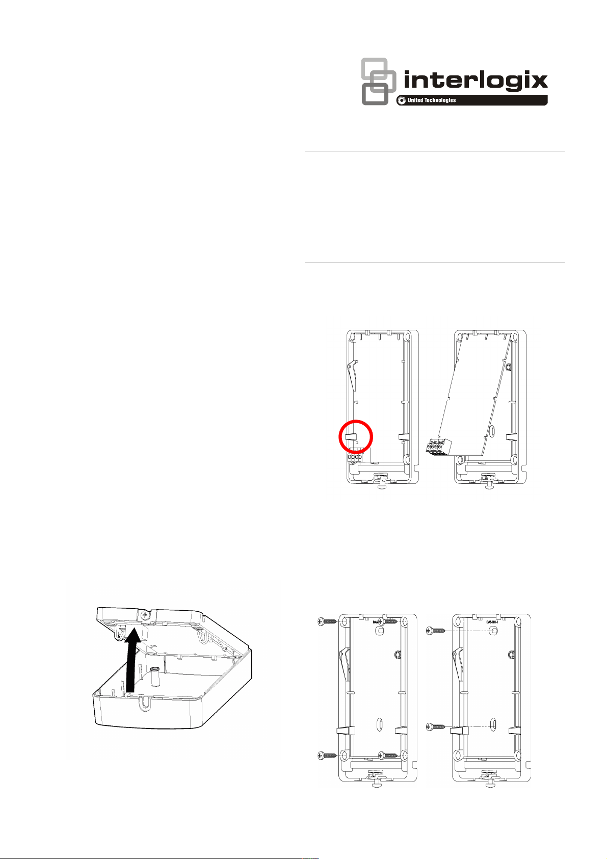
Installing the Module
1. Turn the receiver face down, loosen the
bottom screw, and lift the base upwards.
This will ensure the internal tamper switch
remains in place.
2. Carefully remove the circuit board from
the plastic housing by squeezing on the
side tabs.
3. Feed the buss cable through one of the
cable holes.
4. Screw the rear plastic housing to a fixed
surface. Higher positions generally provide
better signal reception.
PLEASE READ THE ULTRASYNC MODULAR HUB REFERENCE GUIDE BEFORE USING THIS
PRODUCT WHICH INCLUDES IMPORTANT SAFETY AND LEGAL INFORMATION
INCLUDING WARNINGS, WARRANTY DISCLAIMER S, AND LIMITATIONS OF LIABILITY,
AND COMPLETE INSTRUCTIONS ON HOW TO ENROLL AND CONFIGURE EXPANSION
MODULES. THE REFERENCE GUIDE IS AVAILABLE AT:
http://www.interlogix.com/intrusion/product/ultrasync-modular-hub
S'IL VOUS PLAÎT LIRE LE GUIDE DE REFERENCE POUR LE HUB UltraSync MODULAIRE
AVANT D'UTILISER CE PRODUIT QUI COMPREND LA SÉCURITÉ IMPORTANT ET
JURIDIQUES INFORMATIONS, Y COMPR IS LES AVERTISSEMENTS, GARANTIE
EXCLUSIONS, E T LIMITATIONS DE RESPONSABILITÉ ET INSTRUCTIONS COMP LETES SUR
COMMENT ENROLLER ET CONFIGURER LES MODULES D’EXPANSION. LE GUIDE DE
RÉFÉRENCE
EST DISPONIBL E AU: http://www.interlogix.com/intrusion/product/ultrasync-modula r-hub

UM-ZW Installer Manual RevC.docx Page 2
5. Re-install the circuit board in to the plastic
housing.
6. Connect the buss cable to J4 terminal
header on the UM-ZW. Refer to control
panel installation manual for cable
requirements.
7. Install J3 TERM link if required. Refer to
xGen Installation & Programming Guide.
8. Turn on the power to the control panel and
wait for panel to complete initialisation.
9. The LED next to the ENROLL switch will
blink three times each second to indicate it
is not learnt in. Push and hold the
ENROLL switch on the xGen panel for 3
seconds to perform enrollment.
10. The LED next to the ENROLL switch will
blink once per second to indicate it is
learnt in.
UM-ZW Device Programming
Programming is performed via the xGen
control panel.
1. Log in to the xGen control panel.
2. Click Advanced – Devices – System
Devices – Relay Expanders.
3. Select the UM-ZW device number from
the drop down box:
4. Click Expander Name to set the module
name. The default is “Z-Wave Expander”.
5. Click Save to save changes.
6. Click Back.
7. Click Expander Options.
8. If tamper is required, tick Tamper Enable.
9. Click Save to save changes.
10. Re-install the front plastic housing taking
care with the internal tamper switch, then
tighten the bottom screw.
Adding Z-Wave Devices
1. Log in to the xGen control panel.
2. Click Settings.

UM-ZW Installer Manual RevC.docx Page 3
3. Select Z-Wave Add\Remove in the drop
down menu.
4. Click Add.
5. Initiate LINK or ADD mode on Z-Wave
device. See your Z-Wave device’s manual
for instructions.
6. Note: If a Z-Wave device has been added
before or to another system, you must first
remove it before adding it to this system.
To do this, click Remove, then activate
LINK or REMOVE mode on the device.
7. Click Rooms.
8. Check you can see the device you just
added. Click a button such as ON or OFF
to verify you can control the device.
Automation Scenes
Once Z-Wave devices have been added, they
can be switched on and off in response to
system events. Refer to the xGen Installation
& Programming Guide for instructions on
creating automation scenes.
Supported Z-Wave Devices
Type
Description
Binary On/Off
Switch
Non-secure mode, for controlling appliances
such as lamps, TV, garage door opener, and
other devices that connect to a power point.
Dimmer
Non-secure mode, for controlling brightness
level of dimmable lights.
Door Locks
Secure mode only, supports locking,
unlocking, PIN code share, and status.
Thermostat
Non-secure mode, control temperature set
points, on, off, fan, mode, and temperature
reading.
Note on Range
Z-Wave devices form a wireless mesh network
where each device acts as a short-range
repeater.
Battery powered devices are not recommended
for use as repeaters due to limited battery life.
To extend the range of your Z-Wave network,
install mains powered Z-Wave devices such as
an On/Off power point.
For example, when adding a door lock, ensure
there is at least one mains powered Z-Wave
device between the lock and the UM-ZW ZWave Module to provide more reliable
wireless coverage.
Specifications
• Compatibility: xGen control panels
• Frequency: 908.42 MHz in US, 868.42
MHz in EMEA, 921.42 MHz in ANZ
• Required Power: 12.0 VDC (provided by
panel)
• Current Draw: 80 mA maximum
• Operating Temperature Range 0° to 49°C
(32° to 120°F)
• Storage Temperature: -34° to 60°C (-30° to
120°F)
• Maximum Humidity: 90% relative
humidity non-condensing
• Dimensions: 155 mm H x 95 mm W x 68
mm D
Manufacturer
Placed on the market by:
UTC Fire & Security Americas Corporation, Inc.
3211 Progress Drive, Lincolnton, NC, 28092, USA
This equipment has been tested and found to comply with the limits for a
Class B digital device, pursuant to part 15 of the FCC Rules. These limits
are designed to provide reasonable protection against harmful interference
when the equipment is operated in a commercial environment. This
equipment generates, uses, and can radiate radio frequency energy and, if
not installed and used in accordance with the instruction manual, may cause
harmful interference to radio communications.

UM-ZW Installer Manual RevC.docx Page 4
If this equipment does cause harmful interference to radio or television
reception, which can be determined by turning the equipment off and on, the
user is encouraged to try to correct the interference by one or more of the
following measures:
• Reorient or relocate the receiving antenna.
• Increase the separation between the equipment and receiver.
• Connect the equipment into an outlet on a circuit different from that
to which the receiver is connected.
• Consult the dealer or an experienced radio/TV technician for help.
This class B digital apparatus complies with Canadian ICES-3B.
Cet appareil numérique de la classe B est conforme à la norme NMB-003 du
Canada.
Caution: Any changes or modifications not expressly approved by the party
responsible for compliance to this equipment would void the user’s
authority to operate this device.
This Device complies with FCC & ISED radiation exposure limits.
This device complies with Industry Canada’s licence-exempt RSSs.
Operation is subject to the following two conditions:
(1) This device may not cause interference; and
(2) This device must accept any interference, including interference that
may cause undesired operation of the device.
Le présent appareil est conforme aux CNR d’Industrie Canada applicables
aux appareils radio exempts de licence. L’exploitation est autorisée aux
deux conditions suivantes :
1) l’appareil ne doit pas produire de brouillage;
2) l’utilisateur de l’appareil doit accepter tout brouillage radioélectrique
subi, même si le brouillage est susceptible d’en compromettre le
fonctionnement.
Fire Statement
This product may be sold in the state of California for
security and residential fire purposes only. It may not be
sold or used in conjunction with commercial fire alarm
systems per California Code of Regulations. For
installations elsewhere, consult with local authorities.
If prohibited for use with a commercial fire system, such as
in the state of California, the Manual Fire SOS button on
the keypad must be disabled in the panel (Settings –
Areas).
Copyright
© 2017 United Technologies Corporation. All rights reserved.
Contact Information
For contact information, visit us online at www.interlogix.com.
For technical support, see www.interlogix.com/support
.
Customer Support
For technical support, see www.interlogix.com/support
 Loading...