


CX2172/4
Clex private
Electronic door handle
Operating and
assembly manual

CX2172/4 TABLE OF CONTENTS
Imprint
Operating and assembly manual
Electronic door handle CX2172/4
Document number: 0704
Version: 1.41
Status: 09.07.2018
Manufacturer
Uhlmann & Zacher GmbH
Gutenbergstr. 2–4
97297 Waldbuettelbrunn
Germany
Tel.: +49 931 40672-0
E-Mail: contact@UundZ.de
http://www.UundZ.com
This operating and assembly manual is copyright protected. The information
contained this manual should not be reproduced, distributed or used for
competitive purposes or shared with third parties. It is likewise forbidden to
manufacture any component using this manual without prior written consent.
2

CX2172/4 TABLE OF CONTENTS
Table of contents
1 About this document ........................................................................ 5
1.1 Warnings ............................................................................................ 5
1.2 Symbols .............................................................................................. 5
2 Security .......................................................................................... 6
2.1 Proper use .......................................................................................... 6
2.2 Improper use ....................................................................................... 6
2.3 General safety instructions .................................................................... 6
3 Product description .......................................................................... 7
3.1 Functional description .......................................................................... 7
3.2 Design ................................................................................................ 9
3.3 Versions ............................................................................................ 12
3.4 Technical data .................................................................................. 13
3.5 Standards ......................................................................................... 17
3.6 Management accessories ................................................................... 18
4 Assembly .......................................................................................19
4.1 Assembly instructions ......................................................................... 19
4.2 Assembly .......................................................................................... 20
5 Commissioning ..............................................................................32
5.1 Programming the service key .............................................................. 32
5.2 Management as programming / clearing system .................................. 32
5.3 Management with Keyng CX2530 ....................................................... 33
5.4 Changing the settings ........................................................................ 33
6 Operation .....................................................................................34
6.1 Automatic wake up ............................................................................ 34
6.2 Opening the door.............................................................................. 34
6.3 Toggling the door handle ................................................................... 35
6.4 Signals ............................................................................................. 36
7 Cleaning and maintenance ..............................................................37
7.1 Cleaning........................................................................................... 37
7.2 Maintenance ..................................................................................... 37
8 Faults during operation ...................................................................40
8.1 Fault indications ................................................................................ 40
9 Disassembly and Disposal ................................................................41
9.1 Disassembly ...................................................................................... 41
9.2 Disposal ........................................................................................... 43
10 FAQ .............................................................................................44
10.1 Door handle does not come to rest position ......................................... 44
3

CX2172/4 TABLE OF CONTENTS
10.2 Door does not open even though the motor is running ......................... 44
11 Glossary........................................................................................45
4
CX2172/4 TABLE OF CONTENTS
Signal word
Meaning
CAUTION
Indicates a hazard with a low risk that can lead to mild or
moderate injury if not avoided.
ATTENTION
Indicates a hazard that results in property damage.
1 About this document
This operating and assembly manual describes the Clex private electronic door
handle in rosette fitting (in short: CX6172) and the electronic door fitting (in short:
CX2174). It is part of the product and contains important information that is
necessary for proper operation and maintenance.
This operating and assembly manual is valid for all versions of CX2172 and
CX2174 and is intended for technicians, who are responsible for assembling and
disassembling, as well as for end customers.
Read this operating and assembly manual carefully for smooth and safe
operation and follow the instructions given in it before operating the door
handle.
Keep the operating and assembly manual in a safe place.
After the installation, hand over the manual to the end customer and make
sure that the customer familiar with its use.
Uhlmann & Zacher GmbH does not assume any responsibility for disruptions or
hazards such as as non-access to injured personnel, malfunctions, property
damage or other damages resulting from non-compliance with this operating and
assembly manual or incorrectly configured door handles.
If there are still any doubts after reading this operating and assembly manual,
please contact your respective dealer or Uhlmann & Zacher GmbH directly.
1.1 Warnings
Warnings warn against hazards which may arise when using the door handle.
There are two levels of warnings that can be identified based on the signal word:
1.2 Symbols
The following symbols may be used in this manual:
This symbols indicates a usage instruction that must be followed by the user.
This symbol indicates an entry in a list.
This symbol indicates useful and important information.
5

CX2172/4 TABLE OF CONTENTS
2 Security
2.1 Proper use
The electronic door handle CX2172/4 is intended to be installed in building
doors and for opening the doors. It is compatible with the commonly used
European standards for locking systems.
The different versions allow it to be used in all the common doors such as wood,
steel and aluminum doors as well as doors with narrow frames having a backset
of more than 18 mm (depending on the product version).
The CX2172/4 can be used indoors as well as outdoors (depending on the
product version).
The version for fire and smoke-resistant doors, emergency exit locks can be used
on the corresponding doors. The applicable regulations should be followed.
2.2 Improper use
The CX2172/4 should not be used for locking up supplies required in case of
emergencies (for example defibrillator, emergency medication, fire extinguishers,
etc.).
The CX2172/4 should not be used in potentially explosive surroundings.
Specially approved versions that are intended for the purpose should be installed
and used in fire, smoke resistant doors and emergency exit locks. The applicable
regulations should be followed.
The CX2172/4 should not be used if the housing or the electronics is damaged.
Changes or retrofits to the product are not allowed. The knob module should not
be used outside the given specifications.
The CX2172/4 should not be used in doors that do not open freely or in doors or
lock cases that are damaged. The product should not be used as a stopper
against obstacles.
2.3 General safety instructions
Follow these basic safety instructions when using the door handle:
Installation and battery replacement should only be done by qualified
technicians according to the instructions in this operating and assembly
manual.
Do not use the door handles in potentially explosive areas.
Do not make any kind of modifications to the door handles, with the
exception of those described in this operating and assembly manual.
Do not apply paints or acids to the door handles.
Do not heat the door handle and battery beyond the specified storage
temperature.
Use only original spare parts and accessories from Uhlmann & Zacher to
prevent malfunctions and damages.
Only use batteries procured from Uhlmann & Zacher.
6

CX2172/4 TABLE OF CONTENTS
Phase 1
Phase 2
3 Product description
3.1 Functional description
The electronic door handle CX2172/4 is a product in the Clex private system.
The reading unit, the communication electronics, the mechanical system and
power supply, are integrated within the door handle.
Different transponder carriers can be used as key in the CX2172/4, for example,
ISO card or key fob.
CX2172/4 has the following system properties:
Up to 1,000 key/locking authorizations can be stored
Up to 128 events can be recorded in the fitting
Up to 32 holidays can be configured
*
Automatic summer and winter time changeover
15 weekly schedules can be programmed
Permanent engagement possible without additional power consumption
Engagement time can be programmed from 1 to 15 seconds
Can be connected to the IDS module CX6934
Pre-configured by default for 868 MHz wireless networking
Inner fitting fixed mechanically (only for one-sided electronic authorization)
Different handle shapes available
Suitable for all doors having a thickness of 30 mm to 110 mm
Square thickness of 7 mm, 8 mm, 8.5 mm, 9 mm and 10 mm are available
No cabling required
Can be combined with other systems (for example Clex prime)
Version for MIFARE
®
transponder available
Optional management via the CX2530 Keyng software
*
*
*
3.1.1 Battery management
The electronic door handle CX2172/4 comes with a battery management system,
which indicates the need for battery replacement by means of a visible and audio
signal, when the battery power reduces (capacity loss) during the final 1,000
operations of the battery (see chapter 7.2.1 Battery Replacement).
The signal is given out in two phases:
The battery needs to be changed soon.
If an authorized key is held in front of the reading unit, then the engaging of the
door handle is accompanied with flashing of red light (5 times) and 5 short
audible signals.
The battery needs to be changed immediately.
If an authorized key is held in front of the reading unit, then the red LEDs flash (5
times) accompanied by 5 short audible signals. The engaging of the door handle
is delayed by 5 seconds, during which time the green LEDs flash.
The access data, the events log, the settings of the cabinet lock and the time are
stored on non-volatile memory and thus retained even when there is no power
supply, for example, when changing the battery or if the battery discharges
completely. The time is written to the non-volatile memory once every 30 minutes.
If the power supply remains off, then the clock comes to a standstill after a few
seconds and starts running from the last stored value onwards after the power
supply is restored.
*
When using CX2530 Keyng
7

CX2172/4 TABLE OF CONTENTS
3.1.2 Event log
The last 128 events of the door handle are stored in the event log.
Event logging can be enabled or disabled for each door handle individually, to
comply with specific data privacy guidelines.
The event log can be read via the CX2530 Keyng.
8

CX2172/4 TABLE OF CONTENTS
12
1 2
3
4
65
7
8
9
10
11
6
1 2
3
4
5 6
7
8
9
10
11
126
1
Mechanical door handle
7
Reading unit
2
Locking screw
8
Electronic door handle
3
Mounting screw
9
Battery compartment
4
Opener holder (with bayonet
lock)
10
Battery
5
Square pin with spiral
clamping
11
Gripping sleeve
6
Adapter sleeve (only for 7 mm
square pin)
12
Grub screw for gripping sleeve
Circular rosette
Oval rosette
3.2 Design
3.2.1 One-sided electronic authorization
9
CX2172/4 TABLE OF CONTENTS
3
4
5 6 5
4 7
8
9
10
11 12
13
14
2
1 2
1
345 6 5
7
8910
11 12
13
14
15
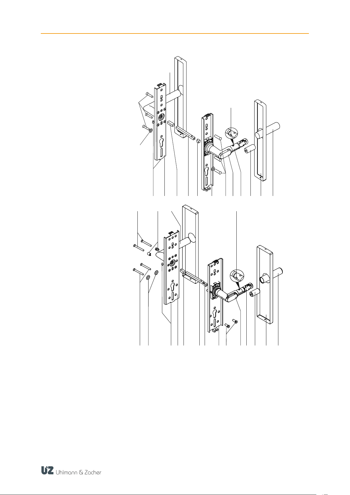
4
1
Mounting screws
9
Electronic door handle
2
Washers
10
Battery
3
Locking screws
11
Plate cover
4
Base plate
12
Gripping sleeve
5
Adapter sleeve (only for 7 mm
square pin)
13
Grub screw for gripping sleeve
6
Square pin with spiral
clamping
14
Mechanical door handle
7
Threaded sleeves
15
Screw-type sleeve
8
Reading unit
Long narrow plate
Long wide plate
10
CX2172/4 TABLE OF CONTENTS
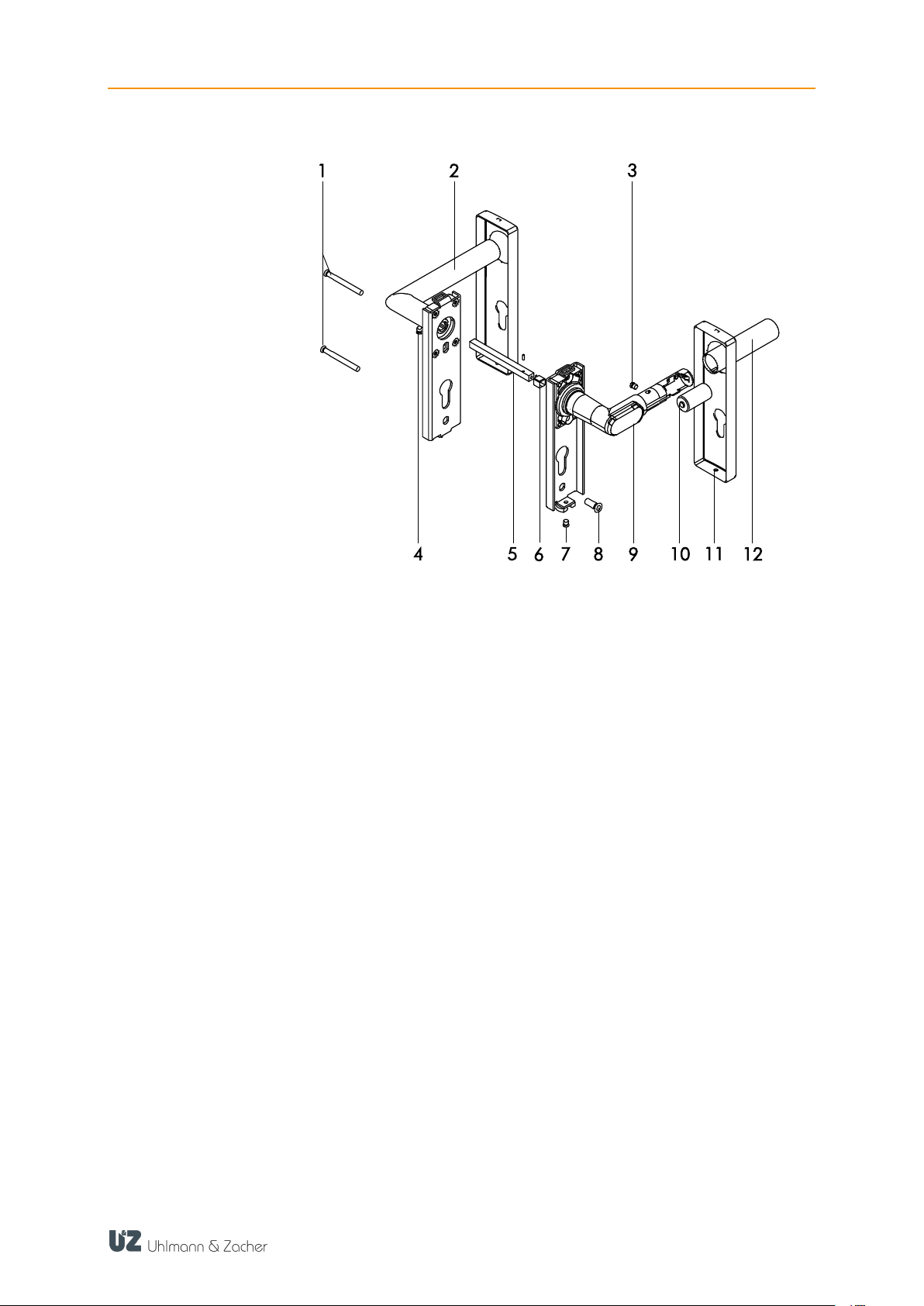
1
Mounting screws
7
Locking screw
2
Mechanical door handle
8
Threaded sleeve
3
Grub screw for gripping sleeve
9
Electronic door handle
4
Locking screw
10
Battery
5
Square pin with spiral
clamping
11
Plate cover
6
Adapter sleeve (only for 7 mm
square pin)
12
Gripping sleeve
Short plate
11

CX2172/4 TABLE OF CONTENTS
1
Reading unit
6
Rosette cover
2
Electronic door handle
(outside)
7
Electronic door handle (inside)
3
Square pin
8
Battery
4
Adapter sleeve (only for 7 mm
square pin)
9
Gripping sleeve
5
Mounting screw
10
Grub screw for gripping sleeve
3.2.2 Two-sided electronic authorization
Two-sided electronic authorization is possible only in certain combinations of the
variants circular rosette, oval rosette, long narrow plate and long wide plate.
3.3 Versions
Different opener shapes and versions are available:
Door openers in L-shape or U-shape
One or two-sided electronic authorization
Circular rosette, oval rosette, long narrow plate and long wide plate
For emergency exit locks, fire and smoke resistant doors
For door hinged on the right or left
For indoor or outdoor use
Various square sizes (7 mm, 8 mm, 8,5 mm, 9 mm, 10 mm)
12

CX2172/4 TABLE OF CONTENTS
Name
Value
Minimum backset
Circular rosette: 28 mm
Oval rosette: 18 mm
Long narrow plate: 22 mm
Long wide plate: 33 mm
Door thickness
30 mm to 110 mm
Maximum door weight
300 kg
Swivel angle
45°
Transponder
MIFARE® Classic (868 MHz)
MIFARE® DESFire® (868 MHz)
Active transponder (868 MHz)
Radio
Frequency: 868.3 MHz
Maximum transmission power: 1 mW
Power supply,
Rated voltage
CR123A 3V battery (1 piece),
3 volts
Battery life
up to 170,000 operations or 9.8 years
Power consumption in
sleep mode
0.06 mW
Name
Value
Operating
temperature
+5°C to +55°C (indoor version)
-25°C to +65°C (outdoor version)
Storage
temperature
-40°C to +65°C
Maximum relative
humidity (door
handle)
Up to 95% non-condensing
Installation location
Indoor or outdoor (depending on the product model)
Protection class
Indoor version: IP40
Outdoor version: IP66
3.4 Technical data
3.4.1 General technical data
3.4.2 Ambient conditions
13

CX2172/4 TABLE OF CONTENTS
Circular rosette
electronics side and
handle versions
Circular rosette
mechanical side and
handle versions
Oval rosette
electronics side
Oval rosette
mechanical side
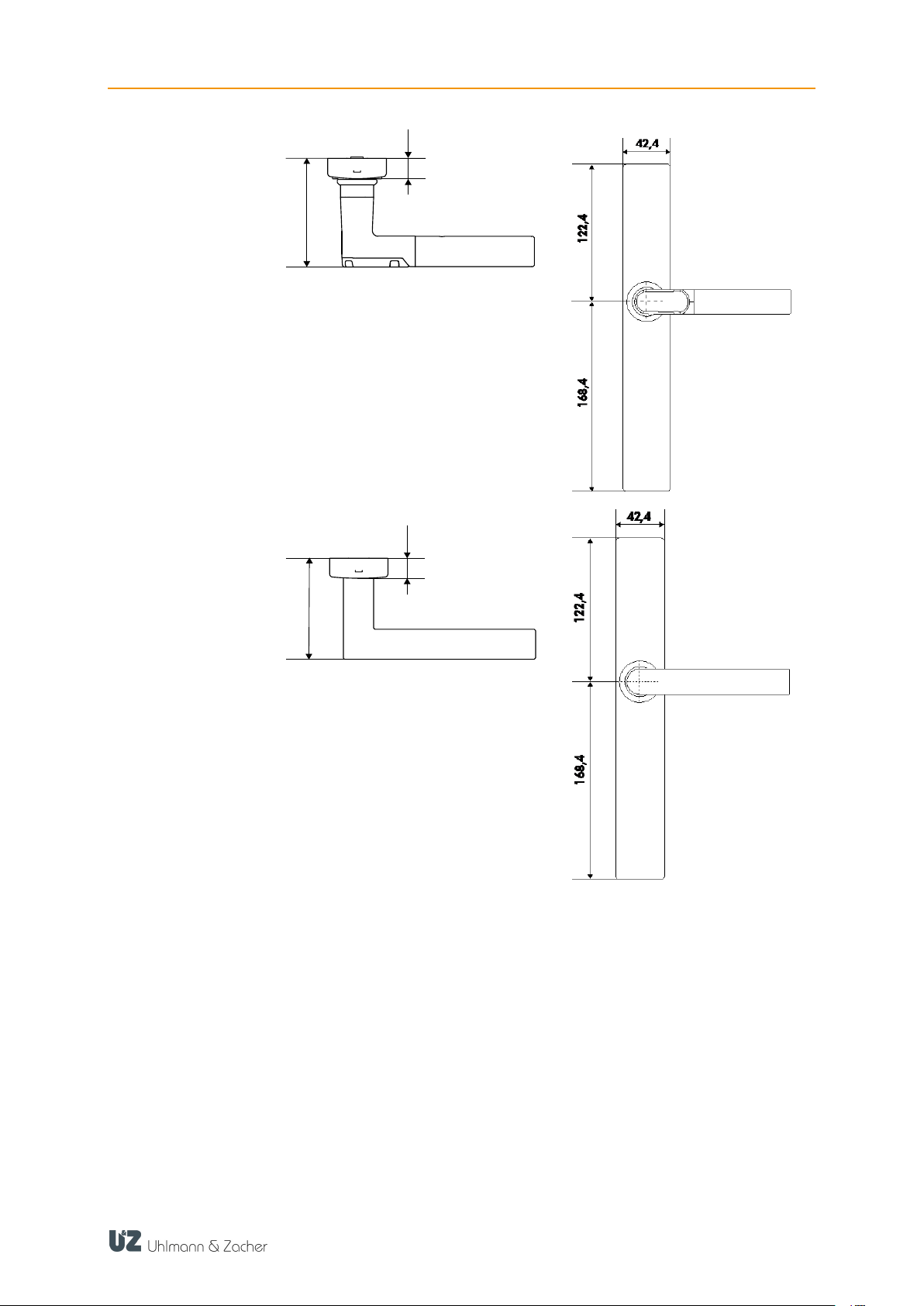
3.4.3 Dimensions
14
CX2172/4 TABLE OF CONTENTS
14,7
79,0
14,7
75,5
Long narrow plate
electronics side
Long narrow plate
mechanical side
15

CX2172/4 TABLE OF CONTENTS
14,7
79,0
75,5
14,7
Long wide plate
electronics side
Long wide plate
mechanical side
16

CX2172/4 TABLE OF CONTENTS
75,5
14,7
Short plate electronics
side
Short plate mechanical
side
14,7
79,0
3.5 Standards
The electronic door handle CX2172/4 meets the following standards:
prEN 16867:2015
EN 1906:2012
17

CX2172/4 TABLE OF CONTENTS
3.6 Management accessories
3.6.1 CX2530 Keyng
The CX2530 Keyng management software helps easy management of the
electronic locking system Clex private via the PC. The software, in comparison to
the learning / clearing system, offers an extended function range.
The communication between the locking units and the management software
takes place via a USB wireless stick.
3.6.2 Service key
Using the service key, a user identifies himself as an administrator of the locking
system. If the service key is held in front of a component of the locking system,
then the respective component goes into programming mode. It is then possible,
for example, to authorize keys, adjust settings or read the event log.
18

CX2172/4 TABLE OF CONTENTS
CAUTION
Damage to the door handle by mounting screws that are too
long
The cover of the electronic door handle can be damaged if
the mounting screws are too long!
Circular rosette
Oval rosette
Long plate
Short plate
4 Assembly
4.1 Assembly instructions
4.1.1 General assembly instructions
Check the approval when installing the CX2172/4 door handle in a fire /
smoke resistant door or in an escape door.
If a cylinder holder is present in the door, then it should be sealed properly,
for e.g. using a dummy cylinder.
Carry out the assembly with the door open.
Ensure that the latches or seals fitted to the door do not hinder the proper
operation of the CX2172/4.
Ensure that the door handle does not protrude and prevent the door from
swinging freely.
When installing the CX2172 door handle in the circular and oval rosettes
version, the hole in the door for inserting the handle pin should have a
diameter of at least 25 mm.
When installing the CX2174 door handle in the long plate version, the plate
has to be fixed at least at four points distributed as evenly as possible over the
length, such that the corresponding force can be applied on the plate.
Before assembling the door handle, always check whether all the components
can move freely.
After assembly, check the function with the door open.
4.1.2 Drilling template
The drilling template supplied is used to mark the drilling holes.
There should be a distance of at least 38 mm between the two drilling holes for
the handle rosette and that for the key rosette.
There should be a distance of at least 50 mm between the two drilling holes for
the handle rosette and that for the key rosette.
The base plates of the two long plate versions are provided with holes for
different doors. Usually the same holes are used for the long narrow plate version
as for the oval rosettes versions, for the wide version that of the circular rosette
version.
The base plate of the short plate is provided with holes for mounting a short
plate. Usually the upper short plate hole and a hole below the locking cylinder
are used for fixing.
19

CX2172/4 TABLE OF CONTENTS
1
Electronic door handle
2
Spiral clamping pin
3
Square
4
Adapter sleeve for square (only for 7 mm square)
1
3 2 4
4.2 Assembly
4.2.1 Assembling the square pin
The square pin has to be assembled before installation on the electronic
door handle (outside). This applies to all the versions and is shown here
using an example of the circular rosette version.
Insert the adapter sleeve into the square holder (if required)
Insert the square onto the retaining pin and into the square holder
Insert the spiral clamping pin into the square
20

CX2172/4 TABLE OF CONTENTS
Circular rosette
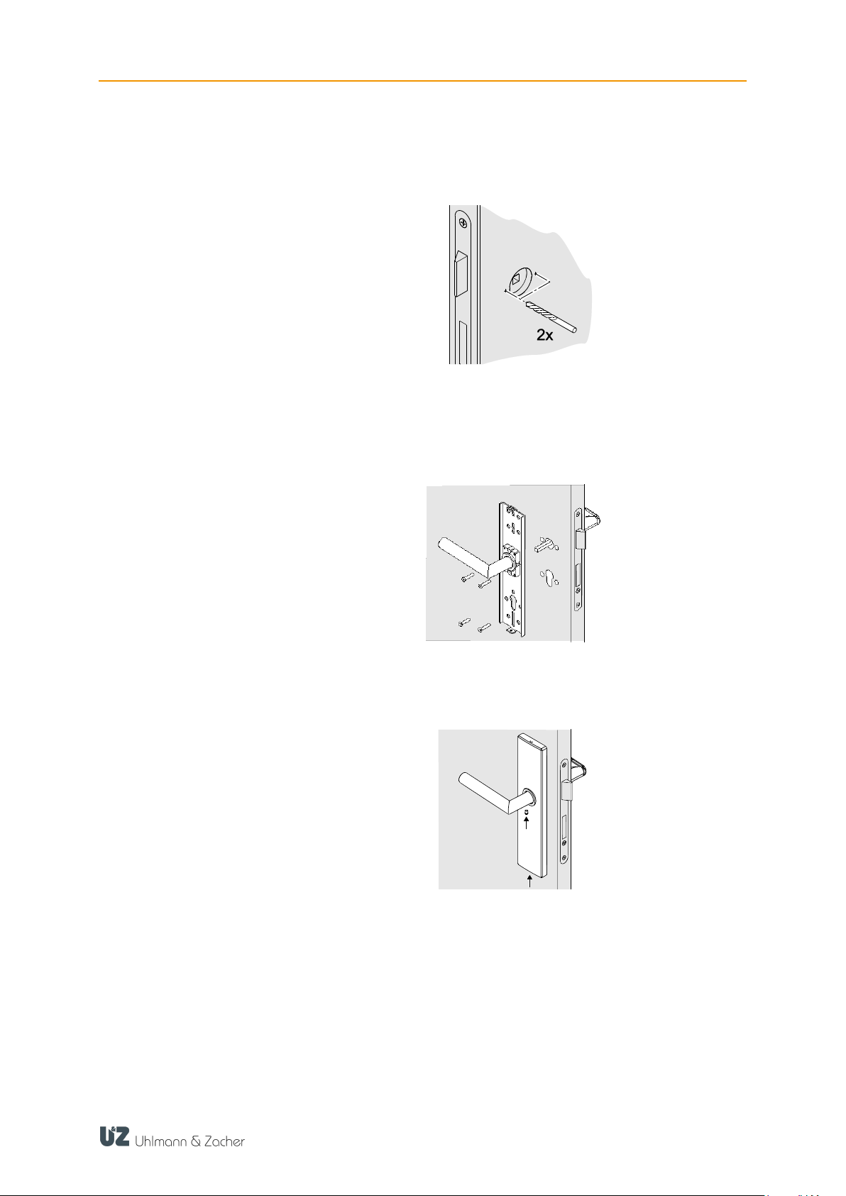
4.2.2 One-sided electronic authorization
Insert the square pin of the electronic door handle into the square nut of the
lock.
Place the drilling template on the square pin, align horizontally and centre
punch the hole markings.
Remove the square pin again.
Drill holes of diameter 8 - 8.5 mm at the marked positions. Do not drill into
or through the lock casing.
Insert the square pin of the electronic door handle once again into the
square nut of the lock. If necessary place the adapter sleeve supplied on the
square pin.
21

CX2172/4 TABLE OF CONTENTS
Insert the holder of the mechanical door handle from the other side and
screw it along with the electronic door handle through the door panel. Use
the supplied mounting screws.
Insert the mechanical door handle keeping it in a horizontal position. For
door handles pointing to the right, tighten the rosette towards the left, guide it
over the handle holder and engage the bayonet lock. Accordingly, tighten
the rosette towards the right for door handles pointing to the left.
Insert the locking screw from the bottom of the handle and tighten it.
Check the functionality and easy movement of the door handle with the door
open. The handle is already engaged when delivered.
When engaged, the catch of the lock should be completely inside the lock
casing when the latch is pressed down.
To operate the door handle, insert the battery and close the housing (see
chapter 7.2.17.2.1 Battery replacement). The electronic door handle
disengages only after the battery is inserted.
After holding up an authorized key for the first time, only the two upper LEDs
light up as an indication.
22

CX2172/4 TABLE OF CONTENTS
Oval rosette
The oval rosette version is mostly used for tubular frame doors. These doors
often have pressed threaded bushes, such that the base plate has to just be
screwed onto the door. Other types of attachment depend on the various
door designs and are not explained here.
Pull the rosette cover of the electronic door handle back, turn by 90° and
screw the electronic door handle onto the door panel. Insert the holder of the
mechanical door handle from the other side and screw it to the door panel as
well. Use the supplied mounting screws.
Replace the rosette cover of the electronic door handle on the rosette.
Insert the mechanical door handle keeping it in a horizontal position. For
door handles pointing to the right, tighten the rosette towards the left, guide it
over the handle holder and engage the bayonet lock. Accordingly, tighten the
rosette towards the right for door handles pointing to the left.
Insert the locking screw from the bottom of the handle and tighten it.
Check the functionality and easy movement of the door handle with the door
open. The handle is already engaged when delivered.
When engaged, the catch of the lock should be completely inside the lock
casing when the latch is pressed down.
23

CX2172/4 TABLE OF CONTENTS
Long narrow plate
To operate the door handle, insert the battery and close the housing (see
chapter 7.2.17.2.1 Battery replacement). The electronic door handle
disengages only after the battery is inserted.
After holding up an authorized key for the first time, only the two upper LEDs
light up as an indication.
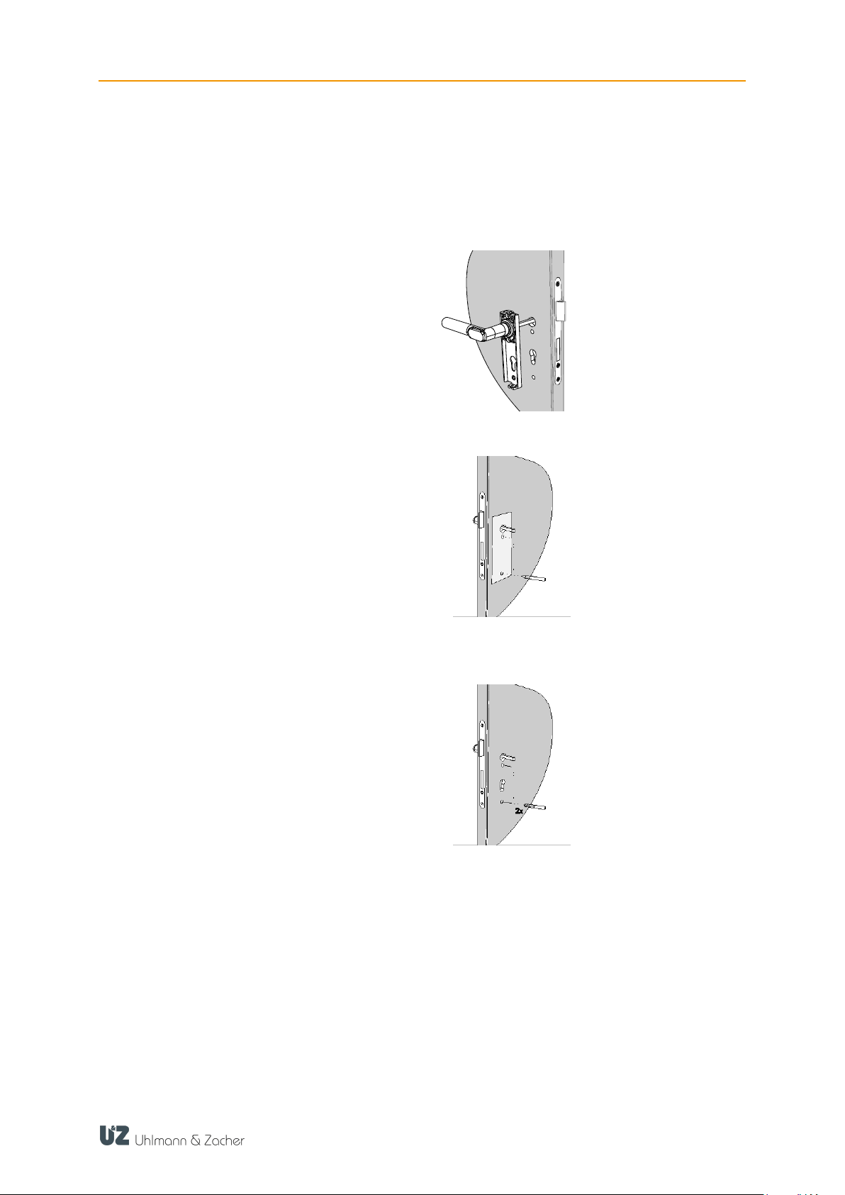
The long plate narrow version is mostly used for tubular frame doors. These
doors often have pressed threaded bushes, such that the base plate has to
just be screwed onto the door. Other types of attachment depend on the
various door designs and are not explained here.
Insert the square pin of the electronic door fitting into the square nut of the
lock.
Screw the base plate of the electronic fitting onto the door panel. Use the
supplied mounting screws.
Insert the base plate of the mechanical door handle from the other side and
screw it to the door panel. Use the supplied mounting screws.
24

CX2172/4 TABLE OF CONTENTS
Long wide plate
Place the plate cover of both the door handles on the base plate and
unscrew the locking screw at the bottom of the plate such that the plate sits
firmly.
Insert the locking screw from the bottom of the handle and tighten it.
Check the functionality and easy movement of the door handle with the door
open. The handle is already engaged when delivered.
When engaged, the catch of the lock should be completely inside the lock
casing when the latch is pressed down.
To operate the door handle, insert the battery and close the housing (see
chapter 7.2.17.2.1 Battery replacement). The electronic door handle
disengages only after the battery is inserted.
After holding up an authorized key for the first time, only the two upper LEDs
light up as an indication.
The long wide plate is mostly used in doors, where the holes are available for
a circular rosette in the lock casing. These holes are used to fix the base plate.
The holes have to be drilled in the door subsequently if required, as described
below. Other types of attachment depend on the various door designs and
are not explained here.
Insert the square pin of the electronic door handle into the square nut of the
lock.
Place the drilling template on the square pin, align horizontally and centre
punch the hole markings.
25
CX2172/4 TABLE OF CONTENTS
Remove the square pin again.
Drill holes of diameter 8 - 8.5 mm at the marked positions. Do not drill into
or through the lock casing.
Insert the square pin of the electronic door handle once again into the square
nut of the lock. If necessary place the adapter sleeve supplied on the square
pin.
Insert the base plate of the mechanical door handle from the other side and
screw it along with the electronic door handle through the door panel. Use the
mounting screws and threaded bolts provided.
Place the plate cover of both the door handles on the base plate and unscrew
the locking screw at the bottom of the plate such that the plate sits firmly.
Insert the locking screw from the bottom of the mechanical door handle and
tighten it.
Check the functionality and easy movement of the door handle with the door
open. The handle is already engaged when delivered.
When engaged, the catch of the lock should be completely inside the lock
casing when the latch is pressed down.
To operate the door handle, insert the battery and close the housing (see
chapter 7.2.17.2.1 Battery replacement). The electronic door handle
disengages only after the battery is inserted.
After holding up an authorized key for the first time, only the two upper LEDs
light up as an indication.
26
CX2172/4 TABLE OF CONTENTS
Short plate
The short plate is mostly used in steel doors, where the two standardised holes
for a short plate fitting are often already present. The holes have to be drilled
in the door subsequently if required, as described below.
Insert the square pin of the electronic door handle into the square nut of the
lock.
Place the drilling template on the square pin, align horizontally and centre
punch the hole markings.
Remove the square pin again.
Drill holes of diameter 8 - 8.5 mm at the marked positions. Do not drill into
or through the lock casing.
Insert the square pin of the electronic door handle once again into the square
nut of the lock. If necessary, place the adapter sleeve supplied on the square
pin.
27

CX2172/4 TABLE OF CONTENTS
Insert the base plate of the mechanical door handle from the other side and
screw it along with the electronic door handle through the door panel. Use the
mounting screws and threaded bolts provided.
Place the plate cover of both the door handles on the base plate and unscrew
the locking screws at the bottom of the plate such that the plate covers sit
firmly.
Insert the locking screw from the bottom of the mechanical door handle and
tighten it.
Check the functionality and easy movement of the door handle with the door
open. The handle is already engaged when delivered.
When engaged, the catch of the lock should be completely inside the lock
casing when the latch is pressed down.
To operate the door handle, insert the battery and close the housing (see
chapter 7.2.1 Battery replacement). The electronic door handle disengages
only after the battery is inserted.
After holding up an authorized key for the first time, only the two upper LEDs
light up as an indication.
28
CX2172/4 TABLE OF CONTENTS
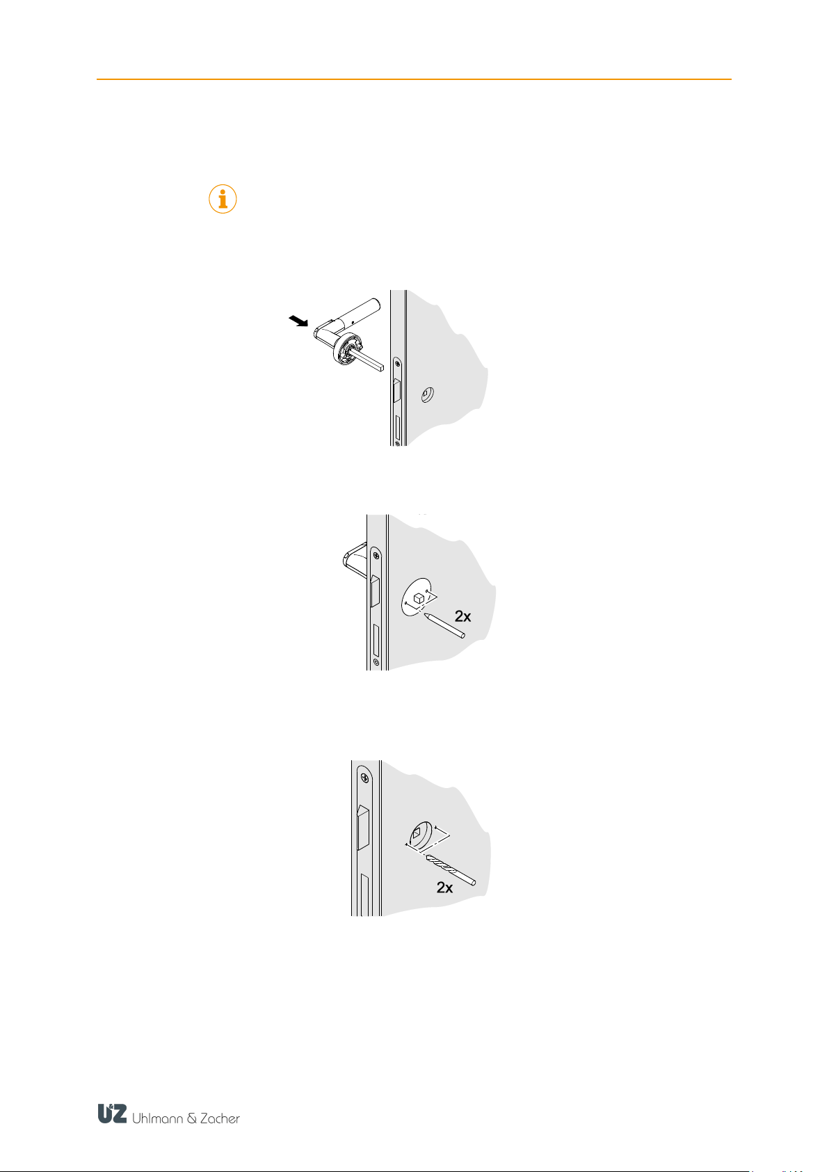
4.2.3 Two-sided electronic authorization
Two-sided electronic authorization is possible in the versions of circular rosette,
oval rosette, long narrow plate and long wide plate.
Insert the square pin of the outer electronic door handle into the square nut
of the lock.
Place the drilling template on the square pin, align horizontally and centre
punch the hole markings.
Remove the square pin again.
Drill holes of diameter 8 - 8.5 mm at the marked positions. Do not drill into
or through the lock casing.
Insert the square pin of the outer electronic door handle once again into the
square nut of the lock. If necessary place the adapter sleeve supplied on the
square pin.
Check the extent to which the square pin protrudes out of the door panel and
shorten it if required, in order to completely insert the inner electronic door
handle. The square pin should protrude 6 mm ± 0.5 mm over the door
panel, to ensure proper functioning.
29

CX2172/4 TABLE OF CONTENTS
Retract the rosette cover of the inner electronic door handle to the maximum
extent and screw both the electronic door handles together through the door
panel. Use the supplied mounting screws.
Place the rosette cover.
To operate the door handle, insert the battery and close the housing (see
chapter 7.2.17.2.1 Battery replacement).
Check the functionality and easy movement of the door handle with the door
open. To do this, hold an authorized key in front of the reading unit.
When engaged, the catch of the lock should be completely inside the lock
casing when the latch is pressed down.
After holding up an authorized key for the first time, only the two upper LEDs
light up as an indication.
30
CX2172/4 TABLE OF CONTENTS
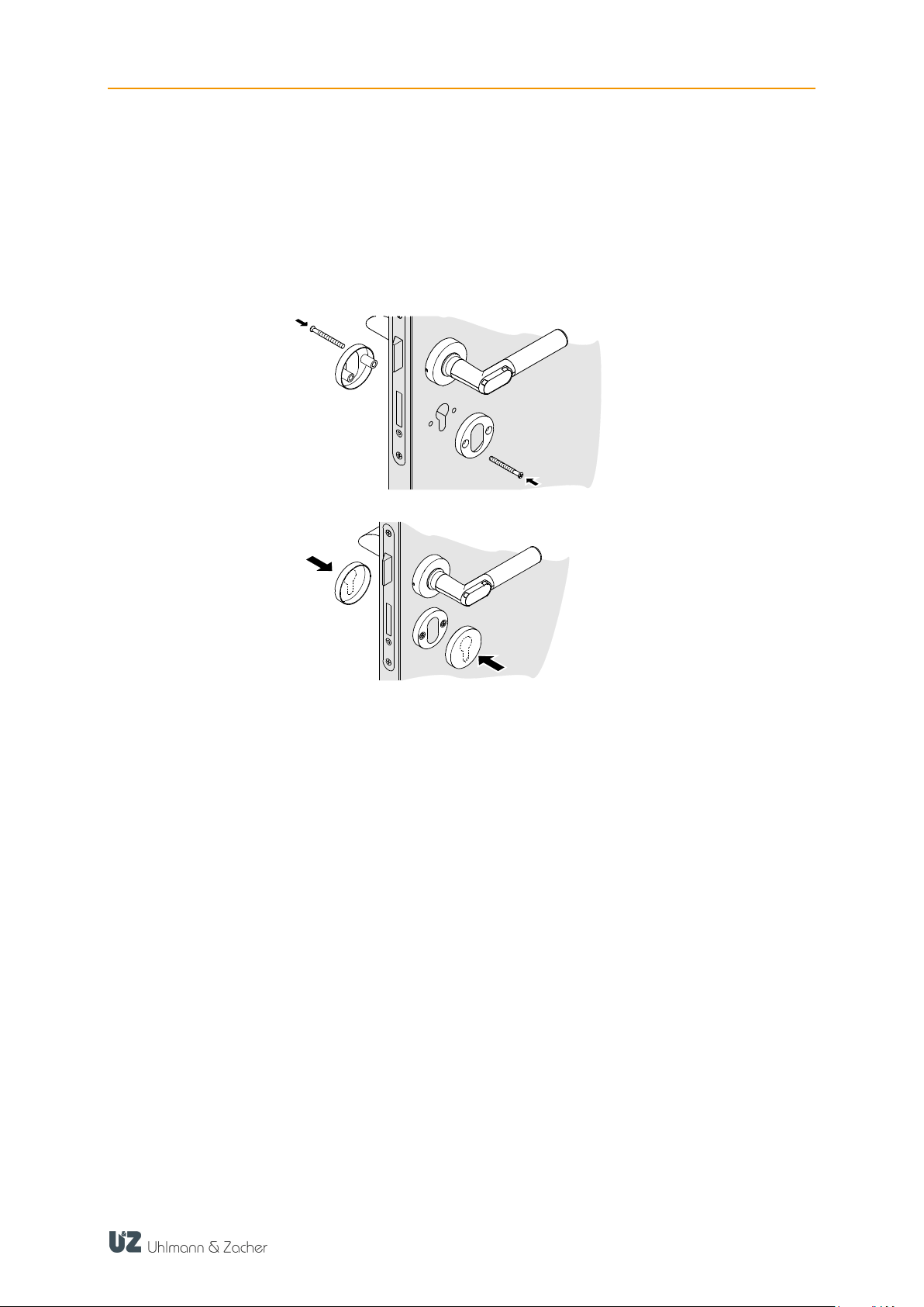
4.2.4 Assembling the key rosette
Place the drilling template, align horizontally and center punch the hole
marks.
Drill holes of diameter 7 - 7.5 mm at the marked positions. Do not drill into
or through the lock casing.
Screw both the key rosettes together through the door panel.
Place the rosette covers and press firmly, till they engage audibly.
31

CX2172/4 TABLE OF CONTENTS
5 Commissioning
Basically, there are two ways of managing a Clex private locking system and
thereby programming the electronic door handles:
Management as programming / clearing system
Management using the CX2530 Keyng software and wireless stick
5.1 Programming the service key
In its original condition (delivery status), the service key is not yet programmed
into the electronic door handle. For example, to program the service key, the
door handle is woken up by holding a key in front of the reading unit. Upon
success, the door handle responds with three long audible beeps. Within the next
15 seconds, the service key can be programmed by holding it in front of the
reading unit. Once the service key has been programmed successfully, the door
handle indicates this with two short and one long beep.
After programming, the door handle enters the programming mode when the
service key is held up.
5.2 Management as programming / clearing system
5.2.1 Programming the key
Hold the service key in front of the reading unit of the door handle. The door
handle enters the programming mode.
Hold the key to be programmed in front of the reading unit until two short
audible signals indicate the success.
Optionally, program additional keys as described in the previous step.
Hold the service key in front of the reading unit or wait 15 seconds to exit the
programming mode.
To create a key with toggle authorisation, hold the key for 3 seconds in front of
the reading unit during the programming process until the success is indicated by
3 short audible signals.
5.2.2 Delete key
Hold the service key in front of the reading unit of the door handle. The door
handle enters the programming mode.
Hold the key to be deleted in front of the reading unit until two long audible
signals indicate success.
Optionally, delete additional keys as described in the previous step.
Hold the service key in front of the reading unit or wait 15 seconds to exit the
programming mode.
5.2.3 Delete all keys
Hold the service key in front of the reading unit of the door handle. The door
handle enters the programming mode.
Hold up the service key until the door handle exits the programming mode.
Within 60 seconds, return the door handle to the programming mode and
hold up the service key in front of the reading unit. In the meantime, the door
handle indicates success using short audible beeps.
32

CX2172/4 TABLE OF CONTENTS
Once the programming mode is exited after 15 seconds, all the keys would
have been deleted.
5.3 Management with Keyng CX2530
The CX2530 Keyng software enables convenient and easy management of the
electronic locking system.
You will find more detailed information in the CX2530 Keyng documentation.
5.4 Changing the settings
The following settings can be adjusted using the CX2530 Keyng software:
Time
Enable/disable the event log
Locking time (defines how long the door handle remains connected after
holding up an authorised key).
Wake-up sensitivity
Radio response of the door handle (wake-on-radio mode)
33

CX2172/4 TABLE OF CONTENTS
6 Operation
The electronic door handle operates only the latch. Hence it should be ensured
that the locking cylinder of the door is unlocked or the door is not locked in some
other manner. Otherwise, the door cannot be opened even after holding up an
authorized key.
6.1 Automatic wake up
The door handle is in sleep mode as long as it is not used. To check the
authorization of a key, it needs to be woken up from the sleep mode. This
normally happens automatically when a key is held in front of the reader unit.
If, however, the electronic door handle has been woken up 24 times (for example
by metallic objects in the surroundings) without reading a key, then automatic
wake up is disabled.
In this case the door handle has to be woken up manually.
Press the door handle a few times to wake up the reading unit, till an LED
starts glowing.
Hold up the key in front of the reading unit only after this.
The automatic activation is reactivated when an authorized key is scanned.
The wake up sensitivity (that is the number of times the door handle need to be
pressed to wake up the reading unit) can also be configured.
6.2 Opening the door
Precondition: Handle is in horizontal position.
Hold the authorised key in front of the reading unit till the green LED starts
glowing.
The door handle engages and the door can be opened by pressing the door
handle.
The time duration for which the door handle remains engaged can be configured
(1 to 15 seconds, the default value is 5 seconds). After successful authorization
(engaging) at the door handle, the engagement time starts counting down. The
engagement-time timer is reset as soon as the door handle is pressed.
The door handle disengages after the configured engagement time, if it is not
pressed or when it is pressed and held.
The door handle disengages immediately, if it is released.
34

CX2172/4 TABLE OF CONTENTS
6.3 Toggling the door handle
Hold the key with toggle authorisation for two locking cycles in front of the
reading unit.
Depending on the initial state, the door handle either engages or disengages
permanently.
35

CX2172/4 TABLE OF CONTENTS
Function
Signal (audible and visible) and explanation
Rest mode
No audible or visible signal
Programming
mode start
Long beep followed by a short beep
Programming
mode end
Short beep followed by a long beep
Key programmed
2 short beeps, LEDs glow green
Key cleared
2 long beeps, LEDs glow red
Read mode (after
waking)
Red LEDs start flashing
Key not authorised
Long low beep, red LEDs start glowing
Key authorised
Green LEDs start glowing
Toggling On
Long loud beep, green LEDs start glowing
Toggling Off
Long loud beep, red LEDs start glowing
Reset
Long low beep, all the LEDs are switched on briefly one after
the other
Battery warning
Phase 1:
5 short loud beeps, red LEDs flash 5 times simultaneously
Battery warning
Phase 2:
5 short loud beeps, red LEDs flash 5 times simultaneously,
then 5 seconds engagement delay, green LEDs start flashing
at the same time
Battery warning
Phase 3:
5 short loud beeps, red LEDs flash 5 times simultaneously, no
connection but change battery position
Hold up authorized
key with door
handle pressed
No engagement, 3 brief high audible signals, then green LED
flashes once
▬ ●
●
▬
▬ ▬ ● ● ● ● ●
● ● ● ● ●
● ● ●
5 s
▬
▬
● ●
▬
▬
● ● ● ● ●
6.4 Signals
36

CX2172/4 TABLE OF CONTENTS
CAUTION
Danger of injury caused by improper use
Do not charge, open or heat the battery.
Always replace discharged batteries with new batteries.
Pay attention to the correct polarity when inserting the
batteries.
7 Cleaning and maintenance
7.1 Cleaning
Clean the door handle with a slightly damp cloth. Use only commercially
available household cleaners.
Do not use any abrasive or caustic cleaning agents.
7.2 Maintenance
7.2.1 Replacing the battery
Change the battery only with the door open. As long as the battery is removed,
the door handle cannot engage and thus cannot open the door.
Using the Allen key provided, countersink the screw on the inside of the door
handle.
Remove the gripping sleeve.
Remove the used battery and insert the new battery, paying attention to the
polarity. The minus pole of the battery faces towards the gripping sleeve.
If the door handle is used outdoors, then replace the sealing ring of the door
handle (see chapter 7.2.2 Replace the sealing rings, page 38).
Insert the gripping sleeve back.
37

CX2172/4 TABLE OF CONTENTS
CAUTION
Damage to the sealing ring caused by improper handling
Do not use any sharp objects and do not stretch the sealing
ring more than what is required for mounting.
Unscrew the screw on the inside of the door handle till the stop, such that the
gripping sleeve cannot be removed.
When managing the locking system using the Keyng software, check the door
handle time, using Keyng CX2530 and adjust it if required.
7.2.2 Replace the sealing rings (for the outdoor version of the doors)
The outdoor version of the electronic door handle is provided with two seals
(large sealing ring and grub screw with sealing ring) which prevent water from
entering. To further ensure the leak-tightness of the electronic door handle, both
the seals have to be replaced every time the handle is opened. These are
available as a set from your dealer.
Precondition: Gripping sleeve is removed (see chapter 7.2.1Replacing the
battery, Page 37)
7.2.2.1 Replace the large sealing ring
Precondition: Gripping sleeve is removed (see chapter 7.2.1Replacing the battery
, Page 37)
To remove the sealing ring, hold down the sealing ring on one side with the
thumb and slide the finger nail of the middle finger on the opposite side. The
sealing ring can now be grasped by the index finger.
Insert a new sealing ring.
7.2.2.2 Replace the sealing ring with grub screw
Unscrew the screw on the inside of the door handle in the direction of "1"
completely and replace it with the new grub screw from the set. Insert the
screw again until it stops in the direction of "2".
38

CX2172/4 TABLE OF CONTENTS
39

CX2172/4 TABLE OF CONTENTS
Function
Audible signal
Explanation
Memory fault /
configuration fault
▬ ▬ ▬ ▬ ▬ ●
5 long beeps,
1 short beep
Coupling error
▬ ▬ ▬ ▬ ▬ ● ●
5 long beeps,
2 short beeps
RTC fault (clock)
▬ ▬ ▬ ▬ ▬ ● ● ●
5 long beeps,
3 short beeps
Internal error
(unhandled interrupt)
▬ ▬ ▬ ▬ ▬ ● ● ● ●
5 long beeps,
4 short beeps
Internal error
(bus conflict)
▬ ▬ ▬ ▬ ▬ ● ● ● ● ●
5 long beeps,
5 short beeps
Internal error
(bus conflict)
▬ ▬ ▬ ▬ ▬ ● ● ● ● ● ●
5 long beeps,
6 short beeps
Internal error
(bus conflict)
▬ ▬ ▬ ▬ ▬ ● ● ● ● ● ● ●
5 long beeps,
7 short beeps
8 Faults during operation
8.1 Fault indications
If the faults mentioned above occur repeatedly, then please contact the
concerned dealer.
40

CX2172/4 TABLE OF CONTENTS
9 Disassembly and Disposal
9.1 Disassembly
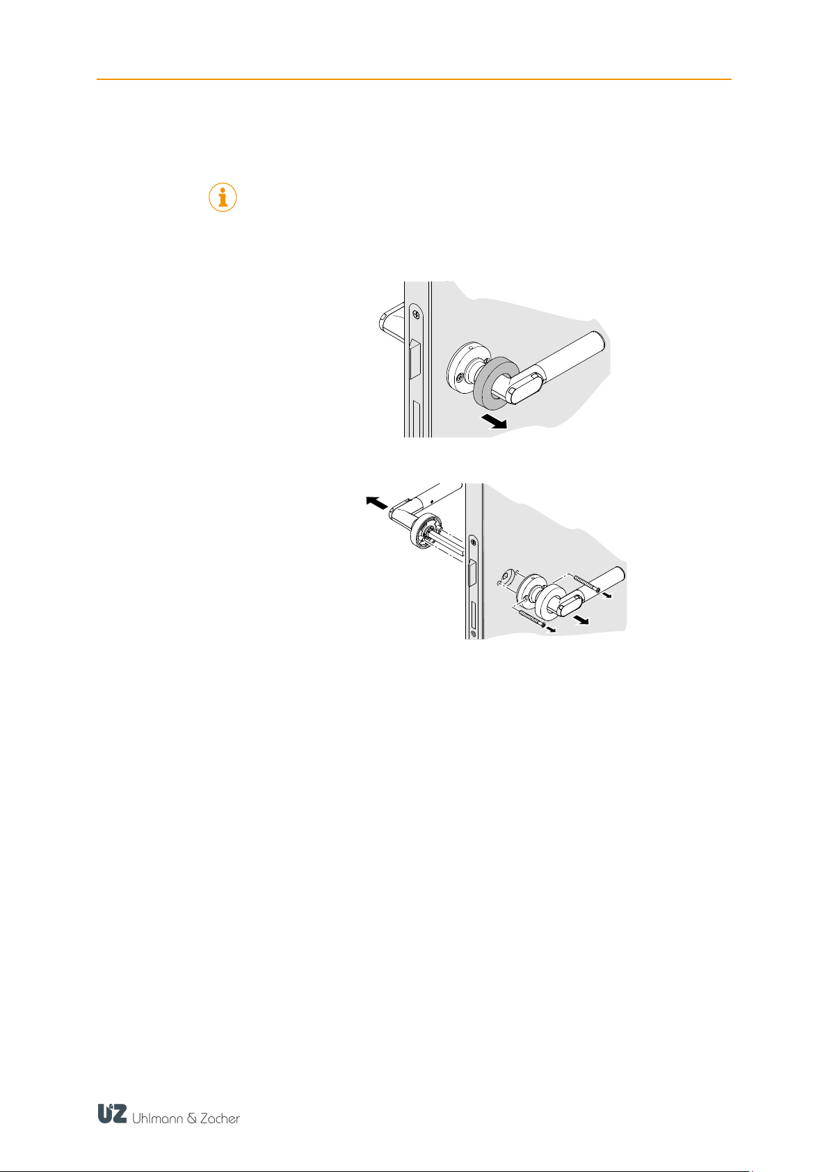
9.1.1 One-sided electronic authorization
Unscrew the locking screw at the bottom of the rosette.
Loosen the bajonet lock. To do this, tighten the rosette to the left for door
handles pointing to the right and remove the mechanical door handle from
the square pin. Accordingly, tighten the rosette towards the right for door
handles pointing to the left.
Unscrew the handle holder. Remove the electronic door handle from the
lock.
41
CX2172/4 TABLE OF CONTENTS
9.1.2 Two-sided electronic authorization
Two-sided electronic authorization is possible in the versions of circular rosette,
oval rosette, long narrow plate and long wide plate.
Lift the rosette cover on the inner electronic door handle using a small
screwdriver and pull it back as far as possible.
Loosen the mounting screws. Remove the inner electronic door handle from
the square pin. Remove the outer electronic door handle from the lock.
42
CX2172/4 TABLE OF CONTENTS
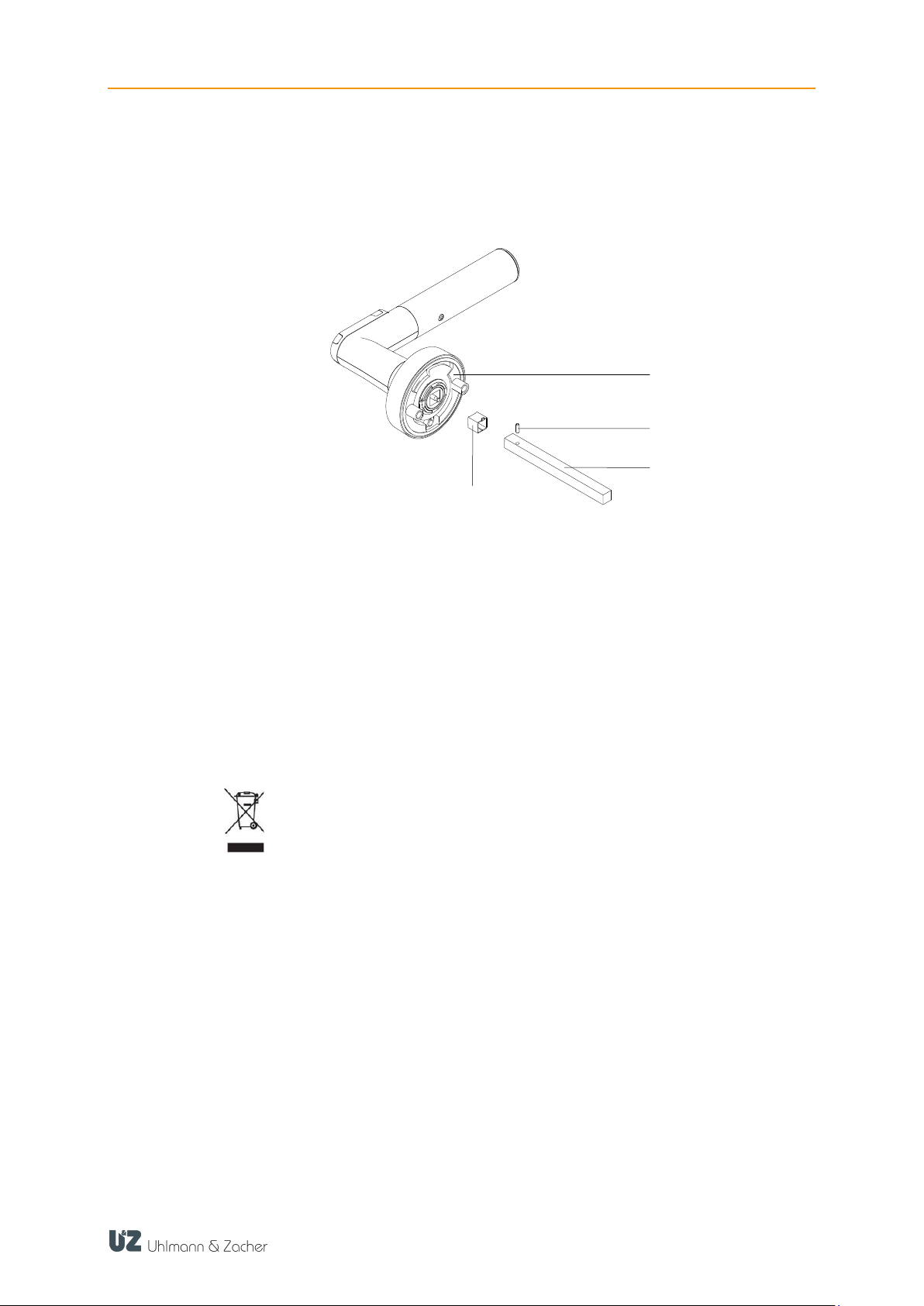
1
Electronic door handle
2
Spiral clamping pin
3
Square
4
Adapter sleeve for square (only for 7 mm square)
1
3 2 4
9.1.3 Removing the square pin
For shortening the square or if the length of the square does not match the lock,
it may be necessary to remove the square.
Remove the spiral clamping pin from the square using a punch
Remove the square from the holder.
Remove the adapter sleeve from the square holder (if required)
9.2 Disposal
Do not dispose the door handle with domestic waste. Disposal should be in
accordance with the European Directive 2002/96/EC at a collection point
for electrical waste.
Defective or used batteries should be recycled in accordance with the
European Directive 2006/66/EC.
Follow the local regulations on separate disposal of batteries.
Recycle the packaging in an eco-friendly manner.
43

CX2172/4 TABLE OF CONTENTS
10 FAQ
10.1 Door handle does not come to rest position
If the electronic door handle does not come to horizontal resting position by itself
after being assembled, it may be due to the fact that the lock is not aligned
properly. This can be partly corrected by increasing the hole diameter from 8 to
8.5 mm for mounting the door handle. The door handle can be mounted without
any stresses.
10.2 Door does not open even though the motor is running
If the motor of the electronic door handle moves audibly when an authorised
transponder is held up, but does not engage, then the position of both the door
handles with respect to the lock casing has to be checked in resting position. Both
the door handles have to be at 90° ± 1° with respect to the lock casing.
44

CX2172/4 TABLE OF CONTENTS
Definition
Description
IDS
Intrusion Detection System (IDS)
Keyng
Software for managing a locking system
MIFARE®
Technology for contactless transfer of identification data
Key
Data carrier that contains the authorization information. This
can, for example, be an ISO card or a chip. The key is
sometimes also known as transponder.
Service key
A special key with which you can identify yourself as the
administrator of the locking system.
Toggling
Permanently engaging a door handle, so that the door can
be opened without a key.
Transponder
See key
WoR
Wake-on-radio (radio response of a door handle)
11 Glossary
45
 Loading...