


1
Gantry Crane 1:87
Description
This gantry crane was built in large numbers and can still be found at many load tracks today.
This finished model is constructed very finely in detailed plastic. Quiet miniature motors with me tal
transmissions lift and lower the crane hook and move the trolley. The crane has two adjustable
outputs e.g. for lighting, lifting magnet or grip arm.
The model is equipped with a digital decoder, so that all functions can be controlled with either a DCC
or Märklin Motorola Digital Center. Using the key connections, analog operation is also possible.
Packing contents
x Gantry crane fully assembled
x Roof with two bearers for optional mounting
x Instructions
x Adhesive label
Unpacking
Remove the upper foam material and then
the lower foam material block from the
packing. Hold the gantry crane by the base
plate and carefully remove the middle
foam block from the packing. The middle
foam block consists of two sections
between which the crane hook is located.
Tip: In order to avoid damage we
recommend that you only transport the
gantry crane in this packing.
Roof assembly
If desired glue the enclosed bearers to the
intended location under the roof.
The roof should either be placed or only
loosely fixed so that the trolley remains
accessible in the case of service.
Note: During installation or in the case of
transport the crane hook must be raised
completely so that the rope cannot jump
off the pulleys.

2
Connections
Put the gantry crane on your work area so that the terminals of the decoder point upwards. Make sure
that the motors and transmission are free.
In the decoder which is centrally installed under the base plate you will find a 11-way terminal block as
well as 5 free soldering connections.
Allocation of terminals
1: Key 1 Crane Hook
2: Key 2 Crane Hook
3: Key 3 Crane trolley
4: Key 4 Crane trolley
5: Key 5 Output A1 on/off
6: Key 6 Output A2 on/off
7: Key 7 Output A3 on/off
8: Key 8 Output A4 on/off
9: Common return for the Keys
10 + 11 : Transformer (Analog operation) or Digital power (Digital operation)
Allocation of Solder connections
The solder pads connect to outputs A1 to A4, as well as +20V common return. Loads such as lighting,
lifting magnet etc. can be connected here. These can then be switched by keys 5 to 8 in analog
operations and special function keys f1 to f4 in digital operations.
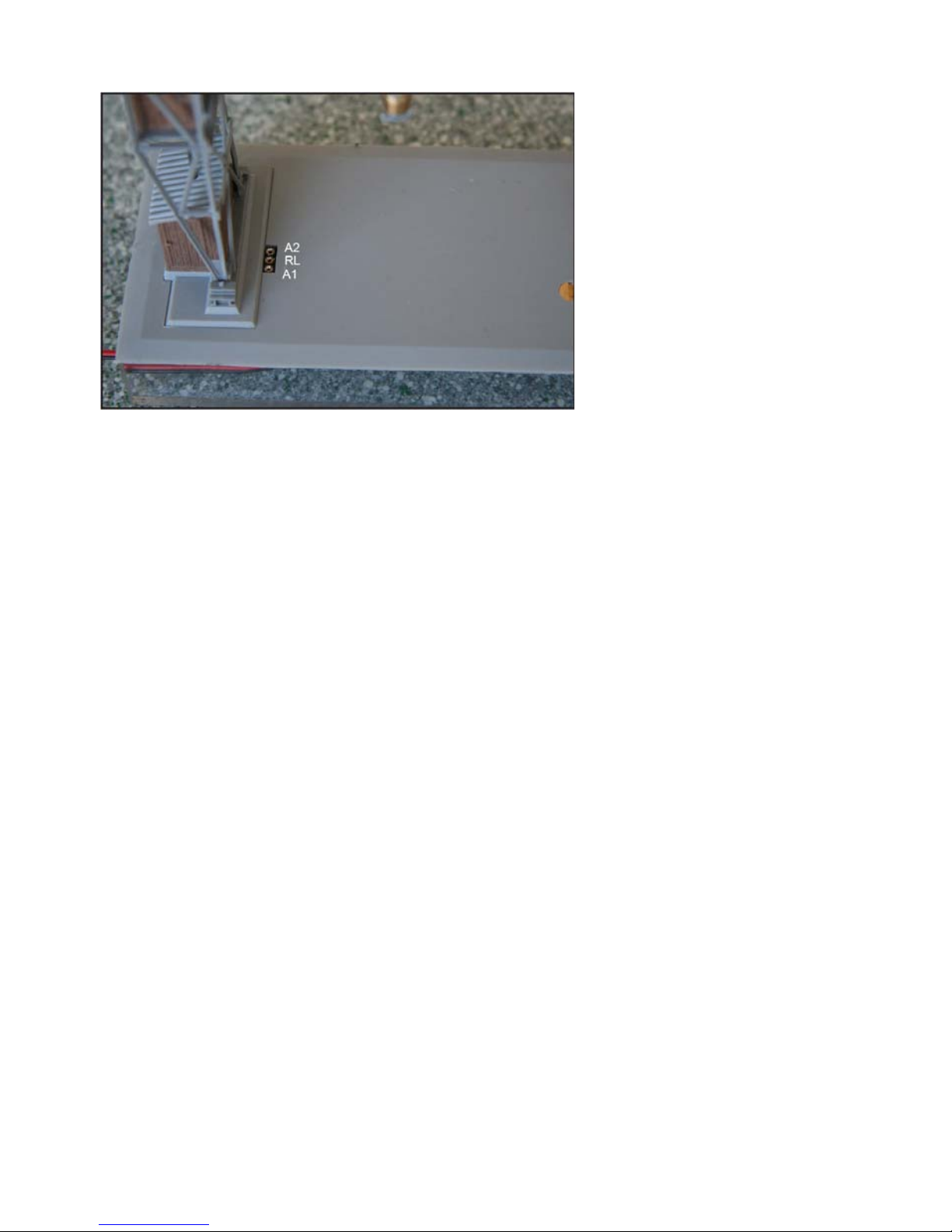
3
3 pole socket in the Base plate
The 3 pole socket provides outputs A1 and a2 as well as the common return RL. Loads such as
lighting, lifting magnet etc. can be connected here. The outputs can then be switched by keys 5 and 6
in analog operations and special function keys f1 and f2 in digital operations
Installation
Firstly saw a cutout of 124 x 53 mm in the layout’s base board under the shipping track. There is a
suitable template at the end of this description.
Attach sufficiently long cables to the appropriate connecting terminals.
Insert the gantry crane into the cutout by firstly passing the cables through it. You can use a
commercial adhesive to attach the base plate of the gantry crane on the layout board.
Operating
Analog Operation
After the crane is installed the keys and transformer are connected. Use a 16V~ model railway
transformer. Should you wish to operate loads on the A1 to A4 outputs connect them at this stage in
accordance with above connection allocation. The gantry crane is now operational.
The crane hook can be operated by keys 1 and 2 and the trolley by keys 3 and 4. Should the end
positions be reached without the respective motor being stopped the engine output is automatically
switched off (overload protection).
Note: The overload protection automatically switches the motor output off whenever the end positions
are reached, if the motor is not stopped.
Using Keys 5 to 8 outputs A1 to A4 can now also be controlled as described above.
For finer settings in the analog operations the crane decoder can be programmed with a digital cente r.
The rotating speeds for the 4 motor movements, the starting inertia with analog key press, as well as
the brake inertia when the key is released, can be adjusted.
Digital Operation
After the crane is installed connect the digital power (track power). Should you wish to operate loads
on the A1 to A4 outputs connect them at this stage in accordance with above connection allocation.
The gantry crane is now operational.
To operate the crane, call up locomotive address 3 on your digital center. Set locomotive address 3 to
DCC data format with 14 speed steps on the center (if possible) or operate address 3 in Motorola
format.
Attention: The crane decoder works only in 14 speed step mode!

4
If light function (f0) is switched off the crane hook can be controlled with the speed control. When light
function (f0) is switched on you can control the trolley with the speed control. The adjusted speed step
remains after switching the light function. If the end positions should be reached without having
stopped the relevant motor the motor output is automatically switched off (overload protection).
Note: The overload protection automatically switches the motor output off whenever the end positions
are reached, if the motor is not stopped.
By reversing the travel direction the speed is set to 0 and the motor output is reactivated (emergency
stop without starting/brake inertia).
If outputs A1 to A4 have loads attached they can be switched by special function keys f1 to f4. The
loads on A1 to A4 must operate on approximately +20V. The key terminals are not functional in the
digital operations.
Programming
In factory default state all decoder options are changed using configuration variables (CVs) according
to the DCC standard. The decoders can be pro grammed by an Intellibox, DCC Centre and Moto rola
Centre.
Programming with the Intellibox
Irrespective of the format to be driven later we recommend that the decoder be programmed via the
programming menu for DCC decoders.
The Intellibox supports DCC programming with a simple input menu. Long addresses do not have to
be laboriously calculated, they can be entered directly. The Intellibox automatically calculates the
values for CV17 and CV18.
For the exact process please read the appropriate chapter in the Intellibox manual.
Special case Motorola Locomotive addresses 80 to 255
In Motorola format the Intellibox supports an address range 255. Addresses 1 to 80 can also be
programmed easily using DCC programming mode. If an address above 80 is to be programmed, it
must, however, be done as described in the chapter “Programming with a Märklin Centre”.
After this programming technique CV 1 will be set to 0 and the decoder will use the Motorola address
higher than 80.
Programming of long Addresses without Pro gramming Menu
For programming with a centre which does not support prog ramming with an input menu, the value for
CV17 and CV18 must be calculated. Here is an example for programming the address 2000.
x Divide the addresses by 256 (2000:256 = 7 remainder 208).
x Take the result (7) and add it to 192.
x Program this value (199) into CV17.
x Program the remainder (208) into CV18.
x Important: Set Bit 5 of CV 29 to 1, so the decoder uses the long address.
Calculating the CV value
With CV29 and CV49 various characteristics of the decoder may be established.
The required values are easily calculated using the CV table and simple addition.
Example CV 49
Motorola off Value = 1
DCC on Value = 0
f1 toggle A1/A2 Value = 64
+20V on RL Value = 0
The Sum of all values is 65.
This value is programmed into CV 49.
Bit Function CV 49 Value
0 Motorola on
Motorola off
0
1
1 DCC on
DCC off
0
2
6 f1 switch A1 and f2 switch A2
f1 toggle A1/A2
0
64
7 +20V for Function outputs on RL (Base plate)
Expansion module supplies RL (Base plate)
0
128

5
Programming with a Märklin Center
With a Märklin center all CVs can be programmed, but not read.
Note: Before programming, the crane trolley must be driven into the center of the gantry.
1. Switch Center off and on.
2. Select the address of the decoder and switch the light on.
3. Change the direction of travel 5 times in quick succession, until the motor jerks briefly.
4. Set the speed controller to "zero".
5. Enter the nu m ber of the CV that is to be programmed.
6. Briefly operate the reversing switch. The motor jerks briefly.
7. Enter the desired value for CV e.g. a locomotive address.
8. Briefly operate reversing switch. The motor jerks briefly.
If further CVs are to be programmed repeat points 5-8.
If programming is to be terminated switch the center to "STOP" or set the address to "80" and briefly
operate the eversing switch.
Note: Since a Motorola digital center from Märklin only accepts inputs of 01 to 80, the value "0" must
be entered by entering the address as "80".
Page-Register for inputting CV-Numbers greater than 79
CV addresses larger than 79 can only be programmed with the help of the page register, CV66. If
CV66 has a value higher than 0, then the contents of CV66 times 64 will be added to every address
entered. The entered value must lie in the range 1 to 64.
When leaving the Motorola programming mode, the page register (CV66) is automatically reset to
zero.
Offset-Register for entering CV values greater than 79
CV values larger than 79 can only be programmed with the help of the offset register. The offset
register is CV65. If CV65 contains a value > 0, then all the following programmed values are
calculated by multiplying the contents of CV65 by 4 and adding the result to the entered value.
When leaving the Motorola programming mode the offset register (CV65) is automatically reset to
zero.
Example
CV49 is to be programmed with a value of 131, then CV65 must first be programmed with the value of 25.
Subsequently, CV49 can be programmed with a value of 31. The decoder places the value 4 * 25 + 31 into
CV49.
Note: When programming CV65 and CV66 the contents of the offset and page registers have no
effect.

6
Table of individual CVs (Configuration Variables)
CV Description Value Range Factory Default
1 Short Locomotive Address 1-127 3
2 Minimum Speed 1-63 5
3 Start Inertia 1-63 2
4 Brake Inertia 1-63 2
5 Maximum Speed
Must be greater than CV2
1-63 20
6 Maximum Motor Voltage
Must not be changed
1-255 64
7 Software Version
The processor used can be updated
- Varies
8 Manufacturer - 85
17
18
Long Locomotive Address
17 = High Byte
18 = Low Byte
1-9999
192-231
0-255
2000
199
208
29 Configuration of both motors in DCC standard
Bit 0=0 Driving direction not swapped
Bit 0=1 Driving direction swapped
Bit 1=0 14 Speed steps
Bit 5=0 Short Address (CV 1)
Bit 5=1 Long Address (CV 17/18)
Value
0 *
1
0 *
0 *
32
0-33 0
49 Decoder Configuration
Bit 0=0 Motorola on
Bit 0=1 Motorola off
Bit 1=0 DCC on
Bit 1=1 DCC off
Bit 6=0 f1 switches A1 and f2 switches A2
Bit 6=1 f1 toggles A1/A2 (switches between A1 and A2)
f1 off: A1 off und A2 on
f1 on: A1 on und A2 off
Bit 7=0 +20V for Function output RL on the base plate socket
Bit 7=1 Extension module provides RL for the base plate socket
Note: If the Motorola data format is switched off in bit 3 and the DCC data format is switched off
in bit 4, the decoder will not receive any more driving instructions and can only be programmed.
Value
0 *
1
0 *
2
0 *
64
0*
128
1-195 0
65 Motorola Programming Offset 0-255 0
67 Maximum Speed for Key 1 (Analog Operation) 0-255 40
68 Maximum Speed for Key 2 (Analog Operation) 0-255 40
69 Maximum Speed for Key 3 (Analog Operation) 0-255 50
70 Maximum Speed for Key 4 (Analog Operation) 0-255 50
71 Starting Inertia for Key 1 (Analog Operation) 0-255 5
72 Starting Inertia for Key 2 (Analog Operation) 0-255 5
73 Starting Inertia for Key 3 (Analog Operation) 0-255 5
74 Starting Inertia for Key 4 (Analog Operation) 0-255 5
75 Braking Inertia for Key 1 (Analog Operation) 0-255 1
76 Braking Inertia for Key 2 (Analog Operation) 0-255 1
77 Braking Inertia for Key 3 (Analog Operation) 0-255 1
78 Braking Inertia for Key 4 (Analog Operation) 0-255 1
79 Maximum Motor Voltage in Analog operation 0-255 180
98 Timed switching of Outputs A1 + A2
0 = both Outputs not timed
1 = only A1 timed switching
2 = only A2 timed switching
3 = A1 and A2 timed switching
0-3 3
99 Maximum ’On’ time in Seconds
for timed outputs as in CV 98
0-255 45
The factory default values are marked with an *.

7
Gantry Crane Template
Guarantee declaration
Each component is tested for its complete functionality before distribution. If a fault should arise within
the guarantee period of 2 years, we will repair the component free of charge upon production of proof
of purchase. The warranty claim is void if the damage was caused by inappropriate treatment.
The trade names mentioned are registered trade marks of the respective companies.

8
02045
8583-27
If you have any questions call us. Hotline times are:
Mon - Tue - Thu - Fri, 14:00-16:00 and Wednesdays 16:00-18:00
Our products are covered by a two year warrantee. If it is defective send decoder
along with the receipt of purchase to the following address:
Uhlenbrock Elektronik GmbH * Mercatorstr. 6 * 46244 Bottrop
Tel: 02045-8583-0 * Fax: 02045-8684-0 * www.uhlenbrock.de
 Loading...