

Page 1
Digital-Servo 81 310
Charateristics
• For Märklin oder DCC Digital systems and Analogue operation
• Integrated Digital decoder
• Switchable by locomotive functions, solenoid or proportional to speed setting
• Configurable turning speed
• Up to four configurable stop positions
• Rotation angle up to 180°
• Configured by DCC CV programming or by a Motorola Digital center
• With mounting material, cam levers and control wires
2 x 0.4 mm and 1 x 0.6 mm, length 100 mm
• Torque 2 Ncm
• Dimensions 20.0 x 17.6 x 8.0 mm
Description
The digital servo with the integrated digital decoder is suitable for installation in vehicles, as well as for use
in stationary working models. The quiet, smooth running spoils even the fastidious Model railroader. The
servo moves the item with the enclosed control wire. In vehicles for example, pantographs or doors can be
moved. In fixed items for example, it can move turnouts, signal semaphores, boom gates, water cranes and
gates.
With the enclosed mounting material the servo can be installed in many different positions.
Connection
The digital servo has two connecting wires which are connected in an analogue operation as shown below
or in digital operation to the track power from the digital center or a Booster.
Attention: Manual turning of the servo cam will destroy the servo!
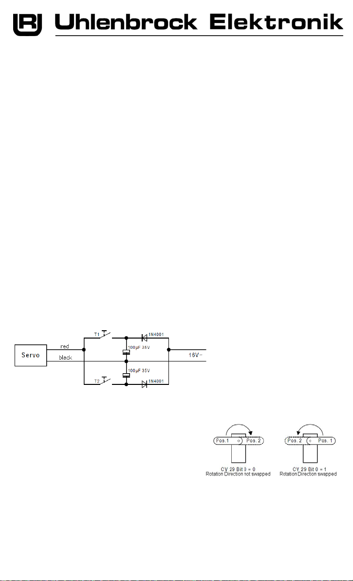
Example for connecting in Analogue Operation
Meaning for the connection:
Plus to red, Minus to black wire – the Servo moves to Position 1.
Plus to black, Minus to red wire – the Servo moves to Position 2.
Attention: The reversing pulse from a Märklin transformer will destroy the servo!
Analogue Operation
The Servo can be operated with DC or AC voltage between
10V und 20V. Depending on the polarity the servo moves
between two programmable end positions at a maximum
angle of 180°. These end positions can be programmed, for
use in an analogue system, with a digital center in CV261
for position 1 and CV262 for position 2 (see the section
“Programming “).
Bit 0 in CV 29 can be used to swap the rotation direction.
The servo operates for as long
as a key is pressed, up to the
stop position.
Important: Only one key can be
pressed at a time!
1
Page 2
Digital Operation
In the digital operation the servo can be controlled in five different operating modes. The appropriate
operating mode is specified in CV257 (see the section “Selection of Digital Format and Operating Mode”).
In all modes the operating speed between the end positions are adjustable (CV 258), as is a starting
delay (CV259). The brake delay is fixed
Up to four stop positions can be programmed in CVs 261 to 264. The value range is between 0 and 255
and corresponds to a total angle from 0 to 180°.
Bit 0 of CV29 can be used to swap the rotation direction in all operating modes (see Table “Calculating
the value for CV29 “).
The Locomotive address is either programmed in CV1 (short address DCC 1-127, Mot. 1-80) or in CVs 17
and 18 (long address DCC 128-9999). Bit 5 of CV29 determines if the short or the long address is to be
used (see Table “Calculating the value for CV29 “).
The Solenoid address (Operating modes 3 and 5) is always programmed into CVs 17 and 18 (only DCC
1-2000).
Operating Modes
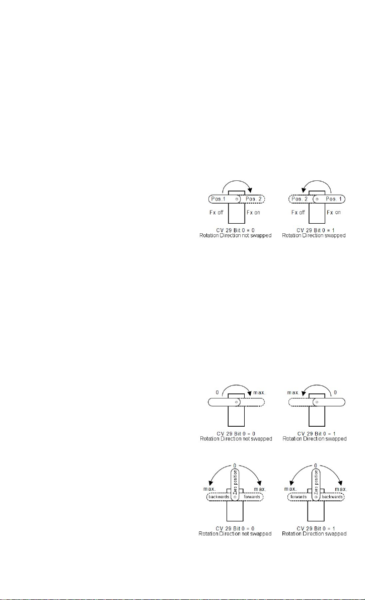
Operating Mode 1 – Control by Locomotive address and Spe cial function
The servo can be operated by any desired locomotive
special function of a programmable locomotive address
between two programmable stop positions through a
maximum angle of 180°.
If the locomotive special function is switched off, stop
position 1 from CV261 is approached. If the locomotive
special function is switched on, the stop position 2 from
CV262 is approached.
The locomotive special function number is entered into the CV265 (high order byte) and CV266 (low order
byte). If CV265 contains a value of 128 (factory setting) a value between 0 and 28 can be programmed into
CV266, where the value corresponds to the desired locomotive special function number f0 to f28.
If locomotive special functions between f29 and f32767 are to be used the values to be programmed into
CV265 and CV266 are calculated with the following formula:
Locomotive special function number = high order byte * 256 + low order byte
Example
The Servo is to be controlled by locomotive special function f300 of locomotive address 10.
Divide the locomotive special function number by 256 (300/256 = 1, remainder 44)
Enter the result (1) as the value of CV265.
Enter the remainder (44) as the value of CV 266.
The following CVs need to be programmed:
CV1 (short address) = 10, CV 265 = 1, CV 266 = 44
Operating Mode 2 - Control by Locomotive address and Speed St ep
The servo can be controlled proportional to the position
of the speed control from any locomotive address,
whereby speed step 0 is the extreme left of the servo’s
travel and the maximum speed step (14 or 28,
depending on the value of CV29) the extreme right
position of the servo’s travel. The desired end positions
are reached by the speed control over a maximum
angle of 180°.
Operating Mode 3 - Control by Locomotive address, Speed Step and Direction
The servo can be controlled proportional to the position
of the speed control from any locomotive address,
whereby speed step 0 brings the servo to its central
position. With the maximum speed step in the forward
direction driving the servo to its extreme right position,
and with the maximum speed step in reverse direction
to its extreme left position, the desired end positions
are reached by the speed control over a maximum
angle of 180°.
.
2
Page 3

Operating Mode 4 – Control by 1 Solenoid Address and 2 Stop Positions (DCC only)
Using one solenoid address the servo can travel
between two programmable stops through a maximum
angle of 180°.
When the solenoid address is switch to “round/red” stop
position 1 from CV261 is approached. When the
solenoid address is switch to “straight/green” stop
position 2 from CV262 is approached.
The solenoid address is programmed into CV17 (high order byte) and CV18 (low order byte) according to
the following formula:
Solenoid address = high order byte * 256 + low order byte
Example
Solenoid address 300 is to control the servo.
Divide the solenoid address by 256 (300/256 = 1, remainder 44)
Enter the result (1) as the value into CV17.
Enter the remainder (44) as the value into CV18.
The following CVs need to be programmed:
CV 17 = 1, CV 18 = 44
Operating Mode 5 - Control by 2 Solenoid Address and 4 Stop Positions (DCC only)
Using two solenoid addresses together the servo can
travel between four programmable stops through a
maximum angle of 180°.
When the first solenoid address is switched to
“round/red” the servo moves to stop position 1 from
CV261 and if it is switched to “straight/green” it moves
to stop position 2 from CV262. When the second
solenoid address is switched to “round/red” the servo
moves to stop position 3 from CV263 and if it is
switched to “straight/green” it moves to stop position 4 from CV264.
The first solenoid address is programmed into CV17 (high order byte) and CV18 (low order byte)
according the following formula:
Solenoid address = high order byte * 256 + low order byte
The second solenoid address corresponds to the first plus 1.
Example
Solenoid addresses 300 and 301 are to be used to control the Servo.
Divide the solenoid address by 256 (300/256 = 1, remainder 44)
Enter the result (1) as the value into CV17.
Enter the remainder (44) as the value into CV18.
The following CVs need to be programmed:
CV 17 = 1, CV 18 = 44
Since CV257 is set to operating mode 5 (Control by two Solenoid Address and four Stop Positions), the
next address (here 301) will control the servo stop positions 3 und 4.
Selection of Digital Format and Operating Mode
The settings for the digital servo are programmed into CV257, e.g. which data format is to be used and in
which mode the digital servo should.
Note: Only one of the five operations can be selected.
Calculating the value for CV257
The value to be entered is calculated from the CV-table by adding the values of the desired functions.
Example
The servo is to be controlled by one
solenoid address and to be used on the
DCC format.
One solenoid address Value = 4
Only DCC operation Value = 64
The Sum of the values is 68.
Value 68 is programmed into CV 257.
Note: If the functions “Only DCC operation” and “Only Motorola operation” are both programmed the Digital
servo will not operate and can only be programmed.
Function CV257 Value
Mode 1 – Locomotive address and Special function 1
Mode 2 – Locomotive address and Speed Step 2
Mode 3 – Locomotive address and Speed Step 3
Mode 4 – One Solenoid Address and two Stops 4*
Mode 5 – Two Solenoid Address and four Stops 5
Only DCC operation 64*
Only Motorola operation 128
3
Page 4

Programming
The basis for setting up all the digital servo’s options is the Configuration Variables, CVs for short. The
Digital servo can be programmed with Intellibox, DCC and Motorola Center.
Note: During Programming the servo moves to the central position. It moves slightly around this position
during every read and write operation.
Programming with the Intellibox
The Intellibox supports DCC programming with a user friendly embedded menu. Long addresses do not
need to be laboriously calculated. They can be entered directly. The Intellibox automatically calculates the
values for CV17aund CV18 and sets Bit 5 in CV29 so that the long address is actually used. In exactly the
same way as it can be read. See the appropriate chapter in the Intellibox Manual.
Programming with DCC devices
Use the programming menu of your DCC Center to program the servo CVs by Register, direct or Page
programming for reading and programming. The precise procedure is found in the Manual for your Center.
Help Register for “little” DCC Centers with max. 99 CVs
When using DCC Center which can only program a maximum of 99 CVs you use a Help register. If CV32
is programmed with a value of 1, 2, 3 or 4, you can use CVs 96, 97, 98 und 99 to program CVs above 256
with the following procedure:
CV 32 = 0 – help register inactive
CV 32 = 1 - CVs 96-99 program CVs 257-260
CV 32 = 2 - CVs 96-99 program CVs 261-264
CV 32 = 3 - CVs 96-99 program CVs 265-268
CV 32 = 4 - CVs 96-99 program CVs 269-272
Programming of long Addresses without Programming Menu
If the programming is done with a center which does not have an embedded programming menu the values
for CV17 and CV18 must be calculated. This shows how to program address 2000.
Divide the address value by 256 (2000/256 = 7 remainder 208).
Take the result (7) and add 192 to it.
Enter this result (199) as the value for CV17.
Enter the remainder (208) as the value for CV18.
Important: Set Bit 5 of CV29 to 1 so that the decoder actually uses the long address
Main Line Programming
The decoder can be programmed using locomotive main line programming (POM) in all its operating
modes. If the decoder is in operating mode 4 or 5 (controlled by solenoid address) the solenoid address
must be used as the “locomotive address” of the POM-command. The two CVs can then not be altered.
Attention: When main line programming, please consider when programming CVs smaller than 257 that
perhaps an existing locomotive with same address can unintentionally have its CVs programmed. For this
reason use main line programming only to change the stop positions of the servos (CV 261-264). Usually
locomotive decoders do not use these CVs.
Calculating the value for CV29 (DCC Configuration)
Example
The Servo is be controlled by a Locomotive
address in DCC format with 28 speed steps.
The address to be used is a long address from
CV 17/18.
DCC 28 speed steps Value = 2
Use a long address Value = 32
The Sum of the Values is 34.
This value is factory preset to CV29.
Programming with a Märklin Center
With a Märklin center all CVs can be programmed, but not read.
1. Switch Center off and on.
2. Select the address of the digital servo.
3. Operate the direction change-over 5 times in quick succession.
4. Set the speed controller to "zero". The servo moves sligh tl y.
5. Enter the number of the CV that are to be programmed.
6. Briefly operate the direction change-over. The servo moves slightly.
7. Enter the desired value for CV e.g. a locomotive address.
8. Briefly operate the direction change-over. The servo moves slightly.
Bit Function CV29 Value
Rotation direction not swapped
0
Rotation direction swapped
DCC 14 Speed steps
1
DCC 28 Speed steps
Only digital operation
2
Digital/Analogue automatic
Use short address from CV1
5
Use long address from CV 17/18
2*
32*
0
1
0
0
4
0
4
Page 5

If further CVs are to be programmed repeat points 5-8.
If programming is to be terminated switch the center to "STOP" or set the address to "80" and briefly
operate the direction change-over.
Note: Since a Motorola digital center from Märklin only accepts inputs of 01 to 80, the value "0" must be
added by entering the address as "80".
Page-Register inputting of CV-Numbers greater than 256
If CVs above 256 are to be programmed then for this a 4 must be programmed into the CV66 (page
register). Now CVs 257 to 272 can be programmed using CVs 1 to 16.
CV66 = 0, CVs 1 to 29 are programmed directly.
CV66 = 4, CVs 257 to 272 are programmed with CVs 1 to 16.
The value of CVs 261 to 264 for the four possible stop positions, whose value is larger than 80, is internally
automatically multiplied by 4, so that the input values used are 0-63.
Example
CV261 is to have a stop position 1 set to a value of 200:
CV 66 = 4 (CVs 1 to 16 are to program CVs 257 to 272)
CV 5 = 50 (CV5 now corresponds to CV261 and 50*4 = 200 is the desired value 200)
Offset-Register for inputting of CV-Value greater then 79 (only for CV257 and CV265)
If CV values larger than 79 are to be programmed into the CV257 or CV265, then CV65 (offset register)
must be programmed larger than 0. For all following programming processes the value from CV65 is
automatically multiplied by 4 and added to the given value and programmed into the appropriate CV.
When leaving Motorola, programming the offset register (CV65) is automatically set back to zero.
Example
CV257 is to be programmed to the function “Only Motorola Operation“ (Value 128).
CV66 = 4 (CVs 1-16 are used to program CVs 257-272)
CV65 = 25 (the following values are added to 25*4 = 100)
CV1 = 28 (CV1 now represents CV257 and 28+100 = 128 is the new value 128)
Note: If the digital servo is operating in mode 4 or 5 (Controlled by solenoid addresses) the Motorola
programming is blocked. The operating mode of the Servos must be changed with a DCC center, before it
can be programmed with a Motorola center.
Programming Protection (DCC and Motorola)
If several Digital servos in a model (e.g. multi-bay locomotive shed) are to be controlled with the same
locomotive address, but via different locomotive functions, the “decoder lock” function (programming
protection) can be used for programming. Before installing the Digital servos, connect it to the programming
track and program the locomotive address (CV1) and program CV16 with an index number which is
different for each installed servo.
If the CVs of an installed servo is to be changed, then program CV15 with the index number of the servo
that is to be programmed.
Note: The CVs of a Servo can only be programmed if the value in CV15 is the same as that in CV16. The
CV15 however can always be programmed. Afterwards only the CVs of this servo are changed by CV
programming (POM) and not the CVs of the other servo.
Table of CVs (Configuration Variables) of the Digital servos
CV Description Value range
Short Locomotive address
1
is only used when CV29 Bit 5=0 (factory setting)
Software version (The processor used can be updated)
7
Manufacturer ID
8
Decoder Lock (Programming protection)
15
Decoder Lock Index Number
16
Long address (1-9999) or Solenoid address (1-2000)
17
17 = Long address high byte
18
18 = Long address low byte
The long address is only used when CV29 Bit 5=1
DCC 1-127
Mot 1-80
- varies
- 85
0-255 0
0-255 0
192-231
0-255
Factory
default
3
0
1
5
Page 6

CV Description Value range
Configuration DCC Standard
29
Bit 0=0 Normal driving direction
Bit 0=1 Reversed driving direction
Bit 1=0 14 speed steps
Bit 1=1 28 speed steps
Bit 2=0 only digital operation
Bit 2=1 auto digital/analog detection
Bit 5=0 Short Address (CV 1)
Bit 5=1 Long Address (CV 17/18)
Index Register for “small” DCC Centers
32
0 = Help register inactive
1 = CVs 96-99 program CVs 257-260
2 = CVs 96-99 program CVs 261-264
3 = CVs 96-99 program CVs 265-268
4 = CVs 96-99 program CVs 269-272
Offset Register
65
for CV programming with a Motorola Center
Page Register
66
for CV programming with a Motorola Center
96-99
The factory default values are marked with *.
Index Register for “small” DCC Centers
96 for CVs 257,261, 265, 269
97 for CVs 258,262, 266, 270
98 for CVs 259,263, 267, 271
99 for CVs 260,263, 268, 272
for this the appropriate value must be set in CV32
Selection of Operating Mode and Digital Format
257
Control by locomotive address and special function
Control by locomotive address and speed steps
Control by locomotive address, speed step and direction
Control by one solenoid address with 2 stop positions
Control by two solenoid address with 4 stop positions
DCC operation only
Motorola operation only
Rotation Speed
258
Acceleration delay (Inertia)
259
Decoder Reset
260
Stop Position 1
261
Stop Position 2
262
Stop Position 3
263
Stop Position 4
264
Locomotive special function number
265
265 = high order byte
266
266 = low order byte
Value
0 *
1
0
2 *
0
4 *
0 *
32
Value
1 *
2
3
4
5
64
128
0-255 6
0-4 0
0-63 0
0, 4 0
- -
0-255 1
0-63 10
0-63 2
0, 1 0
0-255 15
0-255 220
0-255 100
0-255 150
0-128
0-255
Factory
default
128
1
Guarantee declaration
Each component is tested for its complete functionality before distribution. If a fault should arise within the
guarantee period of 2 years, we will repair the component free of charge upon production of proof of
purchase. The warranty claim is void if the damage was caused by inappropriate treatment.
The trade names mentioned are registered trade marks of the respective companies.
Our contact Details:
Service
In the event of a defect or failure send the unit
together with the invoice and a short
description of the fault back to us for repair.
We are available if you have any questions!
Your direct line to a technician:
Mon - Tue - Thu – Fri, 14:00~16:00 and Wed 16:00~18:00
Hotline
0 20 45 - 85 83 27
6
Uhlenbrock Elektronik GmbH
Mercatorstr. 6
D-46244 Bottrop
Made in Germany
Electronic devices do not
belong in household rubbish
 Loading...