

Page 1

Servo decoder 67 800
For connection 4 Servos
Characteristics
• For Märklin and DCC Digital systems
• Switchable like a solenoid decoder
• Switching address for each servo freely selectable
• Adjustable stop positions
• Adjustable rotating speed
• 4 stopping positions via 2 addresses in the DCC operation
• Backlash function, e.g. for boom gates or semaphore signals
• Configurable via the turnout keys of digital systems
or by DCC CV programming
• Powered from the track or separate transformer
• Very low power usage by integrated regulator
• Servo output with overload protection
Description
The servo decoder allows you to use Servos, as commonly employed in modeling, to solve
mechanical control problems on the model railway layout. For example, with the appropriate
mechanics the Servos can change turnout positions, move water cranes in, open doors of
locomotive sheds, operate boom gates and much more.
Up to four Servos can be connected to a servo decoder and operated independently of each
other. The servo decoder works like a turnout decoder and in a digital system is assigned a
solenoid address for each servo. By using digital systems, the solenoid controlling the servo
can be brought to two stop positions. The servo decoder operates with all DCC and Motorola
Digital systems.
The Servos’ stops for the two solenoid positions "red" and "green" can be independently
configured. The speed with which the servo moves between the two stops can also be
adjusted.
For special applications each of the attached servos can have two additional independent
stops by assigning two additional solenoid addresses. This way mechanical items like water
cranes can be moved between four positions via two solenoid addresses.
The servo decoder also has a “rocker” function which can be used for boom gates or
semaphore signals. If the servo reaches a stop it then bounces a little before it stops
completely. The rocker movement amplitude and speed can be adjusted.
1 Address, both stops and the rotating speed for each servo are separately setup with simple
key programming from Motorola and DCC centers.
In the case of use of a DCC center like the Intellibox all parameters can be programmed by
CV programming. That way, 2 addresses, their stops, the rotating speed and the rocker
function can be separately setup for each servo.
Page 2
Installation of Servo decoders 67 800
Connecting the Servo decoder
The terminals labeled “Gleis” (track) are connected with the track terminals of a DCC or
Motorola Digital center. In this case the decoder is supplied via the track power.
Note: Since most Servos move uncontrolled, when supply voltage is switched on (this is a
servo characteristic and is not produced by the servo decoder), we recommend that the
decoder is also connected to a 16V model railway transformer via the "trafo" terminals. The
uncontrolled movements of the Servos then only occur when the entire layout is switched on.
Connecting the Servos to the Servo Decoder
Each servo decoder has four 3-pin headers for connecting a maximum of four Servos. The
Servo’s plugs are plugged onto the appropriate header so that the earth wire (usually black
or brown) is at the front edge of the circuit board.
Header pin assignment
Earth - PCB front edge
5V - middle
Control wire - back
Tip: If the distance from the servo to the servo decoder is too far you can extend the lead
without any difficulty. Servo cables with plug and socket are available in specialized
electronics outlets.
Programming
From a DCC center, the decoder can be programmed by keys and solenoid instruction or by
using CV programming.
With key programming not all items can be used.
Item Key programming CV Programming
Data format X X
Addresses 1 2
Stop positions 2 4
Switching time X X
Whip function - X
Selection whether the servo is always to be switched
on or only during servo movement
Programming by Key and Solenoid Command
All settings for the stops and the servo speed are easily set by the digital center, or another
control device, with which one can control solenoids.
The desired servos should be connected to the outputs that are to be programmed since the
servo decoder acknowledges the setting of the servo parameters, during programming, with
a movement of the respective servo.
1. Activating Programming Mode
Press the key on the decoder and keep it pressed. The control LED blinks.
2. Selecting Data Format
The LED blinks alternately at flashing rate A and flashing rate B for 5 seconds in each case.
Meaning:
Blinking rate A = __ __ __ = selection DCC format
Blinking rate B = _ _ _ _ _ _ = selection Motorola format
If the key is released during the appropriate blinking rate then the appropriate data format is
selected.
Note: If the decoder no longer reacts to key inputs from the input device, the wrong data
format was selected! Programming must be repeated.
- X
Page 3

3. Specify servo output to progra m
When the key is released the servo on connector 1 briefly moves back and forth. If the key is
pressed again the servo at connector 2 briefly moves back and forth. Further operation
changes to output 3 and 4. If the key is then operated again, programming mode is
terminated.
Operate the key repeatedly until the servo on the output to be programmed moves briefly.
4. Specifying the solenoid address for the selected servo output
On digital center or another control device which can switch solenoids, operate one of the
two keys (red or green) which are to move this servo later. The servo decoder acknowledges
the key press as the servo briefly moves back and forth.
5. Selecting solenoid keys for [+] and [-] keys
In order to be able to set up stops and the speed of the servo during programming, two keys
must be specified which will be used as [+] and [-] key.
From the digital center, or another control device which can switch solenoids, press the key
which is to be used as [+]-key. The solenoid address of this key must not be the same as the
previously selected solenoid address. The servo decoder acknowledges the key press by
briefly moving the servo back and forth.
In the same way, the key which is to be the [-]-key is determined.
Note: After programming, this allocation is deleted so that these keys can be used on the
layout as normal.
6. Setting the stop positions of the Servos
Using the address setup in step 4, the servo can now be moved to stop position “red” with
the red solenoid key. With the help of the [+] and [-] keys, specified in step 5, the stop
position of the Servos is adjusted accordingly. For this the [+] or [-]-key is repeatedly pressed
until the desired retaining position is reached. With the green solenoid move the servo to the
stop position "green" as described above.
When desired positions are fixed, the servo must be switched to the "red" and "green" sto p
positions 3 times (thus red-green-red-green-red-green) without changing the setting, in order
to go to the next programming step (keys in accordance with step 4).
7. Setting the speed of the Servos
The servo now independently moves back and forth with the set speed between the two stop
positions. The speed of the movement can be increased or decreased with the [+]and [-]
keys, specified in step 5.
8. Terminate Programming
When the desired speed is adjusted, one of the two keys which change the servo position is
operated, (keys in accordance with step 4).
Programming for this servo output is complete and the servo decoder is ready for the
programming of the next output. The selected settings are permanently stored.
Note: If the programming is terminated prematurely, as if the track power is switched off,
then the selected settings are stored.
Page 4
CV Programming with DCC Devices
p
The decoder can be programmed with the Intellibox and any DCC center that permits 3 digit
numerical values. Use the programming menu of your DCC center to select and program
the decoder CVs. The exact process will be outlined in the center’s manual.
Connection of the servo decoder for programming
For programming the servo decoder it must be individually connected to a programming
track. The desired servos are connected to outputs which are to be programmed.
Configuration of the servo decoder
CV 119 is used to specify different decoder settings.
If the power on the different servo outputs is always switched on or only during servo
operation and if the operating mode is Motorola or DCC:
The entered value is calculated from the
CV table in which the values of the desired
functions are added.
Example
Output 1 power always on value = 1
Output 2 power always on value = 2
Output 3 power always on value = 4
Output 4 power always on value = 8
Operating mode DCC value = 0
Sum of all values is always 15.
This value is preset in CV 119 by the
factory.
Configuration of the Servo Outputs
Bit Function of CV 119 Value
0 Power output 1
only switched on during servo operation
always switched on
1 Power output 2
only switched on during servo operation
always switched on
2 Power output 3
only switched on during servo operation
always switched on
3 Power output 4
only switched on during servo operation
always switched on
7 Operating mode
DCC
Motorola
0
1*
0
2*
0
4*
0
8*
0
128*
Note: In the following we always refer to the CVs for the servo output 1.
The CVs for out
uts 2 to 4 can be taken from the CV table.
Address 1 and 2 (CV 120 and 121, 160 and 161)
The addresses for each servo output can be freely selected. The valid range of address is
1-2048.
The servo is brought to the stop by the Address 1 in accordance with CV122 (red) and
CV123 (green).
Address 2 brings the servo to stop positions in accordance with CV162 (red) and CV163
(green).
Note: Address 2 can be configured by CV programming.
Addresses to 255 can be entered directly as values in the CV for the Low byte (e.g.
CV121). CV for the High byte (e.g. CV 120) remains at value 0 (factory setting).
Addresses from 256 the values for the High byte and the Low byte must be calculated. For
example, programming of the address 2000 is as follows.
• Divide the address value by 256 (2000/256 = 7 remainder of 208).
• Register the integer result (7) as value in CV for the High byte (e.g. CV 120).
• Register the remainder (208) as value in CV for the Low byte (e.g. CV 121).
Setting Stop positions (CV 122 and 123, 162 and 163)
The setting of the stops is done by numerical values between 0 and 127.
CV value = 0 maximum value for stops 1 and 3 (CV 122, 162)
CV value = 127 maximum value for stops 2 and 4 (CV 123, 163)
Setting time (CV 124)
Time constant by which servo position is incremented or decremented in 1 ms steps.
Process time = (difference between "red" and "green" values) * setting time * 1 ms
Setting time = (desired procedure time in seconds) * 1000 difference of the values for
retaining position "red" and "green"
Page 5
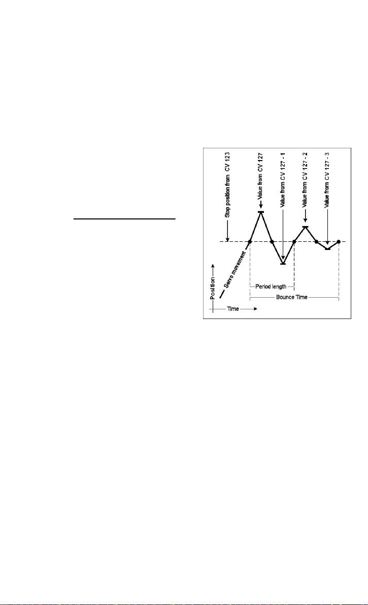
Bounce function (CV 125 to 128)
For both stops of the 1st Address of all four servo outputs, the bounce function can be
activated as it appears in boom gates and semaphore signals. For this the bounce distance
must not be 0 in CV 125 and CV 127.
Attention: In this case the programmed stop position of the Servo must be less than or
equal to the end stop minus the bounce distance.
Note: The stops for the 2nd Address are then no longer used.
With the bounce function active, the servo will, after reaching the respective "red" or "green"
stop, be beyond the stop by the amount of the bounce distance.
Now the motion direction is reversed and the servo again proceeds beyond the stop.
However this time only by the bounce distance minus 1.
With every subsequent reversal of direction that the servo movement approaches the
desired stop, the bounce distance is reduced by
one in each case.
After several movements the bounce distance is
0 and the Servo’s stop is reached.
The period length of the bounce function is set by
the bounce time in CV 126 and CV 128:
Bounce time =
Example
In this example the bounce amplitude was set to
"green” (CV 127) to the value 4.
The first bounce corresponds exactly to this
value. With each successive bounce the value is
reduced by 1.
Note: The programmed stop of the Servos plus
the bounce amplitude must be less than or equal
to the end stop (= possible position).
period length
4 * bounce amplitude * 1 ms
Technical data
Addresses: 2
Address range: 1-2048 digital
Format: DCC, Motorola
Servo outputs: 700 mA each
Total load: 700 mA
Accessories
Transformer 45 VA Part No. 20 040
The transformer has an output voltage of 16 V. A maximum current of 2.8 A. The
transformer has 2 quick connect terminals on the low voltage side.
Servos
With accessories, mounting material and control wire, 2 x 0.4 mm and 1 x 0.6 mm, length
100 mm.
Mini servo Part No. 81 410
Used in restricted space conditions, for applications which do not require high torque.
Size 20.0 x 17.6 x 8.0 mm, torque 4 Ncm.
Standard servo Part No. 81 420
For general use, e.g. turnouts. Size 22.2 x 20.0 x 11.1 mm, torque 13 Ncm.
Precision servo Part No. 81 430
Very quiet and precise. Size 22.2 x 21.3 x 11.1 mm, torque 14 Ncm.
Page 6

CV Table (Configuration Variables) of Servo decoder 67 800
Configuration of Decoders
Value
CV Description
112 Software version (the processor used can be updated) - varies
113 Manufacturer code - 85
119 Decoder Configuration
Bit 0=0 Power Output 1 only on during servo movement
Bit 0=1 Power Output 1 always
Bit 1=0 Power Output 1 only on during servo movement
Bit 1=1 Power Output 1 always
Bit 2=0 Power Output 1 only on during servo movement
Bit 2=1 Power Output 1 always
Bit 3=0 Power Output 1 only on during servo movement
Bit 3=1 Power Output 1 always
Bit 4-6 Not used
Bit 7=0 DCC operation
Bit 7=1 Motorola Operation
The asterisk * denotes the factory default value
Value
0
1*
0
2*
0
4*
0
8*
-
0*
128
Factory
Range
Default
0-255 15
Configuration of Servo outputs
CV for servo output Factory defaults
1 2 3 4
120 130 140 150 1. Address high byte 0-8 0 0 0 0
121 131 141 151 1. Address low byte 0-255 1* 3* 5* 7*
122 132 142 152 Stop position “red” Address 1 0-127 30 30 30 30
123 133 143 153 Stop position “green” Address 1 0-127 95 95 95 95
124 134 144 154 Switchover time 0-255 40 40 40 40
125 135 145 155 Bounce distance setting “red” 0-127 0 0 0 0
126 136 146 156 Bounce duration setting “red” 0-255 0 0 0 0
127 137 147 157 Bounce distance setting “green” 0-127 0 0 0 0
128 138 148 158 Bounce duration setting “green” 0-255 0 0 0 0
160 170 180 190 2. Address high byte 0-8 0 0 0 0
161 171 181 191 2. Address low byte 0-255 0 0 0 0
162 172 182 192 Stop position “red” Address 2 0-127 0 0 0 0
163 173 183 193 Stop position “green” Address 2 0-127 0 0 0 0
*) When a Motorola center is used the factory programmed addresses are not usable and must be adjusted by the user via
key programming.
Description Value
Range
1 2 3 4
Guarantee declaration
Each component is tested for its complete functionality before distribution. If a fault should
arise within the guarantee period of 2 years, we will repair the component free of charge
upon production of proof of purchase. The warranty claim is void if the damage was caused
by inappropriate treatment.
Please note that, according to EMV regulation the component may only be installed in
vehicles which carry the CE logo.
The trade names mentioned are registered trade marks of the respective companies.
Our contact Details:
In the event of a defect or failure send the unit together
with the invoice and a short description of the fault back
We are available if you have any questions!
Your direct line to a technician:
Mon - Tue - Thu – Fri, 14:00~16:00 and Wed 16:00~18:00
Service
to us for repair.
Hotline
0 20 45 - 85 83 27
Uhlenbrock Elektronik GmbH
Mercatorstr. 6
D-46244 Bottrop
Made in Germany
Electronic devices do not
belong in household rubbish
Not suitable for children
under age 10.
Part No. 67 800
 Loading...