

Page 1
The shortest connection
between technology
and pleasure
Manual for Software Version 1.0
Page 2

Intellibox II
2
Page 3

Intellibox II
Table of Contents
1. The Digital Center Intellibox II...................................................................................6
1.1 Description............................................................................................................................ 6
1.2 Quick guide........................................................................................................................... 9
1.3 Overview of the Commands................................................................................................ 10
1.4 Technical Data.................................................................................................................... 11
2. The Intellibox II Connections...................................................................................12
2.1 Definition of the individual Sockets..................................................................................... 12
2.2 Connecting Transformer, Track and Programming Track................................................... 12
2.3 Connecting LocoNet ........................................................................................................... 13
2.4 USB Computer Interface.....................................................................................................13
2.5 Connecting DCC Boosters.................................................................................................. 14
2.6 Connecting Märklin Boosters.............................................................................................. 14
2.7 Connecting s88 Modules .................................................................................................... 15
2.8 Connecting IRIS Receivers................................................................................................. 15
3. The Operating Elements.......................................................................................... 17
3.1 Overview of the Operating Elements.................................................................................. 17
3.2 The Display with the Display keys ...................................................................................... 18
3.3 The Controller ..................................................................................................................... 19
3.4 Menu Operation.................................................................................................................. 19
3.5 Entry of Numerals ............................................................................................................... 21
3.6 Entry of Names ................................................................................................................... 21
4. Basic Settings Menu ................................................................................................23
4.1 Menu Item Operation.......................................................................................................... 23
4.1.1 Speed Display.......................................................................................................... 23
4.1.2 Throttle..................................................................................................................... 25
4.2 “Language” Submenu ......................................................................................................... 27
4.3 ”Locomotive Data Format” Menu ........................................................................................ 28
4.4 “Turnout settings” Menu......................................................................................................29
4.4.1 General Data format................................................................................................. 29
4.4.2 Switching Times....................................................................................................... 30
4.5 “Hand Controller” Menu ......................................................................................................31
4.6 “Display” Menu....................................................................................................................32
4.7 “Programming Track” Menu................................................................................................ 34
4.8 “Interface” Menu.................................................................................................................. 35
4.9 “s88 Setting” Menu.............................................................................................................. 35
4.10 “Special Options” Menu .................................................................................................... 37
4.11 “Software-Version” Menu.................................................................................................. 38
4.12 “Start Mode” Menu............................................................................................................ 38
4.13 “Database” Menu .............................................................................................................. 39
4.14 “Reset” Menu .................................................................................................................... 41
5. The Control Desk......................................................................................................43
5.1 Operating Elements ............................................................................................................ 43
5.2 Locomotive Addresses und Names.................................................................................... 44
5.2.1 Locomotive selection................................................................................................ 45
5.3 Throttle................................................................................................................................45
5.4 Light and Special functions.................................................................................................46
5.5 The LokPosi Display........................................................................................................... 47
5.6 The Loco Menu................................................................................................................... 48
5.6.1 Multi-traction............................................................................................................. 48
5.6.2 Last called up Locomotive........................................................................................ 52
5.6.3 Controlling All Functions........................................................................................... 53
5.6.4 Dispatching Locomotives ......................................................................................... 55
3
Page 4

Intellibox II
5.6.5 Edit a Loco dataset................................................................................................... 56
5.6.6 FRED Hand Controller ............................................................................................. 66
6. The Switch Panel Mode............................................................................................69
6.1 Description.......................................................................................................................... 69
6.2 Select Switch Panel Mode.................................................................................................. 69
6.3 Operating a Switch Panel ................................................................................................... 70
6.4 Configuring the Switching times.......................................................................................... 71
6.5 Select a Switch Panel......................................................................................................... 71
6.6 Setup and Edit a Switch Panel............................................................................................ 72
6.6.1 Setup a new Switch Panel........................................................................................ 72
6.6.2 Edit Switch Panel ..................................................................................................... 74
6.6.3 Delete Switch Panel................................................................................................. 76
6.6.4 Switch Address Display on/off.................................................................................. 77
6.7 Set Name, Symbol and Data format of Solenoid addresses............................................... 78
7. The Route Mode .......................................................................................................81
7.1 Description.......................................................................................................................... 81
7.2 Selecting Route Mode......................................................................................................... 81
7.3 Selecting a Route Group.....................................................................................................81
7.4 Switching Routes................................................................................................................ 82
7.5 Entering and Changing Route Groups................................................................................ 83
7.5.1 Entering a new Route............................................................................................... 83
7.5.2 Change a Route Group............................................................................................ 85
7.5.3 Delete a Route Group .............................................................................................. 86
7.6 Programming Routes..........................................................................................................87
7.7 Using Routes from an External Device............................................................................... 97
7.8 Automatically activate a Route when the Intellibox starts up............................................ 100
7.9 Processing two or more Routes in succession................................................................. 101
8. The Feedback Mode...............................................................................................104
8.1 LocoNet Feedbacks.......................................................................................................... 104
8.2 s88-Feedback ................................................................................................................... 104
8.3 Selecting a Feedback Module........................................................................................... 104
8.4 The Display....................................................................................................................... 105
8.5 Selecting a Feedback Group ............................................................................................ 106
8.6 Adding and Changing Feedback Groups.......................................................................... 106
8.7 Setting the Name and Symbol of a Feedback .................................................................. 113
8.8 Triggering Feedback Message ......................................................................................... 115
9. The LISSY Mode .....................................................................................................116
9.1 Description........................................................................................................................ 116
9.2 Selecting LISSY Mode...................................................................................................... 116
9.3 The Display in LISSY Mode.............................................................................................. 116
9.3 The Display in LISSY Mode.............................................................................................. 117
9.4 Selecting the Displayed Group ......................................................................................... 117
9.5 Adding a new or Changing a Group.................................................................................. 118
9.5.1 Adding a new Group............................................................................................... 118
9.5.2 Changing a Group.................................................................................................. 120
9.5.3 Deleting a Group.................................................................................................... 122
9.5.4 Switching the Address display on/off...................................................................... 123
9.6 Assigning a Name to a Train Category and LISSY Receiver............................................ 124
9.7 DirectDrive........................................................................................................................ 126
10. The Infrared Remote Control IRIS.......................................................................127
10.1 Description of the Infrared Remote Control .................................................................... 127
10.1.1 Function Mode...................................................................................................... 127
10.1.2 Operating controls................................................................................................ 127
10.1.3 Locomotive Control .............................................................................................. 128
4
Page 5

10.1.4 Solenoid control.................................................................................................... 129
10.1.5 Activating a Route................................................................................................ 131
10.1.6 Power on/off......................................................................................................... 131
10.2 Intellibox Display Mode IRIS........................................................................................... 131
10.2.1 Selecting IRIS Mode............................................................................................. 131
10.2.2 Selecting the Transmission Channel.................................................................... 132
10.2.3 The Displays......................................................................................................... 132
Intellibox II
11. Model Time Clock.................................................................................................136
11.1 Description...................................................................................................................... 136
11.2 Selecting the Clock Mode............................................................................................... 136
11.3 Clock Settings................................................................................................................. 136
11.3.1 Special Settings.................................................................................................... 137
12. The Programming Mode ......................................................................................140
12.1 Programming Track ........................................................................................................ 140
12.2 Activating Programming Mode........................................................................................ 140
12.3 Programming of DCC and Multi-protocol Decoders........................................................ 141
12.3.1 Reading and programming CV Plain text............................................................. 141
12.3.2 Programming and reading individual CVs............................................................ 143
12.3.3 Mainline Programming ......................................................................................... 146
12.3.4 Register programming and reading...................................................................... 147
12.3.5 Paged programming and reading......................................................................... 147
12.3.6 Error message during Programming of DCC Decoders....................................... 147
12.4 Programming of Märklin Motorola or mfx Decoders ....................................................... 148
13. LocoNet Programming.........................................................................................150
14. The Interface.........................................................................................................154
14.1 Interface Characteristics................................................................................................. 154
14.2 Interface in Betrieb nehmen............................................................................................ 154
14.3 Communication PC - LocoNet (only for Experts)............................................................ 154
15. Operation as Auxiliary Device.............................................................................155
15.1 Operation ........................................................................................................................ 155
15.2 Setting the Operating Mode............................................................................................ 155
15.3 Connect as Auxiliary Device........................................................................................... 155
16. Software Update...................................................................................................157
Appendix.....................................................................................................................158
List of Special options............................................................................................................. 159
Converting bits to bytes .......................................................................................................... 161
Module address table for feedback channels ......................................................................... 163
Coding table for solenoid decoder.......................................................................................... 164
Tips and Tricks........................................................................................................................ 165
HOTLINE ................................................................................................................................ 168
5
Page 6

Intellibox II
1. The Digital Center Intellibox II
The Intellibox II is not only a Digital Center, but a complete S ystem in a Box. It has all the
functions which previously one had to labouriously assembled, and with all that it is
efficient and compact.
With the Intellibox II it does not matter whether you control your digital model r ailway in
Motorola, DCC or Selektrix format. The Intellibox II utilise the various data formats
simultaneously, on the same track, and is therefore a genuine multi-protocol digital center.
1.1 Description
Large, high resolution Display
The high resolution display is 98 x 42 mm (visible diagonal 105 mm) and allo ws a detailed
representation of information in plain text or as symbols.
Night design
The Display and the keys have backlighting with which you can also see during the night
phase when using an IntelliLight.
Two Throttles
Two locomotives can be controlled independently with the two large rotary controls. When
the locomotive is changed these clever throttle controls without end stops automatically
restore the saved speed of the selected locomotive. They c an be operated in DC and AC
throttle mode.
The display shows the locomotive name or number, the speed (absol ute and relative to the
highest speed) and the direction of both the locomotives that are actually being controlled
by the throttles.
The light and 4 special functions can be switched by the function keys. In DCC operati on
up to 28 special functions can be switched by the keys beside the display.
Booster
The high performance Booster has an output capacity of 3A and is short circuit protected.
Switch panel
The Intellibox II can control 320 Märklin and/or 2048 DCC sole noids. Groups of 8 or 16 in
each case can be directly accessed by the key block. The state of turnouts and signals is
indicated with the appropriate symbols in the centre of the display.
Route control
The Intellibox II internal route memory can hold up to 80 routes with 24 entries each.
These can be called up by feedback c ontacts. Further routes that are stored in external
devices can be called up by the Intellibox or merged into internal routes.
Feedback Mode
Up to 2048 feedbacks in groups of 8 or 16 are shown in the centre of the display by
selectable symbols. Feedbacks can also be triggered directly from the key block.
6
Page 7

Large Locomotive Database
The empty locomotive data base can store one’s own locomotive data records. Data
entered can be address, name, data format, symbols for special functions and the setting
for the maximum speed in km/h.
Locomotive Position Indication
In conjunction with the Individual Locomotive Control System “LISSY” the actual position of
the locomotive can be displayed at top the display when it is called up.
DirectDrive
Control of a locomotive can be taken over by a throttle with a simple key press and without
entering the locomotive address or name, when it passes a selected LISSY receiver in
LISSY-Mode.
Infrared Receiver
The integrated Infrared receiver allows wireless control of model railway layouts with our
IRIS infrared remote control. If desired, in difficult space arrangements, 2 additional
external receivers can be connected.
Model Time Clock
The Intellibox II integrated model clock can be blended i nto the middle part of the display. It
indicates the time and weekday. The model time can be accelerated relative to the real
time by factors between 1 and 127. This provides possibil ities such as timetabled tri ps and
the synchronization of further LocoNet clocks, like in the LocoNet display 63450, Intelli Light
28000 and SoundDircetor 38000.
Locomotive Programmer
The Intellibox II provides simple menu driven programming of DCC, Motorola and mfx
locomotive decoders. For DCC compatible decoders there is not only simple plain text
programming, but also CV programming, main track programming, register programming
and CV paged programming.
Motorola decoders are programmed using Motorola CV programming.
• Various Data Formats
The Intellibox II can control a mixture of makes of locomotive, function and turnout
decoders on a layout.
The following data formats can be transmitted simultaneously:
• Motorola Data Format
Uhlenbrock, Märklin, Viessmann
• Extended Motorola Data Format (Spur I)
Uhlenbrock, Märklin AC Spur I format
• DCC Data Format
Uhlenbrock, Märklin Gleichstrom, Arnold, Digitrax, Lenz, LGB, Roco and all DCC
compatible decoders.
• Selectrix Data Format
Trix, Rautenhaus
Intellibox II
7
Page 8

Intellibox II
9999 Decoder Addresses, 128 Speed Steps
Intellibox II supports all addresses and speed steps of the individual decoder makes.
• Märklin Motorola Decoder
80 addresses, 14 Speed steps
• Märklin mfx Decoder
255 addresses, 14 Speed steps
• Uhlenbrock Motorola Decoder
255 addresses, 14 Speed steps
• Uhlenbrock DCC Decoder
9999 addresses, 128 Speed steps
• DCC compatible Decoder
9999 addresses, 14, 28, 128 Speed steps, depending on model
• Trix Selectrix Decoder
112 addresses, 31 Speed steps
Extended Locomotive Special Functions
For each Locomotive address 32767 special functions (for some DCC decoders) are
available for switching of lights, sound etc.
With USB Interface
The Interface at 115200 Baud offers the fast connection to the computer. It not only makes
it possible to use PC programs to control the model railway layout but also serves for data
protection of the Intellibox II and for updating system software.
With Help Function
The context sensitive help function almost makes a manual redundant. Help for the
current operating situation is directly available at any time.
Non-volatile Memory
All settings which have been carried out on the Intellibox II remain p ermanent even when
the equipment is switched off.
Updatable System Software
The Intellibox II system software can be updated anytime via the integrated USB Interface.
Compatible with many other devices
On the back of the Intellibox II, besides the sockets for transformer, track and programming
track, there are sockets for DCC booster, Märklin Motorola booster, LocoNet, s88-feedback
modules, IRIS auxiliary receiver, and also the USB computer.
Operation as Auxiliary Device
The Intellibox II can be connected at another LocoNet center (Intellibox II, Intellibox IR,
Intellibox Basic, IB-COM or TwinCenter) as an accessory device and then takes on the
functions of a control desk, 3A booster and Loco Net power feed. In addition a further s88
feedback input and a USB Port are available.
8
Page 9

Intellibox II
1.2 Quick guide
Important! Please use this quick guide only in the beginning if you want to try out the
Intellibox. Please read the entire manual to be fully informed about all functions and
options of the device.
Connecting the Cable
The 16V AC from a 70 VA transformer and the Track are connected to the 6 way screw
terminal plug as described in Chapter 2.
NOTE! Incorrect connection can destroy the device because connecting additional digital
components can cause a short circuit between the transformer power and digital output.
Connecting the Device
If the plug is inserted into the Intellibox and the transformer power is s witched on the gr een
[go]-key at the top right of the Intellibox II will light up after approximately 5 seconds and
indicating that the device is in the ready state.
Presets
Ex-factory the Intellibox II has the following settings:
Speed display Speed steps indication
Throttle AC throttle
Default data format for Locos Motorola
Default data format for turnouts Motorola
If the configuration for your layout is correct you place the first locomotive onto the track.
Alternatively you must look in the “Basic Settings” Menu and make the necessary changes.
A complete description of the operation as well as all setti ngs can be found in Chapters 3
and 4.
Calling up a Locomotive
• Press the left or right [lok]-Key
• Use the numeric keys to enter the locomotive address
• Confirm with the [ ]-key
Controlling a Locomotive
• Increase the speed by turning the knob to the right
• Decrease the speed by turning the knob to the left
• Press on the control knob when the locomotive is stationary to change direction
Switching Light
The [f0]-key switches the Light on or off
9
Page 10

Intellibox II
Switching Special functions
• Press one of the Special function keys [f1] [f2] [f3] [f4]
• If you press the context sensitive key beside the display you operate functions f0 to f28
on DCC decoders (see Chapter 5.4).
Note: All entries must be made on the controller on which the loco motive address or name
was originally entered!
Changing the data for a single Locomotive
• Press the [lok]-key of the right or left controller twice
• With the Scroll key scroll down to the "Change Loco data entry" item
• Confirm the selection with the Select Key (Auswahltaste)
• Then make change to the desired setting for this locomotive address
Switching Turnouts
Turnouts are switched from the key block. With the eight pairs of keys the turnouts or
signals with addresses 1 to 8 can be switched. The respe ctive position is indicated by a
turnout symbol in the middle part of the display. The allocation of the keyboard can be
easily changed at any time (see Chapter
6.5).
1.3 Overview of the Commands
Very important! Use this brief description only if you want a quick reference to a little
information. Please read the entire manual to be fully informed about all functions and
options of the device.
Switch off track power
• [stop]
Switch on track power
• [go]
Select Locomotive by Address
• [lok] + Address entry + [ ]
Select Locomotive by Name
• [lok] + Select key
Change Speed
• Turn the throttle knob
Change Direction
• With locomotive stationary press on the controller knob
Emergency stop of the controlled locomotive
• Press on the controller knob
Switch the Light function
• The [f0]-key switches the light on or off
Switch Special functions f1-f4
• [f1] [f2] [f3] [f4]
Switch Special functions f0-f28
• Press the context sensitive keys beside the display
Active functions are indicated with a tick.
10
Page 11

Selecting the Device Mode
• Press [mode]-key
• Select with the keys on the right of the Display
Change Control Panel Mode Key Assignment
• Press [mode]-key
• Select panel with the keys on the right of the Display
• [menu] + Number 1 Key + [ ] (Factory setting 1)
Change Feedback Mode Key Assignment
• Press [mode]-key
• Select feedback with the keys on the right of the Display
• [menu] + Number 1 Key + [ ] (Factory setting 1)
Configure the Data format individual Decoder
• [lok] + address entry + [ ] or [lok] + Select key
• Press [lok]-key x2 + with Scroll key scroll to "Change Loco Data"
• "Change Loco Data" + select "Change Data format"
• Select the desired Data format + "Save"
Change Basic Setting
• Press [mode]-key
• Select Basic Settings with the Select key on the left side of the display
• Confirm the setting with Select key
• Return control mode with [menu]-key
1.4 Technical Data
• Input power
Maximum allowable of 18V AC
• Maximum Power loading
3.5 A to the layout track
0.5 A on LocoNet B output
0.5 A on LocoNet T output
All outputs have short circuit protection!
• Maximum number of Feedback modules
A total of 2048 feedback contacts can be connected.
• Locomotive Address range
DCC Data format: 1-9999, Motorola-Data format: 1-255
• Turnout Address range
DCC Data format: 1-2048, Motorola Data format: 1-320
• Usable Transformer
16-18V AC, 52-70VA, e.g. Uhlenbrock 70VA Transformer 20070
• Dimensions
180 x 136 x 80 mm
Intellibox II
11
Page 12
Intellibox II
2. The Intellibox II Connections
The following section describes Intellibox II Connections and what must be noted when the
devices are connected.
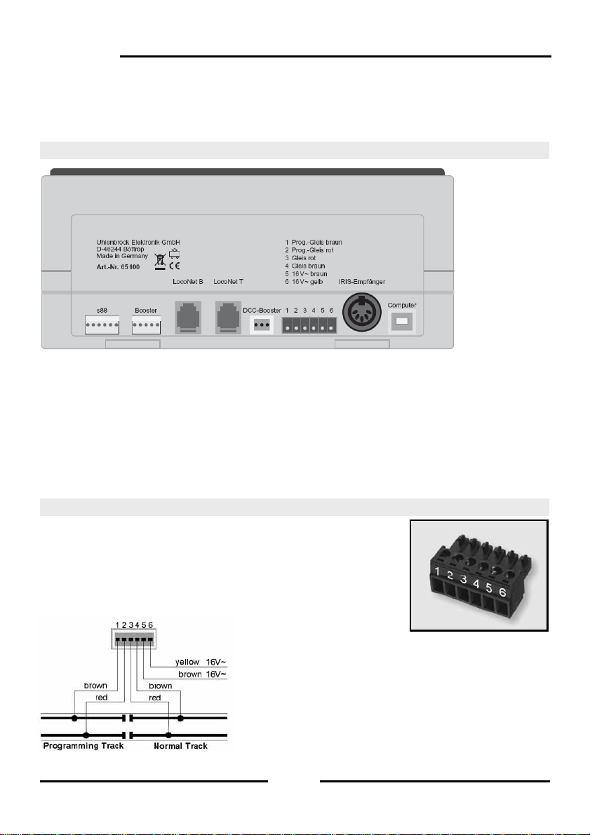
2.1 Definition of the individual Sockets
Figure 2.11 The rear view of the Intellibox II with its connections
6-way Header: s88-Feedback
5-way Header: Märklin Booster
RJ12 Socket: LocoNet B (Booster)
RJ12 Socket: LocoNet T (Throttle)
3-way Header: DCC Booster
6-way Header: Transformer, Track, Programming Track
5-way DIN Socket: additional IRIS receiver
USB Socket: USB Computer connection
2.2 Connecting Transformer, Track and Programming Track
The included 6-way plug for connecting the transformer, Track
and Programming Track is a screw terminal plug, to which the
wires are connected by tightening the screws.
The image to the right shows the assignment of the terminal s of
the plug.
The terminal assignment of the 6-way connector is
shown in the diagram on the left.
Note: For the transformer and track connection you
should use wire with as large a cross sections as
possible (at least 0.5 mm²). The connection to the track
should be made at several locations of the layout. We
recommend feed points with a separation of approx. 1m
for H0.
12
Page 13
Transformer
For trouble free operation a transformer of min. 52VA and 16V A C is required. With full
loading we recommend the Uhlenbrock transformer 20 070 with 70VA. The transformer
output potential should not exceed 18V ~.
The transformer’s AC potential is connected to terminal 5 (brown) and 6 ( yellow) of the 6way connecting plug.
Important: Incorrect connection ca n destroy the device because additional digit al devices
may cause a short circuit between the transformer output and the digital power.
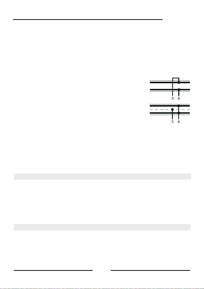
Track
2-Rail track is connected to terminals 3 and 4 of the 6-way
connecting plug.
For 3- Rail track (Märklin) the centre rail is connected to ter minal 3
(red Märklin cable) and the track body to terminal 4 (bro wn Märklin
cable) of the 6-way connecting plug.
Programming Track
The Programming track is a section of track is specially setup for programming and reading
of locomotive decoders.
This track is connected to terminal 1 (brown) and 2 (red) of the 6-way connecting plug.
Important: The track must definitely be isolated on both sides - with Märklin track it is
essential to isolate the centre rail and outer rails. During progr amming the isolation point
must not be bridged (e.g. by bogie or lighted wagon).
Note: The programming track can be used for programming and reading of decoders. It
can equally be used for normal train traffic when the Intellibox is not in programming mode.
Intellibox II
2.3 Connecting LocoNet
The Intellibox supports all devices which have a LocoNet interface.
LocoNet boosters such as Power 2, 4 and 7 are connected to LocoNet B since the digital rail
signal is available here. Connection LocoNet T is only suitable for manual control devices and
devices that do not need a digital rail signal. We recommend connecting LocoNet boosters on
large layouts to the LocoNet B socket only.
All other devices can be connected to LocoNet T.
Note: Behind a LocoNet power feed unit no track signal is available even if its input is
connected to the LocoNet B socket.
2.4 USB Computer Interface
Attention: Before the Intellibox II is connected to the PC the driver software for the
interface must be installed (see Chapter 15.3). The driver software can be found on the
included CD.
13
Page 14
Intellibox II
plug
For connecting the Intellibox to a computer you us e a USB lead with type A and B plugs,
Part No. 61070. This type of cable is also used for connecting the com puter with a USB
printer.
The Intellibox USB interface is set to a data transmission rate of 115200 Baud.
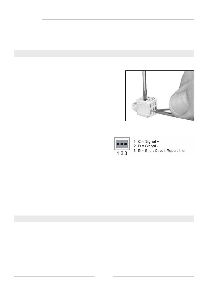
2.5 Connecting DCC Boosters
Boosters with DCC Booster interface can be connected to the DCC booster socket. Both
the DCC and the Motorola data format are output.
A 3-way clamp connector is provided for connecting
to the device. The cables of braid or wire to be
attached are stripped approx. 6 mm, carefully twisted,
and tinned if possible.
Using a narrow screw driver (2 mm) which fits in the
opening of the plug apply light pressure to open the
clamp terminal contacts. The stripped end of the
cable is inserted into the clamp terminal plug. When
pressure from the screw driver is released the cable is
fixed to that contact.
Lenz Booster
Both signal lines C and D as with the short
circuit line E are connected to the 3-way clamp
terminal plug.
Other DCC Boosters
Other DCC Boosters normally have two connecting cables which are connected to
terminals 1 and 2 of the 3-way clamp terminal plug.
Note: Because of the missing short circuit line “E“, these boosters have no way of
reporting a short circuit to the Intellibox. They are normally equipped with there own short
circuit protection.
Märklin and Arnold Digital= Boosters
Märklin Digital= Booster (6016) and Arnold Digital= Booster (86015) ar e connected with the
help of the Uhlenbrock Adapters 61 030 to the DCC Booster socket.
Figure 2.51 Attaching the cable to the clamp
Bild 2.51 Fixierung der Kabel
im Klemmstecker
Figure 2.52 Assignment of the contacts of the 3-way
connector (Cable side)
2.6 Connecting Märklin Boosters
Märklin boosters (6015/6017) and all boosters using the Motorola format that have a
Märklin booster compatible connection can be attached to the Märklin booster socket.
Connect the booster with the Märklin booster socket of the Intellibox II using the enclos ed
flat strip cable (see the booster operating instructions).
14
Page 15
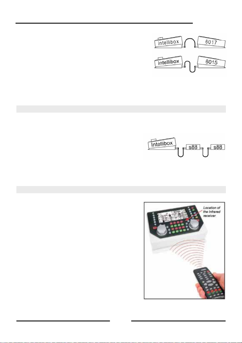
The plugs must be connected to the so that the cable on
the Intellibox and the Booster 6017 go to th e top and on
the Booster 6015 to the bottom (as shown in the
diagram).
Note: If the Booster Power 4 (Part No. 63 240) is to
transmit the Selectrix Format it must be connected to the
Intellibox Märklin Booster socket.
Tip: The Märklin Booster outputs the DCC Format when Special option 901 is set to “3“
(Setting see Chapter 4.10), otherwise the Intellibox will report the error „Short Circuit“ as
soon as the Märklin Booster is connected and the DCC Format is output.
Figure 2.61 Connection of the flat cable
Intellibox II
2.7 Connecting s88 Modules
Feedback modules serve to monitor track sections and trains in automatic operations on a
model railway layout.
All feedback modules that conform to the Märklin s88 standard c an be used on the s88
feedback input.
The flat cable supplied with the module is used to
connect the module to the Intellibox s88 input socket.
On both devices the plug must be connected so that
the flat cable goes downwards.
more modules are used the flat cable is c onnected from output of the la st module to the
If
input of the next module so that all modules are daisy chained and con nected to the s88
feedback bus (see also the manual of the particular module).
Figure 2.71 Connection of flat cables
2.8 Connecting IRIS Receivers
Receiver
The built-in receiver is located under the front panel
to the right of the [C]-key. During operation the
remote control IRIS (Part No. 66510) should always
be held in the direction of the receiver (see
illustration).
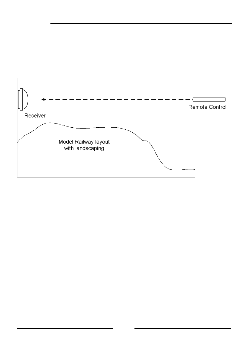
In difficult situations such as a model railway la yout in
two rooms, two further external receivers can be
used.
Auxiliary Receiver
Auxiliary receivers (Part No. 66520) are connected to
the 5-pole DIN-socket, designated “IRIS receiver“. A
single auxiliary receiver can be connected directly.
When two auxiliary receivers are used they are
connected to the Intellibox via a Y-cable.
15
Page 16
Intellibox II
The receiver is attached to the back wall of the model railway layout using the provided
double sided adhesive pad. As shown in the sketch, the are a bet ween the receiver an d the
transmitter must be free from obstacles. For trouble-free operation, the receiver must
always “see” the transmitter so that trouble free operation is possible. The most sensitive
direction of the receiver is perpendicular to the center of the cov er dome to the rear wall of
the receiver.
During operations the remote control should be always held toward a receiver. A red
control LED under the transparent dome of the receiver blinks when the receiver has
received the infrared signal from a remote control.
16
Page 17
3. The Operating Elements
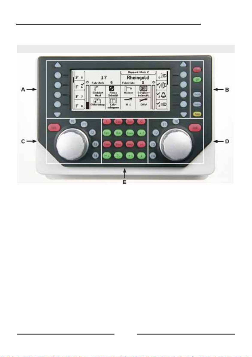
3.1 Overview of the Operating Elements
Intellibox II
A. Backlit LCD with associated display keys with information about locom otive address or
name, speed and driving direction and the current operati ng mode, e.g. in control desk
mode shows turnout or signal status. The display ke ys are for selecting entries from the
lists which are shown down the side of the display, e.g. in the control desk mode the list
of special functions
B. Key area with operational status indicator, main control keys and help function
C. Left Controller with function keys and locomotive selection key
D. Right Controller with function keys and locomotive selection key
E. Key block with telep hone keyboard and special keys
stop/go
Operating status and key for interrupting and restarting of running operations
mode
Selection of the operating mode e.g. operating desk mode, feedback mode, route mode,
LISSY mode, programming mode, etc.
menu
Setting options related to the current operating mode and return to the operating desk
mode from each submenu
help
Help for every operating situation
17
Page 18
Intellibox II
Left Controller
With endless rotary control, direction switch, f0 for switching light function , 4 function keys
and locomotive selection key.
Right Controller
With endless rotary control, direction switch, f0 for switching light function , 4 function keys
and locomotive selection key.
Centre Key block
Telephone key pad for entering digits and characters. With special keys for easy entry of
addresses and working in the individual modes.
LCD Display
The large backlit LCD Display provides information about both currently controlled
vehicles, currently selected operating mode (e.g. in control desk mode, display of turnout
or signal status) and the assignment of the display keys, which always match the in dividu al
operating situations.
Display keys
For selecting entries from the lists which are shown down the side of the displa y, e.g. in the
control desk operation the list of the spec ial functions or the selection of individual menu
items.
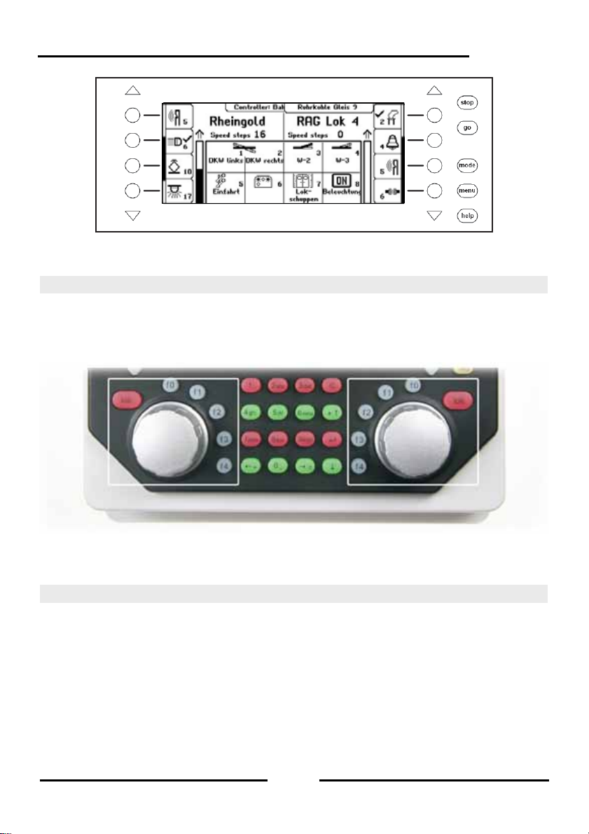
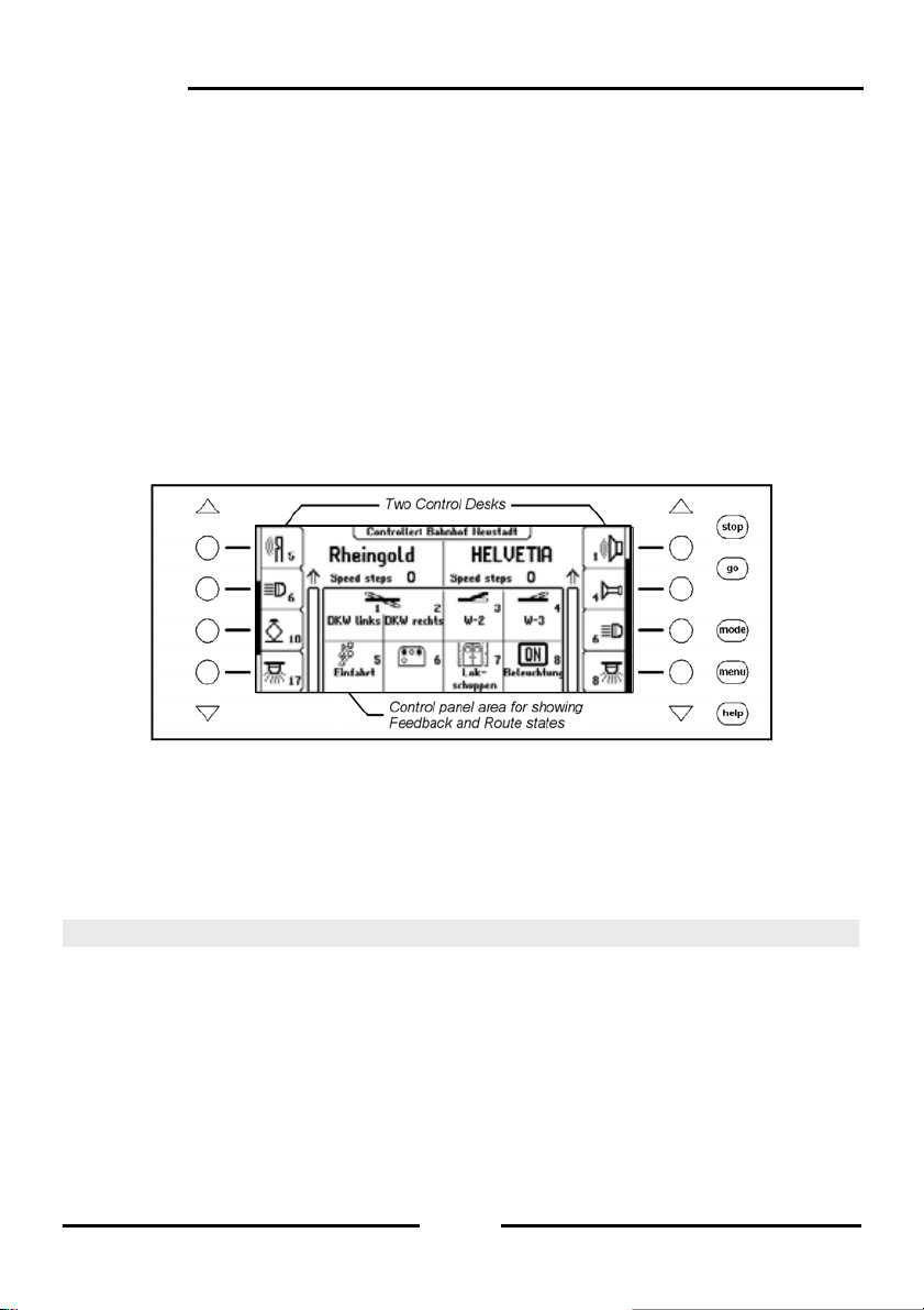
3.2 The Display with the Display keys
The large backlit LCD Display is clearly arranged on the panel. The three part display
provides a clear overview of the current running status at all times.
The top area shows the current selected vehicle for each of the controllers along with their
speed and driving direction.
The special functions are switched by the round display keys beside the display. If the
controlled locomotive has more than 4 special functions, then the scrollbar in dicates the
active items in the list. The triangular keys (= Scroll k e ys) can p age thro ugh this list up ward
or downward. Their background light indicates the possible direction.
If the LISSY system is connected to the Intellibox the messages indicating the current state
of the locomotive is shown above the locomotive name. This information is stor ed in the
Intellibox and displayed again when the locomotive is next called. The display is updated
whenever the locomotive passes another place on the layout that is being monitored by the
LISSY system.
18
Page 19
The middle has information about the current operating mode, e.g. in the control desk
mode the state of turnouts or signals.
Intellibox II
3.3 The Controller
Locomotives can be called and controlled by the control desk. The Intellibox has two
independent integrated controllers. They are on the left and right side of the unit.
Digital decoders with different data formats can be controlled simultaneously.
The controllers are also operational during programming or while changing presets.
Each control desk consists of the throttle control knob for changing locomotive speed and
driving direction as well as of the f0 to f4 special function keys. The [lok]-key on each
control desk serves to select new locomotives on the controller.
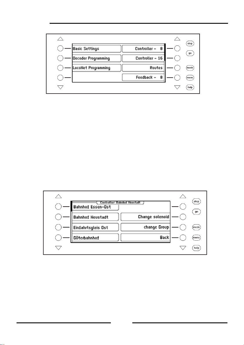
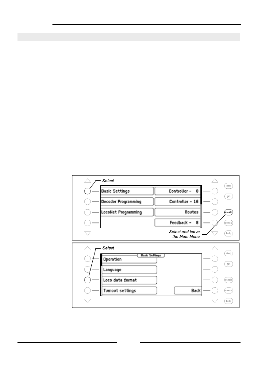
3.4 Menu Operation
The Intellibox is operated by three main control keys [mode], [menu] and [help]. [Mode]-key
switches between the device modes. If it is pressed the main selection menu appears a nd
shows all the modes. On the left side are the modes that fully utilize the displ ay and on the
right are the modes which represent the control desk in the display in combination with
other control elements (control desk, routes, etc.) in the middle display area.
19
Page 20
Intellibox II
The [Menu]-key leads to selection or configuration menus, which belong to each device
mode. In the control desk mode e.g. a new control desk is selecte d or a solenoid is linked
with a name and a symbol. A further press of the [menu]-key returns back to the Co ntrol
Desk.
The [help]-key can be call context sensitive help at any time.
The individual menus are always navigated with the display ke ys besid e the left and on th e
right the display. Depending upon the operation the dis play gives the meaning of these
keys. If more than four options are available the triangul ar scroll keys light up. A scrollbar
indicates if different options are still present above or below the four represented. These
other options can be accessed with the triangular scroll keys.
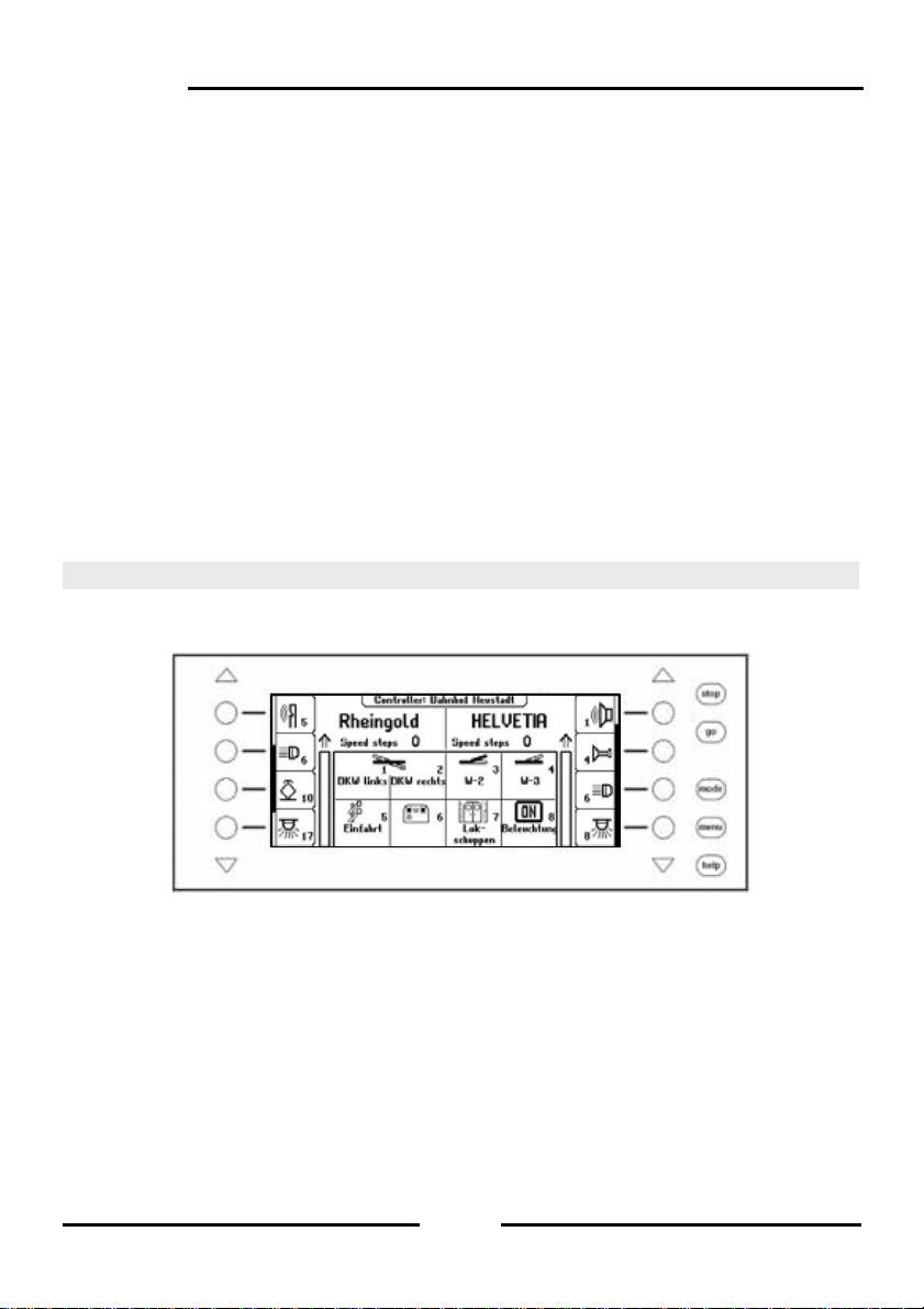
The menus are constructed in such a way that the left side has the main options. T he right
side shows associated control steps or a submenu which belong to one of the options on
the left side. Here one often also finds the “Back” key to exit the menu or with which to
return to a parent menu. For example the control desk menu:
20
Page 21
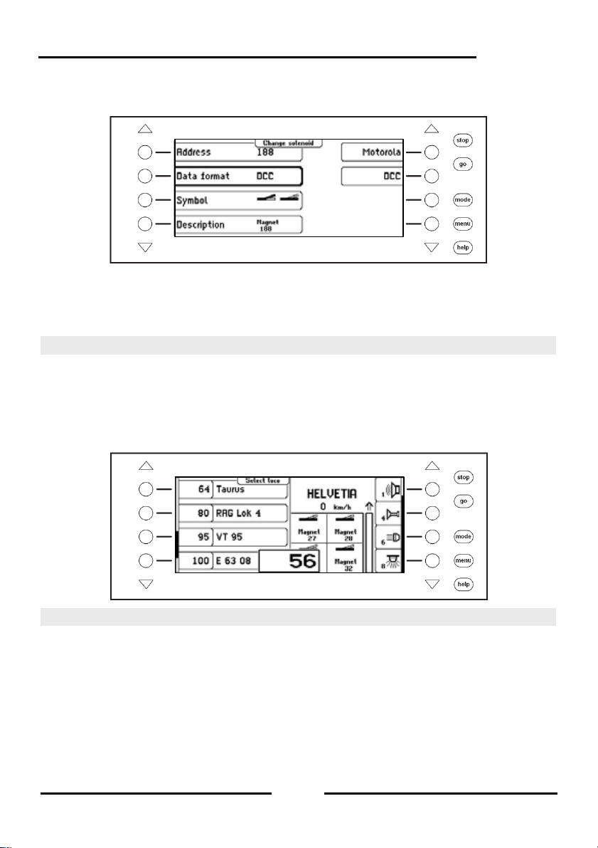
If an option on the left side is activated by key press, this is repres ented by a frame around
the menu element, e.g.:
The right side now shows options for this point. In this example the data format for
solenoids can be set. The submenu is faded out again by another operation of the left
selection key. If a selection key on the right is pressed the selection for this parameter
(here the data format) is accepted and indicated left.
Intellibox II
3.5 Entry of Numerals
If during the course of operating the device input of a number of s equences is required to
enter a locomotive or a solenoid address it is done with the alphanumeric ke yboard in the
centre of the unit (key block). As soon as a digit key is pressed an input field appears. The
input can be completed in the field and confirmed with []-key. The last entered digit can be
deleted with the [C]-key. The [+]-key increments the number in the input field by one,
while []-key decrements the number by one.
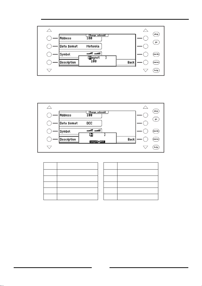
3.6 Entry of Names
While operating the device input of names may be necessarily to provide a locomotive or a
turnout with a name. This input can be done with the alphanumeric keyboard in the centre
of the unit (key block). As soon as a change of name is selected, depending upon context,
a one or two line input field appears.
The actual line in which the text can be entered is marked by square brackets. The Curser
position at which next character will be changed is s hown inverted. The arrow keys [] and
[] can move the cursor within the line. The arrow keys [] and [] can be changed
between the lines. The [C]-key will delete the character at the input position.
The character input is ended with the []-key.
21
Page 22
Intellibox II
pq
g
When an alphanumeric key is pressed a list of characters which can be inserted appears.
As is the case for mobile phones repeated pressing of the key selects characters from this
list. If the key is then released for a short time or if another key is pr essed the character at
the cursor position is used.
Here are the symbols assigned to the alphanumeric keys 0-9:
Key Assignment Key Assignment
1 -1.,()<>_:+*/#! 6 mno6MNOöÖ
2 abc2ABCäÄ 7
3 def3DEF 8 tuv8TUVüÜ
4
hi4GHI 9 wxyz9WXYZ
5 jkl5JKL 0 (space)0
Note: Key [0] will overwrite the existing character at the cursor positi on either with a blank
or the number “0” inserted.
rs7PQRSß
22
Page 23

Intellibox II
4. Basic Settings Menu
The Basic Setting of the Intellibox II can be changed by menu driven options and are the n
saved to non-volatile memory.
The Basic Settings Menu is reached by pressing the [mode]-key and selecting “Basic
Settings” submenu.
The Basic Settings Menu has the following items:
• Operation
• Language
• Loco data format
• Turnout setting
To leave the main menu press the [mode]-key.
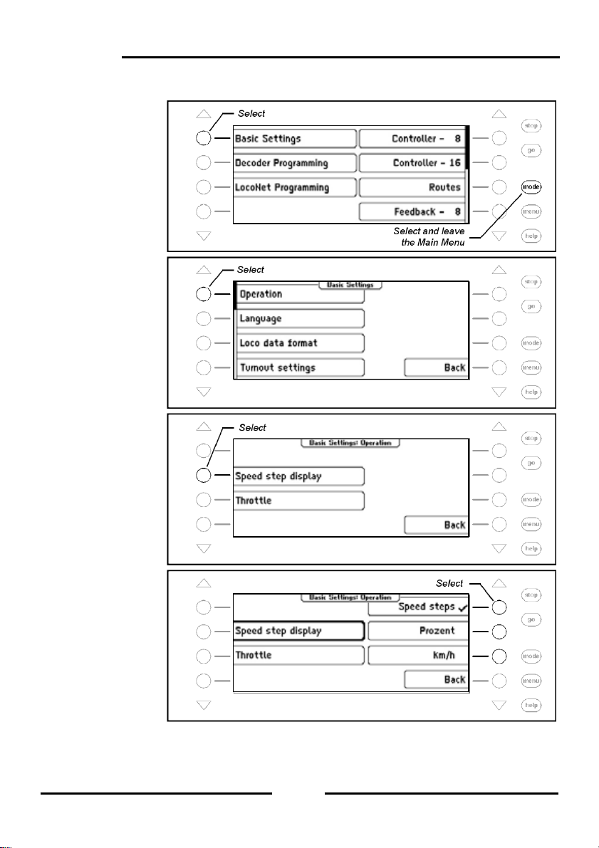
4.1 Menu Item Operation
4.1.1 Speed Display
The display of the vehicle speed can be in one of three ways.
Speed Step display
The display is directly in speed steps according to the decoder data format 0-14, 0-28, 0-31
or 0-126 speed steps.
Percent Display
The display is in percent of the maximum speed irrespective of the data format being used.
Display in km/h
If the individual locomotive address in the database has a top s peed assigned to it (see
Chapter 5.6.5) the speed can be calculated and displayed in km/h.
The display is preset to “Speed Step display”.
• Hand Control
• Display
• Programming track
• Interface
• s88-Settings
• Special options
• Software Version
• Start mode
• Database
• Feedback
23
Page 24
Intellibox II
Procedure:
Step 1
Step 2
Step 3
Step 4
24
Page 25
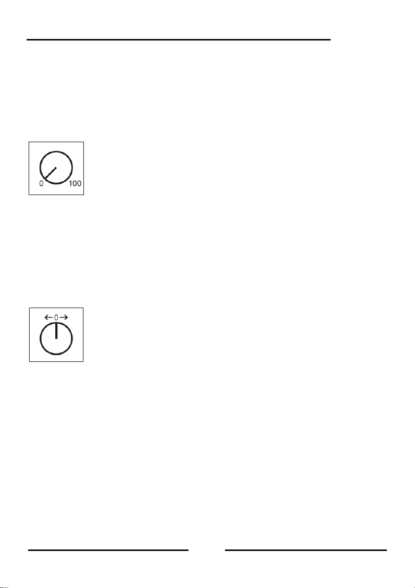
4.1.2 Throttle
The throttle controls on the Intellibox II can be selected to operate like a DC throttle or an
AC throttle.
The factory default setting is “AC throttle”.
AC Throttle Mode
The AC Throttle Mode is set up to control locomotives like the AC transformers in 3-r ail
systems.
Figure 4.1.2.1 Principle of an AC throttle
In this operating mode the speed increases by turning the knob to the ri ght and decreases
by turning the knob to the left. When either the maximum speed or the zero speed is
reached further rotation in the same direction of the knob has no effect. In this operating
mode the direction is switched with a light pressure on the throttle knob.
If the reversing switch is activated while the vehicle is running the vehicle will firstly stop
and only then switch the direction over. It depends on the decoder data format if this
causes an emergency (Motorola, DCC) or stops using the setup deceleration (Selectrix).
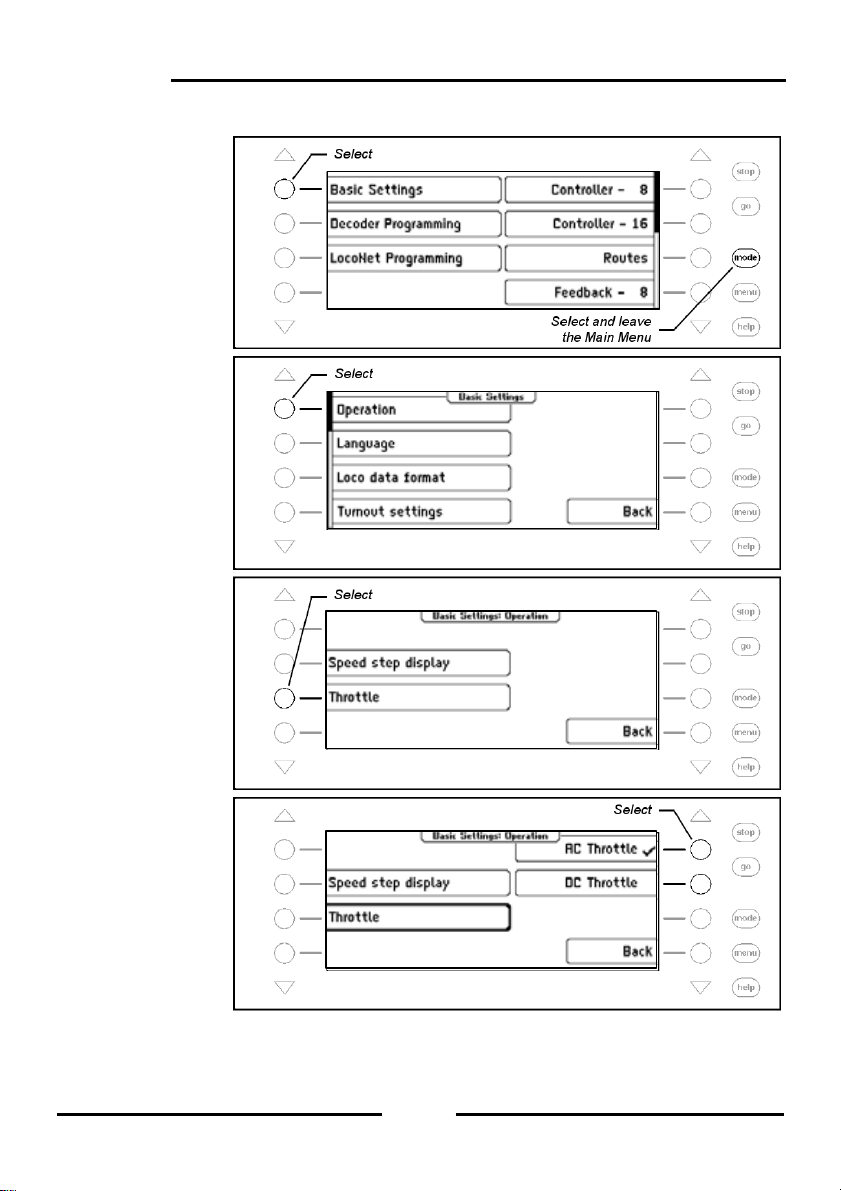
DC Throttle Mode
The DC Throttle Mode controls the locomotives as is common in the 2-rail DC systems.
Intellibox II
Figure 4.1.2.2 Pr inciple of a DC throttle
In DC operating mode a right turn of the control knob, starting from speed step zer o, the
locomotive will move in a direction. When the control is turned back the speed is re duced
until the loco stops. A further turn to the left will cause the locomotive to accelerate in the
opposite direction.
If the maximum speed of the loco is reach further turns in that direction has no effect. In
this operating mode a light pressure on the control k nob will cause the vehicle to stop. It
depends on the decoder data format if this causes an emer gency ( DCC) o r stops using t he
setup deceleration (Motorola, Selectrix).
25
Page 26
Intellibox II
Procedure:
Step 1
Step 2
Step 3
Step 4
26
Page 27
Intellibox II
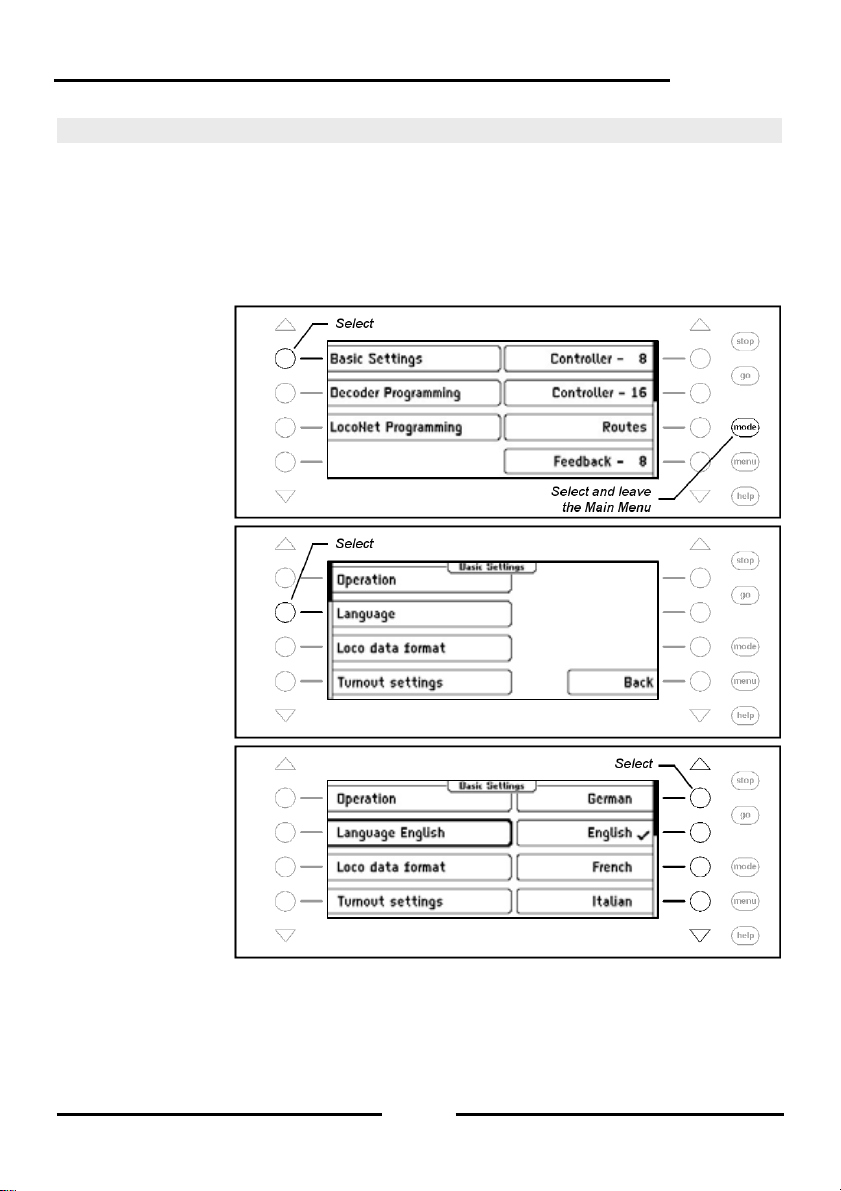
4.2 “Language” Submenu
For the language of the text on the display the following languages can be selected:
• German
• English
• French
The preset is “German“.
Procedure:
Step 1
Step 2
Step 3
• Italian
• Dutch
• Swedish
• Spanish
• Portuguese
• Danish
27
Page 28
Intellibox II
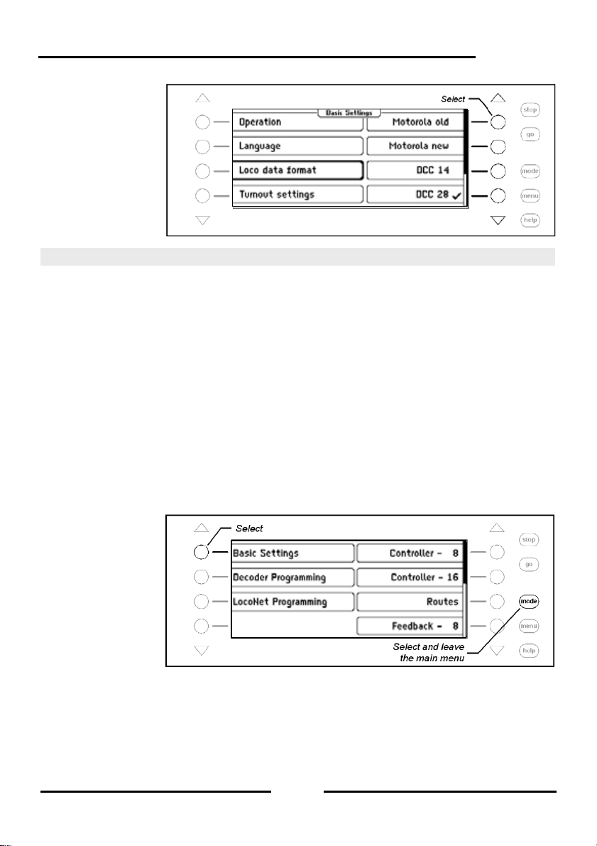
4.3 ”Locomotive Data Format” Menu
Sets the locomotive data format that will be used for decoder the first time they are called
up and when an individual data format is not assigned to it.
The data format you will use most should be set up here before the first time you use the
Intellibox II. The preset value is the new Motorola data format.
Possible settings are:
Motorola - old
old Motorola Data format
Locomotive decoder with 14 speed steps, without special functions
Function decoder controls with special functions keys f1 to f4
Motorola - new
also Spur-I-Format with 14 speed steps, with locomotive special functions f1 to f4
DCC 14-28-128
DCC Format with 14, 28 or 128 speed steps, up to 32767 special functions
Selectrix
Trix Selectrix with 31 speed steps and 4 special functions
Note: The format of individual decoders can eas ily be change d at any time indep endent of
the locomotive data format in the “Change Loco Data” Option.
Procedure:
Step 1
Step 2
28
Page 29
Step 3
Intellibox II
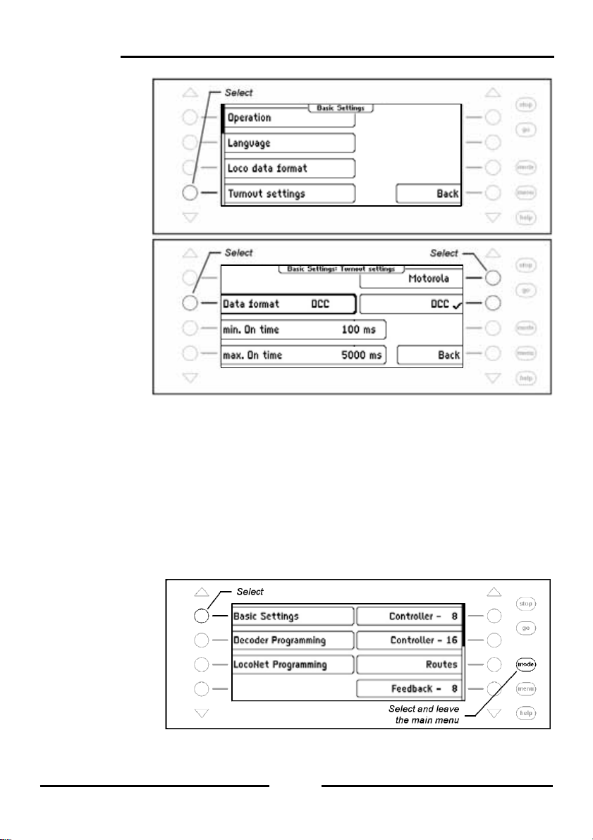
4.4 “Turnout settings” Menu
Attention: Turnout decoders from Märklin and Viessmann for the Motorola data format
each control four turnouts. The address selected by the DIP switch on the decod er is not
identical to the turnout addresses of the turnouts connected to the decoder.
All setting menus in the Intellibox II use turnout addresses and not turnout decoder
addresses.
The appendix has a Table showing the relationship of the DIP switch position and the
turnout addresses and also the assignment of the Märklin Keyboards.
4.4.1 General Data format
Sets the turnout data format that will be used for decoders the first time they are called up
and when an individual data format is not assigned to them as outlined in Chapter 6.7.
The data format you will use most should be set up here before the first time you use the
Intellibox II.
The preset value is the Motorola Data format.
Procedure:
Step 1
29
Page 30
Intellibox II
Step 2
Step 3
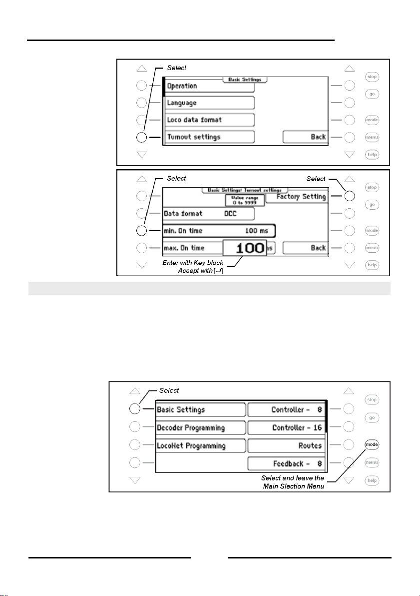
4.4.2 Switching Times
The switching pulse that is generated when a control key is pressed norm ally lasts as l ong
as the key is held. To ensure that the switching function s till works with a very short key
press and the solenoid is not damaged by a long activation the Intellibox II has a minimum
and maximum switching time. The factory defaults for the switching time is 100 ms (0.1
sec.) minimum time and 5000 ms (5 sec.) for the maximum time.
Valid vales are between 0 and 9999 ms.
Note: In DCC decoders the switching times can only be set for turnout decoders that are
not configured for “continuous” operation.
Procedure:
Step 1
30
Page 31
Step 2
Step 3
Intellibox II
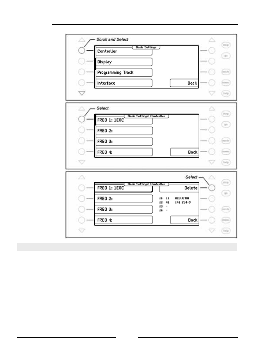
4.5 “Hand Controller” Menu
When an Uhlenbrock FRED hand controller is connected to Intellibox Loc oNet for the first
time, the center will automatically assign an internal Identification number (ID) to the
FRED. The center can forward locomotive addresses to the FRED under this hand
controller number.
The Hand controller Menu can be used to display the assignment of the FRED number and
matching ID and individual FREDs can be deleted.
Procedure:
Step 1
31
Page 32
Intellibox II
Step 2
Step 3
Step 4
4.6 “Display” Menu
The Display Menu is used to set the brightness and Contrast of the display.
Procedure:
32
Page 33

Step 1
Step 2
Step 3
Intellibox II
Step 4
33
Page 34

Intellibox II
4.7 “Programming Track” Menu
It is possible to select whether the connections for the programmi ng track provides only
programming power or if the output automatically switches between normal digital po wer
and programming power.
Only Programming Track
There is no power on the programming track output, it is only fed with programming power
during read and write operations.
Automatic
During normal running the programming track output provides normal digital po wer. It is
automatically switched over to programming track power as soon as the Programming
Menu is selected. That way a model railway layout can setup a siding to be the
programming track and also a normal siding.
Very important: The track segment must be isolated on both sides. It must not have an y
electrical connection with the rest of the layout and must be exclusively provided with
power from the programming track output. The isolations must not be bridged by a vehic le
during programming operations (bogie, lit wagon).
The preset value for the programming track is “automatic”.
Procedure:
Step 1
Step 2
34
Page 35

Intellibox II
4.8 “Interface” Menu
This menu is used to change the baud rate of the Intellibox II. The preset value is 115200
bit/s.
Procedure:
Step 1
Step 2
4.9 “s88 Setting” Menu
Unlike in other digital centers the Intellibox II stores the feedback signals.
To process this polling as fast as possible the Intellibox II needs to know how many s88
feedback modules are connected to the s88 feedback bus.
Using a Start address the s88 feedback modules are configured to use these feedback
addresses in ascending order.
35
Page 36

Intellibox II
Procedure:
Step 1
Step 2
Step 3
Step 4
36
Page 37

Intellibox II
4.10 “Special Options” Menu
The Intellibox II has various special options which affect the operation of the devic e and
can differ between software versions. Each special option can be selected with an
identification number. The individual special options can be obta ined in a separate list for
the particular software. With later software changes a file containing the relevant
explanation is included in the update package.
Procedure:
Step 1
Step 2
Step 3
37
Page 38

Intellibox II
Step 4
The right display keys can be used to set special option bits to 1 or 0.
4.11 “Software-Version” Menu
Use this Menu item to find the serial number of your device and the Version number of the
System software.
Procedure:
Step 1
Step 2
4.12 “Start Mode” Menu
When the playing is finished the Intellibox II saves all the data. The Start Mode Menu can
be used to configure which of the data will be restored at the next start.
no Loco data
No data from the previous play session is to be restored.
38
Page 39
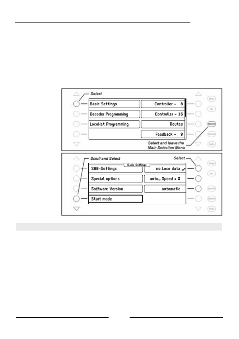
auto, Speed = 0
All data from the last operation about locomotives and Multi-traction with their direction and
the state of their special functions are recovered from the last use.
automatic
In addition to the data about direction and special function s the speed of all locomotives is
restored. That way the entire operation continues on from when it was last switched off.
Note: A safety question appears if all locomotives are definitely to run at their old speed.
Procedure:
Step 1
Step 2
Intellibox II
4.13 “Database” Menu
The Intellibox has a database in which all user settings for locomotiv es, turnouts, feedback
units, Routes, LISSY receivers and booster are saved. The assigned names and symbols
for the individual elements are saved. Two memory buffers are available for the active
database and for a copy
The “Database” Menu has the following options:
Make Copy
A copy of the active database is made into the copy buffer.
Swap with Copy
The data is swapped between the active database and the cop y buffer. The data from the
copy buffer are put into the active data buffer and active data buffer is placed into the co py
buffer.
.
39
Page 40

Intellibox II
Delete
The active data buffer is flushed. Subsequently all names are rep laced with the relevant
addresses and basic symbols are used for functions, turnouts and feedbacks.
Demo Database
A Demo database with preset values of names and symbols is loaded.
Procedure:
Step 1
Step 2
Step 3
40
Page 41

Step 4
Intellibox II
4.14 “Reset” Menu
This submenu is used to reset the Intellibox II back to factory defaults.
Intellibox
The entire device does a reset and start afresh like when the operating power is turned on.
Configuration
All changes under Basic Settings are erased. All changes to speci al option are reversed.
The selected language remains.
Locomotive Data format
The entries made for individual locomotive decoder in “Change Loco Data” submenu
(Chapter 5.6.5), are erased. The general data format for locomotive decoders (Chapter
4.3) is selected for the respective decoder addresses.
Turnout Data format
The entries for the individual turnout decoders made in submenus “Name, Symbol and
Data format of solenoid settings” (Chapter 6.7) are erased. The general data format for
turnout decoders is used for the respective decoder addresses.
Procedure:
Step 1
41
Page 42

Intellibox II
Step 2
Step 3
Step 4
42
Page 43
Intellibox II
5. The Control Desk
Locomotives can be called up and controlled with a control desk. The Intellibox has two
built-in, independent from one-another control desks. They are located on the left and rig ht
side of the device control panel.
Digital decoders with different data formats can be controlled simultaneously.
The Control desks are also operational during programming and while changes are made
to the presets.
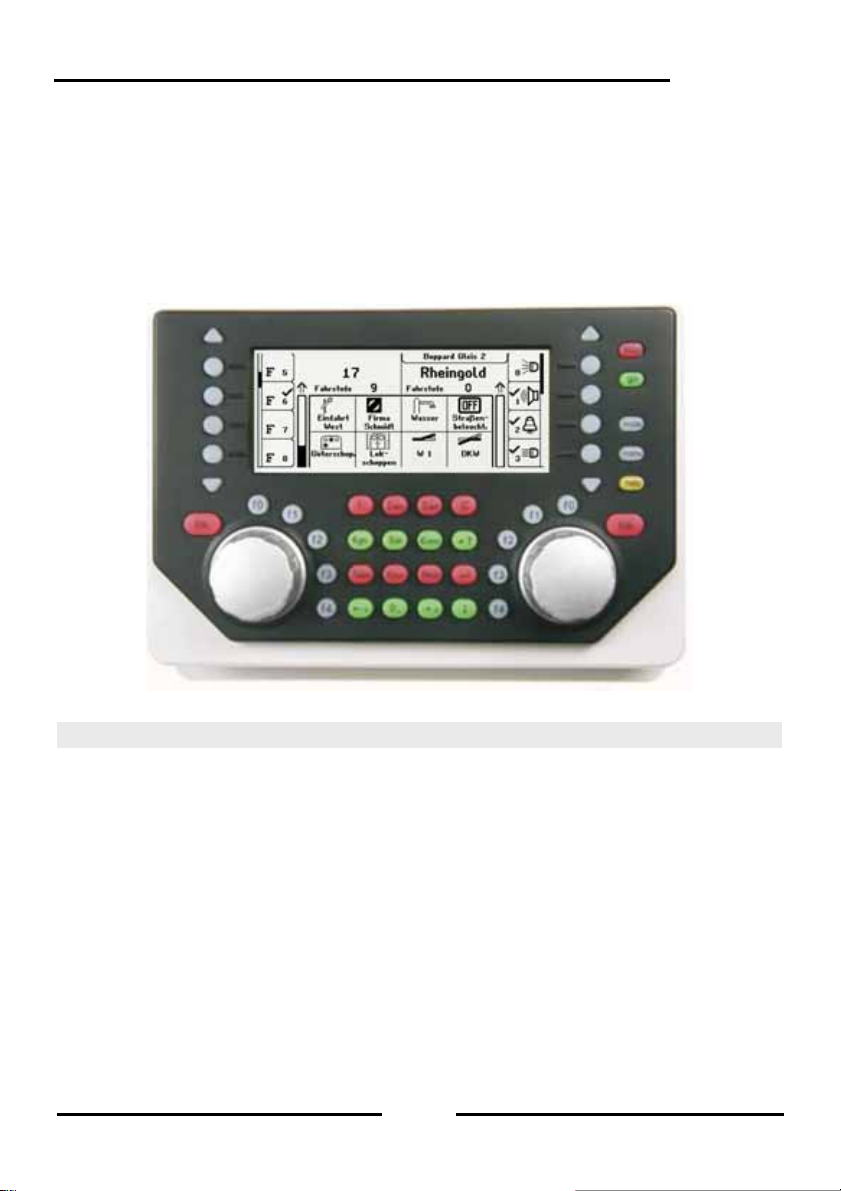
Figure 5.11 The Front view of the Intellibox
5.1 Operating Elements
Each control panel has the following elements:
The [stop]-key
The [stop]-key turns the power off to the main line and the track sections powered by
connected boosters. The “STOP – no track power” message is then shown in the display.
This key is used by both control desks.
The [go]-key
The [go]-key turns the power on to the main line and the track sections are p owered by
connected boosters. It is used by both control desks.
Note: If during normal running the [go]-key is pressed and held, the [stop]-key is also
pressed or when the power is off (red LED beside the [stop]-key is lit) the [stop]-key is
pressed and held, and the [go]-key is also pressed the Intellibox II switches to the Halt
Mode. During the Halt Mode all locomotives are stopped, the track power remai ns on so
turnouts and signals can still be switched. After pressing the [go]-key all locomotives r un
with their previous speed.
43
Page 44
Intellibox II
The keys [f0] [f1] [f2] [f3] [f4]
These keys switch locomotive special functions such as Light, Special lighting, Horn or
Smoke unit.
The [lok]-key
starts the selection of the wanted locomotive for respective control desk.
If a vehicle is already selected then pressin g the [lok]-key twice will enter the Loc o Menu.
Here you can build a Multi-traction, assign locomotive to a hand controller or edit
locomotive data.
The Throttle knob
The throttle knob is used to change the locomotive speed and direction. The rotating
throttle without end stop on the Intellibox II automatically restores the saved speed when a
new locomotive is selected.
The Display
The large backlit LCD display always gives you an exact overview of the running status.
The display of the used locomotive, running speed and direction of actually controlled
vehicles are shown separately for each controller. The display keys at the sides are
assigned with loco special functions. If the controlled locomotive has more than 4 special
functions the triangular scroll keys, top and bottom can be used scroll through further
functions. If it is possible to scroll up or down the corresponding scroll key is lit up.
The scrollbar diagrammatically shows at which point in the selection ran ge the displ a y keys
are.
5.2 Locomotive Addresses und Names
In a digital control system an individual locomotive is selected by an address. This is a
sequence of digit, which are installed in the individual locomotive decoder for identification.
Each decoder is set to its own address so that the locomotive can be addressed by this
particular address.
In order to simplify locomotive selection each locomotive can be assig ned a name. If the
assignment is done once the Intellibox II saves it permanently.
In every new locomotive selection it can be selected from a list by name.
44
Page 45

5.2.1 Locomotive selection
If a vehicle is to be controlled with the Intellibox II it must be called under the decoder
address or under the assigned name.
Locomotive selection is started by pressing the [lok]-key. The display shows a list of
locomotive addresses and names. The desired locomotiv e is selected with the selection
keys. If more then 4 locomotives are available the scrollbar appears and the triangular
scroll keys can be used to scroll through the list. The [mode]-ke y can be used to switch
between sorting by locomotive address or by name.
If the locomotive is not on the list its address can be entered numerically. After pressing the
digit an input field appears to verify the digit inputs. The [C]-key can be used to delete the
last digit and the [ ]-key to confirm the entry.
Note: If the loco being called up is already being c ontrolled by another throttle control the
Intellibox II will inform you with message: “The selected loco is already under co ntrol!”. Th e
vehicle can then be controlled with both throttles.
Intellibox II
5.3 Throttle
The throttle is for changing the speed of the locomotive and its direction. The rotary control
without endpoints automatically restores the save speed of a newly selected locomotive.
The throttle has two operating modes:
AC Throttle Mode
The AC Throttle Mode is set up to control locomotives like the AC transformers in 3-r ail
systems.
In this operating mode the speed increase b y turning the knob to the right and decreas es
by turning the knob to the left.
When either the maximum speed or the zero spe ed is reached further r otation in the same
direction of the knob has no effect. The maximum speed or zero speed then remains.
The direction is changed by lightly pressing on the control.
Figure 5.31 Principle of an AC throttle
45
Page 46

Intellibox II
If the reversing switch is activated while the vehicle is running the vehicle will firstly stop
and only then switch the direction over. It depends on the decoder data format if this
causes an emergency (Motorola, DCC) or stops using the setup deceleration (Selectrix).
DC Throttle Mode
The DC Throttle Mode controls the locomotives as is common in the 2-rail DC systems.
In DC operating mode a right turn of the control knob, starting from speed step zer o, will
move the locomotive in a direction. When the control is turned back the speed is reduc ed
until the loco stops. A further turn to the left will cause the locomotive to accelerate in the
opposite direction.
If the maximum speed of the loco is reached further turns in that direction has no effect.
In this operating mode a light pressure on the control knob will cause the vehicle to stop. It
depends on the decoder data format if this causes an emer gency ( DCC) o r stops using t he
setup deceleration (Motorola, Selectrix).
Preset
In factory default setting the AC Throttle Mode is active. This can be changed in the
Intellibox Basic Settings Menu (See Chapter 4.1).
Figure 5.32 Principle of a DC throttle
5.4 Light and Special functions
The function keys beside the throttle control knob can be used to switch the light and
special functions f0 to f4 of locomotive and function decoders.
The special functions f0 to f28 (DCC) for a locomotive are shown in the display and can be
switched with the selection keys. Active functions are indicated by a tick. If more than 4
functions are available, the triangular scroll keys can be used to scroll through the list.
46
Page 47

Intellibox II
5.5 The LokPosi Display
The LokPosi Display in conjunction with the LISSY System shows the position of a loco.
The Intellibox II gets information from the LISSY System about which locomotive is at
which position on the layout. This information about the location of a locomotive is saved
by the Intellibox II. If a locomotive is called up its location is displayed in the LokPosi field.
If the loco moves the indication is deleted because the locomotive has departed the last
location. If the loco enters another track section that is controlled by a LISSY receiver the
new location is displayed in the LokPosi field.
The LokPosi field either contains the number of the LISSY receiver, at which the loco is
located or the name of that track section in the event that the LISSY receiver has been
assigned a name. How a name can be assigned to a LISSY receiver is outlined in Chapter
9.6.
47
Page 48

Intellibox II
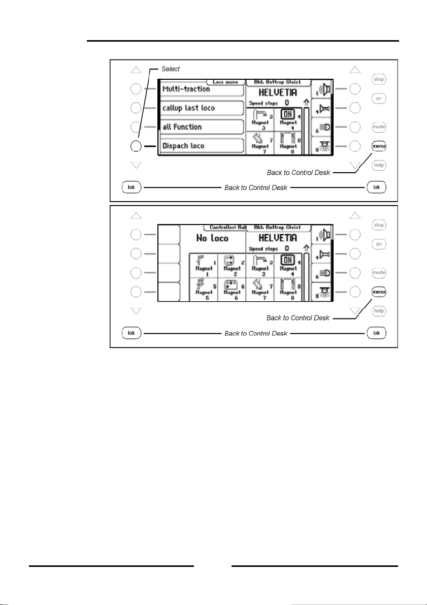
5.6 The Loco Menu
The key sequence [lok] and [menu] or 2x [lok] calls up the Loco Menu for the currently
controlled locomotive. Here you can reach following functions:
• Multi-traction
• Call up last locomotive
• Switch all functions
• Dispatch locomotives
• Edit locomotive data
• FRED assignment
5.6.1 Multi-traction
The Intellibox II can control up to 4 locomotives together with the one controller. A
locomotive can be added to a Multi-traction either by its decoder address or its name. A
total of up to eight different Multi-traction are possible.
Building a Multi-traction
Note: The combination of [lok] and [+] keys goes directly into Multi-traction Menu for
adding and removing locos.
Step 1
48
Page 49

Step 2
Step 3
Step 4
Intellibox II
49
Page 50

Intellibox II
Step 5
Deleting a Multi-traction
Step 1
Step 2
50
Page 51

Step 3
Step 4
Behaviour of Multi-traction Locomotives
A Multi-traction can only be called up under the address or name of the “base locomotive”.
If a traction locomotive is called under its own address Multi-traction appears in the display
in place of the speed indication, but no direct ion indic ation. The direction of this locom otive
can however be changed so that at the start of the Mu lti-traction operation al l vehicles can
run in the same direction.
Note: The direction can only be change if the entire Multi-traction is stationery. The speed
step must be set to “0” under the address of the base locomotive.
The special functions of a coupled loco in a Multi-traction can be individually controlled
under its own address and independent of the base locomotive.
If locomotives having decoders with different number of speed ste ps are coupled into a
Multi-traction the group is controlled according to the locomotive with the lowest number of
speed steps. If for example a decoder with 28 speed steps is coupled with a decoder with
14 speed steps, the decoder with 28 speed steps will change its speed with every notch of
the throttle, but the one with 14 speed steps only with every second notch. It therefore
makes sense to use the locomotive with the least number of speed steps as the base
locomotive.
Intellibox II
51
Page 52

Intellibox II
Important: For troubl e free operation of multiple locomotiv es in a Multi-traction it must be
ensured that coupled locomotives have the same minimum and maximum speed.
Note: The setting of the minimum and maximum speeds must be programmed into the
locomotive with the appropriate parameters. Details for this are in the particular decoder
manual.
5.6.2 Last called up Locomotive
The Intellibox II notes the last 4 locomotives called up by a control desk. The 4 locom otiv es
can be quickly recalled via the Loco Menu.
Procedure:
Step 1
Step 2
52
Page 53

Step 3
5.6.3 Controlling All Functions
The Intellibox II can control function decoders which can be switched with a function
address up to 32767. Directly accessible from the loco control panel ar e special function
light (f0) and special functions f1 to f28. These special functions can be switched with
symbols and by the keys beside the display. T o switch the higher functions (>28) the Loc o
Menu must be used. Special functions from f0 to f32767 which are accessible via a
locomotive address can be switched from the submenu “All Functions”
Procedure:
Step 1
.
Intellibox II
53
Page 54

Intellibox II
Step 2
Step 3
Step 4
54
Page 55

Step 5
Intellibox II
While the “All Functions” Menu is open the loc omotive can be controlled by the controller
as normal. The locomotive speed and direction are shown in the display.
5.6.4 Dispatching Locomotives
If a vehicle that is being controlled by an Intellibox II controll er is to be taken over by a
controller which does not have the capability of entering the locomotive address (e.g.
FRED hand controller from Uhlenbrock, BT-2 hand controll er from Digitrax) the locomotive
address must be placed into the dispatch buffer. After that the Hand cont rollers without an
address input can take over the address. The manual for the particular Hand controller will
describe the key combination is used to take over the address from the Intellibox II, after it
has been “dispatched”.
Procedure:
Step 1
55
Page 56
Intellibox II
Step 2
Step 3
The locomotive (here the “Rheingold”) is no w in the dispatch buffer and can be taken b y a
Hand Controller.
Note: The key sequence [lok] – [C] – [lok] likewise dispatches a locomotive (no Multitraction locomotives).
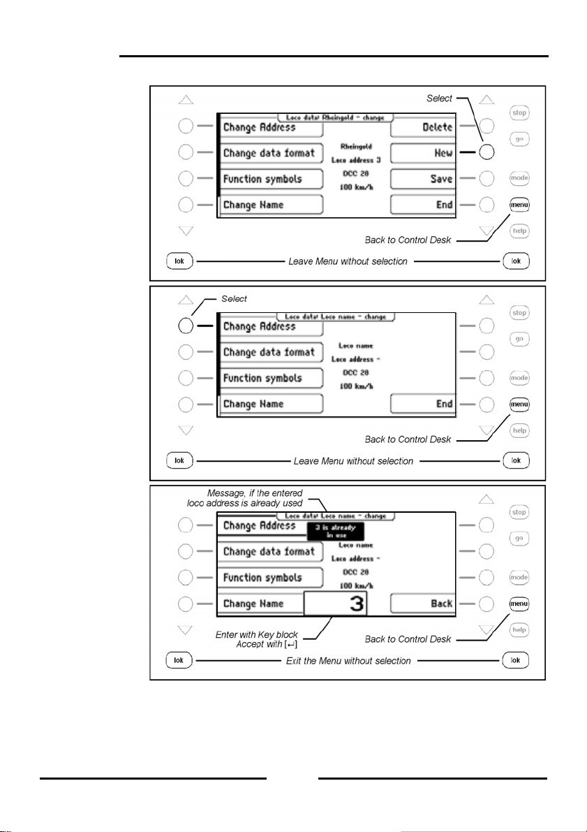
5.6.5 Edit a Loco dataset
Every locomotive in the Intellibox II has an associated dataset. This can have the foll owing
entries:
Change Address
Should a vehicle receive a new address with a new deco der it is simp le th e quickly change
the address without having to discard the dataset or enter a new one.
Set Data format
Every new decoder is firstly addressed by the general dat a format selected in the Basic
Settings (Setting see Chapter 4.3). If desired however each locomotive address can be
assigned its individual data format.
56
Page 57

Assign Symbols to Functions
The list of special functions in the display can have a maximum of 28 entries (for som e
DCC decoders). The standard indication “F” for function can be replaced b y a symbol that
represents the particular function for a better oversight. For non-assigned special functions
the display can be hidden.
Assign a Name
A name can be assigned to every locomotive address. As soon as a name is assigned for
a locomotive it is shown in the display in place of the address. Both the name and the
address are used in the Loco selection menu for the throttle controls.
Define Maximum Speed
To display a vehicle speed in km/h at the top speed of the individual locomotive ad dresses
must be entered in the Locomotive database.
The top speed is shown when a locomotive runs at the top speed step.
The speed display of the intermediate speed steps are calculated in proportion.
Procedure:
Enter a new Loco dataset
Step 1
Step 2
Intellibox II
57
Page 58
Intellibox II
Step 3
Step 4
Step 5
58
Page 59

Step 6
Step 7
Step 8
Intellibox II
59
Page 60

Intellibox II
Step 9
Change Loco dataset
Change Data format
Step 1
Step 2
60
Page 61

Step 3
Step 4
Step 5
Intellibox II
61
Page 62
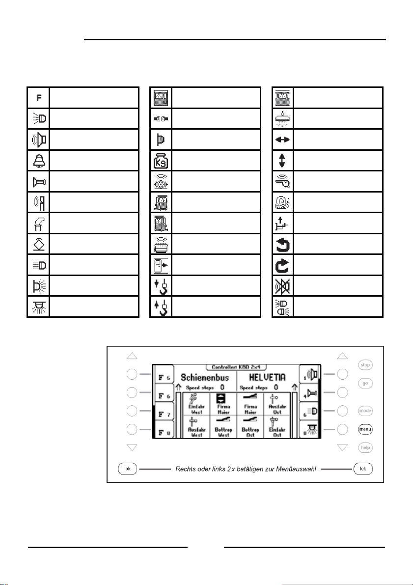
Intellibox II
Change Special function symbols
For displaying the special functions various symbols are available.
Preset: no Symbol Driver cabin lighting Interior Light
Light Uncoupler Magnet
Sound Tail Light Move right/left
Bell Start/Brake Inertia Move up/down
Horn Brake Squeal Conductor Whistle
Whistle Driver cabin - Rear Shunting gear
Smoke generator Driver cabin – Front Telex coupling
Power Pickup Diesel motor Turn left
High beam Doors Opening Turn right
Tail Light Hook Down Mute Sound
Interior Light Hook Up Light front and back
Procedure:
Step 1
62
Page 63
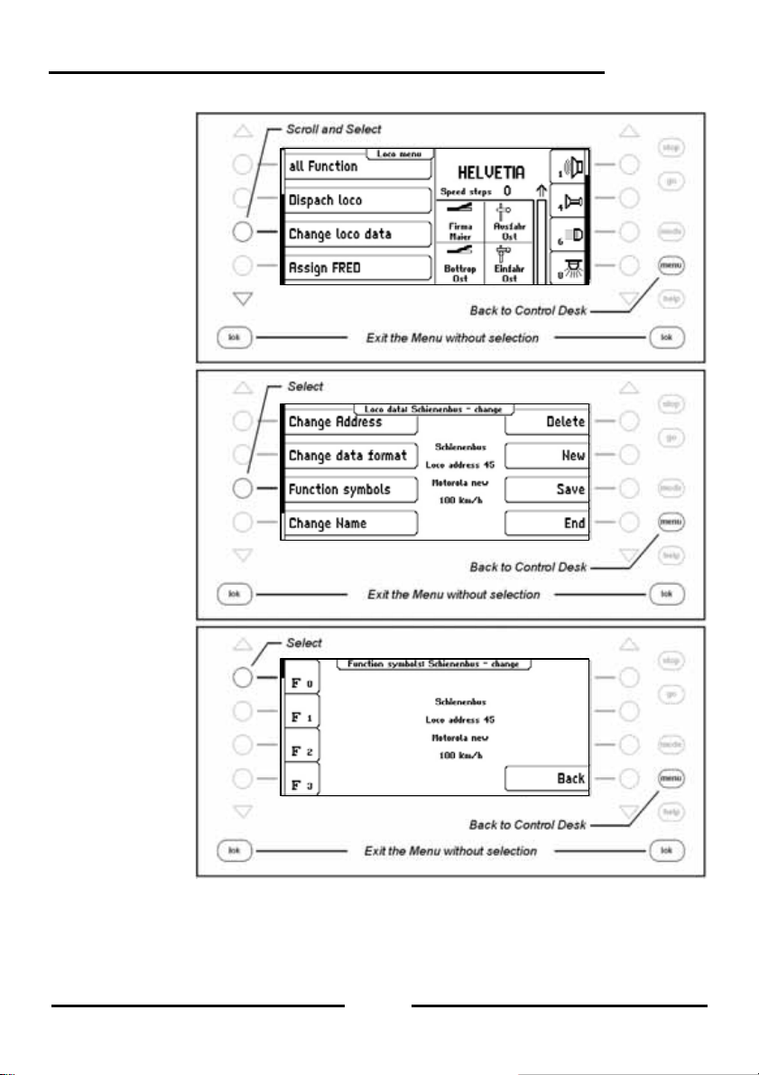
Step 2
Step 3
Step 4
Intellibox II
63
Page 64

Intellibox II
Step 5
Step 6
Step 7
64
Page 65

Change Top Speed
Step 1
Step 2
Step 3
Intellibox II
65
Page 66

Intellibox II
Step 4
Step 5
5.6.6 FRED Hand Controller
With the Intellibox II up to 16 FREDs (digital Hand controller from Uhlenbrock) in extended
in Mode (Controlling of up to four locom otives) can be operated. Addition al FREDs can be
connected in dispatch mode (Control of one locomotive) (see Chapter 5.6.4).
In the factory setting the Hand controller is configured so that on the Intellibox it can be
operated in extended mode.
The FRED Hand Controller Number
As soon as the Uhlenbrock Hand controller FRED is connected to the Intellibo x LocoNet
for the first time the center automatically assigns the FRED an internal Identification
number (ID). Using this hand controller number the center can forward locomotive
addresses to the FRED.
In the “Basic Setting – Hand Controller“ Menu (Chapter 4.5) the table with the in dividual
entered FREDs can be seen. Individual FREDs can also be d eleted from the table in this
Menu.
Forwarding a Locomotive address
If the FRED is used in extended mode the FREDs individual locomotive selection keys
have the locomotive addresses forwarded in the following way:
66
Page 67
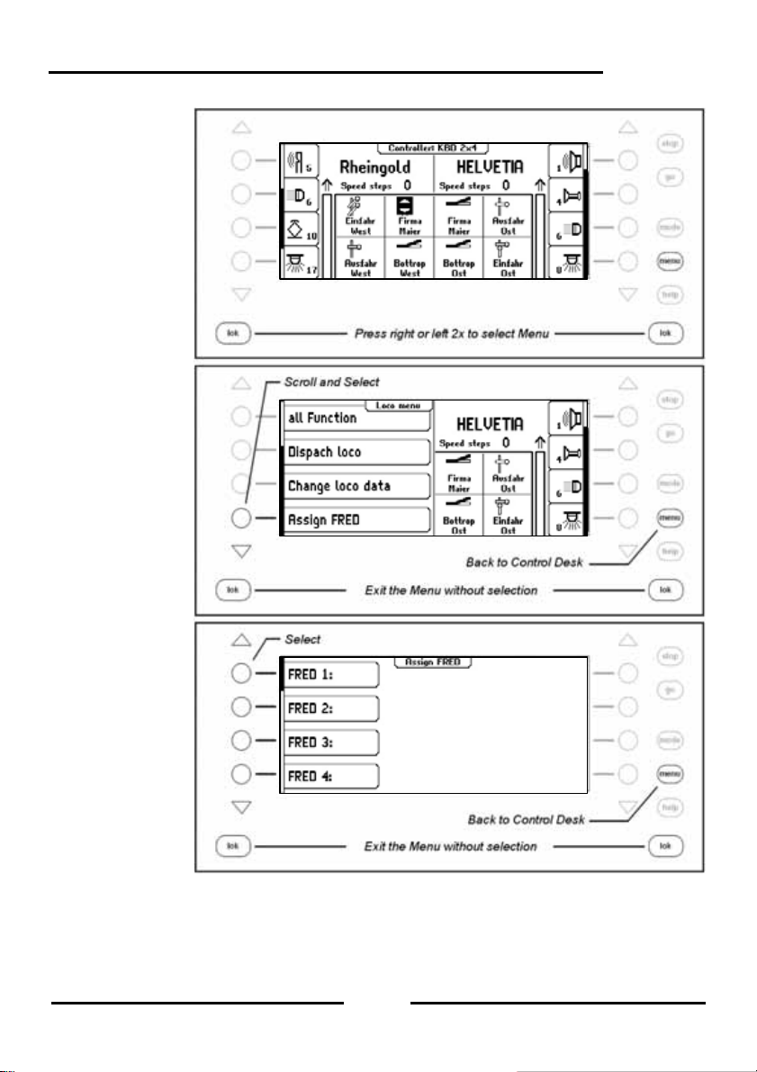
Step 1
Step 2
Step 3
Intellibox II
67
Page 68

Intellibox II
Step 4
Step 5
Step 6
68
Page 69
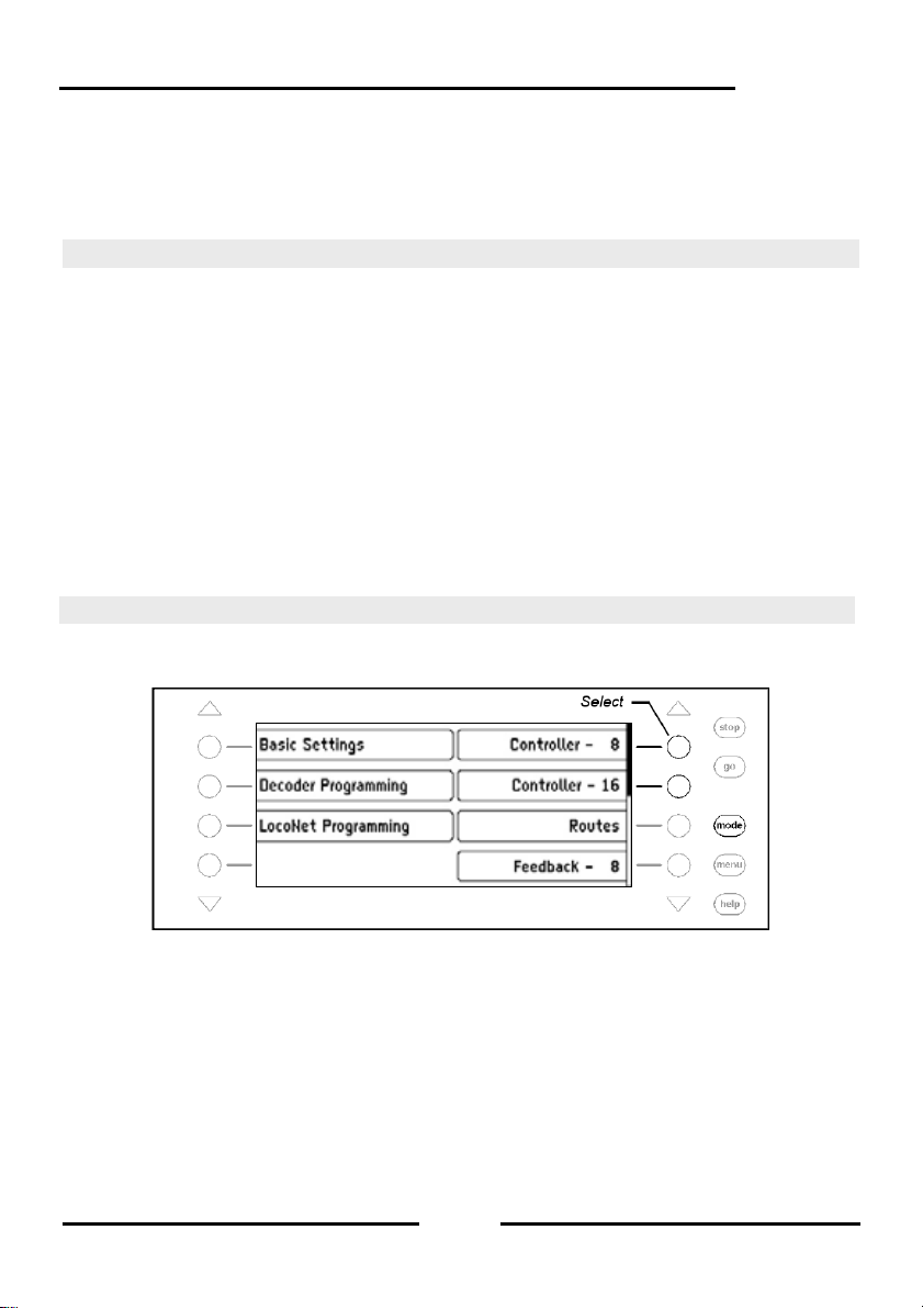
Intellibox II
6. The Switch Panel Mode
In a digital system turnouts and signals can also be controlled with an appropri ate decode r.
These are assigned an individual address just like a locomotive so that the system can
identify them.
6.1 Description
The Intellibox II can control turnout and switch decoders with different data formats, the
Motorola data format and DCC data format. Decoders of both data formats can be
operated side-by-side.
Turnout decoders from Märklin and Viessmann for Motorola d ata format each control four
turnouts.
Important: The address which is setup with the DIP switch on these decoders is not
identical to the addresses of the turnouts connected to the decoder. All setting menus in
the Intellibox II use the turnout addresses and not the turnout d ecoder addresses. A table
showing the relationship between the Dip switch setting and turnout addresses and also
the Märklin Keyboards is in the Appendix.
As is the case for locomotive decoders turnout and switch decoder ca n be configured for
the data format in the Intellibox II Basic Settings Menu without requiring any special
changes (see Chapter 4.4.1).
6.2 Select Switch Panel Mode
The Intellibox II has two Switch Panel modes the Switch Panel-8 Mode and Switch Panel16 Mode.
If the [mode]-key is pressed in Control Desk Mode, both modes can be selected from the
selection menu with display keys.
In Switch Panel-8 Mode, groups of 8 solenoids can be setup according to one’s wishes.
Each group can be assigned a name.
Each solenoid has two keys from the key block assigned to it. The respective solenoid is
switched to red with the red key and to green with the green key.
Each solenoid is represented in the middle of the display with its symbol, address and
individual name. How to assign a name and symbol to a solenoi d address is outlined in
Chapter 6.7.
69
Page 70

Intellibox II
In Switch Panel-16 Mode, groups of 16 solenoids can be set up according to one’s
wishes. Each group can be assigned a name.
Each solenoid is operated by one key in the key block and each key press toggles the
state of the solenoid from red to green or vice-versa.
Each solenoid is represented in the middle of the display with its symbol, address and
individual name. How to assign a name and symbol to a solenoi d address is outlined in
Chapter 6.7.
6.3 Operating a Switch Panel
Switch Panel-8
In the “Switch Panel-8” operating mode individu al switching functions of the Switch Panel
can be activated with the middle key block of the Intellibox II. Without any further input 8
turnouts, signals or switching functions are reachable.
Figure 6.31
Display and key block
with its numbering of
key pairs in Switch
Panel-8 mode
The individual switching functions are triggered by the red keys (rows 1. and 3.) or the
green keys (rows 2. and 4.) of the key block.
In the middle part of the display there is information about the actual status of the switch
panel. Every solenoid has a symbol which changes according to the state of the sol enoid.
It shows the state of a turnout or signal.
Switch Panel-16
In the “Switch Panel-16” operating mode individual switching functions of the Switch Panel
can be activated with the middle key block of the Intellibox II. Without any further input 16
turnouts, signals or switching functions are reachable.
Figure 6.31
Display and key block
with its numbering of
key pairs in Switch
Panel-8 mode
Each solenoid is operated by one key in th e key bl ock. Each key press t oggles the state of
the solenoid from red to green or vice-versa.
70
Page 71

Intellibox II
6.4 Configuring the Switching times
The switching pulse which is generated when the k ey is pr essed normall y lasts long as t he
key is pressed. In order to guarantee that the solenoids operates even with a n extremely
short key-press and that it is not damaged by a very long one the Intellibox II has a
minimum and maximum switching time setting. In factory setting switching time values are
a minimum of 100ms (0.1 sec.) and maximum of 5000ms (5 sec.). Both param eters can be
changed in the Intellibox Basic Settings Menu. See Chapter 4.4.2 “Switch Times”.
Note: For DCC decoders only the switching times that are not set on “Continuous
Operation” are affected.
6.5 Select a Switch Panel
Regardless if the Switch Panel-8 or Switch Panel-16 mode is active a switch p anel can be
called up by entering an address with which it starts and has the following 7 or 15
addresses depending on whether it is in Switch Panel-8 or Switch Panel-16 mode.
The assignment can be freely specified by the user in either mode. The Intellibox II can
store up to 64 groups. Each group has its own name. Thus for exampl e turnouts for entry
route can be assigned to a group and identified with the name Entry turnouts and always
simply called up by that name.
Procedure:
Step 1
Step 2
71
Page 72

Intellibox II
6.6 Setup and Edit a Switch Panel
The Intellibox II can administer up to 64 different Switches. Each S witch panel can have 8
or 16 chosen solenoids, turnouts or signals, assigned to it. Each Switch Panel is given a
name and can be selected with this name. Switch Panels be ne wly entered, edited and
deleted.
Note: If the switch panel was setup in Switch Panel-16 mode then only half will be
represented in Switch Panel-8 mode.
6.6.1 Setup a new Switch Panel
Procedure:
Step 1
Step 2
Step 3
72
Page 73

Step 4
Step 5
Step 6
Intellibox II
Step 7
73
Page 74
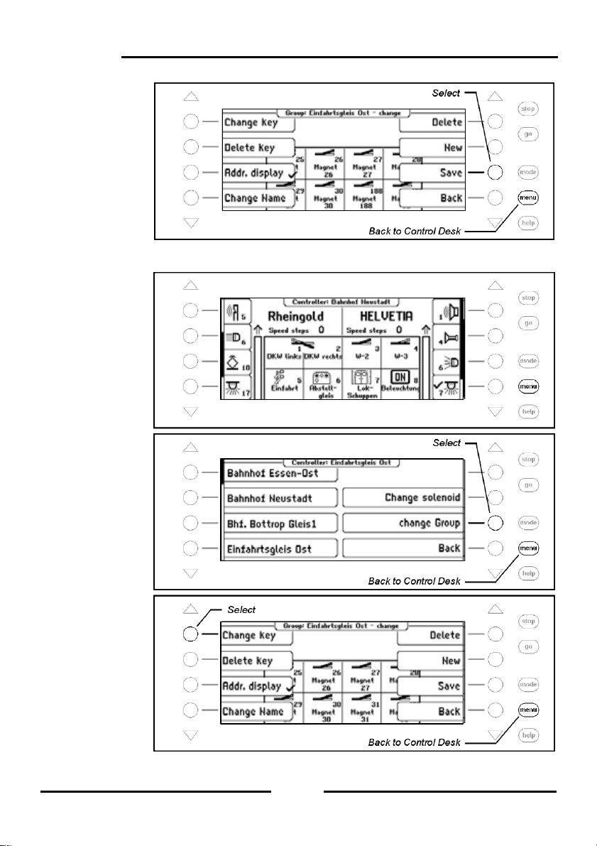
Intellibox II
Step 8
6.6.2 Edit Switch Panel
Step 1
Step 2
Step 3
74
Page 75
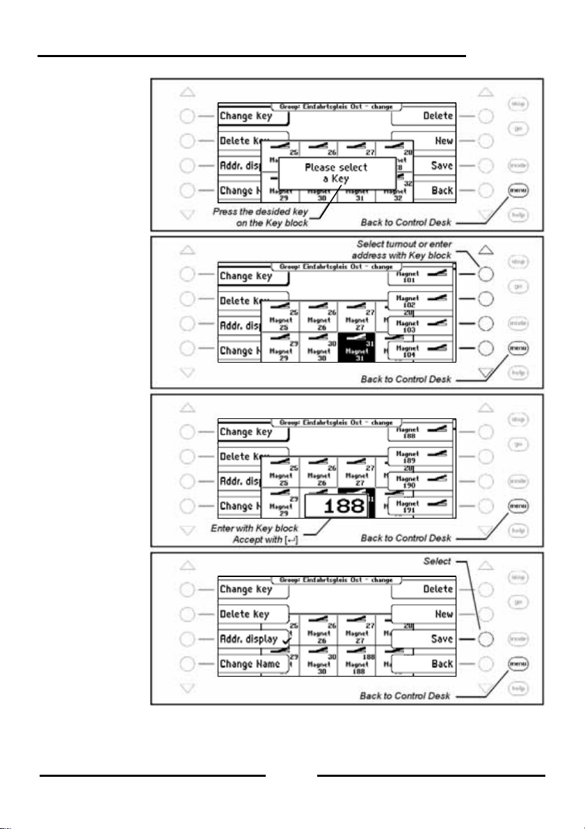
Step 4
Step 5
Step 6
Step 7
Intellibox II
75
Page 76

Intellibox II
6.6.3 Delete Switch Panel
Step 1
Step 2
Step 3
Step 4
76
Page 77

6.6.4 Switch Address Display on/off
Step 1
Step 2
Step 3
Step 4
Intellibox II
77
Page 78

Intellibox II
6.7 Set Name, Symbol and Data format of Solenoid addresses
Every solenoid address can have a name, a symbol and an individual Data format
assigned to it.
If no individual data format has been assigned for the ad dress the general data format is
used.
The changes can be made from the “Change Solenoid” Menu.
Procedure:
Step 1
Step 2
Step 3
78
Page 79
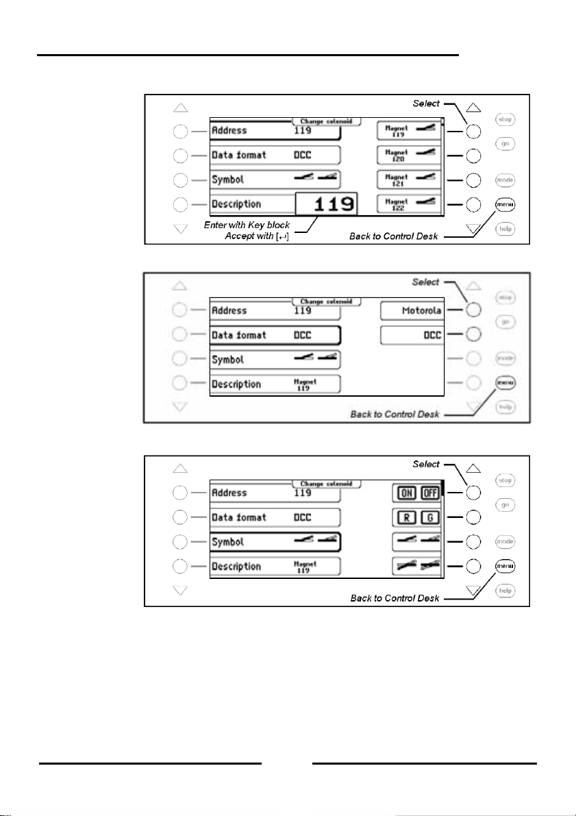
Select Solenoid Address
Step 4
Change Data format
Step 5
Change Symbol
Step 6
Intellibox II
79
Page 80

Intellibox II
Change Name
Step 7
Save Data
Step 8
80
Page 81

Intellibox II
7. The Route Mode
In a digital system, turnouts and signals, which are equipped with switch or solenoid
decoders, can be individually switched using appropriate input devices.
A particular route such as departing from a station’s track 1, usually requires that a
sequence of turnouts and signals be switched. These com mands can b e collect ed to get her
in route and switched by a single key from the Intellibox II key block or triggered by a
feedback.
7.1 Description
These can be switched with a key printing or by detailed feedback. Each route is represented by
its individual name in the display.
In route mode you have the possibility without the need f or additional devices, to store a
sequence of turnout and signal switching commands in a route. These ca n be switched by
pressing a key or a specific feedback message. Each route is represented in the display by
its individual name.
Up to 16 routes can be in a Group and can be switched by the 16 Keys in the Key block. A
maximum of 64 groups can be defined.
A total of 80 routes with 24 commands each can be defined in the Intellibox. Beyond that
additional routes can be called which are stor ed in e xternal devic es such a s IB-Control II or
IB-Switch.
For automatic layout control each route can be assigned a feedback message, so the route
can be switched by a running train. This way block sections and shado w stations can be
easily implemented.
7.2 Selecting Route Mode
When the [mode]-Key is pressed the Route Mode can be selected from the menu b y a
display key.
7.3 Selecting a Route Group
Up to 64 different groups with 16 routes can be defined. Each group is assigned a name b y
which the group can be selected. In the Intellibox II factory default setting five routes are
defined by name.
81
Page 82
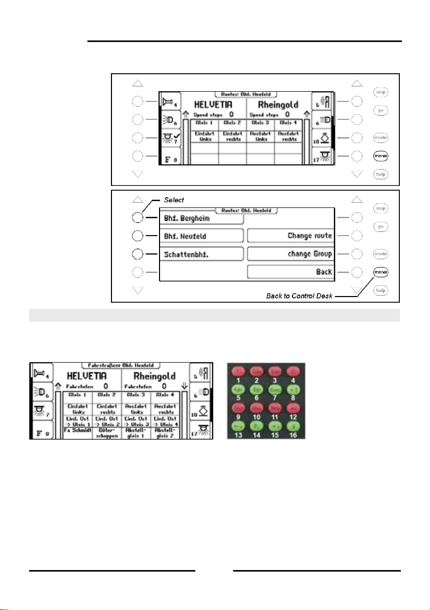
Intellibox II
Procedure:
Step 1
Step 2
7.4 Switching Routes
In Route mode each individual key in the Intellibox II central key block can switch a
programmed route. Press the [mode]-Key to select the Route Mode. Now the 16 respective
Keys in the middle key field show the routes.
Figure 7.41
Display and
Key block with
the numbering
of the keys in
Route Mode
By pressing one of these Keys the respective route is switched.
As soon as the route is selected the displayed name is inverted (white text and black
background), till all the contained switch sequence has been processed by the Intellibox II.
If there is no display for this Key in the selected gr oup the n no route h as been assigned, or
the route was not assigned with a feedback message.
82
Page 83

Intellibox II
7.5 Entering and Changing Route Groups
The Intellibox can administer up to 64 different route groups. Each route group can h ave a
collection of up 16 routes. Every route group has its own name and can be selected by this
name. Route group can be newly entered, changed and deleted.
7.5.1 Entering a new Route
Step 1
Step 2
Step 3
83
Page 84

Intellibox II
Step 4
Step 5
Step 6
Step 7
84
Page 85

Step 8
7.5.2 Change a Route Group
Step 1
Step 2
Step 3
Intellibox II
85
Page 86

Intellibox II
Step 4
Step 5
Step 6
7.5.3 Delete a Route Group
Step 1
86
Page 87

Step 2
Step 3
Step 4
Intellibox II
7.6 Programming Routes
Each route in the Intellibox II can contain up to 24 switching commands. One route can call
up another route as a sub-route. If a sub-route is called it is completely processed. Then
the remaining commands in the route are processed.
In place of switching commands the route can also conta in a Pause so that the following
commands can be delayed.
Routes can also send feedback messages so that routes stored in othe r devices like IBSwitch can be triggered.
Each route can have its own name so it can be identified easier. By assigning a feedback
address it can be triggered from feedback modules by running trains or manually.
87
Page 88

Intellibox II
Note: So that the route can be used it must always be given a feedback address.
Otherwise all the contents of the route are invalid and will not be shown in the Menus.
Attention: If a route is to be activated by the Infrared Remote Control IRIS the route’s
feedback address must be entered in the IRIS. For this the route in the Intellibox II must be
programmed with the feedback status “occupied”.
Procedure:
Step 1
Step 2
Step 3
88
Page 89

Select Route
Step 4
Change the Feedback message with which the route is switched
Step 5
Step 6
Intellibox II
89
Page 90
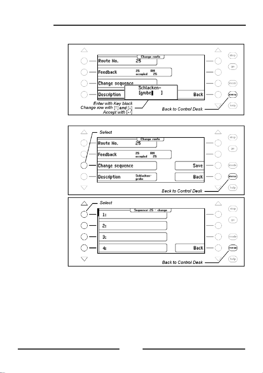
Intellibox II
Change Description
Step 7
Change Switching Sequence
Step 8
Step 9
90
Page 91

Enter Solenoid
Step 1
Step 2
Step 3
Intellibox II
Step 4
91
Page 92

Intellibox II
Insert Solenoid
Step 1
Step 2
Step 3
Step 4
92
Page 93

Step 5
Step 6
Insert Sub-Route
Step 1
Step 2
Intellibox II
93
Page 94
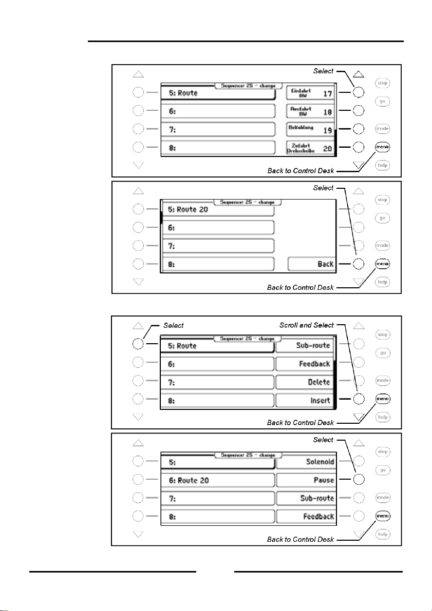
Intellibox II
Step 3
Step 4
Insert Pause in Seconds
Step 1
Step 2
94
Page 95
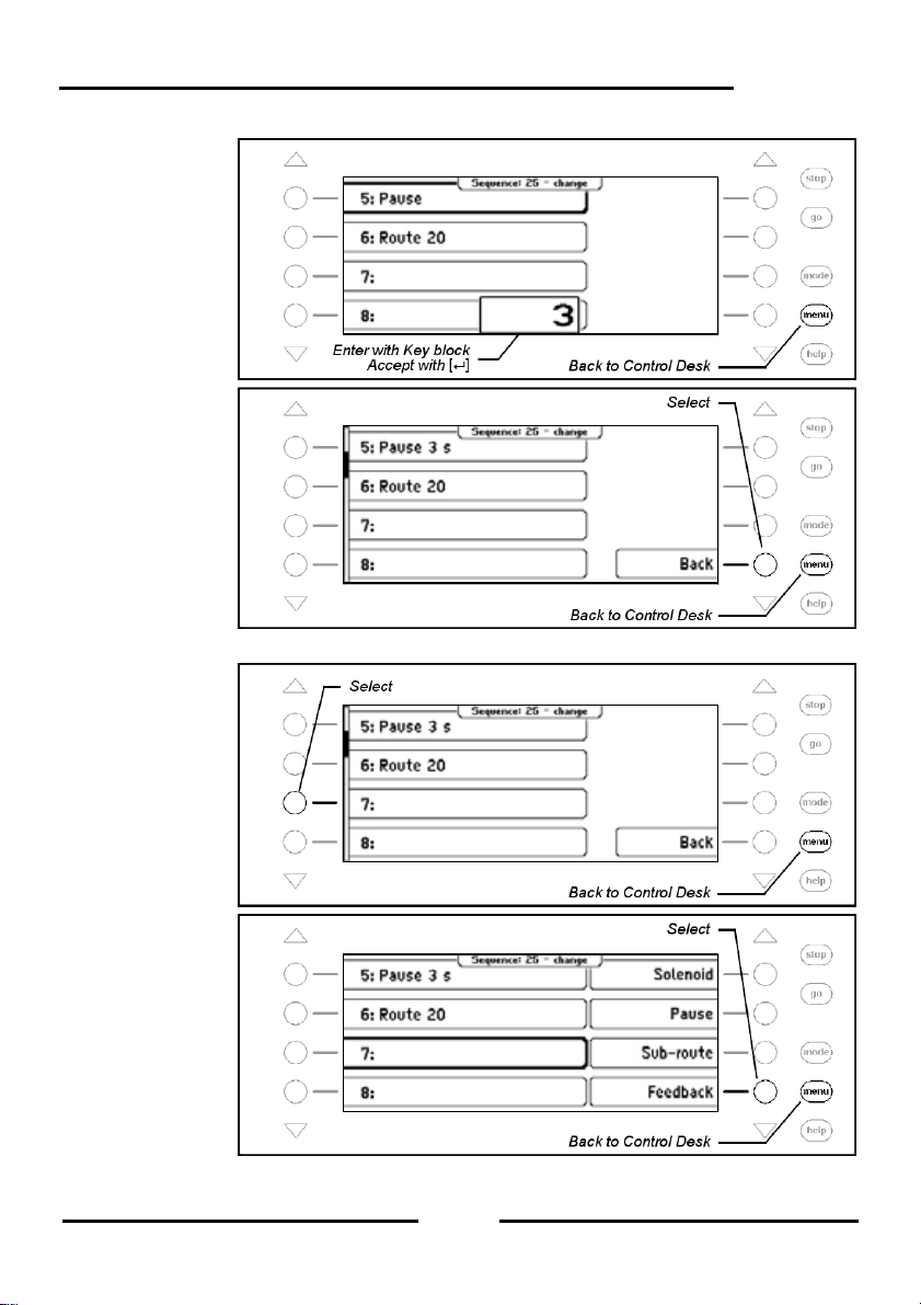
Step 3
Step 4
Enter Feedback
Step 1
Step 2
Intellibox II
95
Page 96

Intellibox II
Step 3
Step 4
Step 5
Delete a Route Entry
Step 1
96
Page 97

Step 2
Step 3
Save Route
Step 1
Intellibox II
7.7 Using Routes from an External Device
With the Intellibox you can also trigger routes form an external device suc h as those stored
in an IB-Switch or IB-Control II. For this you must assign the route with a route number
higher than 80. If you assign this route with the feedback message that will trigger a route
in another device then the defined route in a group can be assigned to a key on the
Intellibox. With this key you will then activate a route in another device.
For example a route is to be used which is stored in an IB-Switch and th ere is triggered by
feedback "250 occupied".
97
Page 98

Intellibox II
Procedure:
Step 1
Step 2
Step 3
Step 4
98
Page 99

Step 5
Step 6
Step 7
Intellibox II
Step 8
Now route 81 in a group can be assigned to a Key and in the example activates the 1.
Route in the IB-Switch.
99
Page 100

Intellibox II
7.8 Automatically activate a Route when the Intellibox starts up
When the power is switched on the Intellibox II can automatically activat e a route which
then runs the switching sequence when the layout is turned on. For this one of the 80
routes can be assigned as the “autostart” route. In the following example this is to be route
50.
Procedure:
Step 1
Step 2
Step 3
100
 Loading...