

Page 1
Page 2

by ZygÖmatiC
Introduction
3
Disclaimer
.......................................................................................
3 Installation
.............................................................................
3 Resources
........................................................................................
3
Behind the Name
............................................................................
3
User Interface
..................................................................................
4 Signal Flow
......................................................................................
5 Preset Browser
.................................................................................
5 Performance Control
.......................................................................
7 The Control Bar
...............................................................................
7 MIDI
................................................................................................
9
Section Reference
11
Oscillator Modulation (OSC MOD)
.................................................
11 Oscillators
........................................................................................
15 Mixer
...............................................................................................
16
Filter
................................................................................................
16
Miscellaneous (MISC)
.....................................................................
19 Low Frequency Oscillators (LFO 1 & 2)
............................................
22 Matrix
..............................................................................................
24 Envelopes (Env 1 – VCA & Env 2)
.................................................
26 Chorus
.............................................................................................
29 Modulation sources
........................................................................
31
Table of Contents
TABLE OF CONTENTS INTRODUCTION SECTION REFERENCE 2
Page 3

by ZygÖmatiC
Disclaimer
Installation
Resources
Behind the Name
Introduction
While making the user guide for Tyrell N6, material from different sources has been used,
namely, the user guide for u-he’s Hive synth. The section about Tyrell’s name was extracted
from Wikipedia.
To a careful reader sentences from Hive’s user guide, that have been adapted for the
purpose of this user guide, should be apparent, even though they’re not specifically marked.
Hive and Tyrell N6 are similar in many respects. The reason behind the usage of the
sentences from these sources is not plagiarism or stealing but the provision of accurate
information about the synthesizer that this guide is about.
Go to the Amazona webpage, scroll down until you see the Mac/PC/Linux download links
for the latest version of the plugin (v3.0 Rev. 3898). After you’ve downloaded the
compressed file, unzip it, run the .exe file and follow the onscreen installation instructions.
To uninstall, delete the plugin files and folders.
u-he online
For downloads, news articles and support, go to the u-he website
For heated debates about u-he products, go to the u-he forum
For friendship and informal news updates, go to u-he’s Facebook page
For u-he presets (payware and free), go to u-he preset library
For video tutorials and more, go to u-he’s YouTube channel
The Team
Peter Grandl, Mic Irmir – idea and concept
Urs Heckman & u-he – software development
Ryo Ishido, Marcus Steinlechner – GUI design
Stephen Gries – Tyrell’s hardware design
Jan Dziock – user guide in German
Bojan Milivojević – user guide in English
Special thanks to Tibor Devai for making sure that this user guide was written in
proper English.
By naming it Tyrell N6 (Nexus 6), the designers of the synth obviously wanted to
pay homage to the film Blade Runner. For those of you that haven’t had the chance to
watch it, it’s a famous 1982 neo-noir, cyberpunkish, science fiction film starring Harrison
TABLE OF CONTENTS INTRODUCTION SECTION REFERENCE 3
Page 4

by ZygÖmatiC
User Interface
Ford and featuring Vangelis as the film score composer and one of his most notable works
on the closing credits of the film.
The film is about genetically engineered replicants (androids). The Tyrell Corporation is
the fictional manufacturer of these replicants. The Nexus series replicants are virtually
identical to an adult human but superior in strength, agility and have variable intelligence
depending on the model. Nexus 6 replicants also have a safety mechanism, namely a four
year lifespan, to prevent them from developing empathic cognition and therefore immunity
to a special test which is the only method of replicant detection.
(Wikipedia)
Knobs, Sliders, Selectors
All knobs and sliders react consistently to left-click & drag and to up/down mouse
wheel scroll by activating the primary function, while a right-click will always open the
context menu whether the target is a knob, a slider or a selector.
Left-clicking on a selector shows that particular selector’s menu. Up/down mouse
wheel scroll while the mouse curser is hovering over a selector scrolls through the
selector’s options.
The right-click context menu consists of several functions. They are: Lock, MidiLearn,
MidiUnLearn and MouseWheel is rastered.
The Lock function guarantees that the value of a locked parameter will not change when
navigating through presets. Locked parameter will have a padlock icon over it. You are still
free to adjust the value of that parameter at any time.
The MIDI learn context menu consists of two options, MidiLearn and MidiUnLearn. After
choosing the MidiLearn option, make a change to a desired MIDI continuous controller
and the parameter will automatically be assigned to the selected function. If you wish to
free up an assigned MIDI continuous controller, right-click on the function it's been
assigned to and choose MidiUnLearn. Every function (knob, slider or selector) on the face
of Tyrell N6, except for the Matrix target selectors, is MIDI-controllable and can be
assigned to a different MIDI continuous controller. The assignments that you make for the
various control elements of Tyrell N6, will be globally stored in a file in the TyrellN6.data
plugin directory, so they can remain valid for the next time the host application is ran.
Set the MouseWheel is rastered option to “✔” if your mouse wheel is rastered (you can feel
it clicking slightly as you roll the wheel), so that each little click increments the value in
sensible steps.
To fine tune a parameter, hold down SHIFT before clicking on it. To reset a parameter to
its default value, use a double-click.
GUI Size, Text Antialiasing and Gamma
You can resize the GUI (Graphical User Interface) by right-clicking anywhere in the
background and selecting an option from the list. The sizes go from 840 x 420 pixels (70%)
to 2400 x 1200 pixels (200%).
Text Antialiasing switches the smoothing of labels and values on or off. Normally, it should
be left on. Only in certain cases will switching it off improve readability.
TABLE OF CONTENTS INTRODUCTION SECTION REFERENCE 4
Page 5
by ZygÖmatiC
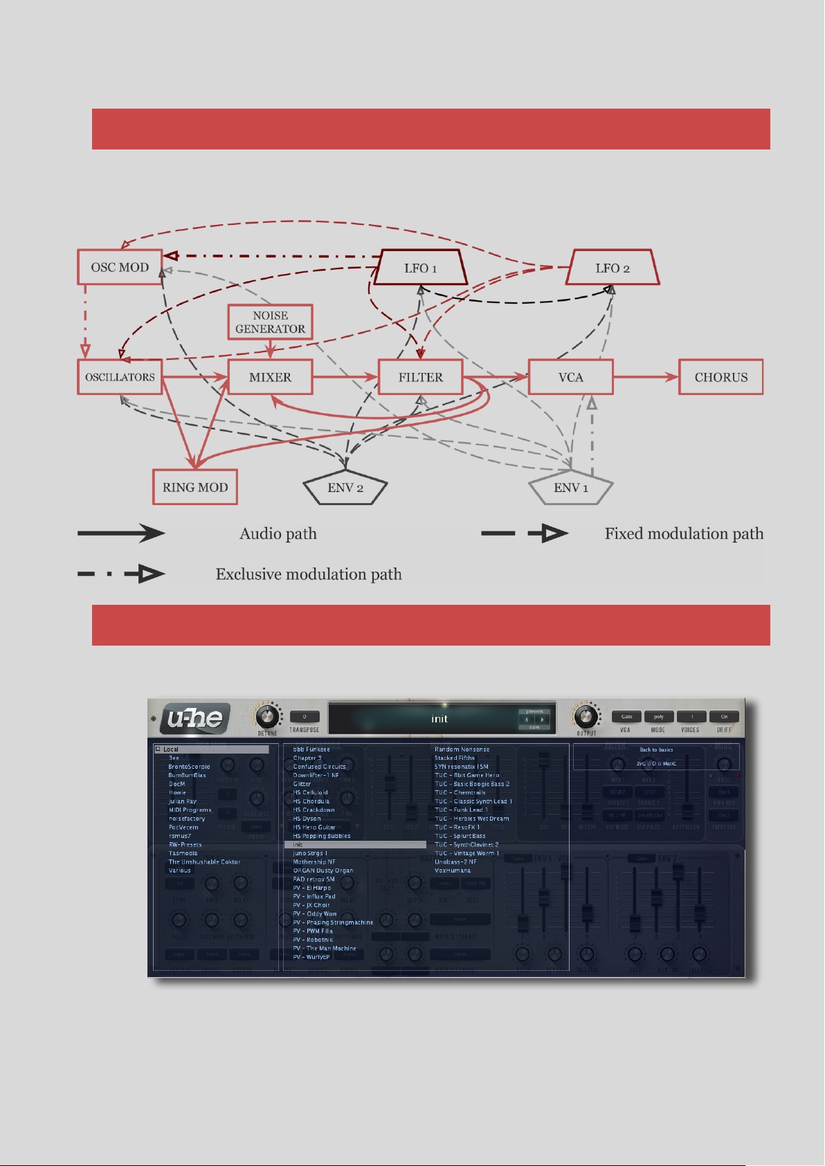
Signal Flow
The Preset Browser
Gamma determines how bright the GUI appears.
Suffice it to say that there are many modulation possibilities even without the Matrix. A
complete list of modulation possibilities can be found in a later section.
Presets
You can load any preset in the current folder by clicking on the data display (where it says
init on the picture above), or step through the presets by clicking on the arrow symbols on
the right-hand side of the data display. Tyrell N6 also includes a preset browser which can
TABLE OF CONTENTS INTRODUCTION SECTION REFERENCE 5
Page 6
by ZygÖmatiC
Local
This root folder contains a number of presets copied from
the various category folders to showcase Tyrell’s
capabilities. Here’s the list of abbreviations you may find
in the information section while trying the presets out:
MW – modulation wheel (MIDI CC #01)
BC – breath control (MIDI CC #02)
XP – expression pedal (MIDI CC #11)
AT – aftertouch (channel pressure)
PB – pitch bend
MIDI Programs
The main preset folder (Local) also contains a special
folder called MIDI Programs – you can go through the
presets in this folder using the MIDI Program Change
messages. For further details, see MIDI.
necessary after its folders or presets have been altered from
outside Tyrell.
Create new folder does exactly that – it creates a new folder
inside the current one.
Open in Explorer opens a standard OS window so you can use
be accessed by clicking on the Presets button, above the arrow symbols. Folders appear on
the left, presets are selected in the centre (which is scrollable), and the information about
each preset appears in the section to the right of the section where the presets are.
After choosing a preset, you can use the up/down cursors on your computer keyboard to
go through the other presets. Alternatively, you can use the pair of arrows to the right of the
data display.
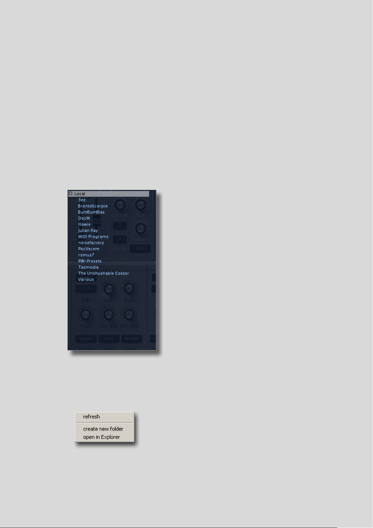
If you can’t see anything in the folders area (3ee, BrontoScorpio, BumBumBias etc.), click
on the small square to the left of Local.
To exit the browser, click on the Presets button again.
Save
Make sure that the folder where you want to store your preset is selected, then click on the
Save button underneath the Presets button and the arrow symbols.
Give your preset a suitable name and enter any other details you would like to appear in the
information area.
Folders Context Menu
Right-clicking in the folder list opens the same context menu as in the picture below this
text.
Select refresh whenever the contents of the browser need updating. This is always
your operating system’s file functions to add, rename, move, copy or delete presets. Always
remember to refresh afterwards!
TABLE OF CONTENTS INTRODUCTION SECTION REFERENCE 6
Page 7
by ZygÖmatiC
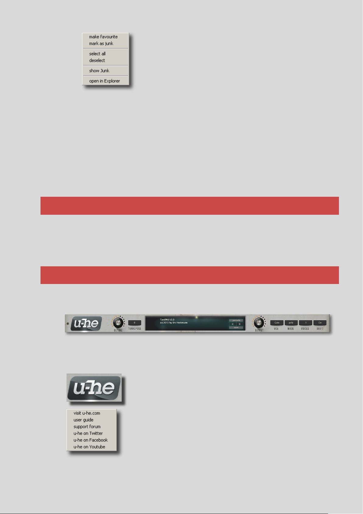
Presets Context Menu
Right-clicking in the preset list opens the same context menu as
in the picture to the left of this text.
The make favourite / mark as junk options are for marking
individual presets you particularly like or dislike. Favourite
presets appear with a small star next to their name. Junked
Performance Control
The Control Bar
Clicking on the u-he badge opens a popup menu containing links
to the user guide (that is missing), to the u-he homepage, to the u-
he user support forum as well as to u-he’s presence on various
social networks.
NOTE: Instead of directly opening the document, selecting user
guide in the popup menu to the left opens the folder where the
actual user guide should’ve been placed.
presets disappear but can be made visible again via show Junk. Of course you can “unjunk” and “un-favourite” marked presets.
The open in Explorer function opens an OS window so you can use on-board file functions
to add, rename, move, copy or delete presets. Always remember to refresh afterwards!
Select, Drag & Drop
Files can be moved from one folder to another via drag & drop. You can select multiple files
by using the SHIFT key on your computer or use the select all function in the presets
context menu to highlight all the presets in the folder. To remove all the highlights, choose
deselect from the presets context menu.
Tyrell N6 responds to the pitch bend (PB), modulation wheel (MW), breath (BC),
expression (XP), pressure (AT = aftertouch), as well as the hold (sustain) MIDI messages.
Most of the factory presets were specifically programmed for real-time performance using
those controls.
Along the top, on either side of the data display, Tyrell’s Control Bar hosts a range of global
parameters plus a few utility functions.
From left to right you will see the following...
The u-he Badge
TABLE OF CONTENTS INTRODUCTION SECTION REFERENCE 7
Page 8
by ZygÖmatiC
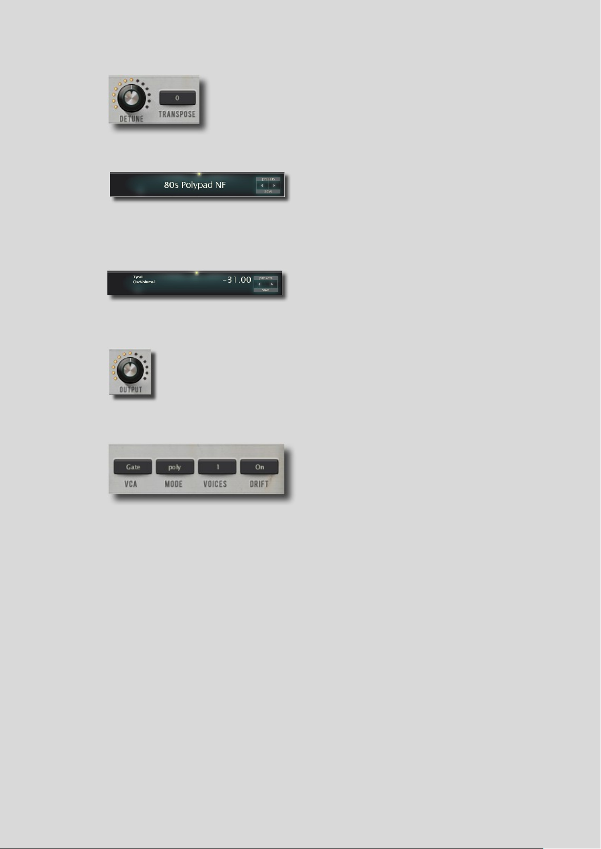
Transpose changes the pitch of the current preset in semitones
(+/– 24) while Detune does it in cents (+/– 50).
The Detune knob’s second function is to detune unison voices
against each other (Voices (unison) section).
The display has several functions, most of which
have to do with presets...
It usually shows the name of the current preset.
While you are adjusting something in Tyrell, the
data display shows the parameter’s name and
value. After a few seconds of inactivity, it will
show the name of the current preset again.
This is Tyrell’s main volume control.
Values higher than 100.00 can be used to boost inherently quiet signals to
normal levels.
There are two ways to control the synth’s VCA
(Voltage Controlled Amplifier), namely Gate and
ADSR 1 (ENV 1 – VCA). If Gate is chosen, the
volume of a note will instantaneously jump from
mute to full volume upon playing a key and back
Detune (fine tune) and Transpose
Data display
Clicking on the arrows on the right-hand side of the display navigates you through the
presets. Clicking on the display itself lets you select a preset from the current directory (see
Preset Browser above for a more flexible method). The Presets button opens up the Preset
Browser. Save button starts the process of saving your preset.
Output
VCA
to mute upon releasing the key. If you choose ADSR 1, the volume will progress according
to the shape of ENV 1 – VCA.
Mode (voice mode)
The poly mode option means normal polyphonic while mono and legato are monophonic
modes with different envelope triggering.
In the duo (duophonic) mode, the oscillator 1 plays the lowest held note while the oscillator
2 plays the highest. Both oscillators will play the same note if only one note is being played.
The highest and the lowest note have the priority in this voice mode.
There will be more on envelope triggering differences in the Envelopes section.
Voices (unison)
This selector determines how many voices will play in unison when a single key is pressed.
When adjusting the number of unison voices, bear in mind that Tyrell’s polyphony is set to
8 voices and can’t be changed. For example, if the Voices selector is set to 2, you’ll be able to
play 4 notes simultaneously before you run out of polyphony and note-stealing occurs. The
TABLE OF CONTENTS INTRODUCTION SECTION REFERENCE 8
Page 9
by ZygÖmatiC
MIDI (Musical Instrument Digital Interface)
less voices you utilize, the more CPU power you’ll end up saving.
If the Voices selector is set to more than 1, than the Detune knob, instead of acting as a fine
tune knob for the entire preset, assumes its second function which is detuning unison
voices against each other in positive or negative directions.
Unison voices, by default, do not have stereo spread. However, there is a hidden parameter
that can control it. It’s called VCA1: Pan. The easiest way to find it is to scroll through the
presets that come with Tyrell and find one that has this parameter chosen in one of the
modulation target slots of the Matrix section (e.g. TUC – Chemtrails). Now, reset every
parameter of the synth (double-click) except for that particular modulation slot. What you’ll
end up with is an initialized preset with the VCA1: Pan parameter available in the Matrix
section. You can even save that state of the synth as a preset for future use.
In order to spread the unison voices, make sure that the number of voices is more than one,
select StackVoice as a modulation source for VCA1: Pan and simply dial in the desired
amount of stereo spread (see the Matrix section).
Drift
The Drift function introduces slight imperfections in tuning of the synth’s oscillators in the
form of a slow wavering, mimicking the behavior of vintage analog synths.
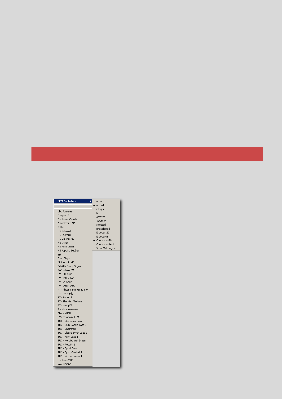
MIDI Controller Type Selection
Tyrell’s MidiLearn/MidiUnLearn function has been explained in the User Interface
section. Parameter’s response to the change of the value of a MIDI CC can be set via the
MIDI Controllers menu.
The menu to the left is the popup menu that’s available
when the synth’s display is clicked using the right mouse
button. It is almost identical to the left-click popup menu.
The only difference between them is the addition of the
MIDI Controllers sub-menu when the display is rightclicked.
If you are certain about the type of your MIDI controllers,
you will be able to choose the correct option from the
following:
Encoder 127 – unipolar encoder
Encoder 64 – bipolar encoder
Continuous7bit – the most common type of CC
Continuous14bit – the high resolution type of CC
Howere, if you’re not sure what type the encoders on
your MIDI control surface are, just leave it on
Continuous7bit, which is the default option and the most
common type of controller.
Parameter Behavior
A number of options in the MIDI Controllers sub-menu
set the behavior of a parameter controlled by a MIDI
controller. Thanks to the new revision of the plugin, all of
the bugs associated with this ability have been dealt with.
TABLE OF CONTENTS INTRODUCTION SECTION REFERENCE 9
Page 10

by ZygÖmatiC
Even though there are 8 different options to choose from, only 5 of them are actually worth
mentioning:
normal – the usual parameter behavior
integer – MIDI controller will sweep through the parameter’s entire range of
whole number values
fine – parameter’s value will be changed in 0.01 steps (limited range)
octaves – parameter’s value will be changed in 12.00 steps (limited range)
semitones – parameter’s value will be changed in 0.1 steps (limited range)
MIDI Program and Bank Changes
If your MIDI control surface or DAW can send MIDI Program/Bank Change messages, you
can use those messages to navigate through Tyrell’s presets.
In the preset browser’s Local folder there’s the MIDI Programs sub-folder (see MIDI
Programs) which is empty by default. It can contain presets of your choice that will be
switchable via MIDI.
To load up the folder, simply drag & drop presets from inside the preset browser. The folder
can contain up to 128 (0-127) presets. All 128 of them will be loaded into memory on the
startup of the plugin. Bear in mind that the contents of the folder can be changed on the fly
but the contents of the memory will be changed only upon the reinitialization of the plugin.
The presets are accessed via the Program Change messages in alphabetical order. If you
want to change the order of the presets in the list, simply rename them like any other file
using the open in Explorer option (see Folders Context Menu) and prefixing presets’ names
with 000, 001, 002...
The MIDI Programs folder can contain up to 127 sub-folders of 128 presets each. To go
back and forth between these folders, use Bank Select messages (CC#0). Bear in mind that
the MIDI Programs folder is bank 0. If you’re using banks, send Bank Select message
before the Program Change message.
A drawback of using Bank Select/Program Change messages via a typical MIDI
keyboard/control surface is that banks and programs have to be navigated through
sequentially. For example, if you wanted to get to the preset 120 and the number of your
current preset is 60, you would have to scroll through all the presets that are in between
those two. The same applies when you’re going down from a preset with a higher number to
a preset with a lower number.
The picture on the left shows
the format of what the display
will read when the synth
receives a Bank Select and/or a
Program Change message.
The first number from the left (3) denotes the selected bank, while the number to the right
of it (0) denotes the selected preset within that particular bank. The rest is the preset’s
name complete with the file extension.
TABLE OF CONTENTS INTRODUCTION SECTION REFERENCE 10
Page 11

by ZygÖmatiC
Oscillator Modulation (OSC MOD)
The oscillator modulation section (OSC MOD)
consists of the following controls...
Vibrato (VIBR)
This slider sets the amount of vibrato (cyclic
pitch modulation) for both oscillators, as well as
for the sub-oscillator. It is “hardwired” to the
LFO 1.
Tyrell’s pulse wave with a duty cycle of 50%
The same pulse wave with a duty cycle of 100%
Section Reference
Pulse Width (PW)
This slider adjusts the pulse width of the pulse waves of both oscillators. It doesn’t affect the
pulse width of the sub-oscillator.
At its topmost position, the slider corresponds to a wave’s duty cycle of 50%. At its
bottommost position, it corresponds to a duty cycle of 100%.
Pulse Width Modulation Source (PWSRC)
The PWSRC selector lets you choose what will be the source of pulse width modulation.
Clicking on it shows this popup menu:
TABLE OF CONTENTS INTRODUCTION SECTION REFERENCE 11
Page 12

by ZygÖmatiC
Every modulation target on this synth has these modulators as available
sources. More on modulation in later sections.
Pitchbend (PITCHB.)
Selects positive and negative pitchbend range in semitones. The range is
from 0 to 24 semitones in both directions. Pitchbend is controlled via
the pitchwheel on a MIDI keyboard or via a DAW.
Softsync
Oscillator sync is a feature that syncs the oscillators 1 and 2, making the
oscillator 1 the master and the oscillator 2 the slave. Every time the
master oscillator restarts its cycle, the slave oscillator’s phase will reset
regardless of its position. This technique ensures that the oscillators are
An example of the resulting (slave) pulse wave with a duty cycle of 50%
technically playing at the same frequency but the irregular cycle of the slave oscillator often
causes complex timbres and gives the impression of harmony.
Because of the complexity of the subject, only one version of oscillator sync will be covered
in this manual and that’s when the slave oscillator is higher in pitch than the master
oscillator.
When the Softsync (range) knob is at 100.00, the sync feature becomes hardsync. It means
that the two oscillators will sync together perfectly regardless of the phase difference
between them and the tuning of the slave oscillator. The Softsync parameter has to have the
value of at least 0.01 for the sync feature to become active.
At other positions, the matter becomes much more complex. The two oscillators will be
synced (producing harmonic results) only if the phase difference between them is within
the range specified by the Softsync knob.
The Softsync range is closely connected to the tuning of the oscillator 2 (Tune 2). When the
pitch of the slave is an integer of the master’s pitch, the output wave of the slave oscillator is
the same as its input wave. The Softsync range forms, in both positive and negative
TABLE OF CONTENTS INTRODUCTION SECTION REFERENCE 12
directions, around these integer pitches that correspond to these positions of the Tune 2
knob:
● 0.00 – the oscillator 2 is in unison with the oscillator 1, i.e. 1 x freq. (oscillator 1)
= freq. (oscillator 2)
● 12.00 – the pitch of the oscillator 2 is 12 semitones (an octave) higher than the
pitch of the oscillator 1, i.e. 2 x freq. (oscillator 1) = freq. (oscillator 2)
● 19.00 – the oscillator 2 is an octave and a fifth higher than the oscillator 1, i.e. 3 x
freq. (oscillator 1) = freq. (oscillator 2)
Page 13

by ZygÖmatiC
● 24.00 – the oscillator 2 is 2 octaves higher than the oscillator 1, i.e. 4 x freq.
(oscillator 1) = freq. (oscillator 2)
The higher the value of Softsync, the bigger that range will be and the bigger phase
difference between the oscillators is tolerated, which means that they will end up in sync
more frequently.
Pictures below are showing the harmonic content of the resulting slave square wave tuned
to 16.20 semitones above the master in different Softsync knob positions.
Softsync = 100.00 (above); Softsync = 90.00 (below)
TABLE OF CONTENTS INTRODUCTION SECTION REFERENCE 13
Page 14

by ZygÖmatiC
Softsync = 50.00 (above); Softsync = 15.00 (below)
In the case of phase difference being out of range, as shown in the second, third and fourth
picture above, different inharmonic overtones, depending on the position of the Softsync
knob, will start to appear in the resulting wave taking it out of harmony with the master.
The best explanation is offered by the sound itself. Here are some audio examples of how a
sync sweep sounds in various Softsync positions (click on the link to hear the audio files):
● Softsync = 100 (hardsync)
● Softsync = 90
TABLE OF CONTENTS INTRODUCTION SECTION REFERENCE 14
Page 15

by ZygÖmatiC
Oscillators
Wave Shapes (SHAPE 1 & SHAPE 2)
Tyrell N6’s oscillators 1 and 2 have continuously variable
waveforms (shapes). They are adjusted with the Shape 1 and
the Shape 2 knobs respectively.
The Shape 1 control offers four standard waveforms.
Beginning with the leftmost, they are:
➤ Sine
(1.00)
➤ Triangle
(2.00)
➤ Sawtooth
(3.00)
➤ Pulse
(4.00)
The same goes for the sub-oscillator.
● Softsync = 50
● Softsync = 15
Glide and Glide Offset (GLIDE OFST)
Glide aka portamento slurs the pitch of all oscillators between consecutive notes. The Glide
knob sets the amount of time it takes for the pitch to slur from one note to the next. The
time is always constant, regardless of the size of the played intervals.
The Glide Ofst knob offsets the glide time for the oscillator 2 in positive or negative
directions. In other words, it makes the offset time longer or shorter relative to the time
specified by the Glide knob.
Tyrell N6 has two oscillators as well as the sub-oscillator.
The oscillator 2 has only two waveforms controlled by the Shape 2 control. They are the
sawtooth and pulse waves.
The sub-oscillator is a stripped down version of the oscillator 1 with a frequency divided in
half. It’s a square wave, one octave lower in pitch than the oscillator 1.
NOTE: The symbol inscribed on the leftmost position of both shape controls can be a bit
misleading. It bears visual resemblance to a triangle wave. In the case of the first oscillator,
it’s actually a sine wave and in the case of the second one, a sawtooth wave.
Tunings and Tuning Modulation
Tune 2 is the knob that controls the tuning of the oscillator 2, a kind of control element that
the oscillator 1 lacks. Its range is from 0 to +24 semitones in 1-cent increments.
Fine is the fine tune control for the oscillator 2 with the range of +/-50 cents in one-
hundredth-of-a-cent increments.
The T-MOD 1 and T-MOD 2 knobs control the amount of oscillator tuning modulation for
the oscillator 1 (including the sub-oscillator) and the oscillator 2, respectively. The
modulator is set via the Source 1 and Source 2 selectors.
TIP: The T-MOD 1 knob can act as a tune parameter for the oscillator 1, with a short release
time, if its modulation source is set to Gate.
TABLE OF CONTENTS INTRODUCTION SECTION REFERENCE 15
Page 16

by ZygÖmatiC
Mixer
The Mixer is very straight forward. It
controls the volume of the six elements
going through it and the amount of each
going into the filter.
As Tyrell was designed to mimic the
behaviour of analog synths, its Mixer
augments that impression by allowing the
user to overdrive the filter. The Mixer’s
volume sliders go from -100.00 to
+25.00. The overdrive starts gradually
past the 0.00 point.
This is an example of how a sawtooth wave looks like on an oscilloscope at +25.00
Filter
Tyrell Nexus 6 features a self-oscillating
multimode filter with a unique Mixspr
(mixspread) function.
Cutoff (CUT)
The Cut slider sets or sweeps the filter’s
cutoff frequency (the point where the rolloff starts). The frequencies above and/or
below this point, depending on the filter’s
The Feedb. slider (feedback) mixes the signal that already went through the filter back into
the filter thus providing yet another level of sound distortion.
TABLE OF CONTENTS INTRODUCTION SECTION REFERENCE 16
mode, will be attenuated. The slider goes from 20Hz at its bottommost position (30.00) to
20kHz at its uppermost position (150.00).
Page 17

by ZygÖmatiC
Resonance (RES)
Resonance is the filter’s internal feedback loop that emphasizes the cutoff frequency
making those iconic filter sweeps possible.
Tyrell’s filter can mimic another capability of analog filters and that is self-oscillation. Self-
oscillation in a hardware filter occurs when a resonance control is set high enough that the
internal feedback causes the filter circuitry to become a sine wave oscillator. On this synth,
it gradually starts to happen around the Resonance slider’s 80.00 mark, whether the sound
is passing through the filter or not but only as long as the key is pressed.
VCF Mode, VCF Poles & Mixspread (MIXSPR)
The Mixspr control is probably the most unique feature on the entire synth. Its function is
determined by what is set with the VCF Mode and VCF Poles selectors.
The VCF Mode selector lets you choose between the LP/HP (Lowpass/Highpass) and BP
(Bandpass) modes with the lowpass being the filter that rolls off frequencies above the
cutoff point, the highpass the one that rolls off frequencies below the cutoff point and the
bandpass being, basically, a lowpass and a highpass filter together rolling off the
frequencies above and below the cutoff point that is controlled by the Cut slider.
The filter in the LP/HP mode functions as a lowpass and a highpass filter that are wired in
parallel with the Mixspr slider being the blend control between the two. In this case, the
Mixspr slider in its uppermost position only lets through the sound from the highpass filter.
In its bottommost position, on the other hand, it only lets through the sound from the
lowpass filter. Everything in between is a blend of the sounds from both filters with the Cut
control sweeping both cutoff frequencies.
NOTE: The VCF Poles parameter, in the above described case, is controlling the difference,
or rather the distance between the highpass and the lowpass cutoff points and not the
steepness of their roll-offs, as long as the Mixspr slider is not in its extreme positions. In
other words, when the Mixspr slider has a value higher than 0.00 and lower than 100.00,
by choosing the higher value VCF poles selector option, the only thing that will change is
the distance between the filters’ cutoff points. Take a look at the examples on the next page.
Selecting the BP mode changes things quite a bit.
The BP mode in combination with the 12dB/Oct VCF Poles setting turns the filter into a
bandpass filter with the cutoff slope of 12dB/Oct. In this case, the Mixspr control doesn’t do
anything.
The 24dB/Oct setting in combination with the Mixspr slider at its bottommost position,
doesn’t change the cutoff slopes of the bandpass filter to 24dB/Oct as one would expect.
Rather, it raises the filter’s output gain. If you start turning the Mixspr slider up, it
introduces another bandpass filter with its cutoff point moving up the audio spectrum along
with the Mixspr slider, while the cutoff point of the original bandpass filter, controlled by
the Cut slider, remains static.
This is how it looks and sounds like with the Cut slider static and Resonance ¾ of the way
up... (click here)
The 36dB/Oct setting on the VCF Poles selector only pushes the filter’s output gain further
up while the Mixspr slider is at its bottommost position. By turning the Mixspr slider up, a
second and, this time, a third bandpass filter will appear, one moving up the spectrum and
the other one down the spectrum, leaving the original filter in the middle, static.
Click here for the example.
TABLE OF CONTENTS INTRODUCTION SECTION REFERENCE 17
Page 18

Mixspr = 50.00; VCF Poles = 12 db/Oct
Mixspr = 50.00; VCF Poles = 24 db/Oct
by ZygÖmatiC
Mixspr = 50.00; VCF Poles = 36 db/Oct
TABLE OF CONTENTS INTRODUCTION SECTION REFERENCE 18
Page 19

by ZygÖmatiC
Miscellaneous (MISC)
The MISC section consists of a noise generator and a ring modulator,
both of them routed through the Mixer.
Noise Generator
The Noise Generator has a single control, a knob that blends different
types of noises.
At its leftmost position (1.00), it’s white noise while at its rightmost
(3.00), it’s red or brownian noise. Halfway between the two (2.00), the
noise becomes pink. The noise generated is mixed with other audio
sources via its dedicated volume slider in the Mixer section.
Visually, on a frequency analyzer, white noise is characterized by a flat
Filter’s Modulation Controls
(MOD 1, Source 1, MOD 2, Source 2 & Keyfollow)
The filter’s three groups of modulation controls consist of two knobs, MOD 1 and MOD 2,
two mod source selectors, Source 1 and Source 2 and the Keyfollow slider.
The MOD 1 and MOD 2 knobs set the extent of modulation in positive or negative
directions, while clicking on the source selectors shows the modulation source list common
to all mod selectors.
The Keyfollow modulation source can be used to modulate every changeable parameter of
the synth. However, the Keyfollow slider in the Filter section is dedicated to the modulation
of the filter’s cutoff frequency. It is, basically, the means of modulating the filter’s cutoff
frequency per MIDI note. The pivot note, i.e. the note that corresponds to the actual
position of the Cut slider and the note that the cutoff frequency modulation revolves around
is C4 (the middle C). Notes higher than the pivot note modulate the cutoff frequency in the
positive direction. In other words, the filter will “open” more the higher up the keyboard
you go, while the notes lower than the pivot note do it in the negative direction. The extent
of the modulation depends on how high the Keyfollow slider is set.
NOTE: The pivot note (C4) for the filter’s Keyfollow mod source is actually different than
the pivot note for the Keyfollow source used for modulating other parameters which is E3.
spectrum of all frequencies between 20Hz and 20kHz. To an average human ear, however,
this type of noise seems to be dominated by high-frequency content rather than low.
Red noise, on the other hand, is characterized, visually as well as aurally, by much warmer,
bottom-heavier tone than white noise.
Pink noise to a human ear has the same apparent loudness at all frequencies. Visually, it
has more lower-frequency content than white noise but less than red noise.
TABLE OF CONTENTS INTRODUCTION SECTION REFERENCE 19
Page 20

by ZygÖmatiC
White noise (above); red noise (below)
TABLE OF CONTENTS INTRODUCTION SECTION REFERENCE 20
Page 21

by ZygÖmatiC
Ring Mod selector menu
Input Src selector menu
Pink noise
Ring Modulator
A ring modulator is a device that multiplies the two signals sent to it, outputting the sum
and difference of their frequencies. Ideally, there should be no frequencies of the input
waves present in the output wave, only their sum and difference.
Ring modulation is a form of amplitude modulation. The result of it is a wave, harmonically
very rich, whose harmonics, depending on the relationship between the frequencies of the
two waves being multiplied, may or may not be harmonically related.
The two signals are generally called a modulator and a carrier. The modulator is the source
of ring modulation while the carrier represents the destination. In the case of Tyrell N6,
they are called Ring Mod (the carrier) and Input Src (the modulator). The output of the
Ring Modulator is mixed back with other audio sources in the Mixer section.
NOTE: The oscillators are not sacrificed for the purpose of ring modulation. They can still
be used as sound sources on their own even when the ring modulator is being used.
Here are the lists of available modulators and carriers...
TABLE OF CONTENTS INTRODUCTION SECTION REFERENCE 21
Page 22

by ZygÖmatiC
Low Frequency Oscillators (LFO 1 & LFO 2)
The topmost selector that selects a waveform for the particular LFO.
It has a dropdown menu with available waveforms.
The first two waves are regular sine and triangle waves.
The saw up is an ascending, while the saw down is a descending
sawtooth wave.
The sqr hi-lo is a square wave that starts in its high (positive) state.
The sqr lo-hi is a square wave that’s 180° out of phase with the sqr
hi-lo wave. In other words, the sqr lo-hi waveform starts in its low
Tyrell’s LFO (Low Frequency Oscillator) section features two identical LFOs that are used
as modulation sources. LFO 1 is “hardwired” to the vibrato function.
Each LFO features a number of selectors and sliders and they are:
Waveform (unmarked)
(negative) state.
The last two waveforms do not have a particular cyclical shape. Their amplitudes consist of
values randomly chosen by the synth with a defined maximum. That is why they are called
random waveforms.
An LFO with rand (random) hold selected uses the sample and hold method to modulate its
target. It samples a random value within a range determined by a specific modulation
amount controller (e.g., the Vibr slider) for a particular modulation target and holds that
value for the amount of time specified by the LFO’s Rate knob.
The only difference between rand hold and rand glide is that an LFO with rand glide
selected, instead of holding, smoothly glides between randomly sampled values.
TABLE OF CONTENTS INTRODUCTION SECTION REFERENCE 22
Page 23

by ZygÖmatiC
Sync
The Sync selector offers non-synchronized times (scale factors)
measured in seconds (0.1s, 1s, 10s) as well as a long list of values
synchronized to the DAW’s tempo, that includes dotted times (50%
longer notes) and triplets (3 notes in the space of 2).
Rate
It shifts LFO’s speed in a positive or a negative direction relative to the
value set by Sync. LFO’s highest frequency, when the 0.1s scale factor is
selected, is well in the audio range, ≈150Hz. Its lowest frequency with
the 10s scale factor is ≈0.007Hz. LFO’s Rate can be pushed beyond
these frequencies using the Rate Mod knob with a modulation source
like Gate.
A value selected by the Sync selector corresponds to the center position
of the Rate knob. Positive and negative integer Rate values further
divide (positive Rate values) or multiply (negative Rate values) a
synchronized time set by the Sync selector.
For example, if Sync is set to ¼, +1.00 on the Rate knob would mean
that the LFO will oscillate as if Sync was set to ⅛, i.e. twice as fast. On
the other hand, if the Rate knob was set to -1.00, the LFO would
oscillate as if the Sync knob was set to ½, i.e. the LFO’s frequency will
be halved.
Delay
This parameter’s name is a bit misleading. Delay doesn’t introduce a
delay into an LFO’s phase. It rather fades in the LFO’s amplitude. The
Restart
Selects a rule to reset the LFO phase...
Sync – LFOs of all voices are synchronized to the host DAW, so they all
adopt the same phase. The phases of LFOs can still be modulated apart
Delay feature simply fades in the amplitudes of the sine, triangle, saw up and saw down
waveforms.
With square like waveforms (sqr hi-lo, sqr lo-hi and rand hold) it introduces a glide
between the initial amplitudes as well as a fade-in of those amplitudes and all that only
during the “delay” period.
With rand glide, the Delay function simply fades-in the LFO’s amplitude.
TABLE OF CONTENTS INTRODUCTION SECTION REFERENCE 23
Phase
It lets you specify at which point of its cycle the LFO’s waveform will start, i.e. it determines
its phase.
While the Phase knob is at its leftmost position (0.00), there’s no phase shift and the
waveform will start at the zero point. If you turn the knob all the way to the right (100.00),
there will be a 360° phase shift. In other words, the phase will be identical to the phase at
the knob’s leftmost position. At the knob’s middle position (50.00), the shift of the LFO’s
phase will be 180°, meaning that the polarity of the waveform will be inverted.
per voice by a polyphonic mod source such as Velocity, KeyFollow or Random via the
Matrix.
Gate – Each note played restarts the LFO for each voice independently. Restarted LFOs will
adopt the phase set by the Phase knob.
Page 24

by ZygÖmatiC
Matrix
XS – Mod OSC 1
It’s also called cross modulation. Using the
Depth knob to define the amount of modulation
applied and via a selectable modulation source
(the Via selector), a targeted parameter (Dest)
will be modulated by the oscillator 1. Therefore,
the oscillator 1 becomes a modulator like the
LFOs. The most important differences between
modulating a target using an LFO and a regular
oscillator intended for sound generation is that
the regular oscillator modulates the target at the
frequencies that are in the audio range and it can
be an audio source at the same time.
Depth sets the amount of modulation applied by
the oscillator 1. At its leftmost position, the
1
2
1
2
Single – Like Sync, all voices share the same LFO, which is restarted at the next MIDI
note after all previous notes have been released.
Random – Notes restart the LFO for each voice independently at a random phase, ignoring
the value of Phase.
Rate Mod
Rate Mod consists of two controls, the Rate Mod knob and the modulation Source selector,
used for modulating LFO’s Rate.
The Rate Mod knob sets the intensity as well as the polarity of the modulation. When at its
center, there’s no modulation.
Clicking on the modulation Source selector shows the list of available modulation sources.
NOTE: LFO 2 can be used to modulate LFO 1 only via the Matrix.
Depth Mod
It is an LFO amplitude control, i.e. it can turn down the amount (depth) of modulation, and
it works rather counter intuitively.
When the Depth Mod knob is at its leftmost position (0.00), LFO’s amplitudes are at their
maximum. Turning the knob to the right turns the amplitudes down progressively. At the
knob’s rightmost position (100.00), there’s no modulation at all because the LFO’s
amplitudes are equal to zero.
Accompanying the Depth Mod knob, there’s a modulation Source selector. Again,
LFO 1 cannot be modulated by LFO 2 using this modulation source selector.
When using a modulation Source to modulate LFO’s amplitude, the position of the Depth
Mod knob will actually determine the minimum amount of modulation applied by the
Source while the maximum always remains the same.
Matrix further augments Tyrell’s modulation possibilities. It consists of two not so clearly
defined sub-sections, the XS – Mod OSC 1 sub-section and below that, the actual
modulation matrix sub-section.
TABLE OF CONTENTS INTRODUCTION SECTION REFERENCE 24
modulation is turned off.
Page 25

by ZygÖmatiC
Matrix Target main
menu
VoiceCircuit menu
ADSR 1 & 2 menu
LFO 1 & 2 menu
Tyrell menu
Via is the selector that determines which modulation source will be used to modulate the
depth of cross modulation. When the Via selector is clicked, the common modulation
source list appears. If you, for instance, select Velocity as your Via modulation source, then
the current position of the Depth knob (only if it’s higher than 0.00) will correspond to the
Velocity value of 127 (or 128 depending on your DAW) while the Velocity value of 0 (or 1)
will correspond to no cross modulation (Depth = 0).
Dest (destination) selects a target for cross modulation. There are three possible cross
modulation destinations:
1. OSC 2 FM
2. OSC 2 PWM
3. Filter FM
OSC 2 FM stands for frequency modulation of the oscillator 2 by the oscillator 1.
OSC 2 PWM selects the pulse width of the oscillator 2’s pulse wave as a modulation target
for the oscillator 1.
Filter FM turns the filter’s cutoff (Cut) into a modulation target for the oscillator 1.
The results of these cross modulations are quite different compared to the results of
modulating the same targets using an LFO mainly because the oscillator 1 has a much
higher frequency. The rate of modulation is equal to the pitch of the oscillator 1.
Modulation Matrix
It offers a modulation solution for almost every parameter that is controlled by a knob or
slider on the face of the synth, including the Chorus section’s knobs (Rev. 3898). The
Matrix knobs are excluded. Modulating a parameter that is controlled by a selector also
isn’t possible.
These are the available modulation targets (right-click on the Matrix target selector)...
TABLE OF CONTENTS INTRODUCTION SECTION REFERENCE 25
NOTE: In order to have ADSR 1 and ADSR 2, as well as LFO 1 and LFO 2, available in the
Matrix Target main menu, they all have to be selected at least once by any of the synth’s
Page 26

by ZygÖmatiC
Envelopes (Env 1 – VCA & Env 2)
modulation source selectors.
New in the Rev. 3898 of the synth is the ability to choose the modulation target by leftclicking and dragging the target cursor to the desired modulation target.
The modulation matrix consists of two horizontal groups of controls. For the lack of the
official term, I’ll name them Matrix 1 and Matrix 2. Each group has a Matrix Target
selector and two modulation amount knobs with the accompanying modulation source
selectors underneath. Two parameters can be modulated separately and simultaneously.
The Matrix Target selectors determine which parameter will be a modulation target.
Knobs on the left-hand side of the Matrix section, marked with the number 1 on the page
23, set the amount of modulation of the target selected by the Matrix Target selector, each
for its own Matrix group. The source of modulation is determined by a selector sitting
beneath each knob.
Knobs to the right, marked with the number 2, set the amount of modulation of a
modulator. These knobs also have a modulation source selector underneath.
The last two modulation sections on the face of Tyrell N6 are the envelope generators.
These envelopes are 4-stage envelopes with some additional controls and they act as
modulation sources.
ENV 1 – VCA is labeled VCA because it is hardwired to the Voltage Controlled Amplifier
and it’s the envelope for controlling the volume of the synth. However, it can be used to
modulate other parameters as well.
These are the envelope controls...
Attack (A), Decay (D), Sustain (S), Release (R)
These four sliders are the envelopes’ four main controls for shaping the volume progression
of a sound and/or the progression of parameter’s modulation.
Attack (A) – the time it takes for a parameter to go from a defined minimum level to a
defined maximum level after a note is played. The minimum level is defined by the position
of parameter’s level knob or slider. The maximum level is defined by the value of the
parameter’s dedicated modulation amount knob, e.g. MOD 1, MOD 2, Rate MOD...
Decay (D) – the time it takes for the parameter to reach the Sustain (S) level after the
Attack stage. NOTE: If the Sustain is at maximum, there will be no Decay stage, no matter
which position the Decay slider is at.
Sustain (S) – the level of volume or modulation an envelope will hold after the Decay stage
TABLE OF CONTENTS INTRODUCTION SECTION REFERENCE 26
Page 27

by ZygÖmatiC
Schematic of Tyrell’s ADSR envelope (FallRise=0)
Schematic of Tyrell’s ADSR envelope with FallRise engaged
for as long as the note is being held, i.e. for as long as the gate is open but only if the
FallRise knob is at its center position.
Release (R) – the time it takes for the parameter to return to the pre-Attack level after the
note is released.
FallRise
This function radically changes the behavior of an envelope’s Sustain. It can turn an
envelope into a quasi 5-stage envelope. What happens to the amplitude of a parameter
modulated by an envelope when it reaches the Sustain level (S) is determined by the value
of the envelope’s FallRise knob.
TABLE OF CONTENTS INTRODUCTION SECTION REFERENCE 27
Page 28

by ZygÖmatiC
The FallRise knob goes from -100.00 to +100.00. When centered, the FallRise parameter is
disengaged. When in its positive range, from +0.01 to +100.00, the amplitude of the
parameter that’s being modulated, after it reaches the Sustain level, will start to Rise until it
reaches the envelope’s maximum and hold it for as long as the key is pressed. The opposite
will happen if the FallRise parameter is in its negative range, from -0.01 to -100.00. The
amplitude will start to Fall until it reaches the envelope’s minimum and hold it for as long
as the key is pressed.
The Rise and Fall times are determined by the value of the FallRise knob. The higher the
knob’s positive value is, the shorter the Rise time will be. The opposite is true for the Fall
times. The higher the negative value is, the shorter the Fall time will be.
NOTE: If Sustain is already at maximum, turning the FallRise knob up won’t change
anything. There will be no Rise. The same is true for Fall, if you try to turn the knob down
while Sustain is already at minimum.
Trigger (unmarked)
It’s the top-left selector that sets what will trigger an envelope. ENV 1 – VCA has four
Trigger options available, while ENV 2 has five. The options are: Gate, Single (ENV 2 only),
Loop, LFO 1 and LFO 2. How an envelope reacts is also determined by the Mode (voice
mode) the synth is in.
Gate – The term is borrowed from older analog designs that used this method for triggering notes using voltage.
Gate (trigger) + poly (voice mode) – the envelope will be triggered whenever a key is
pressed. The Release stage begins when the note is released.
Gate + mono – the envelope exhibits the same triggering behavior as in the Gate +
poly mode, except in the cases when the Attack and Release times are higher than 0.00
and played notes overlap due to the length of the Release time. In those cases, a new
envelope will be triggered for every new note but it will start its run at the point where
the envelope of the previous note left off, even during legato playing.
Gate + legato – the difference between the legato and mono voice modes in terms of
envelope triggering can be heard only during legato playing (playing a note with the
previous one still depressed). In the legato mode, an envelope will be triggered only for
the first note in the sequence of notes that have been played legato, i.e. all other
consecutive notes will share the envelope of the first one.
Gate + duo – The duo mode has no envelope triggering differences compared to the
mono mode while single notes are being played. On the other hand, it exhibits the
same envelope triggering behavior as the legato mode while 2 notes are being played.
Single (ENV 2 only)
Single + poly – a new envelope will be triggered for every note played in a non-legato
manner regardless of the ENV 2 Release time. If the notes are played in a legato
manner, they will share the same envelope until all the notes from that particular
legato sequence have been released.
Single + mono / legato / duo – The envelope 2 triggering behavior will be the same as
in the Gate + legato mode.
Loop – the trigger mode in which an envelope will continuously run through its stages in a loop, for as long as a key is pressed. The FallRise stage can also be a part of a loop.
NOTE: If the Sustain slider is at its minimum or when the FallRise knob has a negative
value, the Release stage will be skipped while an envelope is looping. However, the Release
TABLE OF CONTENTS INTRODUCTION SECTION REFERENCE 28
Page 29

by ZygÖmatiC
Chorus
stage won’t be skipped if the held note is released in the middle of the envelope’s run (loop).
If the Sustain slider is at its maximum, the Decay stage will be skipped during looping.
Loop + poly – an envelope will be triggered for each note played. Therefore, each
note’s envelope will have a loop whose starting point is relative to the starting point of
each note.
Loop + mono / legato / duo – the same as in the Gate + mono / legato / duo modes
respectively, except the fact that an envelope would loop continuously if a note is being
held.
LFO 1 & LFO 2 – an envelope will be retriggered in time with each new cycle of the LFO 1
or LFO 2 regardless of which stage an envelope is at.
When an LFO is used to trigger an envelope, different triggering patterns can be achieved
just by modulating the Phase knob of the particular LFO.
LFO 1 or LFO 2 + poly / mono / legato / duo – in all of these modes an envelope will
exhibit the same retriggering behavior.
NOTE: In the Rev. 3898 of the synth the unpredictable buggy behavior of this envelope
triggering mode has been fixed.
Velo (velocity)
This parameter determines how strongly the envelope’s output level is affected (modulated)
by MIDI velocity.
In the case of ENV 1 – VCA, the Velo knob always sets how much the incoming MIDI
velocity data affects the output of the VCA. The bigger the value of the knob is, the bigger
the difference between softer keystrokes and harder keystrokes will be in terms of the
actual output volume or the amount of modulation of a parameter.
If the envelope 1 is modulating additional parameters, the amount of modulation of those
parameters will also be affected by the setting of the Velo knob.
Keytrk (keytrack)
This parameter, unfortunately, hasn’t been revised in the new revision of the plugin. It is
still mislabeled. According to the current label, its function should be to scale the Attack,
Decay, FallRise and Release times according to the MIDI note number. What it actually
does is that it scales those times according to the MIDI velocity value.
The Keytrk knob has positive and negative ranges. The parameter is disengaged when the
knob is in its center position.
When the knob is in the positive range, the higher the velocity value is, the longer the
envelope times will be. The exact opposite happens when Keytrk is in the negative range.
The higher the MIDI velocity value is, the shorter the envelope times will be.
Chorus effect occurs when individual sounds with approximately the same timbre and very
similar pitch converge and are perceived as one. Similar effect can be reproduced by playing
both oscillators while one is slightly out of tune with the other. Along the bottommost edge
of its user interface, Tyrell N6 has a dedicated Chorus section for this type of effects.
Tyrell’s chorus is a stereo chorus and, like most other choruses, it produces its effect by
TABLE OF CONTENTS INTRODUCTION SECTION REFERENCE 29
Page 30

by ZygÖmatiC
splitting (copying) the incoming signal into several signals, delaying the copied signals by a
small amount (≈20-50ms) and modulating that delay amount with a dedicated LFO.
On/Off (unmarked)
The leftmost control of the Chorus section is the convenient on/off switch. By including this
switch, the designers of the synth allowed the user to quickly and elegantly compare sounds
with and without the chorus over them.
Type
Just like in Diva and Hive, there are three types of choruses available, Classic, Dramatic
and Ensemble. Each type is a multi voice chorus based on a particular hardware unit.
Classic and Dramatic are two variations of the same chorus algorithm with Dramatic being
the type with more apparent detuning.
Ensemble’s characteristics make it similar to the chorus effects used in string machines.
Rate
Tyrell’s chorus has its own LFO and the Rate knob controls its frequency.
LFO’s job is to modulate the delay between the original signal and the delayed (copied)
signals, as well as to modulate the delays between the copied signals themselves, in order to
create the pitch difference between them. The higher the LFO’s frequency is, the bigger the
perceived pitch difference between the signals will be and vice versa.
Depth
The Depth knob controls the LFO’s amplitude, i.e. the amount of modulation of the delay
between the original signal and the copied signals. The bigger the LFO’s amplitude is, the
bigger the pitch difference between the two signals will be.
Wet
The last control parameter in the Chorus section is the Wet knob. It controls the volume
mix between the modulated (“wet”) signal and the unaffected (“dry”) signal.
The Wet knob goes from 0.00 to 100.00. When the knob is at its leftmost position (0.00),
only the “dry” signal will be heard. When at its rightmost position (100.00), only the “wet”
signal will be heard. Turning the knob to the 50 mark mixes the two signals equally. All the
other knob positions make the different blends of the two signals, introducing more stereo
spread the higher up the value of the Wet knob goes.
TABLE OF CONTENTS INTRODUCTION SECTION REFERENCE 30
Page 31

by ZygÖmatiC
Modulation Sources
The modulation sources list is common to all modulation source
selectors. By selecting none, the modulation of a parameter will be
disengaged no matter which position the modulation amount knob for
that particular parameter is at.
MIDI Modulation Sources
ModWhl – modulation wheel, MIDI CC #01
PitchW – pitch wheel
Breath – breath controller, MIDI CC #02
Xpress – expression pedal, MIDI CC #11
Gate – whenever a note is played, the modulated parameter will
instantaneously jump from its initial level to the level specified by its
modulation amount knob, hold that level for as long as the played note
is being held and return back to the initial level when the note is
released with a short release time.
Velocity – MIDI velocity
Pressure – channel or key pressure (aftertouch)
KeyFollow – modulation per MIDI note with Glide; the pivot note is E3
KeyFollow 2 – modulation per MIDI note with Glide Ofst
Other Modulation Sources
Alternate – alternating between two opposite values (e.g. 100.00 and -100.00) with each
note played
Random – each played note will have a random value of the modulated parameter that’s
between the set maximum and its opposite value representing the minimum
StackVoice – works in conjunction with the Voices selector but only if the number of unison
voices is more than 1; modulated parameter will have different amount of modulation for
each unison voice
LFO 1 & LFO 2 – the parameter will be modulated by the LFO 1 or the LFO 2
ADSR 1 & ADSR 2 – the parameter will be modulated by one of the synth’s envelopes
The End
TABLE OF CONTENTS INTRODUCTION SECTION REFERENCE 31
 Loading...