

Page 1

DL489
Commemorative Edition True RMS
Digital Clamp-On Meter
INSTRUCTION MANUAL
ENGLISH
CAT III
600V 600A
600V
CAT III
1000V
CAT II
NCV
μ
V
MAX/
H
z
MIN
PEAK
DL489
T
e
A
m
p
/
A
°
F
°
C
MFD
/
D
u
t
y
True RMS
T1
30V
T2
CATII 1000V
CATIII
600V
MAX
RANGE
INRUSH
TEMP
Zero
DC
Find Quality Products Online at: sales@GlobalTestSupply.com
www.GlobalTestSupply.com
Page 2

TABLE OF CONTENTS
FEATURES .............................................................................................3
GENERAL SPECIFICATIONS
IMPORTANT SAFETY WARNINGS
CATEGORY DEFINITIONS
SYMBOLS .............................................................................................5
OVERVIEW
OPERATING INSTRUCTIONS
AC Amps: < 600A – Jaw ......................................................... 7
DC Amps: <600A – Jaw ............................................................8
Non-Contact Voltage ..................................................................8
Zero DC Amps ..............................................................................9
AC/DC Low Amps: <2000µA .......................................................9
Temperature F˚/C˚ ..................................................................... 10
Continuity ..................................................................................10
Resistance: < 60MΩ .................................................................11
Capacitance (MFD).....................................................................11
Diode .........................................................................................12
Min/Max/Peak ...........................................................................12
Voltage: AC 750V / DC 1000V ................................................ 13
Frequency (Hz) / Duty Cycle ......................................................14
Battery Replacement ................................................................14
LRA Inrush ..................................................................................15
Test Lead Notes .........................................................................15
WARRANTY .........................................................................................16
DISPOSAL
CLEANING
STORAGE
..................................................................................... 5 - 7
...........................................................................................16
...........................................................................................16
...........................................................................................16
.............................................................3
............................................ 3 - 4
...................................................................4
Find Quality Products Online at: sales@GlobalTestSupply.com
www.GlobalTestSupply.com
Page 3

FEATURES
• True RMS
• 600A AC/DC
• 750V AC/1000V DC
• Resistance 60MΩ
• Capacitance 2000µF
• AC/DC microamps 2000µA
• Frequency 99.99kHz
• Dual Temperature Differential
• Non-Contact Voltage
• LRA Inrush
• Data hold
• Min/Max
• Peak hold
• Visible high-voltage alert
• Manual ranging option
• Worklight/ back lit display
• Low battery indicator
• Auto power off
• Magnetic mount
• Dual display
• Input jack locks
• Detachable clamp head
GENERAL SPECIFICATIONS
• Operating Temperature: 32˚ to 122˚F (0˚ to 50˚C)
• Storage Temperature -4˚F to 140˚F (-20˚ to 60˚C)
• Operating Humidity: <80%
• Operating Altitude: 6,562 ft (2,000m)
• Pollution Degree: 2
• Display: 3 5/6 digits, 6,000 count
• Refresh Rate: 3/sec
• Over-range: “OL” is displayed
• Dimensions: 10.2” X 2.5” X 1.5”
• Item Weight: 1 lb.
• Calibration: Recommended annually
• CAT Rating: CAT III 600V/CAT II 1000V
• Certifications: cETLus 3rd Edition, CE Conformity, IEC 61010-1 3rd Edition,
IP42, 6’ Drop Protetion, RoHS,
• Battery Type: (AAA) X 6
• Test Leads: Test leads w/alligator clips CATIV 600V/CATII 1000V
IMPORTANT SAFETY WARNINGS
WARNING
Read entire Safety Notes section regarding potential hazard and proper
instructions before using this meter. In this manual the word “WARNING” is
used to indicate conditions or actions that may pose physical hazards to the
user. The word “CAUTION” is used to indicate conditions or actions that may
damage this instrument.
WARNING
To ensure safe operation and service of the tester, follow these instructions.
Failure to observe these warnings can result in severe injury or death.
WARNING
• Before each use, verify meter operation by measuring a known voltage
or current.
• Never use the meter on a circuit with voltages that exceed the category
based rating of this meter.
• Do not use this meter during electrical storms or in wet weather.
• Do not use the meter or test leads if they appear damaged.
• Ensure meter leads are fully seated and keep fingers away from the
metal probe contact when making measurements. Always grip the leads
behind the finger guards molded into the probe.
• Do not open the meter to replace batteries while the probes are
connected.
3
Find Quality Products Online at: sales@GlobalTestSupply.com
www.GlobalTestSupply.com
Page 4

IMPORTANT SAFETY WARNINGS (CONT.)
• Use caution when working with voltages above 60V DC or 25V AC RMS.
Such voltages pose shock hazards.
• To avoid false readings that can lead to electrical shock, replace
batteries if a low battery indicator appears.
• Unless measuring voltage or current, shut off and lockout power before
measuring resistance or capacitance.
• Always adhere to national and local safety codes. Use proper personal
protective equipment (PPE) to prevent shock and arc blast injury where
hazardous live conductors are exposed.
• Always turn off power to a circuit or assembly under test before cutting,
unsoldering or breaking the current path. Even small amounts of current
can be dangerous.
• Always disconnect the live test lead before disconnecting the common
test lead from the circuit.
• In the event of electrical shock, ALWAYS bring the victim to the
emergency room for evaluation, regardless of victim’s apparent recovery.
Electrical shock can cause unstable heart rhythms that may need
medical attention.
• If any of the following occurs during testing, turn off the power source to
the circuit being tested: arcing, flame, smoke, extreme heat, smell of
burning materials or discoloration melting of components.
WARNING
Higher voltages and currents require greater awareness of physical safety
hazards. Before connecting the test leads, turn off power to the circuit under
test, set meter to the desired function and range, connect the test leads to
the meter first, then connect to the circuit under test. Reapply power. If an
erroneous reading is observed, disconnect power immediately and recheck all
settings and connections.
WARNING
This meter is designed for trade professionals who are familiar with the
hazards of their trade. Observe all recommended safety procedures that
include proper lock-out utilization and use of personal protective equipment
that includes safety glasses, gloves and flame resistant clothing.
CATEGORY DEFINITIONS
Measurement
Category
II < 10 Circuits connected to mains socket
III < 50 Mains distributions parts of the building
IV > 50 Source of the mains installation in the
Short-Curcuit
(typical) kA
a
outlets and similar points in the MAINS
installation
building
Location in the
building installation
4
Find Quality Products Online at: sales@GlobalTestSupply.com
www.GlobalTestSupply.com
Page 5

SYMBOLS
AC (Alternating current) DC (Direct current)
Negative DC AC/DC Voltage or Current
Auto-ranging
Auto power off Active Non-Contact Voltage
Low Battery Hold/Capture Value
Minimum measured value
displayed
Duty Cycle Hertz/Frequency
Voltage
Ohms/Resistance Diode
Capacitance mode in
nanofarads or microfarads
Degrees Fahrenheit Degrees Celsius
Continuity Mega (x106 or 1,000,000)
Milli (x10-3 or 0.001) Kilo (x103 or 1,000)
Nano (x10-9 or 0.000000001)
Microamps Warning or Caution
Ground Dangerous Levels
Double Insulation
(Protection to Class II)
Overload: Range Exceeded
Maximum measured value
displayed
Amperage
Microfarad
µF
Micro (x10-6 or 0.000001)
Safe for disconnect from
live conductors
OVERVIEW
C
A
600V 600A
NCV
A
μ
V
MAX/
H
z
/
D
MIN
PEAK
DL489
CATII 1000V
B
CAT III
T
e
A
m
p
/
°
F
°
C
MFD
u
t
y
True RMS
T1
30V
T2
CATIII
600V
MAX
TEMP
INRUSH
D
G
J
RANGE
DC
Zero
M
N
O
R
X
Y
S
U
W
Z
S/N
V
5
E
F
H
I
K
L
P
Q
T
Find Quality Products Online at: sales@GlobalTestSupply.com
www.GlobalTestSupply.com
Page 6

OVERVIEW (CONT.)
A. Clamp: Measure inductive AC/DC current. Opens to 1.25” (31.7mm).
B. Conductor Alignment Marks: Use to aid the visual alignment of a conductor
when measuring inductive amperage. Greatest accuracy is achieved when the
conductor inside the clamp is centered at the intersection of these marks.
C. Wire Separation Tab/ NCV sensor: Use to isolate an individual wire from a
bundle for testing. NCV sensor detects live voltage.
D. Test Lead Holder: Used for hands-free use of the test probes.
E. Worklight: Lights clamp area in dark work environments.
F. Category Max Indicator: Maximum CAT Rating for clamp jaw.
G. Hand Guide: Used as a point of reference for the operator’s safety.
H. Clamp Lever: Opens and closes current clamp jaw.
NOTE: The clamp uses a high-tension spring to close the jaw. Do not allow
fingers or objects to become pinched in the base as the jaws close.
I. NCV Alert Light: Indicates voltage when in NCV mode and high-voltage alert.
J. Hold/Worklight/ Back light Button:
• Press to hold the reading on the display. Press again to return to live reading.
• Press and hold to turn on Worklight and Back light. Press and hold again to
turn off.
• Worklight and Backlight turn off after 60 seconds.
K. NCV Button: Press and hold for Non-contact voltage detection mode.
L. AC/DC Amps/ Microamps Button:
• Press to enter AC/DC Amps mode; (AC/DC Amps upper display)
• Press again to enter AC/DC Microamps (µA) mode; (AC/DC microamps lower
display),
M. Temperature Button:
• Press to enter temperature mode for T1 (upper temperature input jack).
• Press again to enter temperature mode for T2 (lower temperature input jack).
• Press again to enter temperature differential mode (T1-T2).
• Press and hold to change temperature scale.
N. Range Button:
• Press to toggle to between Auto and Manual Ranging modes. (AT will
appear on display when in Auto Ranging mode).
• Press repeatedly to cycle through manual ranges when in Manual Ranging
mode.
• Press and hold to return to auto ranging mode.
Note: Select range prior to MIN/MAX for best results.
O. Power Button: Press to turn on and off the meter.
P. Min/Max/ Peak Button:
• Press to enter Min/Max mode. Max is the default setting.
• Press repeatedly to cycle through Min/Max captured values.
• Press and hold to return to live readings.
• Press and hold to enter Peak mode.
• Press and hold again to return to live readings.
Q. AC/DC Volts/ Hertz (Hz)/ Duty Cycle Button:
• Press to enter AC Voltage mode.
• Press again to enter DC Voltage mode.
• Press and hold to enter Hertz (Hz)/Duty Cycle modes.
• Press to return to live readings.
R. Continuity/ Resistance/ Capacitance/ Diode Test Button:
• Press to enter Continuity mode.
• Press again to enter Resistance mode.
• Press again to enter Capacitance mode.
• Press again to enter Diode test mode.
• Press again to return to live readings.
6
Find Quality Products Online at: sales@GlobalTestSupply.com
www.GlobalTestSupply.com
Page 7

S. DC Zero/ Inrush Button:
RANGE
MAX/
MIN
PEAK
• Press to Zero the DC clamp reading.
• Press and hold to enter LRA Inrush mode (must be in AC amp mode first).
• Press and hold again to return to live readings.
T. Display:
• High contrast dual backlit display.
• Amps (AC/DC) reading will always display on upper display.
U. K-Type Temperature Probe Inputs: T1 (Upper) and T2 (Lower)
V: Input Jack Lock: Switch to use Temperature or Test lead inputs
W. Category Max Indicator: Maximum CAT Rating for input jacks.
• Multifunction Input Port: Used for measuring: AC or DC volts, resistance,
continuity, diode, capacitance, AC or DC amps, AC or DC µA or LRA Inrush.
• Use CATIII test leads or higher
X. Magnetic Mount: For hands-free work.
Y. Battery Cover: Easy access for replacing batteries without breaking
calibration seal.
Z. Serial Number
Apo: Auto power off after 30 minutes of use.
Detachable Clamp Head: Compatible with industry standard meter heads. ADP
will appear on display. Press DC Zero to zero the head reading.
AC Amps: < 600A – Jaw
Single
Conductor
CAT III
600V 600A
Only
T
e
A
m
p
RANGE
NCV
/
A
°
μ
F
°
C
V
MAX/
H
DC
MFD
z
/
D
MIN
Zero
u
t
y
INRUSH
PEAK
DL489
True RMS
T1
T2
CATII 1000V
CATIII
600V
MAX
30V
TEMP
• Default = (upper)
• Press x1 = (lower)
• Press x2 = (lower)
µA
µA
• Press and hold = (upper)
• Center wire in guides for best accuracy.
• Opposing currents cancel each other (use line-splitter when necessary).
• Keep hands below guard when measuring high current levels.
• Do not attempt to measure more than 600A AC.
• 45Hz to 400Hz True RMS
• Minimum current for Clamp measurement: 0.3A
Features:
HOLD
Range Resolution Accuracy Overload Protection
60A 0.01A
600A 0.1A
±(2.0% +8 dgts) 600V RMS
Minimum current for Clamp measurement: 0.3A
7
Find Quality Products Online at: sales@GlobalTestSupply.com
www.GlobalTestSupply.com
Page 8

DC Amps: <600A
RANGE
MAX/
MIN
PEAK
CAT III
600V 600A
T
e
A
m
p
RANGE
NCV
/
A
°
μ
F
°
C
V
MAX/
H
DC
MFD
z
/
D
MIN
Zero
u
t
y
INRUSH
PEAK
DL489
True RMS
T1
30V
T2
TEMP
CATII 1000V
CATIII
600V
MAX
• Do not attempt to measure more than 600A DC.
Features:
HOLD
Range Resolution Accuracy Overload Protection
60A 0.01A
600A 0.1A
±(2.0% +8 dgts) 600V RMS
Minimum current for Clamp measurement: 0.3A
• Default = (upper)
• Press x1 = (lower)
• Press x2 = (lower)
µA
µA
• Press and hold = (upper)
Non-Contact Voltage
CAT III
600V 600A
T
e
A
m
p
RANGE
NCV
/
A
°
μ
F
°
C
V
MAX/
H
DC
MFD
z
/
D
MIN
Zero
u
t
y
INRUSH
PEAK
DL489
True RMS
T1
30V
T2
TEMP
CATII 1000V
CATIII
600V
NCV Sensor in the tip.
• Press and hold the NCV button and move the tip of the clamp meter near
voltage source.
• Non-Contact Voltage Detection is used to detect power with sensor located
in the tip of the clamp head, indicates positive response with both an
Audible and Visual alert.
• Do not use Non-contact voltage detector to determine if there is current on
the wire. Detection operation could be affected by socket design, insulation
thickness, type or other factors.
• Voltage indictor light may also light when voltage (>AC/DC 30V) is present
on the meter’s input jack or from an external interference such as motors,
flashlights, etc.
On Voltage
Approx. 24V AC
MAX
8
Find Quality Products Online at: sales@GlobalTestSupply.com
www.GlobalTestSupply.com
Page 9

Zero DC Amps
RANGE
MAX/
MIN
PEAK
CAT III
600V 600A
T
e
A
m
p
RANGE
NCV
/
A
°
μ
F
°
C
V
MAX/
H
DC
MFD
z
/
D
MIN
Zero
u
t
y
INRUSH
PEAK
DL489
True RMS
• Default = DC Zero
• Press and Hold = LRA Inrush
T1
30V
T2
TEMP
CATII 1000V
CATIII
600V
MAX
Select DC current.
• Press to zero any offset in Amps DC.
• Used to monitor change from present displayed value.
• Required during DC Amps measurement to establish a zero level.
WARNING
Do not use DC Zero mode at amps greater than 600A DC or 2000µA DC.
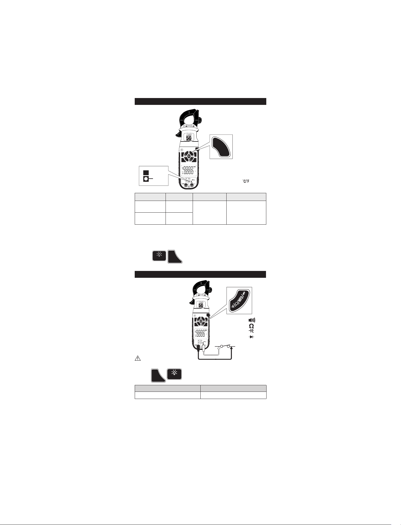
AC/DC Low Amps: <2000µA
CAT III
600V 600A
T
e
A
m
p
RANGE
NCV
/
A
°
μ
F
°
MAX/
MIN
PEAK
DL489
V
H
z
/
D
CATII 1000V
u
t
y
True RMS
T1
30V
T2
CATIII
600V
MAX
C
DC
MFD
Zero
INRUSH
TEMP
• Default = (upper)
• Press x1 = (lower)
• Press x2 = (lower)
µA
µA
• Press and hold = (upper)
WARNING
• Do not attempt to measure more than 2000µA.
Features:
HOLD
Range Resolution Accuracy Overload Protection
600µA 0.1µA
2000µA 1µA
± (1.2% +3 dgts) 600V RMS
True RMS: 45Hz to 400Hz
9
Find Quality Products Online at: sales@GlobalTestSupply.com
www.GlobalTestSupply.com
Page 10
MAX/
MIN
PEAK
Temperature F˚/C˚
T
e
m
p
/
°
F
°
C
MAX/
MIN
PEAK
CAT III
600V 600A
T
e
A
m
p
RANGE
NCV
/
A
°
μ
F
°
C
V
MAX/
H
DC
MFD
z
/
D
MIN
Zero
u
t
y
INRUSH
PEAK
DL489
True RMS
T1
TEMP
30V
T2
TEMP
CATII 1000V
CATIII
600V
MAX
Range Resolution Accuracy Overload Protection
-328˚F to 999˚F
(-200˚ to 999˚C)
1000˚F to 2462˚F
(1000˚ to 1350˚C)
• Disconnect test lead probes from voltage source and meter.
• Move Input Jack Locks to “TEMP” setting.
• Use K-Type thermocouple temperature probes only.
0.1°F (0.1˚C)
1°F (1˚C)
• Stated accuracy does not account for themocople accuaracy.
Features:
HOLD
• Default = T1
• Press x1 = T2
• Press x2 = T1-T2
• Press and hold =
±(1.0% +3.6˚F)
±(1.0% + 2.0˚C)
30V RMS
Continuity
CAT III
600V 600A
T
e
A
m
p
RANGE
NCV
/
A
°
μ
F
°
C
V
MAX/
H
DC
MFD
z
/
D
MIN
Zero
u
t
y
INRUSH
PEAK
DL489
True RMS
T1
30V
T2
TEMP
CATII 1000V
CATIII
600V
MAX
• Buzzer sounds at less than < 40Ω.
WARNING
• Do not measure resistance on a live circuit.
Features:
HOLD
Open Circuit V <1.00V Overload Protection
Threshold Appox. <40Ω 600V RMS
10
• Default =
• Press x1 =
• Press x2 =
• Press x3 =
Find Quality Products Online at: sales@GlobalTestSupply.com
www.GlobalTestSupply.com
Page 11

Resistance: < 60MΩ
RANGE
MAX/
MIN
PEAK
RANGE
MAX/
MIN
PEAK
CAT III
600V 600A
T
e
A
m
p
RANGE
NCV
/
A
°
μ
F
°
C
MAX/
MIN
PEAK
DL489
V
H
z
/
D
u
t
y
True RMS
DC
MFD
Zero
INRUSH
• Default =
• Press x1 =
• Press x2 =
• Press x3 =
Features:
HOLD
T1
30V
T2
TEMP
CATII 1000V
CATIII
600V
MAX
Range Resolution Accuracy Overload Protection
600Ω 0.1Ω
6kΩ 1Ω
60kΩ 10Ω
600kΩ 100Ω
± (0.8% +3 dgts)
600V RMS
6MΩ 1kΩ
60MΩ 0.01MΩ ± (1.2% +3 dgts)
Capacitance (MFD)
CAT III
600V 600A
T
e
A
m
p
RANGE
NCV
/
A
°
μ
F
°
C
V
MAX/
H
DC
MFD
z
MIN
PEAK
DL489
/
D
u
t
y
True RMS
Zero
INRUSH
• Default =
• Press x1 =
• Press x2 =
• Press x3 =
T1
30V
T2
TEMP
CATII 1000V
CATIII
600V
Features:
MAX
HOLD
Range Resolution Accuracy Overload Protection
10.00nF
100.0nF
1.000µF
10.00µF
100.0µF
2000µF
0.01nF
0.1nF
0.001µF
0.01µF
0.1µF
1µF
± (3.0% +5 dgts) 600V RMS
11
Find Quality Products Online at: sales@GlobalTestSupply.com
www.GlobalTestSupply.com
Page 12

GOOD DIODE
MAX/
MIN
PEAK
Reverse Bias
Displays "OL"
Forward Bias
Displays approx.
voltage drop
BAD DIODE
600V 600A
NCV
μ
V
MAX/
H
z
MIN
PEAK
DL489
Diode
CAT III
T
e
A
m
p
/
A
°
F
°
C
MFD
/
D
u
t
y
True RMS
T1
30V
T2
CATII 1000V
CATIII
600V
MAX
• Default =
• Press x1 =
• Press x2 =
• Press x3 =
RANGE
DC
Zero
INRUSH
TEMP
Open Diode
Displays "OL"
or
Both directions
• Forward voltage drop if forward biased.
• “O.L.” if reverse biased.
Features:
HOLD
Diode Test
Range Open Circuit V Test Current Overload Protection
3.0V <3.2V DC 0.25mA 600V RMS
'0' Both directions
Min/Max/Peak
CAT III
600V 600A
T
e
A
m
p
RANGE
NCV
/
A
°
μ
F
°
C
V
MAX/
H
DC
MFD
z
/
D
MIN
Zero
u
t
y
INRUSH
PEAK
DL489
True RMS
T1
30V
T2
TEMP
CATII 1000V
CATIII
600V
MAX
12
Find Quality Products Online at: sales@GlobalTestSupply.com
www.GlobalTestSupply.com
Page 13

RANGE
MAX/
MIN
PEAK
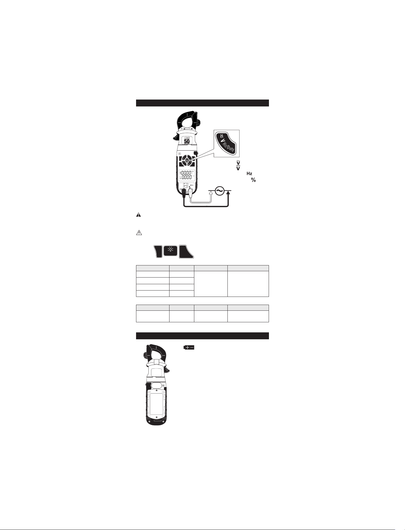
Voltage: AC 750V / DC 1000V
CAT III
600V 600A
High
Voltage
Alert
WARNING
• Use CATIII rated test leads or higher.
• Do not attempt to measure more than 750V AC/1000V DC.
• Keep hands below line when measuring high current levels.
• Do not exceed 25 volts AC or DC – RMS at either the common or
multifunction input ports as measured from earth ground.
• Select AC or DC Voltage.
WARNING
• NCV LED will flash and audible alert over 600V AC/DC
• NCV LED will flash without audible alert over 30V AC/DC
Features:
AC Volts (45Hz to 400Hz)
Range Resolution Accuracy Overload Protection
600mV 0.1mV
6V 1mV
60V 10mV
600V 100mV
750V 1.0V
True RMS: 45Hz to 400Hz
HOLD
T
e
A
m
p
RANGE
NCV
/
A
°
μ
F
°
C
V
MAX/
H
DC
MIN
PEAK
DL489
z
/
D
u
t
y
True RMS
MFD
Zero
INRUSH
• Default =
• Press x1 =
• Press and hold =
• Press and hold x1 =
T1
30V
T2
TEMP
CATII 1000V
CATIII
600V
MAX
± (1.0% +3 dgts) 1000V RMS
DC Volts
Range Resolution Accuracy Overload Protection
600mV 0.1mV
6V 1mV
60V 10mV
± (0.5% +4 dgts)
1000V RMS
600V 1000mV
1000V 1V ±(0.8% +5 dgts)
13
Find Quality Products Online at: sales@GlobalTestSupply.com
www.GlobalTestSupply.com
Page 14
RANGE
MAX/
MIN
PEAK
Frequency (Hz) / Duty Cycle
CAT III
600V 600A
T
e
A
m
p
RANGE
NCV
/
A
°
μ
F
°
C
V
MAX/
H
DC
MFD
z
/
D
MIN
Zero
u
t
y
INRUSH
PEAK
DL489
True RMS
T1
30V
T2
TEMP
CATII 1000V
CATIII
600V
MAX
Use CAT III rated leads or higher.
Press the AC/DC volts button to select AC voltage, press and hold the button
for Frequency and Duty Cycle modes.
WARNING
Do not attempt to measure more than 750V AC/1000V DC.
Features:
HOLD
Frequency
Range Resolution Accuracy Overload Protection
99.99Hz 0.01Hz
999.9Hz 0.1Hz
9.999kHz 1Hz
± (0.1% +3 dgts) 600V RMS
99.99kHz 10Hz
Duty Cycle
Range Resolution Accuracy Overload Protection
1.0 to 99.0% 0.1%
±(0.2% per kHz +
0.1% + 5dgts)
Frequency Sensitivity: 1.8Vrms
• Default =
• Press x1 =
• Press and hold =
• Press and hold x1 =
600V RMS
Battery Replacement
• When the batteries are too low for safe
operation, the Low Battery indicator will display
• Remove the scews from the battery cover.
Remove battery cover.
• Replace the old batteries with 6 new (AAA)
batteries.
• Replace the battery cover.
• Replace the screws.
S/N
14
Find Quality Products Online at: sales@GlobalTestSupply.com
www.GlobalTestSupply.com
Page 15
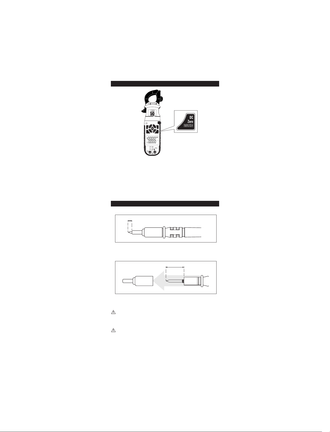
LRA Inrush
4mm
CATIV
600V
CAT III
600V 600A
T
e
A
m
p
RANGE
NCV
/
A
°
μ
F
°
C
V
MAX/
H
DC
MFD
z
/
D
MIN
Zero
u
t
y
INRUSH
PEAK
DL489
True RMS
• Default = DC Zero
T1
30V
T2
TEMP
CATII 1000V
CATIII
600V
MAX
• Press and hold = LRA Inrush
The UEi LRA Inrush is programmed to properly capture the starting current for
compressor motors.
• Select AC Amps.
• Select the range capable of capturing the maximum value.
• Press and hold the DC Zero/ LRA Inrush button – INRUSH will now be shown
on the screen.
• Activate the compressor and read value on the display.
• Press and hold the DC Zero/ LRA Inrush button to return to live readings.
Test Lead Notes
Cat IV and CAT III Measurement Locations
4mm
CATIV
600V
• Ensure the test lead shield is pressed firmly in place. Failure to use the CAT
IV shield increases arc-flash risk.
CAT II Measurement Locations
18mm
CATIV
600V
CATII
1000V
• CAT IV shields may be removed for CAT II locations. This will allow testing
on recessed conductors such as standard wall outlets. Take care not to lose
the shields.
WARNING: Test Lead category protections apply only to test leads and
should not be confused with the meter’s specific CAT rating. Observe the
maximum category protection indicated on the meter the test leads are
plugged into.
CAUTION: If the test leads need to be replaced, you must use a new one
which should meet EN 61010-031 standard, rated CATIII 1000V or better.
15
Find Quality Products Online at: sales@GlobalTestSupply.com
www.GlobalTestSupply.com
 Loading...