

Page 1

C165+
Residential/Commercial Combustion Analyzer
INSTRUCTION MANUAL
ENGLISH
BACKED BY
10
C
o
m
CO/CO2
C165+
b
u
s
t
O2/EFF
AUX
STATUS
LINK
Find Quality Products Online at: sales@GlobalTestSupply.com
www.GlobalTestSupply.com
TEMP/PRS
EXCH TEST
ROOM CO
v3
S
R
P
P
M
E
T
2
O
C
O
C
r
e
z
y
l
a
n
i
A
o
n
8
Page 2

TABLE OF CONTENTS
Functions .............................................2
Features ..............................................2
General Specifications ................................3
Important Safety Warnings ............................3
Symbols ..............................................4
Analyzer Overview ..................................4-5
Overview
Pre Test Checklist
Setting Inlet Temperature
Analyzer Connections
Emptying & Cleaning the In-Line Water Trap
Changing The Particle Filter
Quick Start
Fresh Air Purge
CO Over-range Protection Pump
Measuring Flue Gases
Using The Menu
Combustion Test
- Optional Nitric Oxide Sensor
Heat Exchange Integrity Test
Room CO Test
Printing
Printouts
iOS App Guide
Kane Wireless Printer App Home iOS Screen ............15
Kane Wireless Printer App Settings Screen .............15
Android App Guide
Kane Wireless Printer App iOS Settings Screen ..........16
Kane Wireless Printer App Android Settings Screen ......16
Kane Wireless Printer App Android Personal
Details Screen .....................................16
Temperature Testing
...........................................6
...................................7
...........................7
...............................7
........7
.........................7
..........................................7
......................................8
.....................8
...............................8
..................................9-11
.................................11-12
.....................11
.......................12
......................................12
............................................14
...........................................14
.....................................15
.................................16
...............................17
Temperature/Pressure Testing
Pressure Measurement Good Practice
Large Bore Tubing Issues
Analyzer Specification
Certification
Electromagnetic Compatibility
Where To Test
What Results Are Generally Acceptable
Powering Off
Post Test
General Maintenance
Cold Weather Precautions
Replacing The Batteries
Annual Recertification
Recertification Services
Returning Your Analyzer
Where To Send Your Analyzer
Other Important Factors Relating To Combustion
Combustion Measurement Terms
Disposal
Storage
End Of Life Disposal
Warranty
........................................19
...................................20-21
.......................................22
...........................................22
............................................26
.............................................26
...........................................26
..........................18-19
..............................22
............................23
.............................23
............................24
................................26
.....................17
..............17
...........................17
......................19
............21
..........................22
............................24
......................24
...................25
...25
• Flue temperature: 32° to 1112°F
• Inlet temperature: Internal/ External sensor 32° to 112°F
• O2: 0 - 21%
• CO: 2000 ppm
• CO2: 0 - 20 %
•
EOS Technology
•
Pre-programmed fuels: Nat Gas, H Oil, Pellets, L Oil, LPG,
Butane, Propane, Town Gas, Coke Gas, Bio Gas, Bio Fuel
•
Memory Positions: 45
•
6 line backlit display
FUNCTIONS
• Efficiency: Nett/Gross 99.9%
• Efficiency: High (calculated) 119.9%
• Excess air: 250%
• CO/CO2 ratio: 0.99%
• Differential pressure
FEATURES
•
High altitude compensation
•
User customizable parameter views
•
Individual report printouts
•
Real-time clock
2
Find Quality Products Online at: sales@GlobalTestSupply.com
www.GlobalTestSupply.com
Page 3

GENERAL SPECIFICATIONS
• Operating Temperature: 32° to 112°F (0° to 45°C)
• Storage Temperature: 0° to 120°F (-18° to 50°C)
• Operating Humidity: 10% to 90% R.H.
• Back light: Yes
• Dimensions: 7.87 x 1.77 x 3.5 inch
• Item Weight: 1.375 lbs
IMPORTANT SAFETY WARNINGS
Read entire Safety Notes section regarding potential hazard and proper instructions before using this analyzer. In this manual the
word “WARNING” is used to indicate conditions or actions that may pose physical hazards to the user. The word “CAUTION” is used to
indicate conditions or actions that may damage this instrument.
WARNING
To ensure safe operation and service of the tester, follow these instructions. Failure to observe these warnings can result in severe
injury or death.
WARNING
• Do not use this analyzer during electrical storms or in wet weather.
• To avoid false readings, charge batteries if a low battery indicator appears.
• Always adhere to national and local safety codes. Use proper personal protective equipment (PPE)
• Calibration: Recommended Annually
• Certification: CE Conformity, RoHS, REACH Compliant,
AHRI 1260 standard, FCC
• Battery Size: Alkaline or NiMH AA 3
• Accuracy: ± (% of reading + # of least significant digits)
WARNING
This analyzer extracts combustion gases that may be toxic in relatively low concentrations. These gases are exhausted from the back
of the analyzer.
This analyzer must only be used in well-ventilated locations by trained and competent persons after due consideration of all
potential hazards.
Users of portable gas detectors are recommended to conduct a “bump” check before relying on the unit to verify an atmosphere is free
from hazard. A ‘bump” test is a means of verifying that an instrument is working within acceptable limits by briefly exposing to a known
gas mixture formulated to change the output of all the sensors present.
NOTE: This is different from a calibration where the instrument is also exposed to a known gas mixture but is allowed to settle to a
steady figure and the reading adjusted to the stated gas concentration of the gas of the test gas.
3
Find Quality Products Online at: sales@GlobalTestSupply.com
www.GlobalTestSupply.com
Page 4

SYMBOLS
LINK
Low Battery Degrees Fahrenheit
Degrees Celsius Menu
LINK Pump Off & Pump On
Pump Start Pump Stop
Navigate Down Navigate Up
Enter Key Wireless/Store/Print
ANALYZER OVERVIEW
A. Infrared Printer Port
B. On/ Off (Power) Button
C. 6 Line Backlit Display
• Press any button to turn Back light on.
D. Pump Toggle Button: short press is data hold, long press turns pump on and off
E. UP Button
• Short press to navigate “UP”
F. Wireless/Store/Print Button: short press print, long press store
G. Down Button:
• Short press to navigate “DOWN”
H. ENTER Button: short press works as enter, long press turns on work light
I. Rotary Dial
J. Particle Filter (inside water trap)
K. Water Trap
L. LED Water Trap Indication
M. Protective Rubber Boot with Magnets
N. Serial Number QR Code: (Serial Number viewable under Protective Boot)
O. Sensors Fitted: (label under Protective Boot) Sensors that can be fitted in unit when shipped (CO-H2, CO, CO2, NO, O2)
P. Battery Compartment: (under Protective Boot)
Q. Grip Indentation: Indentation for fingers to grip analyzer
R. Water Trap Drain Plug (Red plug; take caution NOT to damage plug when removing protective boot)
S. Battery Charge USB Adapter Connection
T. Temperature Connections
• Flue Probe Temperature: T1
• Inlet Temperature: T2
U. Flue Gas Inlet Connection
V. Pressure Connections
• Pressure: P1
• Differential Pressure: P2
W. Infrared Printer Port
4
Find Quality Products Online at: sales@GlobalTestSupply.com
www.GlobalTestSupply.com
Page 5

C
o
m
b
u
s
t
i
o
n
A
n
a
l
y
z
e
r
C165+
C
O
C
O
2
T
E
M
P
P
R
S
STATUS
LINK
v3
AUX
O2/EFF
CO/CO2
TEMP/PRS
EXCH TEST
ROOM CO
ANALYZER OVERVIEW (CONT.)
A
B
C
N
UEi TEST INSTRUMENTS
www.ueitest.com
Tel: 1-800-547-5740
Serial No.
D
E
F
G
H
I
J
K
L
M
CO-H
CO
O
Sensors
2
Fitted:
CO
NO
2
O
2
P
Q
R
S
T
Narrow Pin MUST be on the
T2
P2
T1
P1
Right hand side.
U
V
Flue Probe Temperature Plug
(Plugs into T1)
Red Connector
(plugs into Flue
Gas Inlet)
[BOTTOM]
Flue Probe
Gas Inlet Plug
W
[TOP]
5
Find Quality Products Online at: sales@GlobalTestSupply.com
www.GlobalTestSupply.com
Page 6

OVERVIEW
The C165+ Combustion Analyzer measures CO, CO2, differential temperature and differential pressure.
CO2 is set to zero in fresh air automatically after the initial countdown.
It is important that re-zeroing is done in outside fresh air as indoor CO2 levels are affected by human breath.
It calculates oxygen (O2), CO/CO2 ratio, Losses, Combustion Efficiency (Gross, Nett, Gross Condensing, or Nett Condensing).
The C165+ Combustion Analyzer can also measure CO levels in ambient air - useful when a CO Alarm is triggered. It can also perform a Room CO Test
for 30 minute duration.
A low flow detection system warns of low flow and switches the pump off. This also helps to prevent water ingress from overfilled water traps.
The analyzer has a protective rubber boot with magnets for hands-free operation and is supplied with a probe with an integral temperature sensor.
A large 6 line display provides the user with relevant information. All data can be printed via the infrared printer or Wireless Printer App.
The C165+ uses a new data storage system allowing the user to store the maximum number of logs of interest to them, rather than be restricted to
an allowance of particular logs.
The memory can store up to 45 logs of any combination of Combustion, AUX, Temperature, Heat Exchange, Room CO.
6
Find Quality Products Online at: sales@GlobalTestSupply.com
www.GlobalTestSupply.com
Page 7

PRE TEST CHECKLIST
T2
T1
P2
P1
• Clean particle filter
• Water trap and probe line are empty of water
• Power on and zero
• All hose and thermocouple connections are properly secured
• Flue gas probe is sampling ambient FRESH air
• Water trap is fitted correctly to the instrument
• Flue temperature plug is connected
• Ensure water trap plug is inserted correctly
SETTING INLET TEMPERATURE
• Turn on and zero the analyzer, without the flue probe connected, to use ambient temperature
• Connect the flue probe thermocouple to T1 during zero countdown use for inlet ducted system
• Connect a thermocouple to T2 to measure second temp source
ANALYZER CONNECTIONS
WARNING
Turning the pump off while the probe is in the flue will leave toxic gases inside the analyzer. Once
data has been printed or copied, it is advisable to purge the unit with fresh air as soon as possible.
To do this remove the probe from the flue and turn ON pump. Always allow the readings to return to
zero (20.9% for O2) prior to shutting the unit off. The meter will not switch off until the CO reading is
below 20 ppm.
CAUTION
The probe will be hot from flue gases. Remove the probe from the flue and allow it to cool naturally.
Do not immerse the probe in water, as this will be drawn into the analyzer and damage the flue
probe and the pump and sensors.
NOTE: Take care when
inserting the temperature
probes as the pins are
polarized. Insert with the
smaller pin (+) to the right.
EMPTYING & CLEANING THE IN-LINE WATER TRAP
• Remove the rubber plug
• Allow the water to drain out
• Re-insert the rubber plug
CHANGING THE PARTICLE FILTER
• Remove the protective rubber boot
• Slide the water trap unit from the analyzer
• Remove the particle filter from its’ spigot and replace
• Slide the water trap back into position and replace the protective rubber boot
QUICK START
Turn on the analyzer by pressing the On/Off Button for 2 seconds until the unit activates. As described the analyzer will perform a 60
second turn on purge. Once completed simply select the reading desired by the position of the rotary dial.
7
Find Quality Products Online at: sales@GlobalTestSupply.com
www.GlobalTestSupply.com
Page 8

FRESH AIR PURGE
NOTE
Each time the analyzer is turned on it will perform a 60 second air purge, this is to clear the gas
sampling path (including probe, if connected). For these reasons it is very important that the analyzer
be in outside fresh air when powered on.
CO OVER-RANGE PROTECTION PUMP
The analyzer’s intelligent protection system will automatically activate the protection pump once an over-gas condition is detected
(see specification table for detection limits). When activated the main sampling pump will be shut down, allowing the sample system
to be purged with fresh air. Once readings have returned to a safe level, the protection pump will shut down and the main pump will
reactivate.
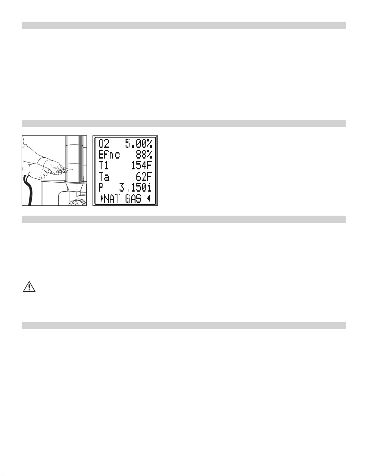
MEASURING FLUE GASES
After the initial countdown is finished and the analyzer is properly setup, put its’ flue probe in the appliance’s sampling point. The tip of
the probe should be at the center of the flue. Use the flue probes depth stop cone to set the position.
With balanced flues, make sure the probe is positioned into the flue so no air can “back flush” into the probe.
CAUTION!: Ensure the flue probe handle does not get hot!
Boiler
Flue
20”
8
Find Quality Products Online at: sales@GlobalTestSupply.com
www.GlobalTestSupply.com
Page 9
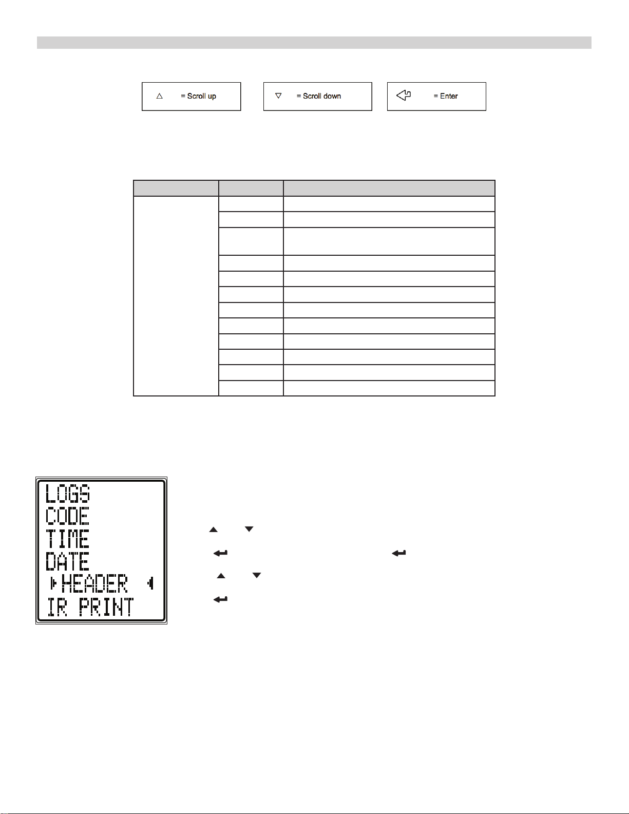
USING THE MENU
Select “Menu” on the rotary switch and navigate using the function buttons:
NOTE: To “EXIT” the “MENU” at any time simply move the rotary switch to any position other than “Menu”. Any changes that have not been
“entered” will be ignored.
MENU SCREEN
MENU OPTIONS/COMMENTS
LOGS VIEW, EXIT, DELETE ALL
CODE 000000 (PASSWORD PROTECTED FOR AUTHORIZED
SERVICE PERSONAL ONLY
TIME HH:MM:SS
DATE MM:DD:YY
HEADER LINE 1, LINE 2, BACK
IR PRINT KMIRP, IRP-2/3
˚C/˚F ˚C or ˚F
GAS UNIT ppm, mg/kWh, mmg/m3
LANGUAGE ENGLISH, FRANCAIS, ESPANOL
EFF GROSS, NETT
O2 REF CO %
The Menu position on the Rotary Dial allows for the customization of the default settings for the analyzer as per the user’s
requirements. Navigation through the Menu system is via the dedicated user’s interface buttons (Up, Down, Enter).
As you navigate up or down through the Menu, the items will scroll accordingly, eventually back to the beginning.
Rotate Selector Dial to MENU to set up or customize your settings.
Selected parameter are centered, highlighted with arrow icons on either side.
Use
Press to a select a parameter to edit. Press button to scroll fields to change.
Press and buttons to change field contents.
Press to enter content selected.
The analyzer will perform a 60 second purge in Rotary Dial setting of AUX, O2/Eff, CO/CO2. This should be done in fresh air.
and buttons to scroll menu options.
9
Find Quality Products Online at: sales@GlobalTestSupply.com
www.GlobalTestSupply.com
Page 10

COMBUSTION TESTS
Insert the tip of the flue probe into the center of the flue. The readings will stabilize within 60 seconds assuming the system conditions are stable.
The rotary switch can be used to display the following information:
O2/Eff
Fuel type can be changed via “STATUS” setting.
Carbon Dioxide (%)
Oxygen (%) left after combustion. Should be 20.9% ± 0.3% in fresh air.
Gross efficiency
Flue temperature (°F).
Inlet temperature (°F). Normally set by flue probe during fresh air purge.
Press to print a full combustion test, (or send to Smart Device via optional Wireless module).
Hold
CO/CO2
Fuel type can be changed via “STATUS” setting.
Carbon monoxide (ppm).
COa is CO ambient
Losses calculated
Excess air %
Pressure reading
Press
Hold
AUX display
The AUX (auxiliary) display can be customized via “MENU” / “SCREEN” / “AUX”.
The parameters displayed on lines 1, 2, 3, 4 and 5 can be set by the user.
They remain the AUX parameters until changed by the user.
Press to print a full combustion test, (or send to Smart Device via optional Wireless module).
Hold for 2+ seconds to log a full combustion report.
for 2+ seconds to log a full combustion report.
to print a full combustion test, (or send to Smart Device via optional Wireless module).
for 2+ seconds to log a full combustion report.
10
Find Quality Products Online at: sales@GlobalTestSupply.com
www.GlobalTestSupply.com
Page 11

COMBUSTION TEST - OPTIONAL NITRIC OXIDE SENSOR
Instructions for C165+ Analyzers fitted with optional Nitric Oxide (NO) sensors
Displaying the Nitric Oxide (NO) reading
Select “Menu” on the rotary switch and navigate using the function buttons:
Select SCREEN and then select AUX
Choose a line to display the required readings as below
AUX display
The AUX (auxiliary) display can be customized via MENU / SCREEN / AUX.
The parameters displayed on lines 1, 2, 3, 4, 5 and 6 can be set by the user.
They remain the AUX parameters until changed by the user.
NOTE: To EXIT the MENU at any time simply move the rotary switch to any position other than MENU.
Any changes that have not been “entered” will be ignored.
Use and to navigate to the main menu option SCREEN Press .
Use and to navigate to the sub menu option AUX Press .
PRINTING and STORING
The NO readings are printed and stored in the same way as the other combustion gas readings. On the
printouts the NO readings appear directly below the flue CO readings or AUX
The dial needs to be in O2/Eff, CO/CO2 or AUX position to print or store. When the dilution pump is operating to protect the CO sensor the NO readings are also affected by an unspecified amount. The screen
typically will show: ----
11
Find Quality Products Online at: sales@GlobalTestSupply.com
www.GlobalTestSupply.com
Page 12

HEAT EXCHANGE INTEGRITY TEST
There are many methods to test heat exchange integrity. One of these is to observe the Excess Air, O2 and CO readings both before and
after the blower turns on. If the heat exchanger is sealed, your O2 and CO readings should remain fairly stable. A breach in the heat
exchanger may allow fresh air to be forced into the flue after the blower turns on due to pressure increase in the plenum. The result
may be a rise in the measured O2 in the stack gas and an increase in Excess Air. In some sealed systems the fresh air drawn in through
the breach may reduce the combustion air available leading to an increase in the CO reading. If either of these situations are present it
is probable there is a problem with the Heat Exchanger which may require additional testing and inspections.
NOTE: Many cracks are invisible to borescopes or the naked eye, and only open or separate from pressure or temperature changes
during operations. Rotate dial to “EXCH TEST” Rotate test selector to “EXCH TEST”. Call for heat on the system. Observe and wait for
O2 readings to stabilize.
No probes or hose connections are required for this test.
Rotate selector dial to Room CO
Press Enter Button to select GENERAL test type
CO readings will be logged every minute for 30 minutes.
Readings will be saved once the 30 minute test is completed.
Test results and LOG number will be displayed.
Press Print Button to Print the test results.
This LOG will be saved in the LOGS/ROOM CO MENU screen.
ROOM CO TEST
12
Find Quality Products Online at: sales@GlobalTestSupply.com
www.GlobalTestSupply.com
Page 13

PRINTING
Rotate selector Dial to Menu Position.
Use or Arrow Buttons to select Printer.
Press button.
Use or Arrow Buttons to select Printer type (KMIRP, IRP-2/3)
Wireless Printer App
Please see pages 15 and 16
To Go to LINK setting on Rotary Dial
Use Up or Down arrows
Select App to print
[IRP2] [KMIRP2]
PRINTOUTS
O2/Eff CO/CO2 AUX PRS/TEMP HEAT EXCHANGE
07/15/21
07/15/21
07/15/21 07/15/21
07/15/21
13
Find Quality Products Online at: sales@GlobalTestSupply.com
www.GlobalTestSupply.com
Page 14

WPC2 DTHA2
PRINTOUTS (CONT.)
07/15/21
07/15/21
14
Find Quality Products Online at: sales@GlobalTestSupply.com
www.GlobalTestSupply.com
Page 15

Printer
12:00 PM
100%
12:00 PM
100%
ANALYSER TYPE
Select the analyser model you’re
connecting to.
Select Analyser
TEXT CAPTURE STYLE
Select what test processing style
you’d like to use.
YOUR NAME
Provide your name to use for
correspondence from the App...
Your Name
YOUR COMPANY NAME
Provide your Company name for
correspondence from the App...
Your Company
Printer
Settings
Print out
Connect to Analyser
iOS APP GUIDE
Install the App
• Free download from Apple® App store
• Search for “Kane Wireless Printer” and install
Upon opening App the first time, it will ask you a series of questions:
• Allow access to device location (GPS)
• Allow access to contacts (for emailing)
Kane Wireless Printer App Home iOS Screen
Pairing the Kane Wireless Printer app with your Analyzer
Turn on your analyzer allowing a complete startup
In the App Press PRINTOUT
Select CONNECT TO ANALYZER
• Your Analyzer’s serial number, proceeded by a “K”, should appear
• Select your analyzer to pair
Kane Wireless Printer App Settings Screen
Print to App from Analyzer
• When testing in the AUX, O2/Eff, CO/CO2, PRS/TEMP, HEAT EXCH screen
• Press FILE (Wireless) Button to enter print menu
• Scroll ARROW Button to select Wireless
• Press Button to print to App
To Disconnect an analyzer
• Select disconnect from Printout screen
Adding Notes & Emailing from the Kane Wireless Printer App
In PRINTOUT screen, Select EMAIL PRINTOUT
• A message window will open
• Enter email address
• Add message/notes to Printout
• Send message
Select CLEAR CONSOLE to delete a Printout
• Press to Confirm deletion
To print Saved LOGS from Analyzer to App
To print Saved LOGS from Analyzer to App
• Rotate Selector dial to MENU
• Press or Arrow Buttons to select LOGS. Press Button
• In the LOGS screen. Press Button to VIEW.
• Press or Arrow Buttons to select LOGS VIEW you want. Press Button
Email Printout
Clear Console
Find Quality Products Online at: sales@GlobalTestSupply.com
15
www.GlobalTestSupply.com
Page 16

24%
12:00 Provider
KANE Wireless Printer
24%
12:00 Provider
24%
12:00 Provider
Connected to AUTOplus 051717..
AUTOplus V1 . 08
SERIAL No. 051717568
YOUR COMPANY NAME &
PHONE NUMBER HERE
DATE
TIME
Enable NightMode function
11/04/18
09:19:52
SW No.: 19086
SW ver: 1.4.5
ANDROID APP GUIDE
Installing the App
• Free download from Google Play
• Search for “Kane Wireless Printer” and install
Upon opening App the first time, it will ask you a series of questions:
• Allow access to device location (GPS)
• Allow access to contacts (for emailing)
Kane Wireless Printer App Home Android Screen
Start up
• Press the Menu icon in top left of screen
• Press Settings
A. Select “Your Name”, enter name and Press “OK”
B. Select “Your Company Name”, enter name and Press “OK”
C. Select “Analyser Type” select “Other Kane Analyser”
Kane Wireless Printer App Android Settings Screen
Pairing the Kane Wireless Printer app with your Analyzer
• Turn on your analyzer and allow it to complete its startup
• Touch the Kane Wireless Printer banner of the home page
• From the “Pick a device” screen, touch “Scan For Devices” at the bottom of the page
• Your Analyzer’s serial number, proceeded by a “K”, appears of the list. Select it to pair
Settings
Help
Feedback
Share this app
Visit Kane
on YouTube
on Twitter
on Facebook
Personal Details
Your Name
Provide your name to automatically use in correspondence
Your Company Name
Provide your company name to automatically use in
correspondence
Application Settings
Analyser Type
Select the analyser model you’re connecting to
Printout Font Scaling
Change the font scale so your printout fits better on-screen
Print to App from Analyzer
• When testing in AUX, O2/Eff, CO/CO2, PRS/TEMP, HEAT EXCH screen
• Press FILE (Wireless) Button to enter print menu
• Scroll Arrow Button to select Wireless
• Press Button to print to App
To Disconnect an analyzer
• Select disconnect from Printout screen
Adding Notes & Emailing from the Kane Wireless Printer App
-After a report is on the app, Press the Pen icon on the top right of the app screen.
• Press “Write your note here” and you can type your notes for the report. Press “OK”
icon when done and it will save the note under the report.
• Press the “3 vertical dots” icon on the right side of the screen
• From that drop-down menu, Press “Email” icon
• Find and select your email app from the list. The email app will open to a new message and
your report will be attached
Kane Wireless Printer App Android Personal Details Screen
To print Saved LOGS from Analyzer to App
• Rotate Selector dial to MENU
• Press or Arrow Buttons to select LOGS. Press Button
• In the LOGS screen. Press Button to VIEW.
• Press or Arrow Buttons to select LOGS VIEW you want. Press Button
GPS Tagging
Tag printouts with gps location
16
Find Quality Products Online at: sales@GlobalTestSupply.com
www.GlobalTestSupply.com
Page 17

PRESSURE/TEMPERATURE TESTING
Select the Temperature Rotary Dial position.
Use the T1 connection for the Flue Probe temperature sensor
Use the T2 connection for the Inlet temperature sensor
Real time temperature difference
Real time pressure reading
WARNING
NEVER ATTEMPT TO TAKE A PRESSURE READING WITHOUT KNOWING THE MAXIMUM PRESSURE THAT MIGHT BE PRESENT. THIS
INSTRUMENT’S PRESSURE TRANSDUCER IS RATED AT 1.1 PSI WITH A MAXIMUM OVER RANGE OF 5.8 PSI.
Select “TEMP/PRS”. The pump stops automatically. Using the black connectors and manometer hose, connect to P1 for single
pressure or P1 and P2 for differential pressure.
Pressure units can be selected via “MENU”.
Eg Flow Temp
Eg Return Temp
Differential Temp
Press
Hold
WARNING
Before using the UEi C165+ to measure the pressure of a gas/air ratio valve, read the manufacturer’s manual thoroughly. If in doubt,
contact the manufuctuer.
After adjusting a gas/air ratio valve, it is essential the CO, CO2 are within the manufacturer’s specified limits.
If using larger bore tubing when performing pressure tests:
Push tubing over the rim of the This may not produce a gas tight seal.
spigot to ensure a gas tight seal.
to print a full pressure test, (or send to Smart Device via optional Wireless module).
for 2+ seconds to log a pressure report.
PRESSURE MEASUREMENT GOOD PRACTICE
LARGE BORE TUBING ISSUES
Connecting WPC2 or DTHA2 to FGA
Select Menu option with Rotary Dial in LINK position
Options are APP or LINK
In LINK option
Press ENTER button to select choice
ADD, REMOVE, STATUS, BACK use Up or Down arrow button to
select option
Select a device (WPC2, DTHA2) use Up or Down arrow button to
select device
Enter WPC2 or DTHA2 serial number
Serial Number if more than 10
digits, use only last 10 digits
Serial Number if less than 10
digits add 000 (i.e., 0002001228)
All WPC2 serial number start
with 01AF2
NOTE: WPC2 will require
adding serial number for each
clamp
Find Quality Products Online at: sales@GlobalTestSupply.com
www.GlobalTestSupply.com
17
Page 18

ANALYZER SPECIFICATIONS
PARAMETER RANGE RESOLUTION ACCURACY
Temp Measurement
Flue Temperature
Inlet Temperature
(Internal sensor)
Inlet Temperature
(External sensor)
Flue Gas Measurement
2
*
Oxygen
Carbon monoxide
Carbon dioxide
Efficiency (Net or Gross)
Efficiency High (C)
Excess Air
*
CO/CO2 ratio
1
*
1
*
2
2
*
2
*
2
*
32°-1112°F
32°-122°F
32°-1112°F
0-21%
0 to 2000ppm
2000 to 9999ppm
Above 9999ppm
Purge pump
operates
0-20%
0-99.9%
0-119.9%
0-250%
0-0.999
0.1°F
0.1°F
0.1°F
0.1%
1ppm
0.1%
0.1%
0.1%
0.1%
0.0001
±3.6°F
±0.3% reading
±3.6°F
±0.3% reading
±3.6°F
±0.3% reading
±0.3%
±3ppm or ±5% of rdg
±10% of rdg
unspecified
±0.3% volume
±1.0% reading
±1.0% reading
±0.2% reading
±5% reading
Nitric Oxide Sensor
0 to 100ppm
1ppm + 2ppm <30ppm
(optional)
Overrange to 1500ppm
Pressure (differential)
±80mbar 0.1mbar ±0.5% FSD
Pre-programmed Fuels NAT GAS, H OIL, PELLLETS,OIL, LPG, BUTANE, PROPANE
User programmed Fuels 5 user defined fuels
Storage Capacity 45 Total Tests
*1 Using dry gases at STP
*2 Calculated
1
*
1
+5ppm <100ppm
*
+5% reading >100ppm
18
Find Quality Products Online at: sales@GlobalTestSupply.com
www.GlobalTestSupply.com
Page 19

ANALYZER SPECIFICATIONS CONT.
Carbon Dioxide resolution is 0.01% below 1% measured value.
Ambient Operating Range 32° to 113°F (0° to 45°C) 10% to 90% RH
Storage Temperature Range 0° to 120°F (-18° to 50°C)
Battery Type / Life 3 AA cells
>8 hours using Alkaline AA cells
Chargers (optional) 100-240v charger, for NiMH batteries only
Dimensions
Probe: 7.87 x 1.77 x 3.5 in (200 x 45 x 90mm)
11.8 in (300mm) long including handle.
2.3 dia. x 9.4 in (6mm dia. x 240mm) long stainless-steel shaft with 6.5ft
(2m) long neoprene hose. Type K thermocouple
CO Protection Pump: Operates at 2000ppm measured CO.
The C165+ is in conformity with the relevant Union harmonization legislation listed below:
Directive Title
201430EU Electromagnectic Capability
201165EU Restriction of use of certain hazardous substances in electrical
and electronic equipment (RoHS)
The following harmonized standards and technical specifications have been applied:
CERTIFICATION
The UEi C165+ is TUV-tested and certified to EN 50379, Parts 1, 2 & 3 in accordance to 1st German Federal Emission Control Ordinance
(BlmSchV)
EMC
EN507270:2015
Safety
EN61010-1:2010
RoHS
IEC62321-2:2013, IEC62321-1:2013; IEC62321-3-1;2013, IEC63321-5:2013, IEC623321-4:2013, IEC62321-7-2:2017, IEC62321-7-1:2015,
IEC62321-6:2015, AHRI 1260
FCC
ELECTROMAGNETIC COMPATIBILITY
European Council Directive 89/336/EEC requires electronic equipment not to generate electromagnetic disturbances exceeding defined levels and
have adequate immunity levels for normal operation. Specific standards applicable to this analyzer are stated below.
As there are electrical products in use pre-dating this Directive, they may emit excess electromagnetic radiation levels and, occasionally, it may be
appropriate to check the analyzer before use by:
Use the normal start up sequence in the location where the analyzer will be used.
Switch on all localized electrical equipment capable of causing interference.
Check all readings are as expected. A level of disturbance is acceptable.
If not acceptable, adjust the analyzer’s position to minimize interference or switch off, if possible, the offending equipment during your test.
At the time of writing this manual (November 2020) UEi Test Instruments is not aware of any field-based situation where such interference has
occurred, and this advice is only given to satisfy the requirements of the Directive. This product has been tested for compliance with the following
generic standards and is certified to be compliant.
EN 61000-6-3 : 2011
EN 61000-6-1 : 2007
Specification EC/EMC/KI/C165+ details the specific test configuration, performance and conditions of use.
19
Find Quality Products Online at: sales@GlobalTestSupply.com
www.GlobalTestSupply.com
Page 20

WHERE TO TEST
Air Conditioning / Heat Pump
Suction Line:
• Temperature
Verify proper:
• Static Duct Pressures
• Temperature Differential
• Static Pressure Drop Across Coils
to condensing unit
Boiler & Water Heaters & High Efficiency Modulating Hot Water Systems
Boiler
Verify proper combustion:
• O
• CO2
• CO Air Free
• Stack Temp
• Stack Draft
2
Water Heater
Draft
Verify proper combustion:
• O
• CO2
• CO
• Stack Temp
• Efficiency
2
HE Boiler Instant Water
Heaters
Draft
Verify proper
combustion:
• O
• CO2
• CO
• Stack Temp
• Efficiency
Hi / Low fire
Gas Pressure
Supply and Return Water temp
2
Furnaces: 80% Furnaces: 90%
80% Furnace
Verify proper combustion:
• O
• CO2
• CO
• Stack Temp
• Vent Pressure
• Efficiency
2
90%+ Furnace
Verify proper combustion:
• O
2
• CO2
• CO
• Stack Temp
• Vent Pressure
• Efficiency
Verify/Set Up
• Gas Pressure
Test
• Limit Switch
• Pressure Switch
Verify proper operation:
• Static Duct Pressure
• Temperature Rise
• AC side Static Pressure
Drop across coils
20
Find Quality Products Online at: sales@GlobalTestSupply.com
www.GlobalTestSupply.com
Verify/Set Up
• Gas Pressure
Test
• Limit Switch
• Pressure Switch
Verify proper operation:
• Static Duct Pressure
• Temperature Rise
• AC side Static Pressure
Drop across coils
Page 21

WHERE TO TEST (CONT.)
Furnaces (continued): Atmospheric, Gas & Oil
Atmospheric Furnace
Draft
Verify proper
• Temperature Rise
• AC side Static Pressure
Drop across coils
Verify proper combustion:
• O
• CO2
• CO
• Stack Temp
• Efficiency
2
Oil Furnace
Verify proper combustion:
• O
• CO2
• CO
• Stack Temp
• Stack Draft
• Efficiency
2
Natural Gas & Propane
Verify proper combustion:
• O
• CO2
• CO
• Stack Temp
• Vent Pressure
• Efficiency
Test
• Limit Switch
• Pressure Switch
Set Up
• Gas Pressure
Verify proper:
• Static Duct Pressure
• Temperature Rise
• AC side Static Pressure
Drop across coils
2
Test & Verify:
• Smoke
Set Up
• Over Fire Draft
Verify proper
• Static Duct Pressure
• Temperature Rise
• AC side Static Pressure
Drop across coils
WHAT RESULTS ARE GENERALLY ACCEPTABLE
Atmospheric Gas
Fixed Burners
Gas Fired Burners Oil Fired burners
(#2 Oil Fuel)
Positive Overfire Gas
& Oil
Oxygen 7 to 9% O2 3 to 6% O2 4 to 7% O2 3 to 9% O2
Stack temperature 325˚ to 500˚F 275˚ to 500˚F 325˚ to 600˚F
Draft (Water Column Inches) -.02 to -0.4 InWC -.02 to -0.4 InWC -.04 to - 0.6 InWC -.02 to -0.4 InWC
Carbon Monoxide (parts per million) <100 ppm <100 ppm <100 ppm <100 ppm
Overfire Draft (Water Column Inches) -.02 InWC -0.2 InWC 0.4 to 0.6 InWC
Smoke 0 (manufacturer's
recommendation)
NOTE: Follow manufacturer guidelines for the specific equipment being serviced
Typical Excess Air Levels
O2% (measured) Excess Air %
Natural Gas 3% 16.7%
LIGHT Oil 5% 31%
Coal 8% 62%
21
Find Quality Products Online at: sales@GlobalTestSupply.com
www.GlobalTestSupply.com
Page 22
POWERING OFF
When you power off the C165+, there is a 45 second purge when in O2/Eff, CO, CO2, AUX screens.
Make sure you do not exceed the analyzer’s operating specifications. In particular:
• Do not exceed the flue probes maximum temperature (1112˚F)
• Do not exceed the analyzer’s internal temperature range
• Do not put the analyzer on a hot surface
• Do not exceed the water trap’s level
• Do not let the particle filter become dirty and blocked
View the displayed data to ensure that the stable operating conditions have been achieved and the readings are within the expected
range.
POST TEST
Remove the probe from the flue and allow analyzer to purge with fresh air
until readings return to zero. O2 to 20.9%, CO to Zero (Be careful the probe
tip will be HOT).
GENERAL MAINTENANCE
• Re-certify your instrument annually to ensure it meets original performance specification
• Keep your instrument dry, if it gets wet, wipe dry immediately. Liquids can degrade electronic circuits
• Whenever practical, keep the instrument away dust and dirt that cause premature wear
• Although your instrument is built to withstand the rigors of daily use, it can be damaged by severe impacts.
• Use reasonable caution when using and storing this meter
PERIODIC SERVICE
WARNING
Repair and service of this instrument is to be performed by qualified personnel only. Improper repair or service could result in physical
degradation of the instrument. This could alter the protection from personal injury this meter provides to the operator. Perform only those
maintenance tasks that you are qualified to do.
It is important you keep your flue gas analyzer in a warm and dry place overnight
Electronic devices that become really cold, by being left in a vehicle overnight, suffer when taken into a warm room the next
morning. Condensation may form which can affect the analyzer’s performance & cause permanent damage. See operating and storage
temperature specifications.
Electrochemical sensors used in flue gas analyzers can be affected by condensation or water being sucked into the analyzer, as the
small apertures on top of sensors can become blocked with water, stopping sensors seeing flue gas. When this happens, oxygen or
carbon dioxide reading will display as “—” & sensors may be permanently damaged
COLD WEATHER PRECAUTIONS
If you think that your analyzer is affected by condensation or water ingress, it may be possible to rectify the problem yourself. Simply
leave the analyzer running in a warm place, with the pump ‘ON’ sampling fresh air for a few hours (use mains adapter/battery charger if
needed). If, after doing this, you still experience problems please contact our Service Center.
22
Find Quality Products Online at: sales@GlobalTestSupply.com
www.GlobalTestSupply.com
Page 23

REPLACING THE BATTERIES
This meter has been designed for use with both Alkaline or rechargeable Nickel Metal Hydride (NiMH) batteries. No other types are
recommended and will void warranty. The analyzer is supplied with 3 (AA) size NiMH rechargeable batteries. These should be installed
into the instrument.
CAUTION
Take great care when installing the batteries to observe correct polarity. Always check the meter
for operation immediately after installing new batteries.
Using Rechargeable Batteries
The battery charger must only be used when NiMH batteries are fitted. Alkaline batteries are not rechargeable. Attempting to recharge
alkaline batteries may result in damage to the product and create a fire risk.
When changing the batteries, the time and date will need setting.
WARNING
Do not try and charge the unit with Alkaline batteries fitted. Do not mix NiMH cells of different capacities from different
manufacturers, all cells must be identical.
Turn over the analyzer, remove the protective rubber boot and fit 3 “AA” batteries in the battery compartment. Take great care to
ensure they are fitted with the correct battery polarity. Replace the battery cover and the protective rubber boot.
Time and Date
When changing the batteries, the time and date will need setting.
Battery Disposal
Always dispose of depleted batteries using approved disposal methods that protect the environment.
Battery Charging
Ensure that you use the correct charger. This unit uses a 5V regulated charger. Ensure the batteries are fitted in the correct manner,
and charge for at least 16 hours. Subsequent charges should be overnight. NiMH batteries may be charged at any time, even for short
periods to conduct testing.
WARNING
Under NO circumstances should you expose batteries to extreme heat or fire as they may explode and cause injury. Always dispose of
old batteries promptly in a manner consistent with local disposal regulations.
CANADIAN ANNUAL RECERTIFICATION SERVICES
KANE CANADA MEASUREMENT SOLUTIONS
All Canadian customers needing annual recertification services should...
23
Find Quality Products Online at: sales@GlobalTestSupply.com
www.GlobalTestSupply.com
Page 24

BACKED BY
10
8
USA ANNUAL RECERTIFICATION SERVICES
Complete care for your C160 series combustion analyzer.
When you:
Request Recertification or Service Online
Within 1 Year of Purchase or Last Service
UEi will:
10 Year Warranty: All UEi combustion analyzers have a standard 1-year
warranty. Each recertification extends the warranty for 1 more year for up to 10
years from the date of purchase.
Contractors who book recertification of a C160 series analyzer at
within 12 months from either the date of
purchase or the date of the last recertification will receive reduced
service pricing that lowers the cost of ownership and 2 additional
benefits:
Same Day Service: All qualifying analyzers received for recertification through
UEi Service+ are returned on the same business day.*
*Analyzers that include the additional NO (Nitric Oxide) sensor requires 48-hour turnaround.
PRODUCT REGISTRATION
Register Online
Registering you analyzer online is quick and easy. Just log in or setup an account, it only takes a couple of minutes. Once logged in you
can register you analyzer by providing some product information and uploading a proof-of-purchase.
When it’s time to request recertifcation, just log into your account, select the analyzer, select the service and place your order.
24
Find Quality Products Online at: sales@GlobalTestSupply.com
www.GlobalTestSupply.com
Page 25

OTHER IMPORTANT FACTORS RELATING TO COMBUSTION
The three T’s of combustion
• Time: Amount of time that the fuel and oxygen are together in the combustion chamber
• Temperature: How high the temperature is determines the rate of oxidation, or spread of combustion
• Turbulence: How well the fuel and air are mixed
These three factors are all interrelated and will move your results along the combustion curves.
COMBUSTION MEASUREMENT TERMS
Other parameters measured include Net temperature, draft and efficiency.
Net Temperature
Net temperature is the difference between the combustion air entering the combustion chamber and the flue gas temperature past
the heat exchange. This is used to determine how efficient the system is extracting heat from the combustion process in addition to
the performance of the combustion process. On sealed systems that have ducted inlet air for combustion air, the Net temperature
must compare this air stream temperature with the flue gases. If the appliance simply uses room air for the combustion air, our
analyzers have an internal temperature sensor, so it will use this temperature when calculating Net temperature. The most accurate
results for efficiency are obtained when measuring flue gases at the point where flue temperature (not flame temperature) is the highest.
Draft
Draft is the difference between the ambient pressure level and the pressure level in the flue.
This is created either by the natural buoyancy of the hot gases created in combustion lifting, or by an inducer fan that assists the flow
of flue gases up the stack. Most combustion equipment will specify the amount of draft that is required for proper operation. Draft
helps draw combustion air into the combustion chamber, and also helps in mixing the fuel and oxygen. Without proper draft, the
combustion process can spill poisonous by-products into the space where the appliance is located. This can be a risk to those in the
area, or create a danger to residents or employees working near the combustion equipment.
Efficiency
Efficiency is a measure of how well the fuel is burned to create heat, and how well the generated heat is captured for the intended
use. The information used to create this value are based on the fuels heating value, the heat lost up the flue and the gas components
in the flue gas. The original method to determine efficiency included many manual methods and lookup charts. As an example you
would measure the CO2 level and the stack temperature and then reference a slide scale that would give you the relative efficiency
number. UEi’s electronic combustion analyzers perform the measurements on a continuous basis, and can calculate the efficiency as
adjustments are being made. Combine this with a printout and you are able to provide a before and after comparison of the combustion equipment in relatively little time as part of normal servicing. Combustion efficiency is not the same as AFUE (annual fuel usage
efficiency). AFUE is not measurable with any portable flue gas analyzer.
Combustion Efficiency Calculations
This identifies three sources of loss associated with fuel burning:
• Losses due to flue gases:
Dry Flue gas loss, moisture and hydrogen,
Sensible heat of water vapor, Unburned gas
• Losses due to refuse:
Combustible in ash, riddling and dust
• Other losses:
Radiation, convection, conduction other unmeasured losses
Net efficiency calculations assume that the energy contained in the water vapor (formed as a product of combustion and from wet
fuel) is recovered and the wet loss term is zero. Gross efficiency calculations assume that the energy contained in the water vapor
is not recovered. Since the fuel air mixture is never consistent there is the possibility of unburned/partially unburned fuel passing
through the flue. This is represented by the unburned carbon loss. Losses due to combustible matter in ashes, riddling, dust and grit,
radiation, convection and conduction are not included.
CO Air Free
Certain standards (ANSI Z21.1) for Carbon Monoxide are stated in terms of air-free. Air-free refers to the concentration of CO in
combustion gases undiluted with flue, or other gases containing little CO. This value is computed using an equation that takes into
account the O2 concentration of the flue gas.
• If 5% O2 is measured (O2m) in the flue then the CO gas value will be recalculated as if 0% were measured. The equation for
air-free is as follows:: COaf = CO PPM x [(20.9) / (20.9 - O2m)]
• In our example if a reading of 325 PPM were measured then the air-free value would be calculated as follows:
COaf = 325 PPM x [(20.9) / (20.9 - 5)] COaf = 325 PPM x [(20.9) / (15.9)] COaf = 427
We may be given a limit on our gas range by the local authority, which stated that we must not emit more than 400-PPM Carbon
Monoxide air-free. In the example we would be breaking the limit and corrective action should be taken to reduce the level of CO.
Air-free values prevent false readings being submitted, e.g. allowing more air into the boiler will increase the oxygen level in the flue
and dilute any toxic gas reading. Air-free referencing gives readings as if they were undiluted.
25
Find Quality Products Online at: sales@GlobalTestSupply.com
www.GlobalTestSupply.com
Page 26

DISPOSAL
Caution: This symbol indicates that equipment and its accessories shall be subject to separate collection and correct disposal.
STORAGE
Remove the batteries when instrument is not in use for a prolonged period of time. Do not expose to high temperatures or humidity.
After a period of storage in extreme conditions exceeding the limits mentioned in the General Specifications section, allow the
instrument to return to normal operating conditions before using it.
END OF LIFE DISPOSAL
The Waste Electrical or Electronic Equipment (WEEE) Directive requires countries in the EU to maximize collection and environmentally responsible
processing of these items. Products are now labelled with a crossed out wheeled bin symbol to remind you that they can be recycled.
Note: Batteries used in this instrument should be disposed of in accordance with current legislation and local guidelines.
WARRANTY
The C165+ are warranted to be free from defects in materials and workmanship for a period of 1 year from the date of purchase. If
within the warranty period your instrument should become inoperative from such defects, the unit will be repaired or replaced at UEi’s
option. This warranty covers normal use and does not cover damage which occurs in shipment or failure which results from alteration,
tampering, accident, misuse, abuse, neglect or improper maintenance. Batteries and consequential damage resulting from failed batteries are not covered by warranty.
Any implied warranties, including but not limited to implied warranties of merchantability and fitness for a particular purpose, are
limited to the express warranty. UEi shall not be liable for loss of use of the instrument or other incidental or consequential damages,
expenses, or economic loss, or for any claim or claims for such damage, expenses or economic loss. A purchase receipt or other proof
of original purchase date will be required before warranty repairs will be rendered. Instruments out of warranty will be repaired (when
repairable) for a service charge
This warranty gives you specific legal rights. You may also have other rights, which vary from state to state.
Copyright ©2022 Kane USA Inc. All Rights Reserved. IOS® and Android™ are property of their respective owners. 202005B 0922
Find Quality Products Online at: sales@GlobalTestSupply.com
www.GlobalTestSupply.com
 Loading...