

Page 1
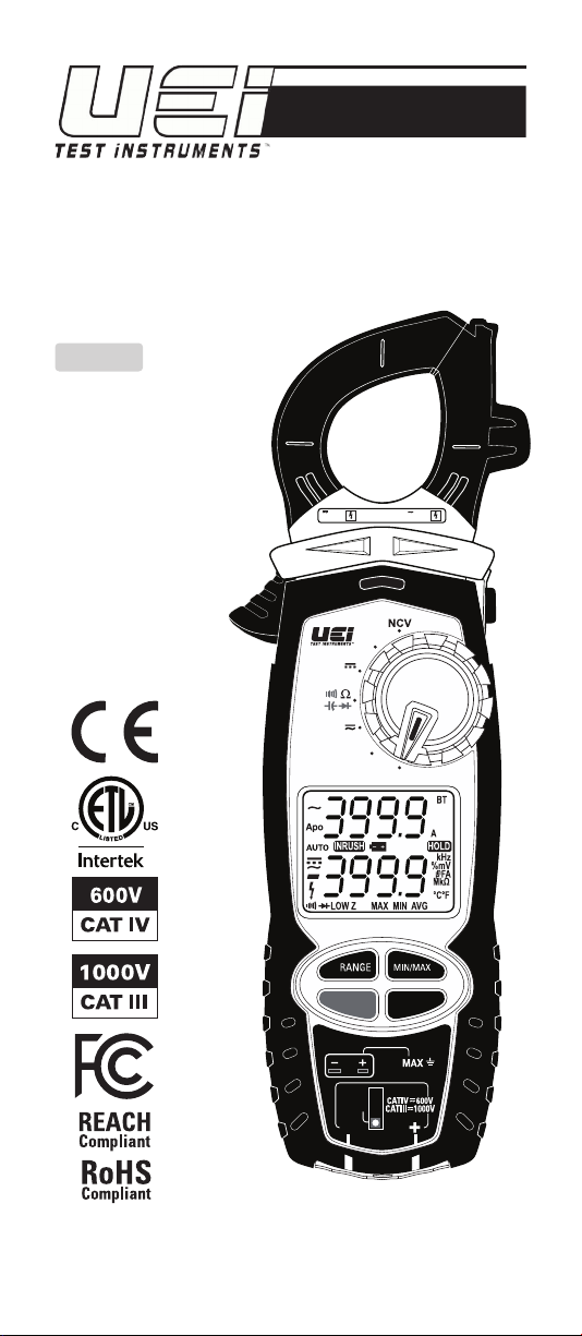
EPC
True RMS Everyday Professional
Clamp Meter
INSTRUCTION MANUAL
ENGLISH
CAT IV
600V 400A
°F°C
EPC
µA
V
TRUE RMS
OFF
EVERYDAY
PROFESSIONAL
CLAMP METER
Low Z
Hz/Duty
SELECT
INRUSH
BT
30V
TEMP
COM
1-800-547-5740
www.ueitest.com • email: [email protected]
Keeping Homes & Workplaces Safe & Comfortable
Page 2

Table Of Contents
FUNCTIONS ............................................................................................3
FEATURES .............................................................................................3
GENERAL SPECIFICATIONS
IMPORTANT SAFETY WARNINGS
SYMBOLS .............................................................................................5
CATEGORY DEFINITIONS
OVERVIEW
..................................................................................... 6 - 7
OPERATING INSTRUCTIONS
Low Z (Low Impedance) ........................................................... 7
AC Voltage: 750V AC ............................................................... 8
DC Voltage: 1000V DC ................................................................. 9
Frequency/Hz/Duty Cycle(%) .....................................................10
AC Amps: <400A – Jaw ........................................................ 11
Continuity ..................................................................................12
Resistance: < 40MΩ .................................................................12
Diode .........................................................................................13
Capacitance ................................................................................14
DC Microamps: <2000μA ..................................................... 15
Temperature F˚/C˚ ..................................................................... 16
Temperature Calibration ........................................................... 16
Non-Contact Voltage Detection (NCV) ................................... 17
LRA Inrush ..................................................................................17
App Overview ........................................................................... 18
Test Lead Notes .........................................................................19
Battery Replacement .................................................................19
WARRANTY .........................................................................................20
DISPOSAL
CLEANING
STORAGE
...........................................................................................20
...........................................................................................20
...........................................................................................20
.............................................................3
................................................. 4
...................................................................5
Functions
• True RMS
• 750V AC/1000V DC
• 400A AC
• DC microamps: 2,000µA
• Capacitance: 4,000µF
• Resistance: 40MΩ
• Diode test
• Audible continuity
• Frequency: 99.99kHz
• Duty cycle
• LRA Inrush
• Low Z (Low Impedance)
• Temperature range: -328˚ to 2462˚F
• Non-Contact Voltage Detection (NCV)
Features
• Dual display
• Back light
• Data Hold
• Min/Max/Avg
• Test lead storage
• Auto calibration
• Magnetic mount/strap
• Visible high-voltage alert
• Input jack locks
• Battery compartment latches
• Auto/Manual ranging
• Auto power off
• Low battery indicator
General Specifications
• Operating Temperature: 32˚ to 122˚F (0˚ to 50˚C)
• Storage Temperature: -4˚ to 140˚F (-20˚ to 60˚C)
• Temperature Coefficients: Add 0.15 x specified accuracy for each degree
> 82.4°F (28 °C) or < 64.4°F(18 °C)
• Operating Humidity: <80%
• Display: 3 3/4 digits 4,000 count
• Back light: Ye s
• Refresh Rate: 3/sec
• Over-range: “OL” is displayed
• Pollution Degree: 2
• Apo: Auto power off after 30 minutes of use.
• Dimensions: 9.6” x 2.6” x 1.3” (245.2mm x 66.5mm x 42.4mm)
• Item Weight: 0.65 lb (387g)
• CAT Rating: CATIV 600V, CATIII 1000V
• Certifications: cETLus UL 61010-1: 2012
• Battery Type: (AAA) 4
• Ingress Protection Rating: IP42
• Jaw Opening Size: 1.26”(32mm)
• Test leads: Silicone Test lead ATL58 w/alligator clips
2 3
Page 3
Important Safety Warnings
EF
k
WARNING
Read entire Safety Notes section regarding potential hazards and proper
instructions before using this meter. In this manual the word “WARNING” is
used to indicate conditions or actions that may pose physical hazards to the
user. The word “CAUTION” is used to indicate conditions or actions that may
damage this instrument.
WARNING
To ensure safe operation and service of the tester, follow these instructions.
Failure to observe these warnings can result in severe injury or death.
WARNING
• Before each use, verify meter operation by measuring a known voltage or
current.
• Never use the meter on a circuit with voltages that exceed the category
based rating of this meter.
• Do not use this meter during electrical storms or in wet weather.
• Do not use the meter or test leads if they appear damaged.
• Ensure meter leads are fully seated and keep fingers away from the metal
probe contact when making measurements. Always grip the leads behind
the finger guards molded into the probe. For information on test lead shields
instructions on page 19.
• Do not open the meter to replace batteries while the probes are connected.
• Use caution when working with voltages above 60 DC or 25 AC RMS. Such
voltages pose shock hazards.
• To avoid false readings that can lead to electrical shock, replace batteries if
a low battery indicator appears.
• Unless measuring voltage or current, shut off and lockout power before
measuring resistance or capacitance.
• Always adhere to national and local safety codes. Use proper personal
protective equipment (PPE) to prevent shock and arc blast injury where
hazardous live conductors are exposed.
• Always turn off power to a circuit or assembly under test before cutting,
unsoldering or breaking the current path. Even small amounts of current
can be dangerous.
• Always disconnect the live test lead before disconnecting the common test
lead from the circuit.
• In the event of electrical shock, ALWAYS bring the victim to the emergency
room for evaluation, regardless of victim’s apparent recovery. Electrical
shock can cause unstable heart rhythms that may need medical attention.
• If any of the following occur during testing, turn off the power source to the
circuit being tested: arcing, flame, smoke, extreme heat, smell of burning
materials or discoloration or melting of components.
WARNING
Higher voltages and currents require greater awareness of physical safety
hazards. Before connecting the test leads; turn off power to the circuit under
test, set meter to the desired function and range; connect the test leads to
the meter first, then connect to the circuit under test. Reapply power. If an
erroneous reading is observed, disconnect power immediately and recheck all
settings and connections.
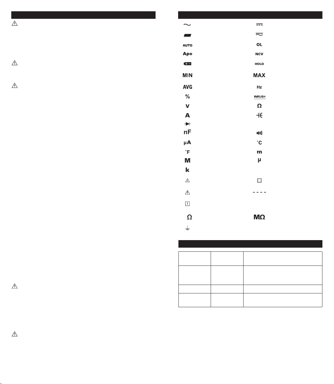
Symbols
AC (Alternating current) DC (Direct current)
Negative
Auto-ranging
Auto power off Active Non-Contact Voltage
Low Battery Hold/Capture Value
Minimum measured
value displayed
Average Hertz/Frequency
Duty Cycle Inrush
Voltage Ohms/Resistance
Amperage Capacitance
Diode
Nanofarad Continuity
Microamps Degrees Celsius
Degrees Fahrenheit Milli (x10-3 or 0.001)
Mega (x106 or 1,000,000) Micro (x10-6 or 0.000001)
Kilo (x103 or 1,000)
Warning or Caution
Dangerous Levels No reading detected
Safe for disconnect from
live conductors
Kilo Ohms Mega Ohms
Ground
AC/DC Voltage or Current
Overload: Range Exceeded
Maximum measured
value displayed
Microfarad
µF
Wireless Connection
BT
Double Insulation
(Protection to Class II)
Electric Field
Category Definitions
Measurement
Category
II < 10 Circuits connected to mains socket
III < 50 Mains distributions parts of the building
IV > 50 Source of the mains installation in the
Short-Circuit
(typical) kA
a
outlets and similar points in the MAINS
installation
building
Location in the
building installation
WARNING
This meter is designed to provide HVAC/R technicians with the capabilities they
need to diagnose and repair HVAC/R system. Observe all recommended
safety procedures that include proper lockout utilization and use of personal
protective equipment that includes safety glasses, gloves and flame resistant
clothing.
4 5
Page 4
Overview
L
A
B
CAT IV
C
600V 400A
D
F
°F°C
EPC
TRUE RMS
EVERYDAY
PROFESSIONAL
CLAMP METER
µA
V
OFF
Low Z
Hz/Duty
SELECT
INRUSH
BT
30V
TEMP
COM
G
H
I
J
K
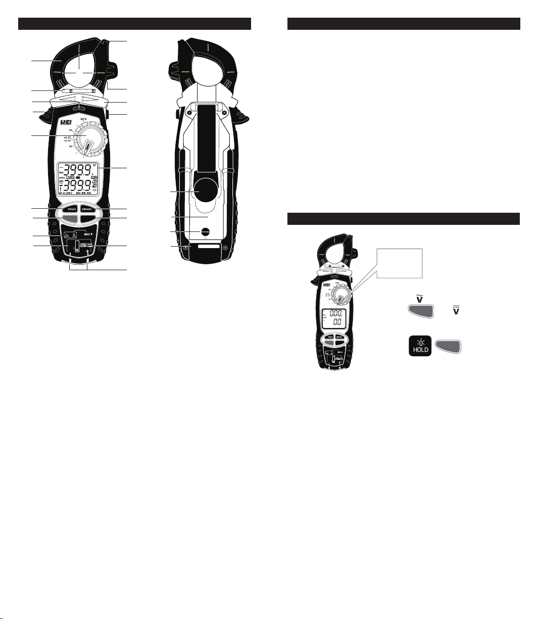
A. Clamp Jaw: Measure inductive AC current. Opens to 1.26” (32.0mm).
B. Conductor Alignment Marks: Use to aid the visual alignment of a
conductor when measuring inductive amperage. Greatest accuracy
is achieved when the conductor inside the clamp is centered at the
intersection of these marks.
C. Category Max Indicator: Maximum CAT Rating for clamp jaw.
D. NCV Alert Light: Indicates voltage when in NCV (Non Contact Voltage)
mode and High Voltage alert.
F. Clamp Lever: Opens and closes current clamp jaw.
NOTE: The clamp uses a high-tension spring to close the jaw. Do not
allow fingers or objects to become pinched in the base as the jaws close.
G. Rotary Selector Dial: Set Rotary Selector Dial desired function
H. Range Button:
• Press to set manual range desired
I. SELECT/BT Button:
• Press AC or DC on Low Z setting; AC or DC on Voltage setting;
to activate ohms, Continuity, Diode, Capacitance on Ohms/Continuity/
Diode/Capacitance setting; °C or °F temperature setting
• Press and hold to sync wirelessly to device
J. K-Type Temperature Probe Inputs
K. Input Jack Lock: Switch to use Temperature or Test lead inputs
L. Wire Separation Tab/ NCV sensor: Use to isolate an individual wire from
a bundle for testing. Non-Contact Voltage (NCV) detection sensor to check
for live voltage.
M. Test Lead Holder
N. Hand Guard: Used as a point of reference for the operator’s safety. Keep
hand behind guard when measuring from the clamp jaw.
O. Hold/Back light Button:
• Press to hold the reading on the display. Press again to return to live reading.
• Press and hold to turn on Back light.
• Backlight turn off after 60 seconds.
• Press and Hold during power up to disable the Auto power off function.
P. Display:
• High contrast dual display with backlit.
• AC Amps reading will always display on upper display.
M
N
O
P
U
Q
R
V
W
S/N:
S
X
T
6 7
Overview (Cont.)
Q. Min/Max Button:
• Press to enter MIN/MAX/AVG mode.
• Press to step through maximum(MAX), minimum(MIN), Average(Avg),
and present values.
• Press and hold return to Live readings
R. Hz/Duty INRUSH Button:
• Press to enter Hz/Duty in AC volt
• Press Select to step through Frequency, Duty Cycle, and to return to
live readings.
• Press and Hold to select LRA INRUSH mode (See page 17 for details)
S. Category Max Indicator: Maximum CAT Rating for input jacks.
T. Test Lead Input Jacks: Multifunction and Positive input jacks.
• Multifunction input port used for measuring: AC or DC volts, resistance,
continuity, diode, capacitance, DC μA.
U. Built-in versatile magnet to use as a mount or as a strap
V. Battery Cover: Easily replace batteries without breaking calibration seals.
W. Battery Compartment Latches: Easy access latches can be opened
without screwdriver.
X. Serial Number
Low Z (Low Impedance)
600V 400A
EPC
TRUE RMS
EVERYDAY
PROFESSIONAL
CLAMP METER
CAT IV
°F°C
µA
V
OFF
Low Z
V
Low Z
Hz/Duty
SELECT
INRUSH
BT
30V
TEMP
COM
Low Z
•
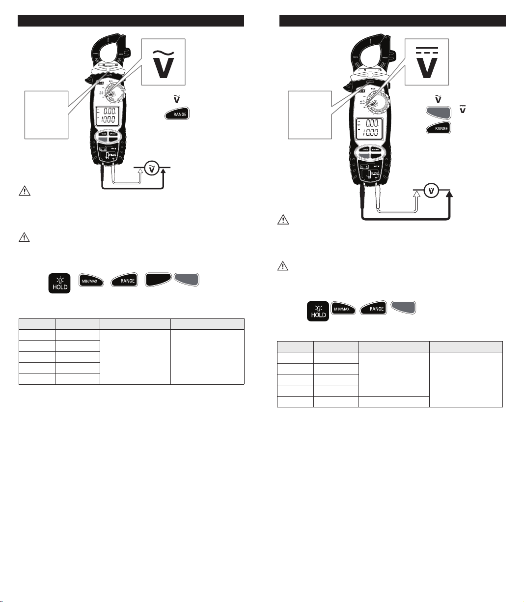
Rotate Selector Dial to Low Z
• Default =
• Press
Features:
SELECT
x1 =
BT
SELECT
BT
Page 5
Voltage 750V AC
CAT IV
600V 400A
°F°C
EPC
µA
V
TRUE RMS
OFF
EVERYDAY
PROFESSIONAL
High
Voltage
Alert
CLAMP METER
Low Z
AUTO
Hz/Duty
SELECT
INRUSH
BT
30V
TEMP
COM
WARNING
• Use CATIII rated test leads or higher.
• Do not attempt to measure more than 750V AC.
• Keep hands below line when measuring high current levels.
WARNING
• High Voltage indicator will display and audible alert will sound over 600V AC
• High Voltage indicator will display (without audible alert) over 30V AC
Features:
Range Resolution Accuracy Overload Protection
400.0mV 0.1mV
4.000V 0.001V
40.00V 0.01V
±2.0% + 5dgts 750V RMS
400.0V 0.1V
750V 1V
True RMS: 45Hz to 400Hz
V
• Default =
• Press
Hz/Duty
INRUSH
to select resolution
SELECT
BT
Voltage 1000V DC
CAT IV
600V 400A
°F°C
EPC
High
Voltage
Alert
TRUE RMS
EVERYDAY
PROFESSIONAL
CLAMP METER
AUTO
µA
V
OFF
Low Z
Hz/Duty
SELECT
INRUSH
BT
30V
TEMP
COM
WARNING
• Use CATIII rated test leads or higher.
• Do not attempt to measure more than 1000V DC.
• Keep hands below line when measuring high current levels.
WARNING
• High Voltage indicator will display and audible alert will sound over 600V DC
• High Voltage indicator will display (without audible alert) over 30V DC
Features:
DC Volts
Range Resolution Accuracy Overload Protection
400.0mV 0.1mV
4.000V 0.001V
40.00V 0.01V
±0.5% + 4dgts
4 00.0V 0.1V
1000V 1V ±0.8% + 10dgts
V
• Default =
• Press
• Press
SELECT
BT
SELECT
=
BT
to select resolution
1000V RMS
8 9
Page 6
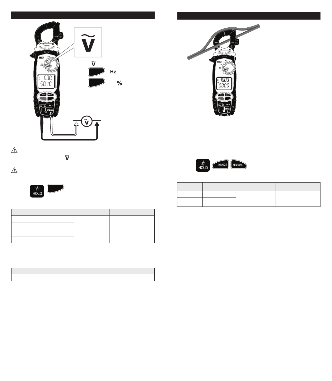
Frequency (Hz)/Duty Cycle (%)
AUTO
Hz
CAT IV
600V 400A
°F°C
EPC
µA
V
TRUE RMS
OFF
EVERYDAY
PROFESSIONAL
Low Z
CLAMP METER
Hz/Duty
SELECT
INRUSH
BT
30V
TEMP
COM
Use CAT III rated leads or higher.
Rotate Rotary selector Dial to position select AC voltage, press the button
for Frequency and Duty Cycle modes.
WARNING
Do not attempt to measure more than 750V AC.
Features:
Hz/Duty
INRUSH
Frequency Measurement - Test lead input
Range Resolution Accuracy Overload Protection
99.99Hz 0.01Hz
999.9Hz 0.1Hz
9.999kHz 0.001kHz
99.99kHz 0.01kHz
Minimum Frequency: 0.5Hz, DC V offset should be zero
Sensitivity: 1.6 Vrms
Duty Cycle - Test lead input
Range Accuracy Overload Protection
1.0 to 99.0% ±(0.2% per kHz + 0.1% + 5 dgts) 1000V RMS
• Default =
Hz/Duty
• Press
• Press
INRUSH
Hz/Duty
INRUSH
=
x2 =
0.1% + 4dgts 1000V RMS
AC Amps <400A Jaw
CAT IV
600V 400A
Single
°F°C
EPC
µA
V
TRUE RMS
OFF
EVERYDAY
PROFESSIONAL
Low Z
CLAMP METER
V
Hz/Duty
SELECT
INRUSH
BT
30V
TEMP
COM
• AC Amps can be measured in any position of the rotary selector dial.
• Center wire in guides for best accuracy.
• Opposing currents cancel each other (use line-splitter when necessary).
• Keep hands below guard when measuring high current levels.
• Do not attempt to measure more than 400A AC.
Features:
AC Amps Measurement - Jaw input
Range Resolution Accuracy Overload Protection
40.00A 0.01A
400.0A 0.1A
45Hz to 400Hz True RMS
Minimum Current for Clamp Measurement: 0.1A
Conductor
Only
• Rotary selector dial = Any position
other than NCV
Reading show on upper display
•
±2.0% + 8dgts 600V RMS
Frequency Range: 0.5Hz to 30kHz
Sensitivity: 1.6 Vrms
10 11
Page 7
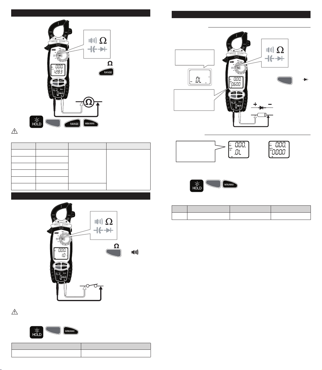
Resistance: < 40MΩ
CAT IV
600V 40 0A
Diode
GOOD DIODE
°F°C
EPC
µA
V
TRUE RMS
OFF
EVERYDAY
PROFESSIONAL
Low Z
Features:
CLAMP METER
SELECT
SELECT
BT
TEMP
COM
BT
kΩ
Hz/Duty
INRUSH
30V
• Default =
• Press
to select resolution
WARNING
• Do not measure resistance on a live circuit.
Range Resolution Accuracy Overload Protection
400.0Ω 0.1Ω
4.000kΩ 0.001kΩ
40.00kΩ 0.01kΩ
400.0kΩ 0.1kΩ
±1.0% + 4dgts
600V RMS
4.000MΩ 0.001MΩ
40.00MΩ 0.01MΩ ±2.0% + 4dgts
Continuity
CAT IV
600V 400A
CAT IV
600V 400A
Reverse Bias
Displays "OL"
Forward Bias
Displays approx.
voltage drop
TRUE RMS
EVERYDAY
PROFESSIONAL
CLAMP METER
°F°C
EPC
µA
V
OFF
Low Z
V
Hz/Duty
SELECT
INRUSH
BT
30V
TEMP
COM
• Default = Ω
• Press
SELECT
x2 =
BT
BAD DIODE
Open Diode
Displays "OL"
Both directions
• Forward voltage drop if forward biased.
• “O.L.” if reverse biased.
Features:
Diode Test
Range Open Circuit Voltage Test Current(Typical) Overload Protection
4.0V < 3.0V DC 0.25mA 600V RMS
SELECT
BT
or
V V
'0' Both directions
°F°C
EPC
µA
V
TRUE RMS
OFF
EVERYDAY
PROFESSIONAL
Low Z
CLAMP METER
AUTO
Hz/Duty
SELECT
INRUSH
BT
30V
TEMP
COM
• Buzzer sounds at less than < 40Ω.
• Default =
• Press
WARNING
• Do not measure resistance on a live circuit.
Features:
SELECT
BT
Open circuit voltage < 0.64V Overload Protection
Threshold Approx : < 40Ω 600V RMS
12 13
SELECT
BT
x1 =
Page 8
600V 400A
EPC
TRUE RMS
EVERYDAY
PROFESSIONAL
CLAMP METER
AUTO
CAT IV
°F°C
µA
V
OFF
SELECT
BT
TEMP
COM
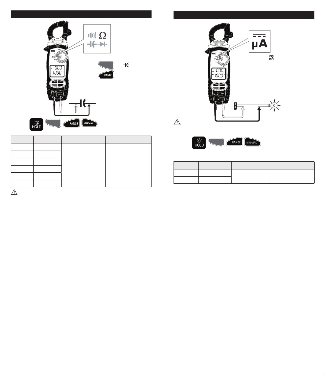
Capacitance
Low Z
µ
F
Hz/Duty
INRUSH
30V
• Default = Ω
• Press
• Press
SELECT
x3 =
BT
to select resolution
DC Microamps: <2000µA
CAT IV
600V 400A
°F°C
EPC
TRUE RMS
EVERYDAY
PROFESSIONAL
CLAMP METER
µA
V
OFF
Low Z
AUTO
µ
Hz/Duty
SELECT
INRUSH
BT
30V
TEMP
COM
• Default =
• Readings show on lower display
Features:
SELECT
BT
Range Resolution Accuracy Overload Protection
40.00nF
400.0nF
4.000µF
40.00µF
400.0µF
4000µF
0.01nF
0.1nF
0.001µF
0.01µF
0.1µF
1µF
3.5% + 6dgts 600V RMS
WARNING To avoid damaging the meter or equipment under test, safely
discharge Capacitors before measuring capacitance. Large value capacitors
should be discharged through an appropriate resistance load. Use the DC
Voltage function to confirm the capacitor discharge.
WARNING
• Do not attempt to measure more than 2000µA.
Features:
SELECT
BT
DC Microamps Measurement -Test lead input
Range Resolution Accuracy Overload Protection
400.0µA 0.1µA
2000µA 1µA
±1.2% + 3dgts 600V RMS
14 15
Page 9
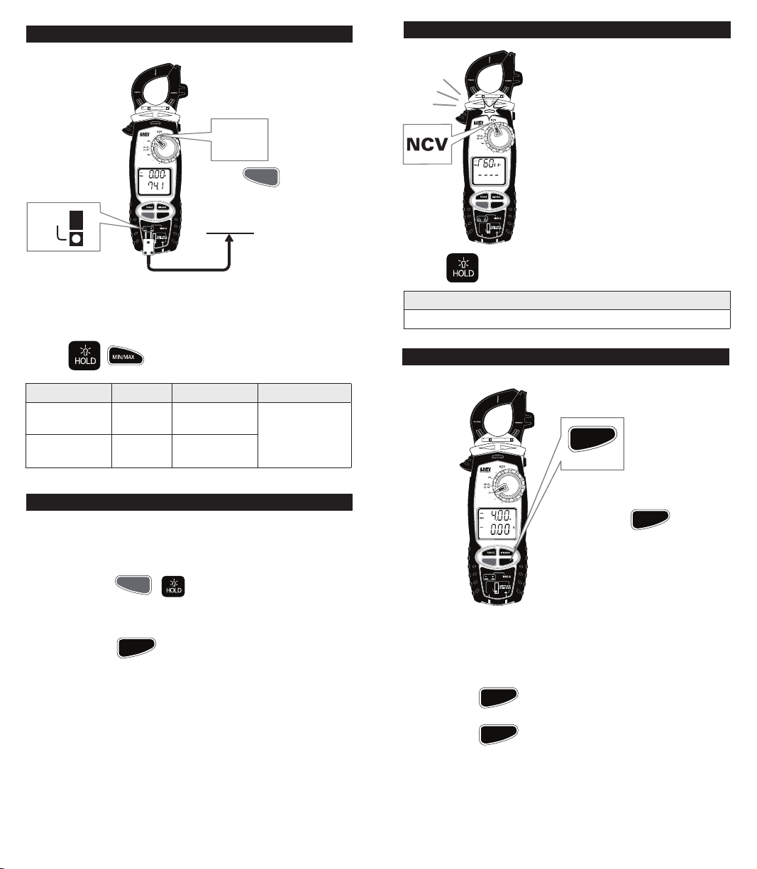
Temperature °F/°C
AUTO
AUTO
INRUSH
CAT IV
600V 400A
°F°C
EPC
TEMP
TRUE RMS
EVERYDAY
PROFESSIONAL
CLAMP METER
µA
V
OFF
Low Z
AUTO
°F
Hz/Duty
SELECT
INRUSH
BT
30V
TEMP
COM
Temp
SELECT
• Press
• Readings show on lower display
BT
= ˚F or ˚C
• Disconnect test lead probes from voltage source and meter.
• Move Input Jack Locks to “TEMP” setting.
• Use K-Type thermocouple temperature probes only.
• Stated accuracy does not account for thermocouple accuracy.
Features:
Range Resolution Accuracy Overload Protection
-328° to 999°F
(-200° to 999°C)
1000° to 2462°F
(1000°C to 1350°C)
0.1°F
(0.1°C)
1°F
(1°C)
±(1.0% + 3.6°F)
±(1.0% + 2.0°C)
±(1.0% + 3°F)
±(1.0% + 2°C)
30V RMS
Sensor: K-type Thermocouple, sensor accuracy not included.
Temperature Calibration
The new EPC clamp meter offers a digital field temperature calibration
procedure to make the process easier. Here are the steps.
1) Set dial position to “°F°C”
2) Press and hold
3) Press HOLD button while “FCAL” is displayed on top LCD to enter
Field Calibration mode.
4) After immersing temperature probe in ice bath and temperature is stable,
press and hold
SELECT
Hz/Duty
INRUSH
BT
+ button
button
Non-Contact Voltage
NCV Sensor in the tip.
• Rotate Rotary Selector Dial to NCV position
600V 400A
EPC
TRUE RMS
EVERYDAY
PROFESSIONAL
CLAMP METER
CAT IV
°F°C
µA
V
OFF
Low Z
move the tip of the clamp meter near
voltage source.
• Non-Contact Voltage Detection is used to
detect power with sensor located in the
tip of the clamp head, indicates positive
response with both an Audible and Visual
alert.
• Do not use Non-contact voltage detector
to determine if there is current on the wire.
Hz/Duty
SELECT
INRUSH
BT
30V
TEMP
COM
Detection operation could be affected by
socket design, insulation thickness, type or
other factors.
• Voltage indicator light may also light
when voltage (>AC/DC 30V) is present
Features:
on the meter’s input jack or from an
external interference such as motors,
flashlights, etc.
On Voltage
Approx. 24V AC
LRA Inrush
CAT IV
600V 400A
°F°C
EPC
µA
V
TRUE RMS
OFF
EVERYDAY
PROFESSIONAL
Low Z
CLAMP METER
Hz/Duty
SELECT
INRUSH
BT
30V
TEMP
COM
The UEi LRA Inrush is programmed to properly capture the starting current
for compressor motors. Inrush current can be measured in any position of
the rotary selector Dial.
Hz/Duty
INRUSH
• Rotary selector Dial = Any position other
than NCV
• Press and Hold
Hz/Duty
INRUSH
= INRUSH
• Select the range capable of capturing the maximum value.
• Press and Hold
Hz/Duty
button – INRUSH will now be shown on the screen.
INRUSH
• Activate the compressor and read value on the display.
• Press and Hold
16 17
Hz/Duty
button to return to live readings.
INRUSH
Page 10
4mm
S/N:
LOCK
OPEN
LOCK
OPEN
App Overview
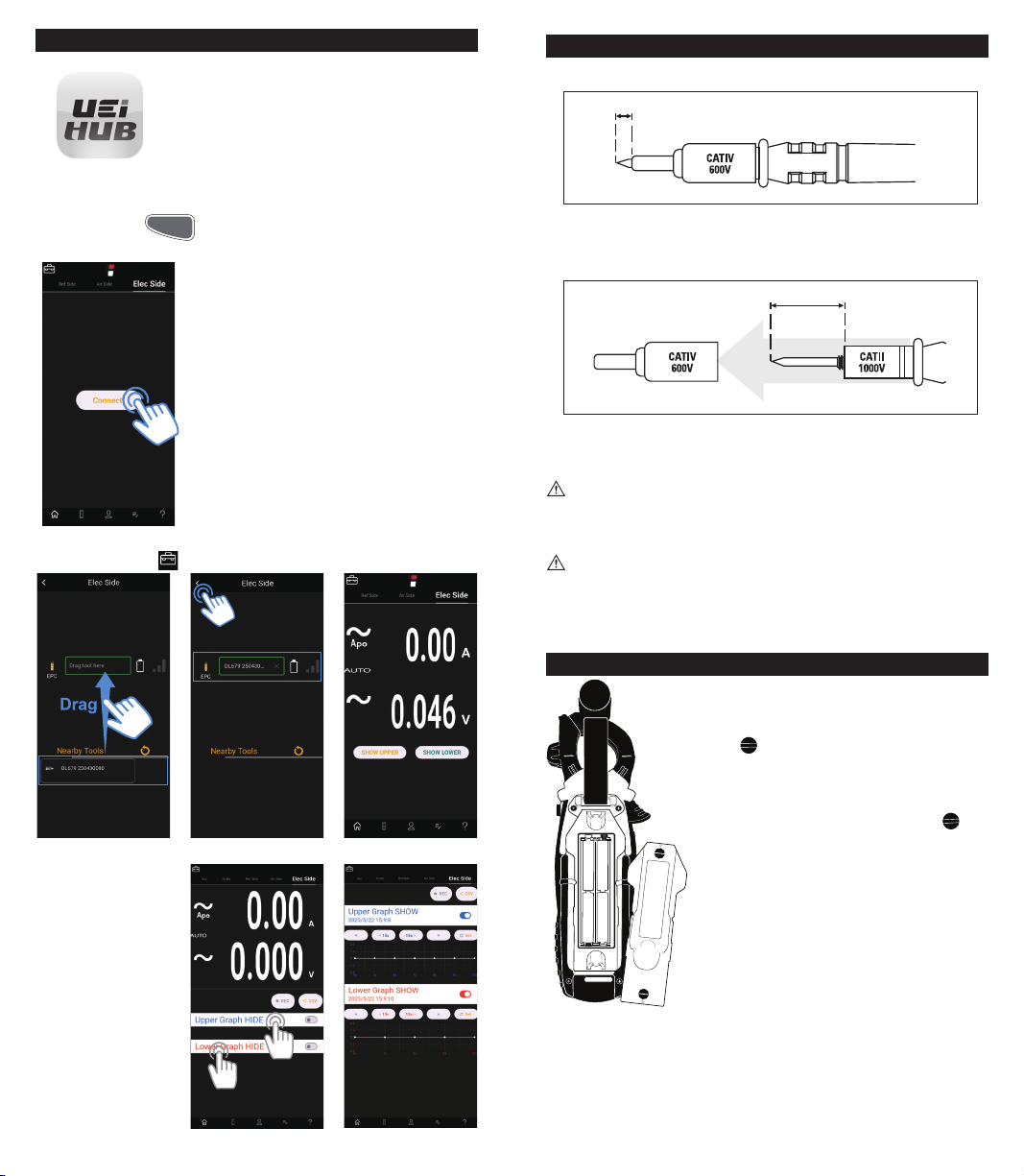
• In the App stores Google Play and the App Store,
search “UEi HUB”.
• App is compatible with iOS® 14.0 and up and
Android™ 10.0 and up. If searching for the iPad
version, you may have to filter for “iPhone” only.
• Turn on EPC and launch the UEi HUB App on device.
• On EPC, Press and hold SELECT / BT. Beep confirms wireless mode
activated. BT shows in display.
• Press and Hold
• On Device, Press CONNECT to pair device
• Go to “Elec Side” screen and connect your EPC
• Click on “Toolbox” icon in the upper left of screen
SELECT
button to activate wireless connection
BT
Test Lead Notes
Cat IV and CAT II Measurement Locations
4mm
• Ensure the test lead shield is pressed firmly in place. Failure to use the CAT
IV shield increases arc-flash risk.
CAT II Measurement Locations
18mm
• CAT IV shields may be removed for CAT II locations. This will allow testing
on recessed conductors such as standard wall outlets. Take care not to lose
the shields.
WARNING: Test Lead category protections apply only to test leads and
should not be confused with the meter’s specific CAT rating. Observe the
maximum category protection indicated on the meter the test leads are
plugged into.
CAUTION: If the test leads need to be replaced, you must use a new one
which should meet EN 61010-031 standard, rated CATIII 1000V or better.
• Click to “Show Upper”
and “Show Lower”
button to display mesaurement graph.
Click “Hide Upper”
and “Hide Lower” to
return.
Battery Replacement
• Rotate Battery Compartment Latches to open
position
• Remove battery cover
• Replace the old batteries with 4 new (AAA) batteries
• Replace the battery cover
• Rotate Battery Compartment Latches to lock
18 19
Page 11

Warranty
The EPC is warranted to be free from defects in materials and workmanship
for a period of 2 years from the date of purchase. If within the warranty period
your instrument should become inoperative from such defects, the unit will
be repaired or replaced at UEi’s option. This warranty covers normal use and
does not cover damage which occurs in shipment or failure which results
from alteration, tampering, accident, misuse, abuse, neglect or improper
maintenance. Batteries and consequential damage resulting from failed
batteries are not covered by warranty.
Any implied warranties, including but not limited to implied warranties of
merchantability and fitness for a particular purpose, are limited to the express
warranty. UEi shall not be liable for loss of use of the instrument or other
incidental or consequential damages, expenses, or economic loss, or for any
claim or claims for such damage, expenses or economic loss.
Warranty only covers hardware and does not extend to software applications.
A purchase receipt or other proof of original purchase date will be required
before warranty repairs will be rendered. Instruments out of warranty will be
repaired (when repairable) for a service charge.
For more information on warranty and service, contact:
www.ueitest.com • Email: [email protected]
1-800-547-5740
This warranty gives you specific legal rights. You may also have other rights,
which vary from state to state.
Disposal
CAUTION: This symbol indicates that equipment and its accessories
shall be subject to separate collection and correct disposal.
Cleaning
Periodically clean your meter’s case using a damp cloth. DO NOT use abrasive,
flammable liquids, cleaning solvents, or strong detergents as they may damage the
finish, impair safety, or affect the reliability of the structural components.
Storage
Remove the batteries when instrument is not in use for a prolonged period of time.
Do not expose to high temperatures or humidity. After a period of storage in extreme
conditions exceeding the limits mentioned in the General Specifications section, allow
the instrument to return to normal operating conditions before using it.
Copyright © 2025 Kane USA Inc. All Rights Reserved. 202153 05/25
 Loading...