

Page 1

1-800-547-5740 • Fax: (503) 643-6322
www.ueiautomotive.com • email: info@ueiautomotive.com
ACM6000
INSTRUCTION MANUAL
Page 2

• Even moderate amounts of current can cause ventricular fibrillation
• Use insulated tools and gloves to avoid electrical shock
• Disconnect wiring from supply voltage before performing
continuity tests
• Disconnect the negative battery terminal when removing and
replacing starters, alternators, and other components that have
direct connections to the battery
Multimeter Safety Precautions
When making resistance measurements, ensure no voltage is present
in the component or wire being tested. When making voltage or
current measurements, ensure you don’t exceed the maximum rating
of the ACM6000.
International Symbols
C o n t r ols and Indicators
1. Rotary Selector Knob: Switches measurement function.
2. ZERO button: In the DC AMP’s mode, this control zero’s the display,
so the user can get the most accurate DC current reading.
3. Test lead input terminals
• Positive input (red terminal) for:
• Voltage
• Temperature
• R e s i s t a n c e
• Negative input (black terminal) for: used as common, ground
or low-side input for all test lead measurements.
4. ON/OFF switch: Slide the switch forward to turn the instrument
on, slide it back to turn the instrument off.
5. HOLD button: Freezes the display.
Introduction
The ACM6000 DC/AC Clamp Meter instrument allows pocket sized
convenience for testing voltage, current flow, resistance, continuity
and temperature.
A voltage measurement does not always provide complete information
about the behavior of a circuit. A current measurement, in addition to
the voltage measurement, provides additional information to help you
make a correct diagnosis.
The instructions, recommendations and illustrations in this manual are
intended the basic information necessary to get you started on the path
to automotive electrical diagnostics.
State-of-the-art electronic test tools are not very effective without understanding basic automotive electrical diagnostics and basic electrical circuits. Training courses are usually available from local schools. For
additional information on domestic field training, contact the UEI
Automotive Field Training Center at (770) 476 -1431 (8-5 PM, EST).
Custom contract training can be provided in your area.
Safety Notes
Before using this meter, read all safety information carefully. In
this manual the word "WARNING" is used to indicate conditions
or actions that may pose physical hazards to the user. The word
"CAUTION" is used to indicate conditions or actions that may
damage this instrument.
WARNING!
Follow appropriate work area safety precautions
Automotive safety
When performing vehicle maintenance, work in a well-ventilated
area - route exhaust gases out of work area. Work in a well-lit
environment. Use supplemental work lights in service area.
• DO NOT wear jewelry (rings, watches, etc.) when
working on vehicles
• Wear approved safety eyewear at all times
• Avoid rotating fan blades, drive-belts and pulleys on
running engines
• Beware of electrical shock when working on vehicle wiring and
electrical systems
• Keep open flames and sparks away from batteries, engine fuels
and oils
ACM6000-MAN P. 1
1
2 3
5 4
Page 3

Clamp-on techniques for current testing
Traditional current measurement involves opening a suspect circuit and
connecting the meter in series. However, opening a circuit to perform a
current flow test creates its own set of problems such as:
• Accessing/removing/replacing a computer, module or other
device from a hard-to-get area
• Cutting and then repairing a wire
• Reprogramming data that was lost when a circuit was opened
The ACM6000 Clamp Meter allows the technician to quickly and easily
make a non-intrusive current flow measurement by clamping the jaw
around a wire.
AC and DC voltage testing
Automotive technicians routinely use a DMM to make voltage checks of
the battery and various circuits. The ACM6000 permits the user to make
standard AC/DC voltage tests, resistance and continuity tests, tempera t u r e
tests and non-intrusive current tests, while enjoying shirt pocket convenience.
• Use the DC Voltage Measurement capability ( V ) to test any
circuit or device that is powered by battery or regulated voltage
• Use the AC Voltage Measurement capability ( V ) to test any
circuit that generates its own voltage, such as a magnetic type
trigger pickup, ABS, or crank-sensor
Resistance measurement (Ohms - Ω) testing
The ACM6000 can be used to measure how much electrical resistance
is present in a circuit or across a connector. The meter sends a small
current through the circuit being tested to calculate resistance.
Continuity testing
In order to assist the technician who may not be able to see the
meter display at the same time he is making test lead connections,
the instrument sounds a buzzer when measured resistance is
approximately 25 Ohms or less, which indicates there is continuity
and not an open circuit.
ZERO adjustment
DC Current Measurement is most accurate when the instrument is
zeroed before making the measurement. By pressing the ZERO button
for one or two seconds, the display reading is reset to approximately
00.0. Note: Some flicker of the least significant digit – the rightmost
digit – is normal due to the presence of electrical and magnetic forces
present from shop lighting, wiring, and other live electrical sources
near the test area.
Data hold
• Press the HOLD button to freeze the display reading
• Press the HOLD button again to resume real time readings
Wire to be tested must
pass through the opening
when clamp-jaw is shut.
Press there to open
clamp-jaw.
Display
1. Battery Low Indicator: If the letters “BAT” are displayed, turn
off the meter and replace the battery.
2. Minus Sign (-): Indicates negative polarity.
3. Measurement Display: This meter can display numbers up
to 199.9 on the LCD. The units (ohms, volts, etc.) are displayed as
symbols to the right of the digital value.
NOTE: A 1 on the left side of the display indicates that the input
has exceeded the selected range.
Features
AC and DC current testing
Frayed wiring, corroded or degraded connections, failing switches, etc.
may test OK for voltage but may not allow sufficient current for the
circuit to function properly. Technicians can make better informed
diagnostic decisions when circuit current (amperage) is also tested.
The ACM6000 can be used to test for both AC and DC current. The user
selectable range switch allows for measurement up to 200 Amps.
ACM6000-MAN P. 2
2
1
3
Page 4

Low battery indicator
The LOW BATTERY i n d i c ator displayed in the upper left hand corner of
the display screen alerts the operator to replace the ACM6000 battery.
• See “Battery Replacement” for detailed instructions
Temperature measurement
Automotive repair and maintenance often involves checking the
temperature of A/C and heating duct air as well as engine coolant
temperature. The operator may read temperature by connecting any
standard K type thermocouple to the input jacks, through the supplied
temperature probe adapter.
Hand strap
A Hand Strap is provided to avoid accidentally dropping the ACM6000
Clamp Meter.
Pouch
A pouch is provided for storage of the ACM6000 Clamp Meter, the
accessories and the operator’s manual.
Operating Instructions
AC/DC current testing
The procedure for measuring current using the ACM6000 is different
from measuring voltage.
• To measure VOLTAGE, the meter leads are connected to the points
in the circuit being tested
• To measure CURRENT, the jaws of the Clamp Meter are placed
around a wire or cable to make the measurement (Ensure test
leads are not connected to the meter)
1. To measure high AC CURRENT: Turn the rotary
function switch to the 200 Amps AC setting (200A ).
To measure high DC CURRENT: Turn the rotary function switch
to the 200 Amps DC setting (200A ).
2. Slide the ACM6000 power switch to the ON position.
3. Press the ZERO button (DC current measurements, only).
This will zero the instrument for the most accurate reading.
4. Place the jaws of the ACM6000 around the conductor
being tested.
• Verify that the instrument and its strap do not
touch moving pulleys or belts
• Failure to obey the current flow polarity indicator
arrow located on the inner jaw face will result in a minus
sign to the left of the amps readout
• Be sure the jaws are closed, leaving no air gap between
the two jaws.
A. Remove the instrument from the conductor
B. Turn the rotary switch to the 20A scale
C. Follow steps 3 and 4
5. When testing is completed move the instrument power switch
to OFF.
Measuring AC voltage
NOTE: Observe safety rules.
WARNING!
• Be certain that wires and leads, as well as clothing and hands
are clear of moving parts
• When checking ABS wheel speed sensors be sure the wheels
are free to rotate and will not move the vehicle or cause damage
1. Slide the ACM6000 power switch to the ON position.
2. Turn the rotary function switch to V.
3. Connect the test leads to the meter.
A. Plug the black lead into the COM input
B. Plug the red lead into the VΩ˚F input
4. Connect the probe tips to the circuit under test. For automotive
AC voltage measurements using a multimeter not necessary to
observe polarity.
NOTE: If the voltage readout is not stable, further evaluation of the
c i r cuit using a labscope is re c o m m e n d e d .
5. When testing is completed move the instrument power switch
to OFF.
Measuring DC voltage
1. Slide the ACM6000 power switch to the ON position.
2. Turn the rotary function switch to V.
3. Connect the test leads to the meter.
A. Plug the black lead into the COM input
B. Plug the red lead into the VΩ˚F input
4. Connect the black COM probe tip to the ground (-) side of the
circuit under test.
5. Connect the red prove tip to the positive (+) side of the circuit.
• The voltage present in the circuit is shown on the display
panel readout
• Instrument will indicate the polarity of the red lead
connection displayed on the left side of the voltage readout
NOTE: If the voltage reading is not stable, further
evaluation of the circuit using a labscope, model ADL7000
or ADL7100, is recommended.
6. When testing is completed move the instrument power switch
to OFF.
Resistance measurement
• The ACM6000 supplies a small current to the circuit under
test which is used to determine the circuit’s resistance
• Displays circuit resistance in Ohms (W)
ACM6000-MAN P. 3
Page 5
WARNING!
The circuit being tested must be turned OFF!
(NO VOLTAGE PRESENT).
• Use the built-in DMM to verify that the circuit under test is
turned OFF and no voltage is present.
Measuring resistance (Ohms Ω)
1. Slide the ACM6000 power switch to the ON position.
2. Turn the rotary function switch to Ω.
3. Connect the test leads to the meter.
A. Plug the black lead into the COM input
B. Plug the red lead into the VΩ˚F input
4. Verify that the circuit under test has no voltage applied.
5. Connect the test leads across the load or circuit to
be tested.
6. Read the circuit resistance displayed in Ohms.
7. When testing is completed move the instrument
power switch to OFF.
Testing continuity
Continuity is the measure of a circuit’s ability to conduct current as
opposed to resisting current flow.
• The Audible Continuity buzzer will sound when resistance
is under approximately 25Ω
• To set for continuity, follow the same procedures
prescribed for measuring resistance
• The same precautions apply
Measuring temperature
1. Slide the ACM6000 power switch to the ON position.
2. Turn the rotary function switch to ˚F.
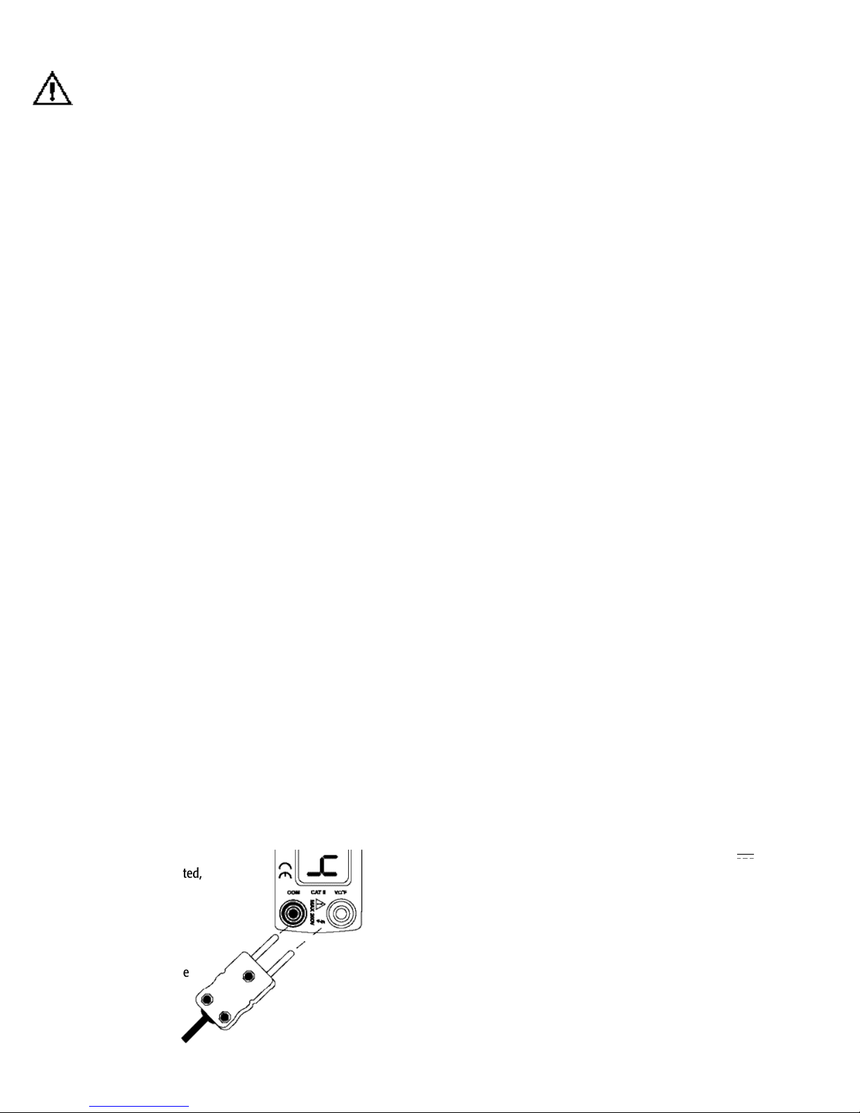
3. Connect the banana plugs of the thermocouple adapter
into the meter inputs (Fig. 1). Observe polarity.
4. Connect the K-type thermocouple to the
thermocouple adapter.
5. The temperature reading can be read on the
display panel.
6. When testing is completed,
move the instrument
power switch to OFF.
Plug the standard K-type
thermocouple into this
side of the adapter.
DC current testing
When investigating electrical circuit problems the tools most often
used by the automotive technician are the trouble light and the
volt/ohm meter or DMM. The trouble light is often the tool used to test
for current. However, most trouble lights have severe limitations:
1. The operator must guess at the amp draw based upon the
brightness of the bulb. Modern automotive circuits require precise
current loads. Accurate current measurements are crucial.
2. Many trouble lights require up to 2 amps to shine brightly.
If used to test a circuit designed for less amperage, the 2 amp
draw can over load the circuit resulting in damage.
3. Some DMMs have a built-in current testing feature. When using
most DMM’s to measure amps, it is necessary to open the system
under test and connect the DMM in series. While the test result is
accurate, the hook-up is time consuming and often impractical.
The ACM6000 Clamp Meter is a preferred alternative. By simply
placing the Clamp Meter around a power – or ground - wire of the
circuit being tested, the connection is made. No back probing or
intrusion of insulation is necessary. Additionally, the sensitivity and
resolution of the ACM6000 gives a precise amperage readout rather
than an estimate based upon bulb brightness. Because no direct
connection is required, there is no danger of overloading the circuit.
Re-connecting or reattaching wires is unnecessary.
NOTE: The ACM6000 Clamp Meter is designed to give accurate
measurement of continuous current flow. If the device being tested
is pulsed (like solenoids and relays) the readout will show the
average current.
For testing recommendations of pulsed circuits contact the UEi Training
Coordinator at 770/476-1431.
Starter current draw
Most starters draw several hundred amps initially, to start the crankshaft
turning. After about one half second the starter current will stabilize for
the duration of cranking. Typical starter current draw (after the initial
surge is):
• 4 cylinder - 120 amps
• 6 cylinder - 150 amps
• 8 cylinder - 180 amps
Test procedure:
1. Disable ignition or fuel, this is a cranking test.
2. Turn the ACM6000 rotary function switch to 200A .
3. Slide the instrument power switch to ON.
4. Verify that the vehicle ignition switch is in the OFF position.
5. Place the jaws of the ACM6000 around the starter cable and
be sure the jaws are closed.
6. Press the ACM6000 ZERO button. The display screen should
read approximately 00.0.
ACM6000-MAN P. 4
(Fig 1)
ATA1 Temp
Probe Adapter
Page 6

ACM6000-MAN P. 5
WARNING!
Observe proper safety procedure for step 7. Be certain the vehicle
cannot move during the cranking portion of the test.
7. Crank the engine while observing the meter reading.
CAUTION!
Avoid overheating the starter limit cranking time to 15 seconds.
8. When testing is completed move the instrument power switch
to OFF.
Abnormally high current can indicate:
• Over-advanced engine timing
• Seized engine
• Faulty starter
Abnormally low current can indicate:
• Low compression engine
• High resistance in starter circuit or connections
• Faulty battery - to check the condition of the battery, use
the voltmeter to perform a cranking voltage test
Parasitic load
Parasitic Load is the small amount of current drawn from the battery
after the ignition switch is turned OFF and the various electronically
controlled devices have phased from "Awake" to "Asleep" mode.
Typically, the parasitic load will be under 20 milliamps. In some
applications parasitic load will reach 40 milliamps and still be normal.
Check the vehicle service manual for exact specifications.
Test procedure:
1. Turn the ignition switch and all accessories OFF.
2. Disable the under-hood light.
3. Allow sufficient time for all the electronic devices to be asleep.
• Some devices take hours
• Refer to the vehicle service manual for exact time
4. Turn the ACM6000 rotary function switch to 20A .
5. Slide the instrument power switch to ON.
6. Press the ACM6000 ZERO button. The display should read
approximately 00.0.
7. Place the jaws of the ACM6000 around the battery positive
cable(s) or the battery negative cable(s). Either way will work.
Be sure the jaws are closed.
8. Because the display readout can vary up to 60mA, add 60mA
to the highest expected reading for parasitic load of the vehicle
under test. If the display readout exceeds that amount, further
testing is recommended.
Example: Normal highest parasitic load for vehicle under test is
40mA. Add 60mA to the expected 40mA for a total of 100mA. If
the display is 0.10A (100mA) the parasitic load can be considered
normal. However, a reading of 0.11 A (110mA) or more would
be too high.
Alternator output
Problems involving hard starting because of low battery current can be
caused by a faulty alternator. The alternator is responsible for keeping
the battery charged. The ACM6000 provides an easy way to check alternator current output.
Test procedure:
1. This test should be conducted with the battery fully charged.
• Charge the battery if necessary
2. Start engine and run at about 1800 RPM.
3. Allow sufficient time for all the electronic devices to be asleep.
4. Turn the ACM6000 rotary switch to 200A .
5. Slide the instrument power switch to ON.
6. Press the ACM6000 ZERO button. The display should read
approxiametly 00.0.
7. Using CAUTION to avoid moving belts, etc., place the jaws
of the ACM6000 around the alternator output wire. Be sure that
the jaws are closed.
8. Compare reading with manufacturers specifications.
9. When testing is completed move the instrument power switch
to OFF, and remove the meter from the wire.
Measuring amp output is only a partial indicator of alternator function
and ability to keep the battery charged. Performing a Regulator –
Operating Voltage test is also recommended.
Blower motor current draw
Modern automotive heating and air conditioning systems can be quite
complicated. Diagnosing these systems may require the use of a service
manual to help isolate the exact problem. However, it is often possible
to make quick work of pin-pointing some problems by using the
ACM6000 to measure current flow. Blown A/C fuses or insufficient
cooling/heating caused by a faulty blower motor are easy to find
using the ACM6000.
Test procedure:
1. To test the blower motor: disconnect the vehicles electrical
harness from the blower motor.
2. Connect a fused jumper lead set from the battery to the
blower motor.
3. Turn the ACM6000 rotary function switch to 200A .
4. Slide the instrument power switch to ON.
5. Press the ACM6000 ZERO button. The display should read
approximately 00.0.
6. Place the jaws of the ACM6000 around one of the two wires,
either one will work.
Page 7

ACM6000-MAN P. 6
7. Most blower motors draws about 25 amps at battery voltage.
Verify normal current draw specifications for the type of motor
you are testing.
• Excessive amperage indicates a faulty blower motor
probably due to an internal short
• Insufficient amperage indicates a faulty blower motor
probably due to high electrical resistance, either internally
or in the connector paths
8. When testing is complete move the instrument power switch to
OFF, and remove the meter from the wire.
Fuel pump current draw
Diagnosing fuel pump problems can sometimes be difficult. The
ACM6000 can be used to make a quick check for fuel pump current
draw during cranking. A fuel pump related problem possibly exists if
current flow is 2 amps or less during cranking. Additional testing may
be necessary if current flow is more than 2 amps.
Test procedure:
1. Disable the ignition system. This is a cranking test.
2. Turn the ACM6000 rotary function switch to 20A .
3. Slide the instrument power switch to ON.
4. Press the ACM6000 ZERO button. The display should read 00.0.
5. Place the jaws of the ACM6000 around the power wire to the
fuel pump. Be sure the jaws are closed.
WARNING!
Observe proper safety procedures for step 6. Be certain the vehicle
cannot move during the cranking portion of this test.
6. Observe the fuel pump current draw reading while an assistant
cranks the engine:
• Press the ACM6000 HOLD button to freeze the reading
• Press the HOLD button again to release the HOLD feature
7. When testing is complete, move the instrument power switch
to OFF.
Detailed evaluation of fuel pump performance can be made using the
Automotive Labscope.
Lamps, lights and electric motors
Devices such as headlamps, stop lights and interior lights as well as electric
motors (wiper, seat, mirror, etc.) draw current at a steady rate. The
ACM6000 can be used to verify the current flow powering these devices.
Measuring current in suspect circuit:
1. Turn the ACM6000 rotary function switch to 200A .
2. Slide the instrument power switch to ON.
3. Press the ACM6000 Z ERO button. The display should read
approximately 00.0.
4. Place the jaws of the ACM6000 around the positive (+) wire
of the circuit under test.
5. Note the display readout. Lights and motors should not draw
whole amps of current until switched ON.
6. Switch power to the suspect circuit ON and verify that current
draw does not exceed normal limits for that circuit.
7. When testing is complete, move the instrument power switch
to OFF, and remove the meter from the wire.
AC voltage testing
Some sensors produce their own voltage as an AC output. AC devices
include: The ABS Sensor, the Magnetic Crank Sensor, Magnetic
Distributor Pickup, and the Alternator. These devices operate at speeds
that are too fast for a meter to be able to give exact measurements of
each pulse. The meter reading is an averaged measurement. When
more detailed analysis of an AC device it is necessary, use a Labscope.
Measuring AC Voltage:
1. Slide the ACM6000 power switch to ON.
2. Turn the rotary function switch to V.
3. Connect the test leads to the meter.
A. Plug the black lead into the COM input
B. Plug the red lead into the VW˚F input
4. Connect the probe tips to the circuit under test. For AC sensor
voltage measurements with a multimeter, it is not necessary to
observe polarity.
WARNING!
• Be certain that wires and leads, as well as clothing and
hands are clear of moving parts
• When checking ABS wheel speed sensors be sure the wheels
are free to rotate and will not move the vehicle or cause damage
5. When testing is complete move the instrument power switch
to OFF.
Diagnostic tips:
• Heat and vibration can degrade sensor magnets, causing
reduced voltage or erratic voltage and current output
• Cracked magnets create unstable signals and erratic
computer responses
• Frayed wiring and poor connections frequently cause voltage
and current flow problems on AC sensors
• Check clearance between magnet and pickup against
manufacturer’s specifications
Page 8
ACM6000-MAN P. 7
DC voltage testing
Most electric/electronic devices in an automobile rely upon Direct
Current. Voltage will always have a direct relationship to current. It is
important that the voltage be appropriate for the need.
• When voltage is too low, insufficient power can cause problems Bulbs become dim, motors can slow down, and relays will
often malfunction
• When voltage is too high, devices are overpowered and bulbs
will burn out prematurely, motors can run too fast and fail early,
relays with fine wiring may overheat and fail
Use the DMM DC Voltage Testing capability of the ACM6000 to make
these important voltage tests.
NOTE: Modern automotive engine management systems utilize
computers and pulsed electronic solenoids in order to achieve the
best combination of power, fuel efficiency and low emissions. Those
pulsed devices are often on for only a few thousandths of a second
at a time. In some situations the on pulse lasts only a few millionth
of a second. The tool of choice to test pulsed circuits is a highperformance Labscope, like the ADL7000 or ADL7100. These
Labscopes sample the circuit millions of times per second.
Battery - state of charge
When conducting starting and charging system tests the first step is to
verify that the battery is fully charged.
1. Place the vehicle ignition switch in the OFF position.
2. Turn the headlights ON for 30 seconds to dissipate the battery
surface charge.
3. Slide the ACM6000 power switch to the ON position.
4. Turn the ACM6000 rotary function switch to V.
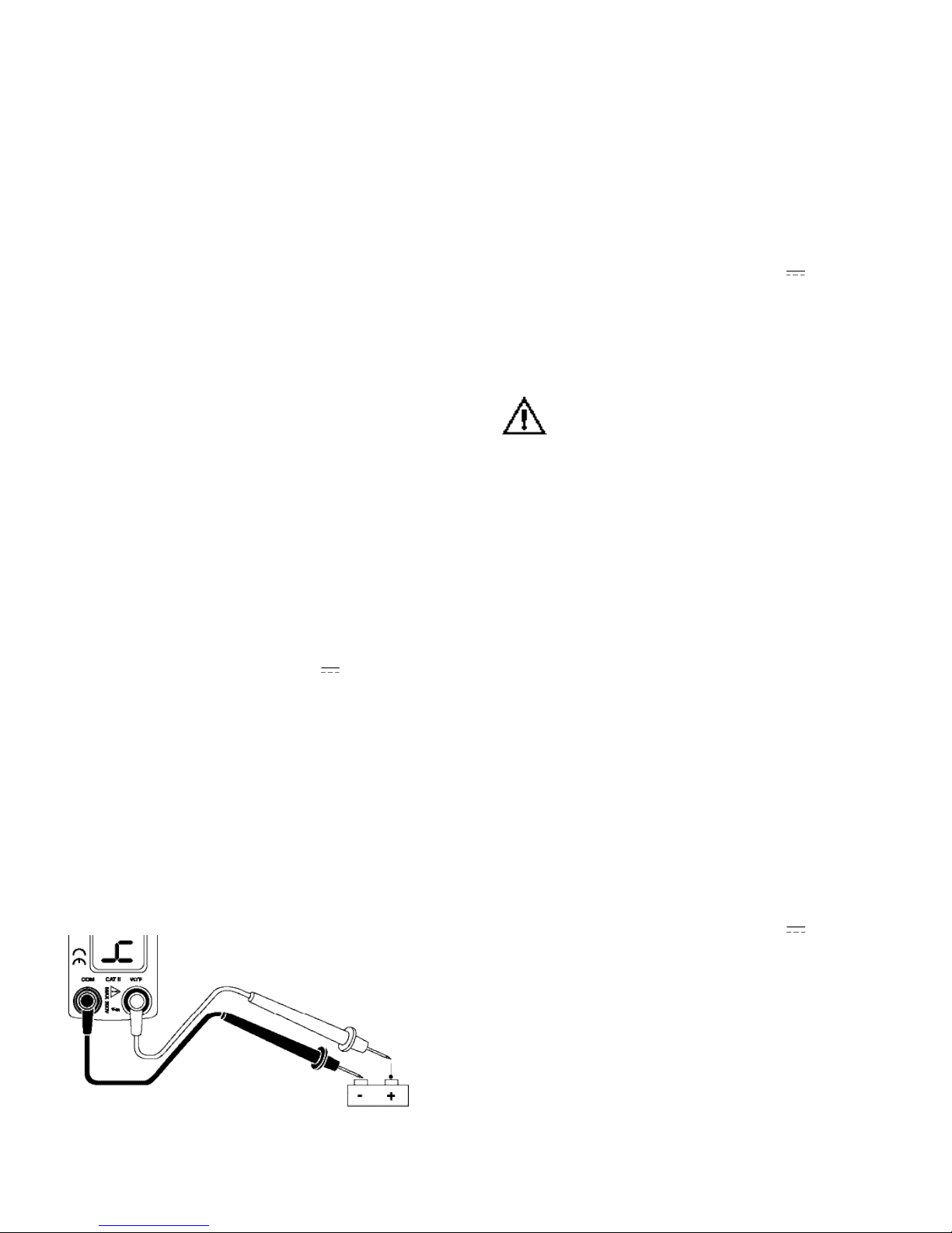
5. Connect the test leads to the meter (Fig 2).
A. Connect the black COM lead probe tip to the battery
negative (-) post
B. Connect the red VW˚F lead probe tip to the battery
positive (+) post
• A fully charged battery will read 12.6 volts or more
• A reading of 12.4 to 12.5 is considered about 75% charged
• If the reading is 12.3 volts or less, charge the battery
before making further starting and charging system tests
6. When testing is complete, move the instrument power
switch to OFF, and disconnect the test leads.
Battery - cranking voltage
By comparing the Battery – Cranking Voltage test result with the Starter
Current Draw test result, the technician can determine if a battery
should be replaced.
Test procedure:
1. Verify that the battery state of charge is ok.
2. Disable ignition or fuel so the engine will crank but not run.
3. Slide the ACM6000 power switch to the ON position.
4. Turn the ACM6000 rotary function switch to V.
5. Connect the test leads to the meter.
A. Connect the black COM lead probe tip to the
battery negative (-) post
B. Connect the red VW˚F lead probe tip to the
battery positive (+) post
WARNING!
Observe safety procedures for step 7. Be certain the vehicle can not
move during the cranking portion of the test.
6. Crank the engine while observing the meter reading. To avoid
overheating the starter, limit cranking to 15 seconds.
• Look for a reading of 9.6 volts or higher when testing at 70˚F
• In colder conditions allowing 0.1 volt less for each 10˚F
drop in temperature is accepted practice
7. When testing is complete, move the instrument power switch
to OFF.
NOTE: If the cranking voltage drops below 9.0 volts (on 12 volts
systems) the vehicle will not start reliably.
Regulator - operating voltage
The voltage regulator must maintain sufficient voltage to keep the
vehicle battery properly charged. The Charging Voltage can be tested
using the ACM6000.
Test procedure:
1. Start the vehicle engine.
• All accessories OFF
• Run until engine is at operating temperature
2. Slide the ACM6000 power switch to the ON position.
3. Turn the ACM6000 rotary function switch to V.
4. Connect the test leads to the meter.
A. Connect the black COM lead probe tip to the battery
negative (-) post
B. Connect the red VW˚F lead probe tip to the battery
positive (+) post
Battery
(Fig 2)
Page 9

ACM6000-MAN P. 8
5. System voltage reading should be 13.1 volts to 14.2 volts.
• Check the vehicle service manual for exact specifica t i o n s
7. When testing is complete, move the instrument power
switch to OFF and disconnect the test leads.
NOTE: See the illustration on page 22 for test lead hookup instructions.
TIP: Low Voltage - Check connections, drive belt, faulty voltage re gu l a t o r .
High Voltage - Usually indicates a faulty voltage re gu l a t o r.
Potentiometer tests
Automotive computer engine management systems depend upon
signals from potentiometer to determine fuel distribution and ignition
timing. If these devices fail or become intermittently faulty, erroneous
data is fed to the computer resulting in poor fuel economy and
driveability complaints. A typical example of a potentiometer is the
Throttle Position Sensor (TPS). To test a throttle position sensor:
Test procedure:
1. Slide the ACM6000 power switch to the ON position.
2. Turn the rotary function switch to V.
3. Connect the test leads to the meter.
A. Connect the black COM lead probe tip to the battery
negative (-) post
B. Connect the red VW˚F lead probe tip to the battery
positive (+) post
4. Turn the ignition switch on. DO NOT start the engine.
5. Look for a 5 volt reading. (Some vehicles may differ.
Verify the correct reference voltage for the vehicle being tested.)
• If the reference voltage is too high or low, look for a problem with the
wiring harness, connectors or the computer
6. After establishing that the reference voltage is OK, connect the
red lead probe tip to the TPS output wire.
7. Look for low voltage at idle position which should smoothly
increase as throttle is increased. Any erratic voltage readout
indicates a bad sensor. Verify the factory specs for the low voltage
(idle) setting. As little as one tenth of one volt off can make a
difference in vehicle performance. The high voltage (full throttle
voltage) should reach at least 80% of the reference voltage. For
example, it should reach at least 4 volts with a 5 volt reference.
8. Turn the vehicle switch OFF.
9. When testing is complete, move the instrument power switch
to OFF and disconnect the meter leads.
Measuring resistance
Resistance measurements are frequently made as a part of automotive
circuit and component testing. Additionally, continuity testing is used to
establish that a circuit is complete (no opens). Continuity testing is a quick
v e r i f i cation that resistance is below a certain level. Levels can vary from
meter to meter. A buzzer sounds when measured resistance is below
approximately 25 Ohms.
Ohms and audible continuity measurements:
1. Slide the ACM6000 power switch to the ON position.
2. Turn the rotary function switch to Ω .
3. Connect the test leads to the meter.
A. Plug the black lead into the COM input
B. Plug the red lead into the VΩ˚F input
4. Verify that the circuit under test is completely OFF.
5. Connect the test leads across the lead or circuit to be tested.
6. Read the circuit resistance, displayed in Ohms.
• If the display shows an over-range indication (“1” at the left
side of the display) the circuit resistance is either above the
meter’s 20 0 0Ω range, or the circuit is open
NOTE: The audible continuity feature allows the operator to do quick
resistance tests without looking at the meter display.
• The audible continuity buzzer will sound if resistance is under
approximately 25Ω
7. When testing is complete, move the instrument power switch
to OFF and disconnect the meter leads.
NOTE: A n y circuit tested that has a voltage applied will not provide an
a c c u r ate re a d i n g .
Temperature measurement
A standard accessory with the ACM6000 is a temperature
probe adapter and a K-Type thermocouple. Use the thermocouple probe
tip to contact the component to be measured. Additional probes for air,
fluids, and surface
contact measurements are available.
Air conditioning/heating duct temperature measurement:
1. Insert the thermocouple connector into the adapter.
Observe polarity.
2. Connect the banana plug thermocouple adapter to the ACM6000
black COM and red VΩ˚F inputs (Fig. 3). Observe polarity.
3. Turn the rotary function switch to ˚F.
4. Slide the instrument power switch to the ON position.
5. Position the probe tip in the airflow of an A/C-heating duct.
6. Start the engine and set the vehicle temperature controls
for the test. Look for the change in temperature to meet
manufacturers specifications.
Page 10
ACM6000-MAN P. 9
7. Because of the sensitivity and quick response time of the
ACM6000 and K-Type thermocouple the readings will reveal
higher highs and lower lows than are possible with dial
type thermometers.
8. When testing is complete move the instrument power switch to
OFF, and remove the thermocouple.
Battery replacement
When the low battery symbol is displayed on the LCD, replace the
battery with a new one.
Dispose of batteries in accordance with your local solid-waste disposal
regulations. Never expose batteries to high temperature or incineration.
1. Turn the ADM6000 power switch OFF.
2. Remove test leads from the meter.
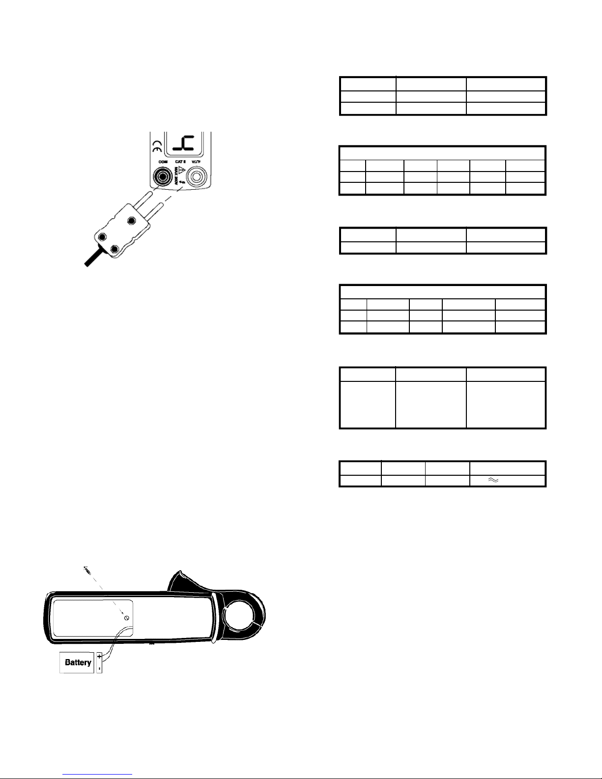
3. Remove the battery cover screw (Fig. 4).
4. Remove the battery cover.
5. Remove the depleted battery.
6. Insert a fresh 9V NEDA1604, IEC6F22 Battery, observe polarity
markings in the battery compartment.
7. Replace the battery cover.
8. Replace and secure the battery cover screw.
9. Resume normal use of the instrument.
Specifications
1. DC current
2. AC current
3. DC Voltage
(Input impedance 10mΩ)
4. AC Voltage
5. Temperature
(K-Type thermocouple)
6. Resistance
Environmental operating conditions
This clamp meter was designed to be used in temperature and
humidity that remains within the range of 60˚ to 90˚F and 30 to 85%
Relative Humidity (RH). Excessive temperatures (hot or cold) or
excessive humidity can cause the meter to give erroneous readings.
If the humidity raises to the point of causing condensation on the
ACM6000, the meter can become dangerous to use and can give
erroneous readings. Most test equipment in use today use sensitive
digital electrical components. These components are extremely
sensitive to heat and humidity.
NOTE: Whenever the meter undergoes a rapid or ex t r eme change of
t e m p e r a t u r e or humidity, it should be left on for about 5 minutes to
allow the internal tempera t u re to stabilize. This will ensure that your
m e a s u r ements are as accurate as possible.
ATA1 Temp
Probe Adapter
(Fig 3)
Battery Compartment
(Fig 4)
Range Resistance Accuracy
20A 10mA ±3.5% ±6 digits
200A 100mA ±3.5% ±3 digits
Accuracy
Range Resolution 50-60Hz 60-100Hz 100-400Hz 100-400Hz
20A 10mA ± 3 % ± 4 d g t s ± 3 % ± 7 d gt s ± 3 % ± 10 d g t s ± 3 % ± 1 0 d g t s
20 0 A 20 0 m A ± 3 % ± 4 d g t s ± 3 % ± 7 d g t s ± 3 % ± 10 d g t s ± 3 % ± 10 d g t s
Range Resolution Accuracy
200V 0.1V ±1% ±2 digits
Accuracy
Range Resolution 50-60Hz 60-400Hz 400-1000Hz
200V 0.1V ±1.5% ±2.0%±10dgts ±3.0%
±3dgts ±25dgts
Range Resolution Accuracy
40˚F 1˚F ±3% ±6dgts(<302˚F)
to 1000˚F ±3%(>302˚F)
at 50-90˚F ambient
Temperature
Range Resistance Accuracy Continuity Tone
2000Ω 1Ω ±1%±2dgts <25Ω
Page 11

ACM6000-MAN P. 10
Standard and Optional Accessories
Standard
Soft carrying case . . . . . . . . . . . . . . . . . . . . . . . . . . . . . .ACM6100P
Standard test lead . . . . . . . . . . . . . . . . . . . . . . . . . . . . . .ATL55
Temperature probe . . . . . . . . . . . . . . . . . . . . . . . . . . . . .ATA1/ATH2329
Optional
Rigid temperature probes with handles
Surface probe . . . . . . . . . . . . . . . . . . . . . . . . . . . . . .ATH2336
Liquid/Immersion probe . . . . . . . . . . . . . . . . . . . . .ATH2338
Air/Gas probe . . . . . . . . . . . . . . . . . . . . . . . . . . . . . .ATH2350
Screw on Alligator ends . . . . . . . . . . . . . . . . . . . . . . . . .AAC3
Extended test leads
7.5” leads . . . . . . . . . . . . . . . . . . . . . . . . . . . . . . . . . .ADL7100A107
11.5” leads . . . . . . . . . . . . . . . . . . . . . . . . . . . . . . . . .ADL7100A108
Premium silicon test leads . . . . . . . . . . . . . . . . . . . . . . .ATL300
Page 12

Limited Warranty
The ACM6000 is warranted to be free from defects in materials and workmanship for a period
of one year from the date of purchase. If within the warra n ty period your instrument should
become inoperative from such defects, the unit will be repaired or replaced at UEi’s option.
This warra n ty covers normal use and does not cover damage which occurs in shipment or
failure which results from alteration, tampering, accident, misuse, abuse, neglect or improper
maintenance. Batteries and consequential damage resulting from failed batteries are not
covered by warra n ty.
Any implied warranties, including but not limited to implied warranties of merchantability
and fitness for a particular purpose, are limited to the express warranty. UEi shall not be
liable for loss of use of the instrument or other incidental or consequential damages,
expenses, or economic loss, or for any claim or claims for such damage, expenses or
economic loss. A purchase receipt or other proof of original purchase date will be required
before warra n ty repairs will be rendered. Instruments out of warra n ty will be repaired (when
r e p a i r able) for a service charge. Return the unit postage paid and insured to:
1-800-547-5740 • FAX: (503) 643-6322
Service: (800) 308-7709
www.ueiautomotive.com • Email: info@ueiautomotive.com
This warranty gives you specific legal rights. You may also have other rights which vary from
state to state.
ACM6000
Low Amp Clamp-On DMM
Copyright © 2004 UEi Automotive ACM6000-MAN 4/04
 Loading...