

UDP Technology IPX3702HD-5314 Installation Manual

IPX3702HD-5314
Installation Guide
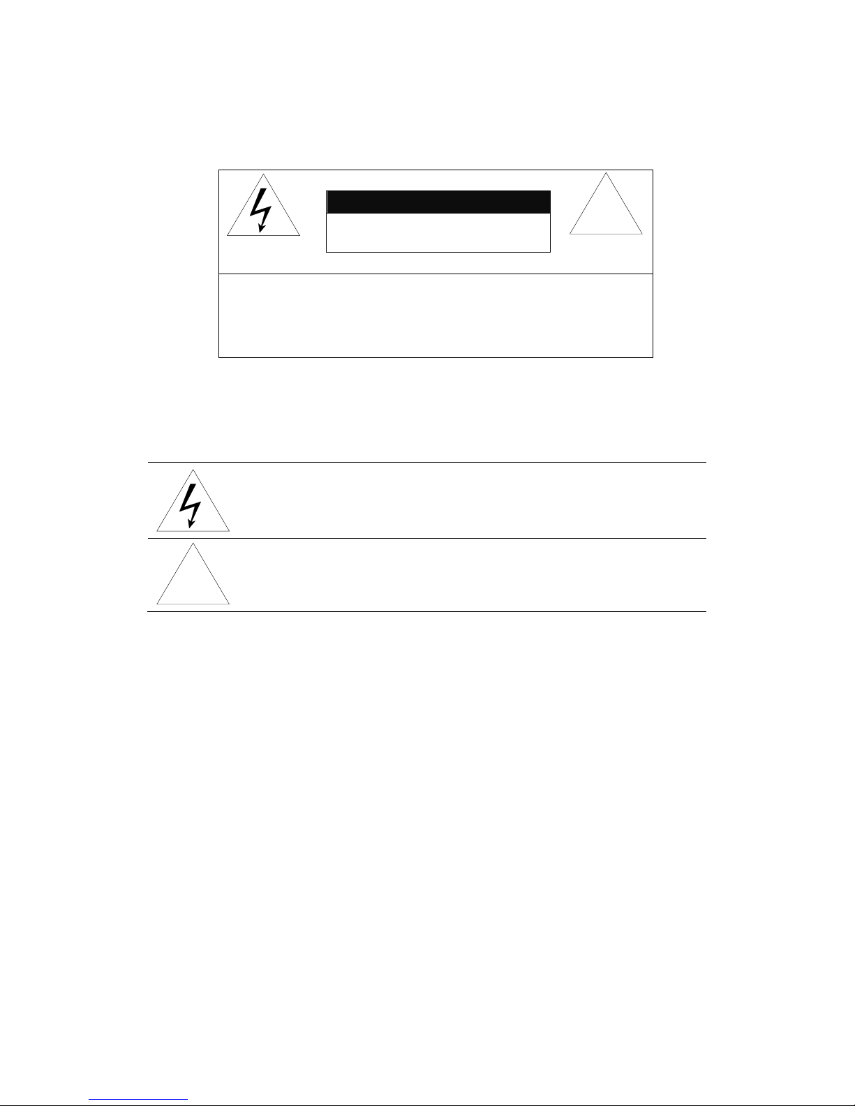
INFORMATION TO USER
CAUTION
RISK OF ELECTRIC SHOCK,
DO NOT OPEN
!
CAUTION: TO REDUCE THE RISK OF ELECTRIC SHOCK,
DO NOT REMOVE COVER (OR BACK).
CONTACT QUALIFIED SERVICE PERSONNEL FOR INTERNAL PARTS.
This symbol is intended to alert the user the presence of un-insulated
“dangerous voltage” within the product’s enclosure, which may be sufficient
magnitude to constitute a electric shock risk to persons.
!
This symbol is intended to alert the user the presence of important operating
and maintenance (servicing) instructions within the guide manual.

IPX/IPN Series Installation Guide
01A.01 3
Table of Contents
1. FEATURES ............................................................................................................. 4
2. PACKAGE CONTENTS............................................................................................. 5
3. PART NAMES ........................................................................................................ 6
4. INSTALLATION ...................................................................................................... 7
4.1. Installation Template ......................................................................................................... 8
4.2. Setting the Lens Position .................................................................................................... 9
4.3. Setting the Image Attribute ............................................................................................... 9
5. CONNECTIONS .................................................................................................... 10
6. CONFIGURATION ................................................................................................ 12
6.1.Set up network environment ............................................................................................ 12
6.1.1. Generic IP Environment ............................................................................................ 12
6.1.2. Custom IP Environment............................................................................................. 13
6.2. View video on web page .................................................................................................. 14
6.2.1. View video using IPAdmin Tool ................................................................................. 15
6.3. Reset ................................................................................................................................. 16
6.4. Factory Default ................................................................................................................. 16
APPENDIX (A): SPECIFICATIONS .............................................................................. 17
Summary ................................................................................................................................. 17
Electrical Characteristics ......................................................................................................... 18
Environment Condition ........................................................................................................... 18
Mechanical Condition ............................................................................................................. 18
APPENDIX (B): POWER OVER ETHERNET ................................................................. 19
PoE compatibility .................................................................................................................... 19
Power classification ................................................................................................................. 19
APPENDIX (C): DIMENSIONS ................................................................................... 20
APPENDIX (D): HEXADECIMAL-DECIMAL CONVERSION TABLE ................................. 21
REVISION HISTORY ................................................................................................. 22

IPX/IPN Series Installation Guide
01A.01 4
1. FEATURES
Camera
• Full HD outdoor fixed dome IP camera (Vandal proof)
• High quality compression in real time streaming
• 1/2.7” High Quality CMOS Image Sensor
• True Day / Night (ICR)
• Remote Zoom/Focus Control(One Click AF)
Streaming
• Dual streaming mode
• De-interlacing on DSP
• Burnt-in text supported
• Unicast/Multicast supported
Video/Audio
• Video compression: H.264/MJPEG, 25/30FPS@1080p(PAL/NTSC)
• Audio compression: G.711(µLaw, aLaw)/PCM
• Analog video out for external monitors
• Video motion detection supported
• Two-way mono audio supported
Network
• RTSP/ HTTP protocol supported
• 10/100 Base-T Ethernet
Additional Features
• Micro SD card support
• PoE support
• Built-in Video Content Analysis
• Internal fan/heater
• IP66 certified
• SDK (Software Development Kit) provided
IPX/IPN Series Installation Guide
01A.01 5
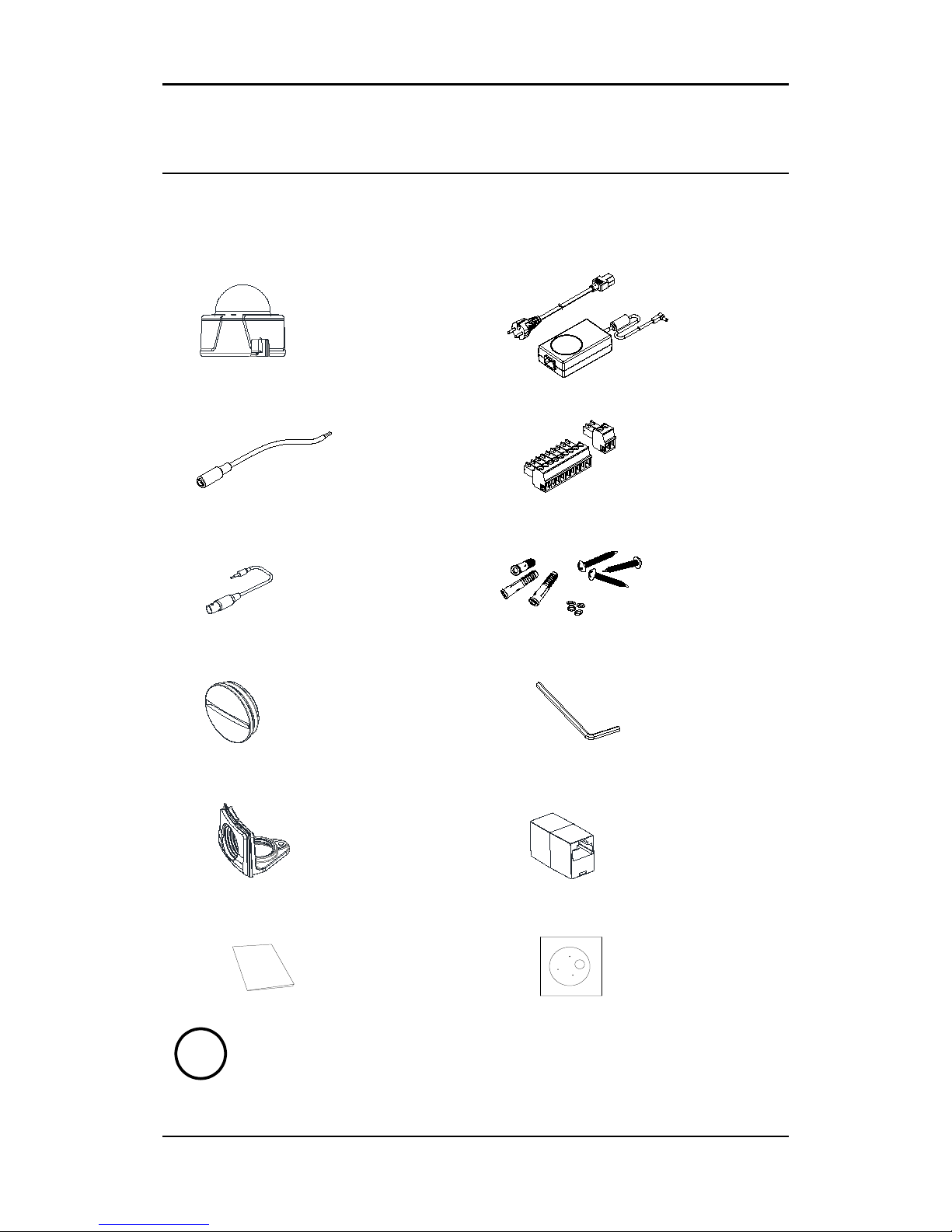
2. PACKAGE CONTENTS
Unpack carefully and handle the equipment with care. The packaging contains:
Camera
DC power adaptor
DC jack cable
8-pin and 2-pin terminal block
S-Video jack to 3.5mm plug
Screws and anchors
Side plug
Hex wrench driver
Side cover
RJ45 coupler
Quick installation guide
Installation template
Note
i
The package contents are subject to change without prior notice.
IPX/IPN Series Installation Guide
01A.01 6
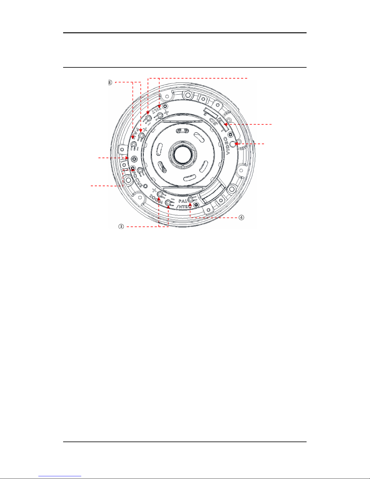
3. PART NAMES
① Rest button
The reset button can be used for restarting the device or resetting it to Factory Default.
② Focus buttons
Use the buttons to manually/automatically determine correct focus.
③ Zoom In/Out buttons
Use the buttons for camera to cover the wide field of view or to concentrate narrow field of view.
④ PAL/NTSC button
Pressing the button cycles through PAL, NTSC, and no video output mode: No video output -> PAL->NTSC
⑤ Video stereo jack connector
Connector for 3.5mm video jack plug.
⑥ MicroSD
SD card supports up to 32GB
⑦ Tilt buttons
Use the buttons to control rotation of the lens in a vertical plane.
⑧ Pan buttons
Use the buttons to control rotation of the lens in a horizontal plane.
②
③
⑤
* Models and their appearance are subject to change without any prior notice.
④ ⑧ ①
Top View
⑦
⑥
IPX/IPN Series Installation Guide
01A.01 7
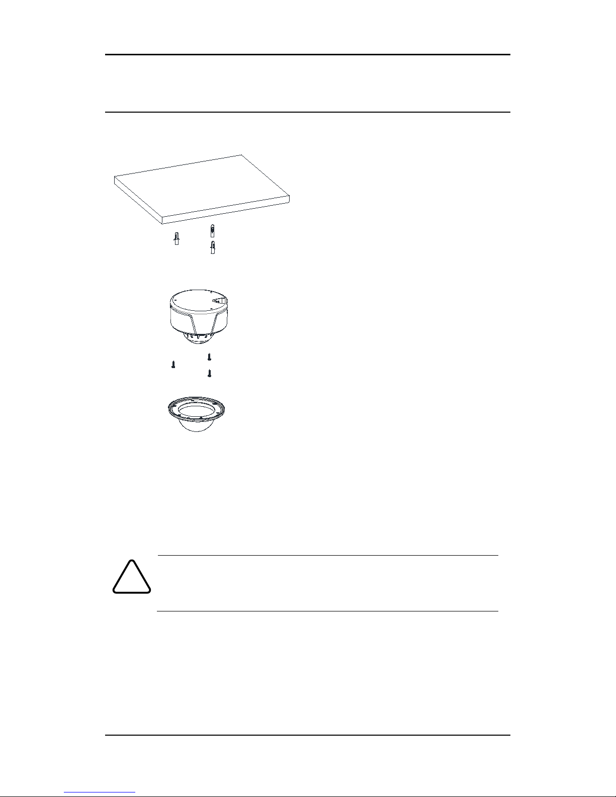
4. INSTALLATION
1) Place the installation template (paper) that
is included in the package on the desired
installation surface.
2) Drill three holes in correct positions based
on the template paper, and insert anchor
blocks into the holes.
3) When placing
the camera body to the
installation surface,
match three alignment
holes with three anchor blocks.
4) Tighten the surface anchor studs.
5) Connect all the r
equired cables to the
camera.
6)
Adjust the lens position. Detailed
information can be found in
4.2. Setting the
Lens Position.
7) Place the dome cover on the main body of
the camera. Dome cover has three alignment
holes that match camera body’
s alignment
holes.
8) Once properly placed, insert hex screws
into the three holes of the body and tighten
them up with hex wrench driver.
Caution
!
To prevent products from damaging, place the camera on stable and non-vibrat
ing surfaces. If the stability is in doubt, consult with safety personnel for reinfor
cements, and then proceed with the installation.
 Loading...