

UDP Technology IPN1202HD Installation Manual
01A.03 UDP Technology Ltd. i
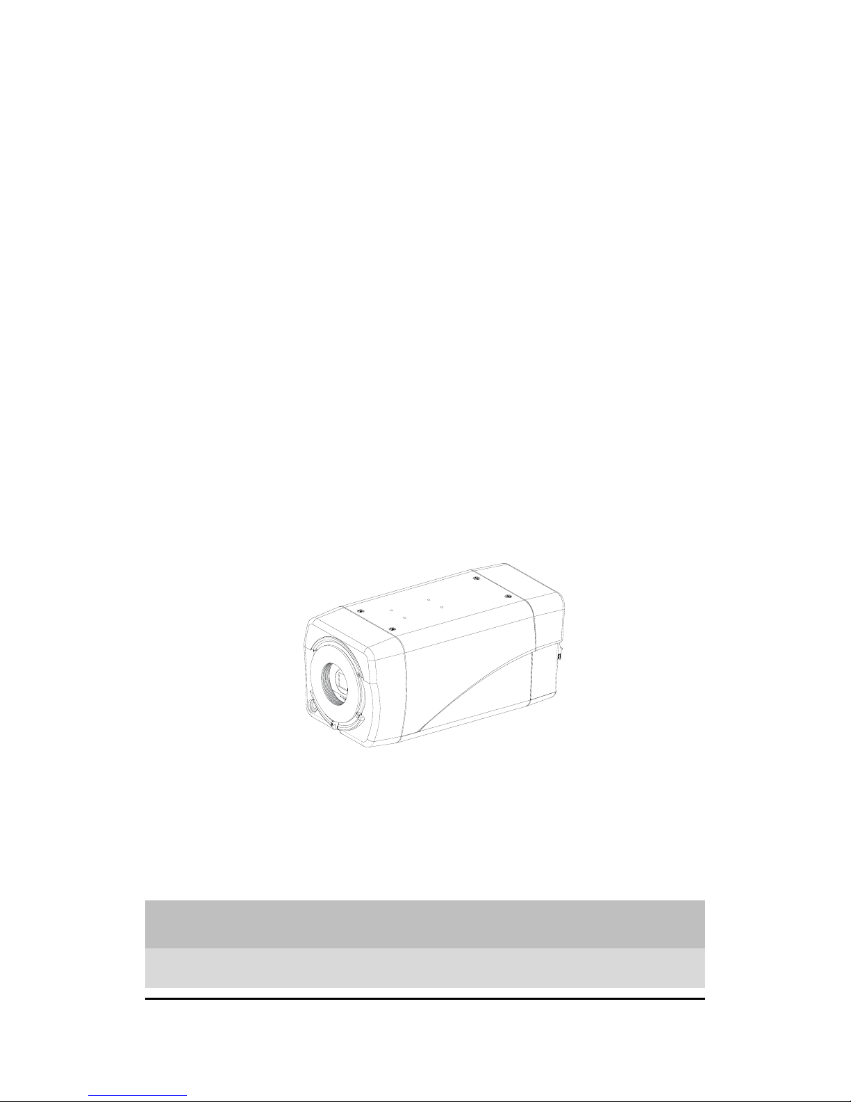
IPN1202HD
Installation Guide
IPN Series IPN1202HD-5241 Installation Guide
01A.03 UDP Technology Ltd. 2
INFORMATION TO USER
CAUTION
RISK OF ELECTRIC SHOCK,
DO NOT OPEN
!
CAUTION: TO REDUCE THE RISK OF ELECTRIC SHOCK,
DO NOT REMOVE THE DEVICE COVER (OR BACK).
CONTACT QUALIFIED SERVICE PERSONNEL FOR INTERNAL PART
SERVICES.
This symbol is intended to alert the user the presence of un-insulated
“dangerous voltage” within the product’s enclosure, which may be sufficient
magnitude to constitute a electric shock risk to persons.
!
This symbol is intended to alert the user the presence of important operating
and maintenance (servicing) instructions within the guide manual

IPN Series IPN1202HD-5241 Installation Guide
01A.03 UDP Technology Ltd. 3
Table of Contents
1. FEATURES ............................................................................................................. 4
2. PACKAGE CONTENTS............................................................................................. 5
3. PART NAMES ........................................................................................................ 6
3.1. Rear View ........................................................................................................................... 6
3.2. Side View ............................................................................................................................ 6
3.3. Front View .......................................................................................................................... 6
4. INSTALLATION ...................................................................................................... 8
4.1. Installing a Lens .................................................................................................................. 8
4.2. Installing the Mounting Adaptor ........................................................................................ 9
4.3. Connecting Cables .............................................................................................................. 9
4.4. Setting the Image Attribute ............................................................................................. 12
5. CONFIGURATION ................................................................................................ 13
5.1. Set up network environment ........................................................................................... 13
5.1.1. Generic IP Environment ............................................................................................ 13
5.1.2. Custom IP Environment............................................................................................. 13
5.2. View video on web page .................................................................................................. 14
5.2.1. View video using IPAdmin Tool ................................................................................. 16
5.3. Reset ................................................................................................................................. 17
5.4. Factory Default ................................................................................................................. 17
APPENDIX (A): SPECIFICATIONS .............................................................................. 18
Summary ................................................................................................................................. 18
Electrical Characteristics ......................................................................................................... 19
Environment Condition ........................................................................................................... 19
Mechanical Condition ............................................................................................................. 19
APPENDIX (B): POWER OVER ETHERNET ................................................................. 20
APPENDIX (C): DIMENSIONS ................................................................................... 21
APPENDIX (D): HEXADECIMAL-DECIMAL CONVERSION TABLE ................................. 22
REVISION HISTORY ................................................................................................. 23

IPN Series IPN1202HD-5241 Installation Guide
01A.03 UDP Technology Ltd. 4
1. FEATURES
Camera
• Box type full-HD IP camera
• 1/2.7” 1080p CMOS Image Sensor
• 3.1~8 mm, F1.2, F1.2 DC auto iris lens, CS mount
Streaming
• Dual streaming mode
• Burnt-in text support
• Unicast/Multicast support
Video/Audio
• Video compression: H.264/MJPEG, 25/30FPS@1080p(PAL/NTSC)
• Audio compression: G.711(µLaw, aLaw)/PCM
• Analog video out for external monitors
• Video motion detection supported
• Two-way mono audio supported
Network
• RTSP/ HTTP protocol support
• 10/100 Base-T Ethernet
Additional Features
• RS-485 support
• MicroSD card slot support (Local storage)
• PoE support
• Built-in Video Content Analysis
• Burnt-in text support
• SDK (Software Development Kit) support

IPN Series IPN1202HD-5241 Installation Guide
01A.03 UDP Technology Ltd. 5
2. PACKAGE CONTENTS
The package contains main camera, DC power adaptor, DC jack cable, camera lens, terminal
block, power adaptor jack, screws, mounting adaptor, clamping core, and quick installation
guide. Unpack carefully and handle the equipment with care.
Camera
DC power adaptor
Lens
Terminal block
Power adaptor jack
Screws
Adaptor for mounting the camera
Quick installation guide
Clamping core
To prevent electromagnetic interference
Note
i
The above contents are subject to change without prior notice.
IPN Series IPN1202HD-5241 Installation Guide
01A.03 UDP Technology Ltd. 6
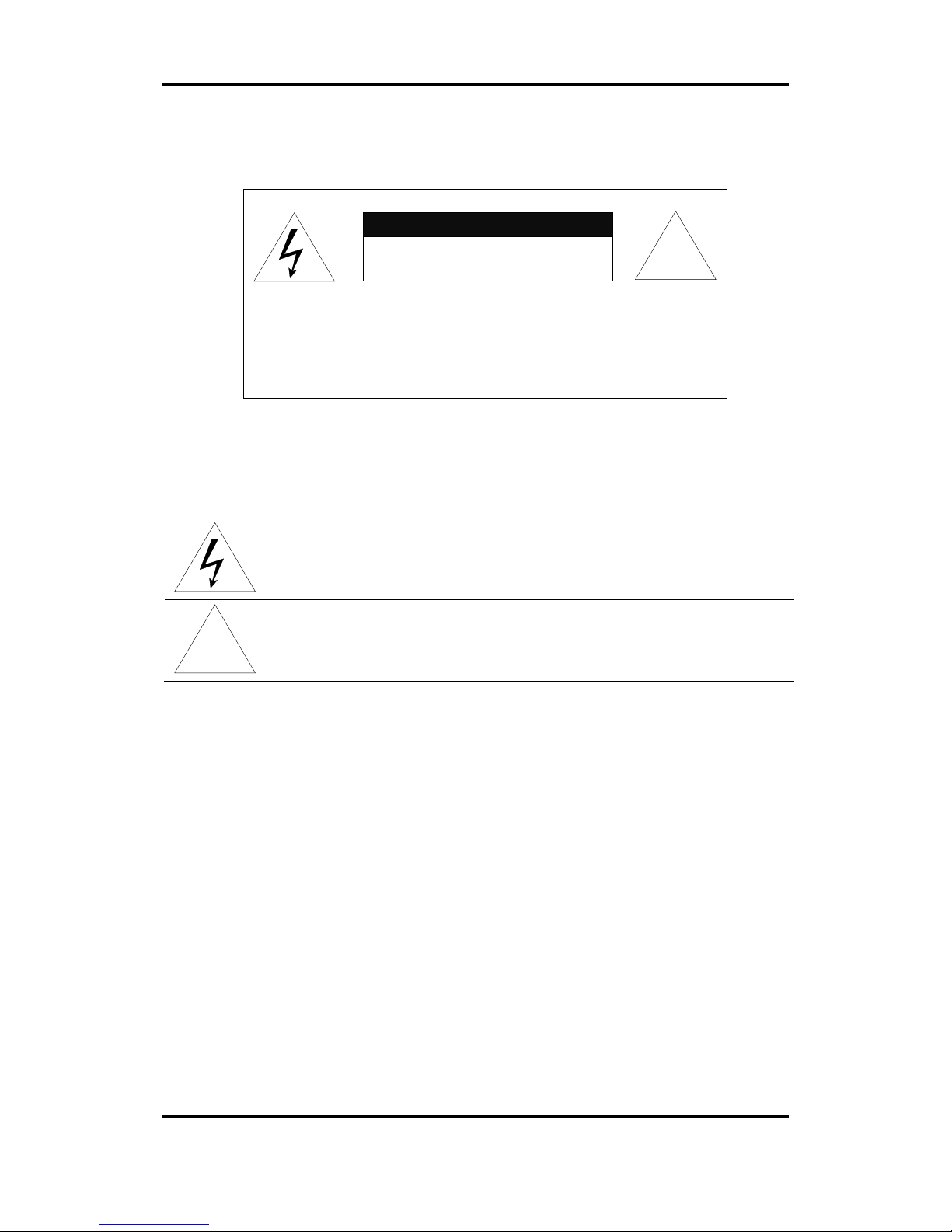
3. PART NAMES
3.1. Rear View
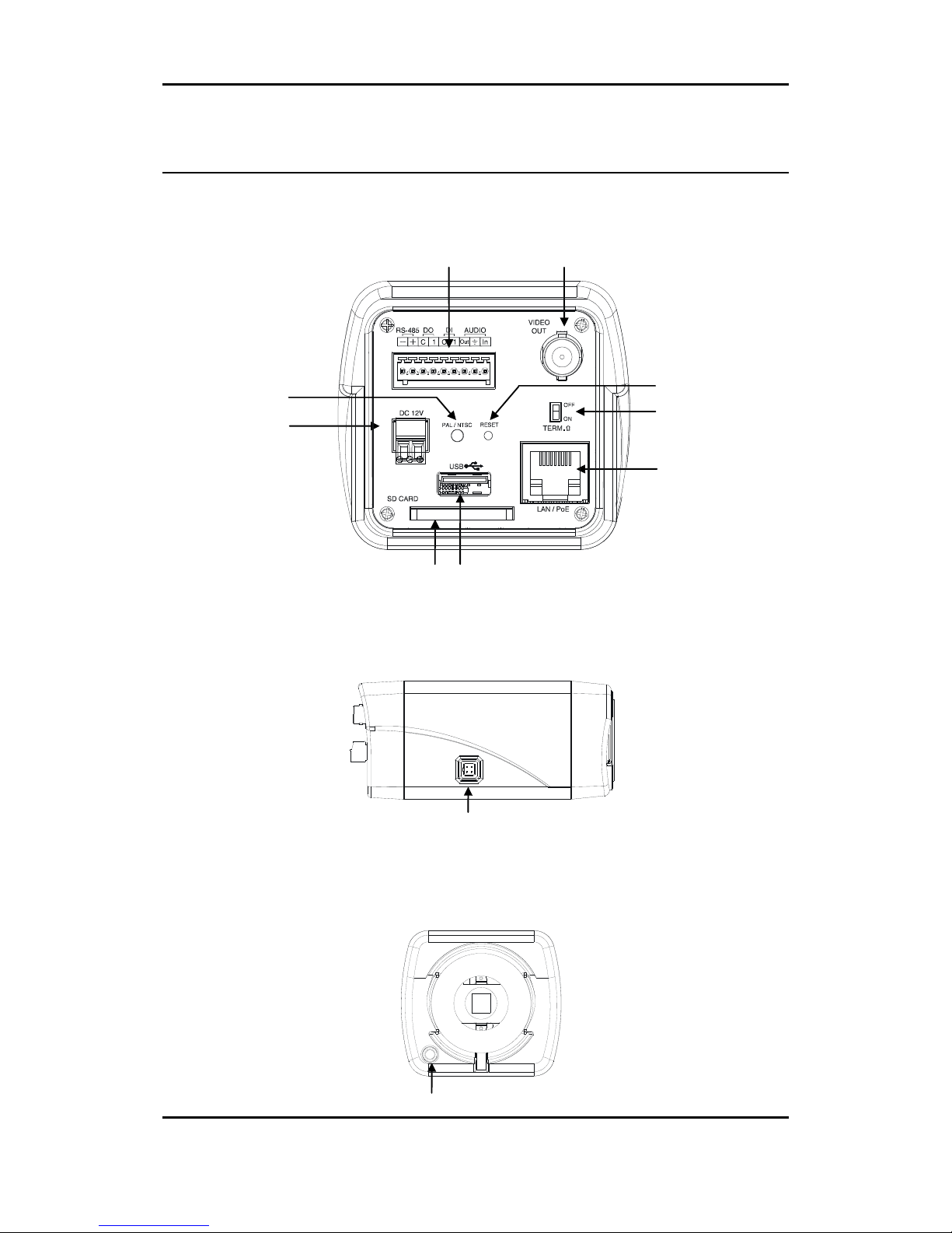
3.2. Side View
3.3. Front View
○11
○6
○5
○1
○2
○
4
③
○7
⑧
○9
⑩

IPN Series IPN1202HD-5241 Installation Guide
01A.03 UDP Technology Ltd. 7
①
Power Adaptor Connect
The camera requires DC 12V for power supply. Refer to the section “4.3. Connecting Cables”
for more specific information
② PAL/NTSC button
Press the PAL/NTSC button to set video output as PAL or NTSC. The default is no video output.
Each time pressing the button cycles through PAL, NTSC, and no video output mode: No video
output -> PAL->NTSC
③
11 pin terminal block for D/I, D/O, audio, and serial communication
Refer to the section “4.3. Connecting Cables” for more specific information.
④ Analog Video Out Connector
Use BNC cable (not supplied) to connect between the camera and monitor to verify image
focuses at the installation site. Users must cycle through button (no video output -> PAL ->
NTSC) to select the video output. Once the PAL/NTSC button is pressed, the video displays for
3 minutes before returns back to ‘no video output’ status.
⑤ Reset Button
Use the reset button to restart or reset the camera back to factory default settings. Refer to
the section “5.3. Reset” for more specific information.
⑥ RS-485 Termination Switch (120ohm)
Select ON or OFF for RS-485 termination register. The default is off.
⑦ Network Port
Use the RJ45 LAN connector for connecting the camera to network or supplying PoE power.
⑧ USB 2.0 Port
Plug an USB flash drive or wireless LAN device.
⑨ SD Card Slot
Supports memory cards up to 32GB.
⑩ Auto Iris Lens Connector
The 4-pin connector for an auto iris camera lens.
⑪ Light Sensor
The light sensor is used to detect the level of ambient light detect intensity of light. The sensor
should not be blocked by cable or any other objects.
 Loading...