

UDP Technology IPE3500M Installation Manual
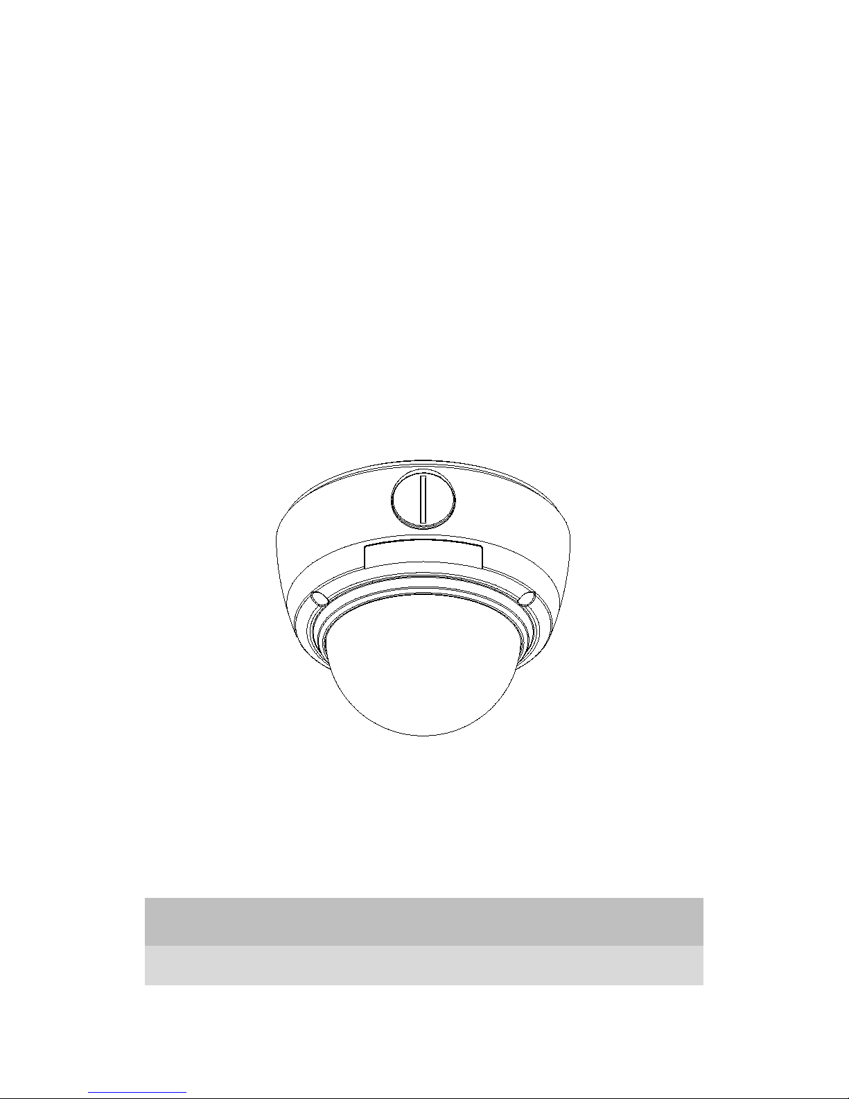
IPE3500M
Installation Guide
INFORMATION TO USER
CAUTION
RISK OF ELECTRIC SHOCK,
DO NOT OPEN
!
CAUTION: TO REDUCE THE RISK OF ELECTRIC SHOCK,
DO NOT REMOVE COVER (OR BACK).
NO USER SERVICEABLE PARTS INSIDE.
REFER SERVICING TO QUALIFIED SEERIVCE PERSONEL.
This symbol is intended to alert the user to the presence of un-insulated
“dangerous voltage” within the product’s enclosure that may be of sufficient
magnitude to constitute a risk of electric shock to persons.
!
This symbol is intended to alert the user to the presence of important
operating
and maintenance (servicing) instructions in the literature
accompanying the appliance.

NVC/IPE Series IPE3500M Installation Guide
02A.07 UDP Technology Ltd. 3
Table of Contents
1. FEATURES ............................................................................................................. 4
2. PACKAGE CONTENTS............................................................................................. 5
3. PART NAMES ........................................................................................................ 6
3.1.Internal View ....................................................................................................................... 6
4. INSTALLATION ...................................................................................................... 8
4.1. Installation Template ......................................................................................................... 9
4.2. Manual adjustment for 3-axis movements ...................................................................... 10
4.3. Setting the Image Attribute ............................................................................................. 10
5. CONNECTIONS .................................................................................................... 11
5.1.Connectors ........................................................................................................................ 11
6. CONFIGURATION ................................................................................................ 13
6.1.Set up network environment ............................................................................................ 13
6.2. View video on web page .................................................................................................. 13
6.2.1. View video using IPAdmin Tool ................................................................................. 13
6.2.2.View video using IP address ....................................................................................... 15
6.3. Reset ................................................................................................................................. 15
6.4. Factory Default ................................................................................................................. 15
APPENDIX (A): SPECIFICATIONS .............................................................................. 16
Summary ................................................................................................................................. 16
Resolutions per Codec Frame rate .......................................................................................... 17
Environment Condition ........................................................................................................... 17
Mechanical Condition ............................................................................................................. 17
APPENDIX (B): POWER OVER ETHERNET ................................................................. 19
PoE compatibility .................................................................................................................... 19
Power classification ................................................................................................................. 19
APPENDIX (C): DIMENSIONS ................................................................................... 20
APPENDIX (D): HEXADECIMAL-DECIMAL CONVERSION TABLE ................................. 21
REVISION HISTORY ................................................................................................. 22

NVC/IPE Series IPE3500M Installation Guide
02A.07 UDP Technology Ltd. 4
1. FEATURES
Camera
• Indoor/Outdoor Fixed Dome IP Camera (Vandal Proof)
• High Quality Compression in real time streaming
• Aptina (Micron) 1/3.2” (4:3) CMOS 2M
• Digital Day & Night
• Improvement of color rolling suppression
Streaming
• Dual streaming mode (such as different codec/resolution/bit rate and so on.)
• Burnt-in text supported
• Unicast/Multicast supported
Video/Audio
• Video compression: H.264/MPEG/MJPEG, 25/30FPS@D1(PAL/NTSC)
• Audio compression: G.711(µLaw, aLaw)/PCM
• Video Motion Detection supported
• Two-way mono audio supported
Network
• RTSP/ HTTP protocol supported
• 10/100 Base-T Ethernet
Additional Features
• RS-485 supported
• Micro SD card supported
• PoE supported
• Built-in Video Content Analysis
• OSD supported
• SDK (Software Development Kit) provided
VCA (Video Content Analysis)
• VCA Presence (Included as basic)
• VCA Surveillance (Optional)
NVC/IPE Series IPE3500M Installation Guide
02A.07 UDP Technology Ltd. 5
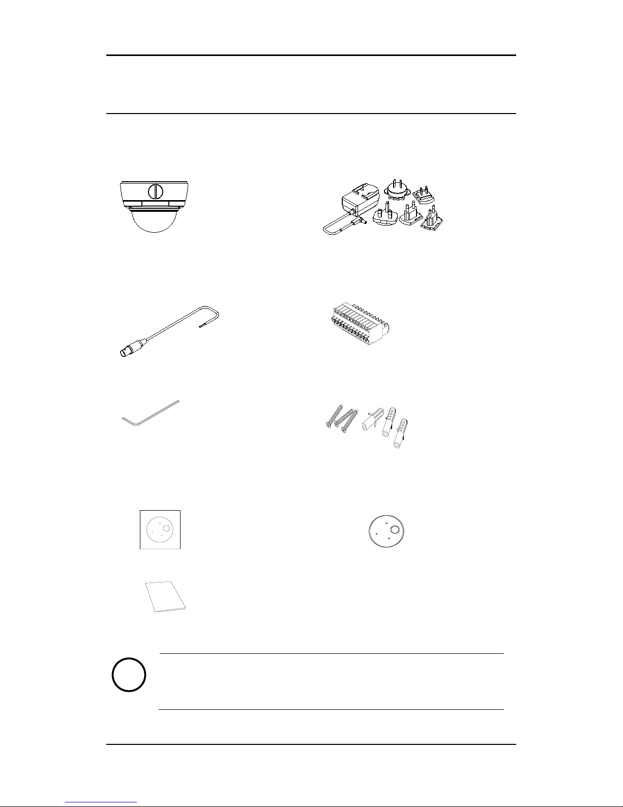
2. PACKAGE CONTENTS
Unpack carefully and handle the equipment with care. The packaging contains:
Camera
DC power adaptor
Power extension cable
11 Pin terminal block
Hex wrench driver
Screws and Anchor blocks
Installation Template
Surface Cushion
(for protection against dust)
Quick Installation Guide
Note
i
The above contents are subject to change without prior notice.

NVC/IPE Series IPE3500M Installation Guide
02A.07 UDP Technology Ltd. 6
3. PART NAMES
3.1.Internal View
① 11 pin terminal block for D/I, D/O, audio, and serial communication
11 pin terminal block for D/I, D/O, Audio in /Out and serial communication. Refer to the
section “5.1.Connectors” for more specific information.
② Reset
Reset switch is used for restarting or resetting the camera to Factory Default (FD). Refer to the
section “6.3. Reset” for more specific information.
③ Extension cable Socket
It is a socket for LAN and power connector
④ Micro SD Card Socket
It is a memory card slot for external storage.
⑤ LAN Connector (Ethernet)
This is a RJ45 LAN connector for 10/100 Base-T Ethernet. This socket can also be used to power
the camera via PoE (Optional).
①
②
③
④
* Models herein and their appearance
are subject to change without any prior
notice.
⑥ ⑤

NVC/IPE Series IPE3500M Installation Guide
02A.07 UDP Technology Ltd. 7
This LED lights up as orange and turns green when the encoder is powered on.
LED operation setting:
For the factory default setting, LED 2 blinks for the heartbeat and LED 1 turns on for video
signal. To change its setting, refer to the section 4.5.11. LED Setting of the NVC Web Page
User’s Manual.
⑥ Power Adaptor Connector (DC 12V)
The camera needs a DC 12V 1A adapter for power supply.
LED1 LED2
 Loading...