

Page 1

IPC4100
Hardware Manual
(IPC4100A-25D, IPC4100A-23)
Page 2

IPC 4100 Hardware Manual
Table of Contents
1. INTRODUCTION ................................................................................................................... 3
2. Product Description ................................................................................................................ 4
2.1. Specifications .................................................................................................................. 4
3. INSTALLATION & CONFIGURATION ............................................................................. 6
3.1. Package Contents ............................................................................................................ 6
3.2. Part List ........................................................................................................................... 7
3.3. Basic Configuration of IPC4100 ..................................................................................... 8
3.4. DIP Switch Setting ........................................................................................................ 10
3.5. Setting Address(ID) of Dome Camera .......................................................................... 12
3.6. Connecting Wiring ........................................................................................................ 14
4. Operation Description........................................................................................................... 17
4.1. Factory Default Settings................................................................................................ 17
4.2. Rebooting ...................................................................................................................... 17
4.3. On Screen Menu ........................................................................................................... 17
5. TECHNICAL SPECIFICATIONS ...................................................................................... 18
6. DIMENSIONS ....................................................................................................................... 20
APPENDIX A - The List of GLB(Short) Key ......................................................................... 21
APPENDIX B - TROUBLE SHOOTING ............................................................................... 23
APPENDIX C - OPTIONAL ITEMS ...................................................................................... 24
1. HOUSING & ACCESSORY ........................................................................................... 24
Revision history ......................................................................................................................... 29
C UDP Co., Ltd. 2
Page 3

IPC4100 Hardware Manual
1. INTRODUCTION
This IPC4100 compress video/audio data and transmit the compressed video/audio data through
the network in real time. IPC4100 provides a high quality video image with a limited bandwidth
and storage capacity. These products are ideally suited for a wide range of surveillance and
remote monitoring applications. Main features are highlighted below.
Main features
• High Quality Compression in real time streaming
• NVE provides high quality MPEG-4 and MJPEG encoding at D1 in real time. Main
features
Network
• RTP/RTSP and unicast/multicast are supported.
Streaming
• IPC4100 supports de-interlacing by hardware.
Video/Audio
• Loop out is supported
• IPC4100 supports two ways audio
Transmits to client - G.711 by software
Receives from client - one digital audio
Camera
• 25X Auto Focus Optical Zoom Lens, 10X Digital Zoom (Total 250X Zoom Ratio)
• Day / Night with removable IR Cut Filter (Auto ICR)
• DSS (Digital Slow Shutter) : (IC4100A-25D Only)
• Minimized Vibration at slow speed
• Auto Flip 180 Dome Rotation
• Turbo speed is maximum 430 per seconds
Additional Features
• Motion detection by hardware.
• On Screen Display (OSD) by hardware.
• RS-485 serial port
• RS-232C serial port for some devices like a POS terminal.
• IPC4100 supports built-in surge protection and lightning protection circuit.
SDK
• Four types (RTSP, UDA5, ActiveX, HTTP-API) are provided for application
development.
C UDP Co., Ltd. 3
Page 4

IPC4100 Hardware Manual
2. Product Description
2.1. Specifications
IPC4100 specification is shown as following Table
Network
IPC4100A-25D IPC4100A-23
Video Compression MPEG-4, JPEG
Resolution D1, 2CIF, CIF, QCIF
Compression FPS 25/30 fps @ D1
Audio Input/Output 1 / 1 ch
Compression PCM(software compression : G.711, uLaw)
Network 10/100 Base-T
RS-232C Supported
RS-485 / 422 Supported
De-interlacing Supported by hardware
Motion Detection Supported by hardware
OSD & Private
Region Masking
Supported by hardware
Video Stream Encryption AES
Protocol TCP,UDP,DHCP,HTTP,NTP,RTSP,RTP(Unicast,Multicast)
Camera
IPC4100A-25D IPC4100A-23
Pick Up Device
Sony ¼
”
Super HAD CCD
Effective Pixels
NTSC – 768(H) x 494 (V) / PAL – 752 (H) x 582(V)
Television System 2 : 1 Interlace
Horizontal Resolution
NTSC – 470 TVL / PAL – 460 TVL
Minimum Illumination
1.0 Lux (30 IRE)
Day / Night Off (Color)
1.0 Lux (30 IRE)
0.1 Lux (30 IRE)
Day / Night On (B & W)
0.01 Lux
Slow Shutter x 128 On
0.001 Lux (30 IRE)
Day / Night On (B & W) + DSS
Lens
25X Optical Day / Night 23 X Optical
F 1.6 f=3.8 ~ 95 mm F1.6 f=3 .8 ~ 87.4 mm
S/N Ratio 50 dB 49 dB
C UDP Co., Ltd. 4
Page 5

IPC4100 Hardware Manual
Dome
IPC4100A-25D IPC4100A-23
Pan Angle / Speed
360 Continuous Rotation, 0.1 ~90 / Sec
Turbo Speed : 430 / Sec
Preset Speed 360 / 430 /500 Selectable, Default 360 / Sec
Tilt Angle / Speed 0 ~ 94, 0.1 ~90 / sec (According to Zoom Ratio)
Camera ID 999
Home Default / Preset / Tour /Auto Scan /Patter Programmable
Preset 319 Position (16 Characters Input)
Auto Scan 8 Auto Scan
Guard Tour 8 Guard Tour (Preset, Pattern, Auto Scan, Tour Input)
Pattern 4 Pattern (240 Sec Memory)
Remote Control Network / RS-485, 422
Alarm Input 2 Inputs (NC/NO)
Alarm Output 1 Relay 24 VAC / 1 A (NC/NO)
Global Key Available
Self Monitoring Software Built-in
On Screen Display Camera ID, Pan / Tilt Angle, Flip, Zoom etc,
Material Aluminum / PC
Color Black
Dimensions 137.3 x 205 (D) mm
Weight 1,850 g
C UDP Co., Ltd. 5
Page 6

IPC4100 Hardware Manual
3. INSTALLATION & CONFIGURATION
3.1. Package Contents
The Package contains the following
IPC4100.------------------------------------------------------------------------- 1
Plastic Anchor ------------------------------------------------------------------ 3
Screws for Plastic Anchor ----------------------------------------------------- 3
Surface Mount Bracket Adapter---------------------------------------------- 1
LAN Cable (Cross Type 1.5m) ----------------------------------------------- 1
7 Pin Terminal Block ---------------------------------------------------------- 1
3 Pin IPC Cable ---------------------------------------------------------------- 1
6 Pin IPC Cable ---------------------------------------------------------------- 1
C UDP Co., Ltd. 6
Page 7
IPC4100 Hardware Manual
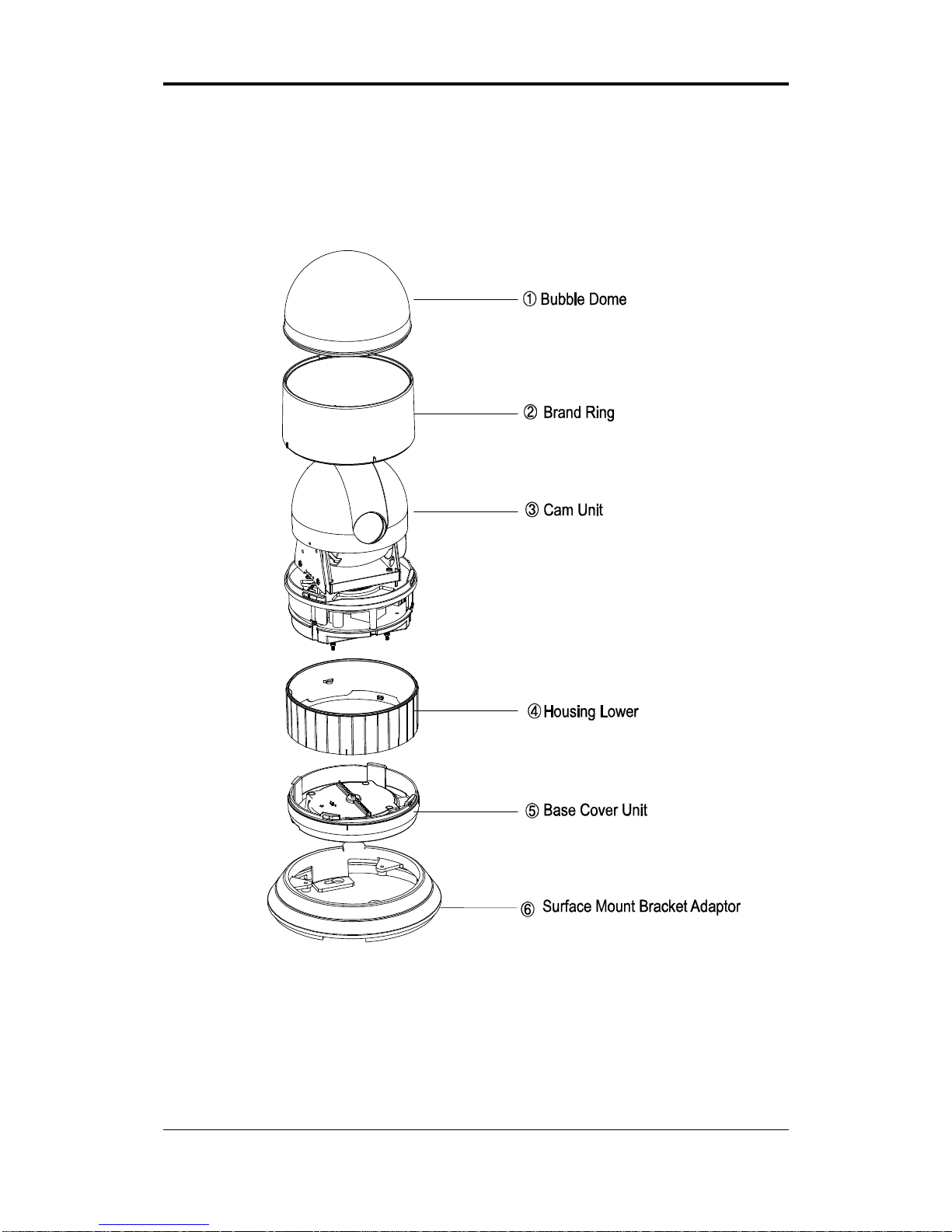
3.2. Part List
Figure 1. Part List
C UDP Co., Ltd. 7
Page 8
IPC4100 Hardware Manual
C UDP Co., Ltd. 8
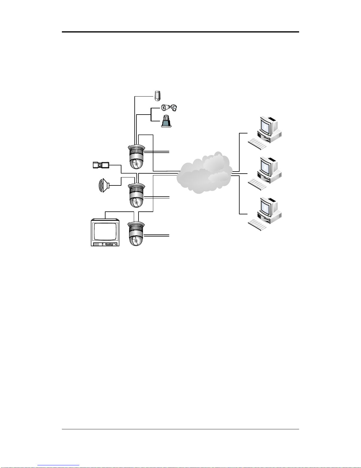
3.3. Basic Configuration of IPC4100
Figure 2. Basic Installation Configuration
The dome camera is for use in surface mounting applications and the mounting surface should
be capable of supporting loads up to 10 lb(4.5Kg)
The dome camera’s base should be attached to a structural object, such as a hard wood, wall
stud or ceiling rafter that supports the weight of the dome camera.
Sesor
Siren
Flashing Light
Analog Monitor
MIC
Amp Speaker
MIC4DVR
Alarm Input
Up to 2
AC 24V
Power supply
AC 24V
Power supply
AC 24V
Power supply
Alarm Output
Up to 2
Client PC
Ethernet Network
Page 9
IPC4100 Hardware Manual
C UDP Co., Ltd. 9
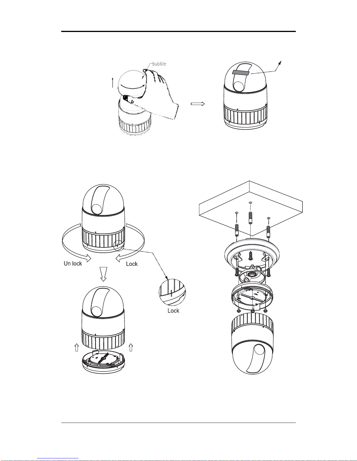
Figure 3. Bubble Dome
Figure 4. Installation of ceiling mount
The dome camera must be installed by qualified service personnel in accordance with all local
and federal electrical and building codes. The system should be installed according to Figure 2
hrough Figure 10.
Page 10

IPC4100 Hardware Manual
C UDP Co., Ltd. 10
Figure 5. Layout of Switches
3.4. DIP Switch Setting
ith a Cyber Scan joystick controller or if a dome camera is
controlled through the network, select Cyber Scan II Protocol and if Consult service personnel if
If a dome camera is to be installed w
a dome camera is installed with device other than a joystick.
Protocol Setting
Page 11

IPC4100 Hardware Manual
C UDP Co., Ltd. 11
Communication Speed
Communication T ype
System Type (Factory Use)
Figure 6. DIP Switch Setting
Termination Setting
8 FUNCTION
ON PAL
OFF NTSC
ON
8
NTSC/PAL
1 2 3 4 PROTOCOL
OFF OFF OFF OFF Cyber Scan I
OFF OFF OFF ON P-D Type
OFF OFF ON OFF P-P Type
OFF ON OFF OFF G-Speed Dome
ON OFF OFF OFF SNS Type
OFF ON OFF ON KAL Type
OFF ON ON OFF DEN Type
OFF ON ON ON BOS Type
ON OFF OFF OFF SAMS Type
ON OFF OFF ON SAE Type
ON OFF ON OFF Reserved
ON OFF ON ON Reserved
ON ON OFF OFF Reserved
ON ON OFF ON Reserved
ON ON ON OFF Reserved
ON ON ON ON Cyber Scan II
ON
1
234
Protocol
* Factory Mode : Cyber Scan II
5 6 BAUD RATE
OFF OFF 9600
OFF ON 4800
ON OFF 2400
ON ON 38400
ON
65
BaudRate
7 FUNCTION
ON RS-422
OFF RS-485
ON
7
RS-422/485
* Factory Mode : RS-485
Page 12

IPC4100 Hardware Manual
C UDP Co., Ltd. 12
The device which is connected at end of line, whether it be a dome camera or joystick controller,
he dome camera must be installed by qualified service personnel in accordance with all local
must have the cable for communication terminated by setting the appropriate DIP switch.
Without proper termination, there is potential for control signal errors. Total length of the
cable for communication should not exceed 1.2Km.
Figure 7. Setting Unit for Termination
T
and federal electrical and building codes. The system should be installed according to Figures 2
through 10.
Figure 8. Termination Diagram
3.5. Setting Address(ID) of Dome Camera
9 10 Function
ON ON Termination
OFF OFF N ot Terminated
ON
109
Termination
* Factory Mode : Not Terminated
Page 13

IPC4100 Hardware Manual
To prevent damage, each dome camera must have an unique address(ID). When installing
multiple dome cameras using a multiplexer, it is suggested that the dome camera address
matches the multiplexer port number.
DOME ID SW100 SW10 SW1
1 0 0 1
2 0 2
. . . .
999 9 9 9
- SW 100 : MSB(Most Significant Bit)
- SW 1 : LSB(Least Significant Bit)
Figure 9. Setting Address(ID) of Dome Camera
C UDP Co., Ltd. 13
Page 14

IPC4100 Hardware Manual
3.6. Connecting Wiring
ALARM INPUT
RS-232RS-42
2
I
N
1
I
N
2
G
N
D
R
x
T
x
G
N
D
T
R
X
+
T
R
X
-
T
X
+
T
X
-
RS-48
5
N
O
N
C
COM
Audi0 I
n
Audio Out
GND
ALARM
OUTPU
T
AUDIO
ETHERNE
T
RESET
I
N
1
I
N
2
G
N
D
R
x
T
x
G
N
D
T
R
X
+
T
R
X
-
T
X
+
T
X
-
G
N
D
A
U
D
I
O
O
u
t
A
U
D
I
O
I
n
C
O
M
NCN
O
RS-232RS-42
2
R
x
T
x
G
N
D
T
R
X
+
T
R
X
-
T
X
+
T
X
-
RS-48
5
Serial
communication
Video Output
Connector
1
2
Alarm Input
3
Alarm Output/Audio
4
ETHERNE
T
5
Power
6
Reset
S/W
7
Figure 10. Connecting Wiring
C UDP Co., Ltd. 14
Page 15

IPC4100 Hardware Manual
① 7 pin terminal block for serial communication
RS-232C Terminal Block is used for some devices such as POS terminal block.
Figure 11. RS-232C Connection
The RS-485 serial port consists of TRX+(RX+) and TRX-(RX-) as following Figure 12.
Figure 12. RS-485 Connection
The RS-422 serial port consists of TRX+(RX+), TRX-(RX-), TX+ and TX- as following Figure
13.
Figure 13. RS-422 Connection
② BNC connector for video loop out
C UDP Co., Ltd. 15
Page 16

IPC4100 Hardware Manual
Connect the video out (BNC) connector to the monitor or video input.
③ 3 pin terminal block for D/I
You can use external devices to signal the dome camera to react to events. Mechanical or
electrical switches can be wired to the IN(Alarm In) and GND(Ground) connectors.
GND(Ground)
Note : All the connectors marked GND are common.
Connect the ground side of the Alarm input to the GND connector.
④ 6 pin terminal block for D/O and audio
The dome camera can activate external devices such as buzzers or lights. Connect the device to
the NC(NO)(Alarm Out) and COM(Common) connectors.
⑤ LAN connector (Ethernet)
This is a RJ45 LAN connector for 10/100 Base-T Ethernet.
Figure 14. RJ45 LAN connector
⑥ Terminal block for the Power
Connect the power of AC 24V 850mA to the dome camera.
⑦ Reset Switch (Reset)
Reset switch is used for restarting NVE or resetting NVE as Factory Default (FD). Refer to ‘4.1.
Factory Default Settings’ for detailed procedures. (This function is not implemented yet)
C UDP Co., Ltd. 16
Page 17

IPC4100 Hardware Manual
4. Operation Description
4.1. Factory Default Settings
Factory default settings are as follows:
• IP address: 192.168.xx.yy (refer to 2.3 Serial Number / MAC Address)
• Mask: 255.255.0.0
• Gateway: 192.168.0.1
• User ID: root
• Password: pass
MAC address = 00-13-23-01-23-45 → IP address = 192.168.35.69
Convert the Hexadecimal number to Decimal number
Factory Default (FD) initialization procedure is as follows
1. Turn ON the power.
2. Press “Reset” button when Status LED at LAN connector start to blink very rapidly.
3. Release “Reset” button when Status LED at LAN connector is blinking slowly.
4.2. Rebooting
Reset can be carried out as follows:
1. Press Reset for 1 second.
When Reset function is activated, Status LED and Network LED at LAN connector will
blink together, twice. User may stop pressing Reset at this point.
2. When “Reset” function has been completed, LEDs will stop blinking.
4.3. On Screen Menu
Please refer to “On Screen Menu Operation Manual of IPC PTZ Type Camera.pdf”.
C UDP Co., Ltd. 17
Page 18

IPC4100 Hardware Manual
5. TECHNICAL SPECIFICATIONS
Camera : 25XDN
Minimum Illumination 1.0 lx (30 IRE) ; Day & Night Off (Color )
0.1 lx (30 IRE) ; Day & Night On (Black & White)
0.01 lx ; Slow Shutter X 128 On
0.001 lx(30IRE) ; Day & Night On(Black & White) + DSS
Lens 25X Optical Zoom with Auto Focus(10X Digital Zoom)
(F=1.6 ~ 3.7, 50IRE, 3.8mm~95mm)
S/N ratio 50dB
Minimum object distance 0.1m
Camera: 23X
Minimum Illumination 1.0 lx (30 IRE)
Lens 23X Optical Zoom with Auto Focus(10X Digital Zoom)
(F=1.6 ~ 3.8, 50IRE, 3.8mm~87.4mm)
S/N ratio 49dB
Minimum object distance 1m
General
Certification CE EMC, FCC CLASS A
Image Sensor NTSC 1/4" SONY Super HAD CCD, 768(H) x 494(V)
PAL 1/4" SONY Super HAD CCD, 752(H) x 582(V)
Horizontal Resolution 470/460 lines(NTSC/PAL)
Pan Angle
360° Continuous rotation
Manual Speed
0.1° to 90° /sec. (Proportional to zoom)
Turbo speed: 430°/sec (Press “CTRL” and move the joystick)
Preset Speed
500°/sec. maximum (OPT : 430, 360)
Tilt Angle
0°to 94° (User selectable to prevent obstruction of the horizontal
view)
Manual Speed
0.1°to 90°/sec. (Proportional to zoom)
ID (Camera Address) 999 Selectable Address
Preset Position 319 Positions with camera status (16Characters input)
Alarm Out 4 Relays 24 VDC/1A Max (Selectable NC/NO)
Alarm Input 8 Input normal open dry contact (Programmable NC/NO)
On-Screen Display Displays camera ID, Pan/Tilt Angle, Flip, Zoom, Privacy Zone
Tour 8 Guard Tours (Preset , Pattern, Auto Scan, Tour Input)
Pattern 4 Pattern, 240sec Memory
Flip Rotate 180 at bottom of tilt
Communication Type RS-485/422,Baud Rate: 9600bps(STD), (OPT : 38400, 4800, 2400)
Micro Step
0.01°
Access Time 0.75 second maximum preset recall time
C UDP Co., Ltd. 18
Page 19

IPC4100 Hardware Manual
Electrical
Environmental
Ambient Environment
Temperature
-20℃ to 60℃(-4℉~140℉)
Operating Humidity 0~90% RH(Non-Condensing)
Storage Temperature
-30℃ to 70℃(-22℉~158℉)
Mechanical
Construction Aluminum steel and Plastic
Finish Polyester Power Coat
Dome Bubble Polycarbonate
Dimensions See Figure 12-A,B
Input voltage 24 VAC
Current 651 mA
Consumption 15.61 W
C UDP Co., Ltd. 19
Page 20

IPC4100 Hardware Manual
6. DIMENSIONS
Figure 15 Cyber Scan Dome
Figure 16 Surface Mount Bracket Adaptor
C UDP Co., Ltd. 20
Page 21

IPC4100 Hardware Manual
APPENDIX A - The List of GLB(Short) Key
If you use Cyber Scan Pre-Pack dome camera and Joystick controller, you can use the following
GLB short cut key for the easy operations without accessing the main menu of the dome
unit.(Cyber Scan protocol only)
Note : Press
GLB, after press the numeric button. This function is available subject to Global
mode on, in the main menu (Refer to Page40)
GLB Key Function ON/Off RMK
1. Camera Funtions
11
12
Privacy Zone
Off
On
13
14
Over Tilt
Off
On
20
21 Day/Night
Auto
Off
On
22
23
24
Digitla Zoom
Off
On
25
26
Back Light
Off
On
27
28 WB(White Balace)
AT W
Indoor
Outdoor
29
31
32
Flickerless
Off
On
33
34
Auto Focus
Auto
Manual
35
36
BMB(Black Mask BLC) Mode
Off
On
180
181-194
Minimum
Zoom Speed
195
1~14 step
Maximum
Press Number + CTRL
+GLB
2. Display Function (OSD)
71
72
All display
Off
On
73 Zoom Magnitude On/Off Toggle
74 Dome ID On/Off Toggle
75 Dome Mode On/Off Toggle
76 Pan/Tilt Angle On/Off Toggle
77 Area Title On/Off Toggle
78 Operation Title On/Off Toggle
79 Flag Display On/Off Toggle
80 Time Display On/Off Toggle
C UDP Co., Ltd. 21
Page 22

IPC4100 Hardware Manual
GLB Key Function ON/Off RMK
3. Dome Operations Functions
81
82
Flip
Off
On
83
84
Mirror/Reverse
Off
Reverse
91
92
93
Cooler
Auto
Off
On
94
95
Auto
Heater Off
96 On
C UDP Co., Ltd. 22
Page 23

IPC4100 Hardware Manual
APPENDIX B - TROUBLE SHOOTING
If problems occur, verify the installation of the camera with the instructions in this manual and
with other operating equipment. Isolate the problem to the specific pieces of equipment in the
system and refer to the equipment manual for further information.
Problem Possible Solution
No Video
a. Verify that power is connected to all pieces
of equipment in the system.
b
. Verify that the power switches are On
position.
Poor Video Quality
a. Check the video connections (see Figure 10)
b
. Check that the BNC connectors are inserted
properly.
c. Check the Voltage level of the dome camera.
a. Reset that camera using the Dome
configuration menus.
Dome Cameras lose their positions
b
. Check that the dome cameras are inserted
properly in the base.
c. Check the voltage level of the dome camera.
Camera number does not match the multiplexer
number
Check the camera ID and insert the BNC cable
into the proper input of the multiplexer.
Check Line Lock setting and adjust phase of
L/L (See Page 36)
Picture is torn when switching
Global key no active
Check the Global mode on, in the main menu
(See Page40)
C UDP Co., Ltd. 23
Page 24

IPC4100 Hardware Manual
APPENDIX C - OPTIONAL ITEMS
1. HOUSING & ACCESSORY
A. FLUSH MOUNT HARDWARE
DIMENSION INSTALLATION
B. INDOOR/OUTDOOR HOUSING
DIMENSION INSTALLATION
C UDP Co., Ltd. 24
Page 25

IPC4100 Hardware Manual
C. WALL MOUNT BRACKET
DIMENSION INSTALLATION
D. POLE MOUNT ADAPTOR
DIMENSION INSTALLATION
C UDP Co., Ltd. 25
Page 26

IPC4100 Hardware Manual
E. CORNER MOUT ADAPTOR
40.0
114.3
160.0
DIMENSION INSTALLATION
F. ROOT MOUNT ADAPTOR
DIMENSION INSTALLATION
C UDP Co., Ltd. 26
Page 27

IPC4100 Hardware Manual
G.SWAN-NECK MOUNT BRACKET
DIMENSION INSTALLATION
H. PARAPET WALL(SWING ARM) MOUNT BRACKET
DIMENSION INSTALLATION
C UDP Co., Ltd. 27
Page 28

IPC4100 Hardware Manual
I. PARAPET ROOF TOP MOUNT BRACKET
DIMENSION INSTALLATION
C UDP Co., Ltd. 28
Page 29

IPC4100 Hardware Manual
C UDP Co., Ltd. 29
Revision history
Rev. Date Description
A 2007-03-29 Created.
B 2008-10-14 Power consumption is corrected
C 2009-05-04 Power consumption, dimension, and weight modified
Resolution modified (Half D1 - > 2CIF)
 Loading...