


ZED-F9K
u-blox F9 high precision automotive DR GNSS receiver
Integration manual
Abstract
This document describes how to enable a successful design with the ZEDF9K module. The ZED-F9K module provides lane accurate positioning
under challenging conditions and decimeter-level accuracy for automotive
mass markets. The ZED-F9K module is ideal for ADAS, V2X and head-up
displays. It provides a low-risk multi-band RTK turnkey solution with builtin inertial sensors and lag-free displays with up to 30 Hz real-time position
update rate.
www.u-blox.com
UBX-20046189 - R01
C1-Public

ZED-F9K-Integration manual
Document information
Title ZED-F9K
Subtitle u-blox F9 high precision automotive DR GNSS receiver
Document type Integration manual
Document number UBX-20046189
Revision and date R01 06-Nov-2020
Document status Early production information
Disclosure restriction C1-Public
This document applies to the following products:
Product name Type number Firmware version PCN reference
ZED-F9K ZED-F9K-00B-01 LAP 1.20 N/A
u-blox reserves all rights to this document and the information contained herein. Products, names, logos and designs
described herein may in whole or in part be subject to intellectual property rights. Reproduction, use, modification or
disclosure to third parties of this document or any part thereof without the express permission of u-blox is strictly prohibited.
The information contained herein is provided "as is" and u-blox assumes no liability for the use of the information. No warranty,
either express or implied, is given with respect to, including but not limited to, the accuracy, correctness, reliability and fitness
for a particular purpose of the information. This document may be revised by u-blox at any time. For most recent documents,
please visit www.u blox.com.
Copyright © 2020, u-blox AG.
u-blox is a registered trademark of u-blox Holding AG in the EU and other countries.
UBX-20046189 - R01
C1-Public Early production information
Page 2 of 105

ZED-F9K-Integration manual
Contents
1 Integration manual structure............................................................................................ 6
2 System description...............................................................................................................7
2.1 Overview.................................................................................................................................................... 7
2.1.1 Automotive dead reckoning (ADR)............................................................................................. 7
2.1.2 Priority navigation mode...............................................................................................................8
2.1.3 Real time kinematic......................................................................................................................8
2.2 Architecture..............................................................................................................................................8
2.2.1 Block diagram..................................................................................................................................8
3 Receiver functionality..........................................................................................................9
3.1 Receiver configuration........................................................................................................................... 9
3.1.1 Changing the receiver configuration..........................................................................................9
3.1.2 Default GNSS configuration.........................................................................................................9
3.1.3 Default interface settings..........................................................................................................10
3.1.4 Basic receiver configuration...................................................................................................... 10
3.1.5 RTCM corrections........................................................................................................................ 12
3.1.6 Navigation configuration............................................................................................................ 13
3.2 Automotive dead reckoning (ADR)....................................................................................................15
3.2.1 Introduction...................................................................................................................................15
3.2.2 Solution type.................................................................................................................................16
3.2.3 Installation configuration........................................................................................................... 16
3.2.4 Sensor configuration...................................................................................................................19
3.2.5 ADR system configuration.........................................................................................................22
3.2.6 Operation....................................................................................................................................... 22
3.2.7 Priority navigation mode............................................................................................................ 31
3.3 Geofencing..............................................................................................................................................33
3.3.1 Introduction...................................................................................................................................33
3.3.2 Interface......................................................................................................................................... 33
3.3.3 Geofence state evaluation......................................................................................................... 33
3.4 Communication interfaces................................................................................................................. 34
3.4.1 UART...............................................................................................................................................35
3.4.2 I2C interface..................................................................................................................................36
3.4.3 SPI interface..................................................................................................................................39
3.4.4 USB interface................................................................................................................................40
3.5 Predefined PIOs..................................................................................................................................... 41
3.5.1 D_SEL..............................................................................................................................................41
3.5.2 RESET_N........................................................................................................................................41
3.5.3 SAFEBOOT_N................................................................................................................................41
3.5.4 TIMEPULSE................................................................................................................................... 42
3.5.5 TX_READY..................................................................................................................................... 42
3.5.6 EXTINT............................................................................................................................................43
3.5.7 WT and DIR inputs...................................................................................................................... 43
3.5.8 GEOFENCE_STAT interface....................................................................................................... 43
3.5.9 RTK_STAT interface.....................................................................................................................44
3.6 Antenna supervisor..............................................................................................................................44
UBX-20046189 - R01
C1-Public Early production information
Contents Page 3 of 105

ZED-F9K-Integration manual
3.6.1 Antenna voltage control - ANT_OFF........................................................................................45
3.6.2 Antenna short detection - ANT_SHORT_N............................................................................ 46
3.6.3 Antenna short detection auto recovery.................................................................................. 46
3.6.4 Antenna open circuit detection - ANT_DETECT................................................................... 47
3.7 Multiple GNSS assistance (MGA)..................................................................................................... 47
3.7.1 Authorization................................................................................................................................ 48
3.7.2 Multiple servers............................................................................................................................48
3.7.3 Preserving information during power-off................................................................................48
3.7.4 AssistNow Online......................................................................................................................... 48
3.8 Save-on-shutdown feature................................................................................................................. 52
3.9 Clocks and time.....................................................................................................................................53
3.9.1 Receiver local time.......................................................................................................................53
3.9.2 Navigation epochs....................................................................................................................... 53
3.9.3 iTOW timestamps........................................................................................................................54
3.9.4 GNSS times...................................................................................................................................54
3.9.5 Time validity..................................................................................................................................54
3.9.6 UTC representation..................................................................................................................... 55
3.9.7 Leap seconds................................................................................................................................ 56
3.9.8 Real-time clock............................................................................................................................. 56
3.9.9 Date.................................................................................................................................................56
3.9.10 Time pulse...................................................................................................................................57
3.9.11 Timemark.................................................................................................................................... 60
3.10 Security.................................................................................................................................................61
3.10.1 Spoofing detection / monitoring............................................................................................ 61
3.10.2 Jamming/interference indicator............................................................................................ 62
3.10.3 GNSS receiver integrity............................................................................................................63
3.11 u-blox protocol feature descriptions.............................................................................................. 63
3.11.1 Broadcast navigation data...................................................................................................... 63
3.12 Forcing a receiver reset.....................................................................................................................71
3.13 Firmware upload................................................................................................................................. 71
4 Design..................................................................................................................................... 72
4.1 Pin assignment......................................................................................................................................72
4.2 Power supply.......................................................................................................................................... 74
4.2.1 VCC: Main supply voltage.......................................................................................................... 74
4.2.2 V_BCKP: Backup supply voltage............................................................................................... 74
4.2.3 ZED-F9K power supply............................................................................................................... 75
4.3 ZED-F9K minimal design....................................................................................................................75
4.4 WT and DIR interface example.......................................................................................................... 76
4.5 Antenna...................................................................................................................................................77
4.5.1 Antenna bias.................................................................................................................................79
4.6 EOS/ESD precautions.......................................................................................................................... 81
4.6.1 ESD protection measures.......................................................................................................... 81
4.6.2 EOS precautions...........................................................................................................................82
4.6.3 Safety precautions...................................................................................................................... 82
4.7 Electromagnetic interference on I/O lines.......................................................................................82
4.7.1 General notes on interference issues...................................................................................... 83
4.7.2 In-band interference mitigation................................................................................................ 83
4.7.3 Out-of-band interference........................................................................................................... 84
4.8 Layout...................................................................................................................................................... 84
4.8.1 Placement......................................................................................................................................84
UBX-20046189 - R01
C1-Public Early production information
Contents Page 4 of 105

ZED-F9K-Integration manual
4.8.2 Thermal management................................................................................................................ 84
4.8.3 Package footprint, copper and paste mask........................................................................... 85
4.8.4 Layout guidance........................................................................................................................... 86
4.9 Design guidance....................................................................................................................................88
4.9.1 General considerations............................................................................................................... 88
4.9.2 Backup battery............................................................................................................................. 88
4.9.3 RF front-end circuit options...................................................................................................... 88
4.9.4 Antenna/RF input........................................................................................................................ 89
4.9.5 Ground pads..................................................................................................................................90
4.9.6 Schematic design........................................................................................................................ 90
4.9.7 Layout design-in guideline......................................................................................................... 90
5 Product handling................................................................................................................. 91
5.1 ESD handling precautions.................................................................................................................. 91
5.2 Soldering.................................................................................................................................................91
5.3 Tapes....................................................................................................................................................... 94
5.4 Reels........................................................................................................................................................ 95
5.5 Moisture sensitivity levels.................................................................................................................. 95
Appendix.................................................................................................................................... 96
A Glossary......................................................................................................................................................96
B Reference frames.....................................................................................................................................97
C RTK configuration procedures with u-center.....................................................................................97
C.1 Receiver configuration with u-center..........................................................................................97
Related documents..............................................................................................................103
Revision history.................................................................................................................... 104
UBX-20046189 - R01
C1-Public Early production information
Contents Page 5 of 105

ZED-F9K-Integration manual
1 Integration manual structure
This document provides a wealth of information to enable a successful design with the ZED-F9K
module. The manual is structured according to system, software and hardware aspects.
The first section, "System description" outlines the basics of enabling RTK operation with the ZEDF9K. This is essential reading for anyone new to the device to enable them to understand a working
RTK implementation.
The following section "Receiver functionality" provides an exhaustive description of the receiver's
functionality. Beginning with the new configuration messages, both existing and new users should
read this section to understand the new message types employed. Most of the following subsections should be familiar to existing users of u-blox positioning products, however some changes
are introduced owing to the new configuration messages.
The sections from "Design" onwards address hardware options when designing the ZED-F9K
into a new product. This part gives power supply recommendations and provides guidance for
circuit design and PCB lay-out assistance. The "Antenna" section provides design information
and recommendation for this important component. A final "Design guidance" section helps the
designer to check that crucial aspects of the design-in process have been carried out.
The final section addresses the general product handling concerns giving guidance on ESD
precautions, production soldering considerations and module delivery tape and reel information.
UBX-20046189 - R01
C1-Public Early production information
1 Integration manual structure Page 6 of 105

ZED-F9K-Integration manual
2 System description
2.1 Overview
The ZED-F9K module features the u-blox F9 multi-band L1/L2 GNSS receiver with rapid
convergence time within seconds. This mass-market component provides decimeter level
positioning with high availability, while making use of all 4 GNSS constellations simultaneously.
It is the first dead reckoning module with an integrated inertial measurement unit (IMU) capable
of high precision positioning. The sophisticated built-in algorithms fuse the IMU data, GNSS
measurements, wheel ticks (or speed in m/s), and vehicle dynamics model to provide lane accurate
positioning where GNSS alone would fail. The module operates under open-sky motorways, in the
wooded countryside, in difficult urban environments, and even in tunnels and underground parking.
In modern automotive applications, such as advanced driver assistance system (ADAS) where
availability can improve the safety of our roads, ZED-F9K is the ultimate solution.
The device is a turnkey solution eliminating the technical risk of integrating third party libraries,
precise positioning engines, and the multi-faceted hardware engineering aspects of radio frequency
design and digital design. The u-blox approach provides a transparent evaluation of the positioning
solution, provides clear lines of responsibility for design support while reducing supply chain
complexity during production.
ZED-F9K is ideal for innovative automotive architecture designs with limited space and power.
The module provides accurate location services to the increasing number of intelligent electronic
control units (ECU) such as telematics control unit, navigation system, infotainment and V2x safety
systems.
In priority navigation mode the module reaches a navigation rate of up to 30 Hz. The on-board
processor augments fused GNSS position with additional IMU-based position estimates. Drivers
experience responsive, lag-free user interfaces. ZED-F9K can output raw IMU and raw GNSS data
for advanced applications.
The module supports a range of leading correction services. ZED-F9K comes with built-in support
for RTCM formatted OSR-type corrections, and in a future release, SSR-type corrections. SSRbased techniques use data sparingly and are suitable for both IP-based cellular networks and
broadcast- based satellite connectivity. The unique combination ensures the reliable distribution
of correction services scalable to millions of vehicles using mobile network in populated areas and
satellites for remote areas.
ZED-F9K modules are manufactured in ISO/TS 16949 certified sites and are fully tested on a system
level. Qualification tests are performed as stipulated in the ISO 16750 standard: “road vehicles–
environmental conditions and testing for electrical and electronic equipment”.
2.1.1 Automotive dead reckoning (ADR)
Automotive dead reckoning (ADR) provides high-accuracy positioning in locations with poor or no
GNSS coverage. ADR is based on sensor fusion dead reckoning (SFDR) technology, which combines
multi-constellation GNSS measurements with the ZED-F9K's internal 6-axis IMU and wheel tick or
speed.
UBX-20046189 - R01
C1-Public Early production information
2 System description Page 7 of 105

ZED-F9K-Integration manual
See the ADR section in this document for more information.
2.1.2 Priority navigation mode
Priority navigation mode provides a low-latency position, velocity, and vehicle attitude solution to
be output at a high rate by utilizing sensor-based propagation in between GNSS measurement
updates, thus prioritizing the time-critical data.
See the Priority navigation mode section in this document for more information.
2.1.3 Real time kinematic
u-blox ZED-F9K high precision receiver takes GNSS precision to the next level:
• Delivers accuracy down to the decimeter level
• Fast time to first fix and robust performance with multi-band, multi-constellation reception
• Compatible with leading correction services for global coverage and versatility
2.2 Architecture
The ZED-F9K receiver provides all the necessary RF and baseband processing to enable multi-band,
multi-constellation operation. The block diagram below shows the key functionality.
2.2.1 Block diagram
Figure 1: ZED-F9K block diagram
UBX-20046189 - R01
C1-Public Early production information
2 System description Page 8 of 105

ZED-F9K-Integration manual
3 Receiver functionality
This section describes the ZED-F9K operational features and their configuration.
3.1 Receiver configuration
The ZED-F9K is fully configurable with UBX configuration interface keys. The configuration
database in the receiver's RAM holds the current configuration, which is used by the receiver
at run-time. It is constructed on start-up of the receiver from several sources of configuration.
The configuration interface and the available keys are described fully in the ZED-F9K Interface
description [2].
A configuration setting stored in RAM remains effective until power-down or reset. If stored in
BBR (battery-backed RAM), the setting will be used as long as the backup battery supply remains.
Configuration settings can be saved permanently in flash memory.
CAUTION The configuration interface has changed from earlier u-blox positioning receivers.
Legacy messages are deprecated, and will not be supported in future firmware releases.
Users are advised to adopt the configuration interface described in this document. See
legacy UBX-CFG message fields reference section in the ZED-F9K Interface description [2].
Configuration interface settings are held in a database consisting of separate configuration items.
An item is made up of a pair consisting of a key ID and a value. Related items are grouped together
and identified under a common group name: CFG-GROUP-*; a convention used in u-center and
within this document. Within u-center, a configuration group is identified as "Group name" and the
configuration item is identified as the "item name" under the "Generation 9 Configuration View" "Advanced Configuration" view.
The UBX messages available to change or poll the configurations are the UBX-CFG-VALSET, UBXCFG-VALGET, and UBX-CFG-VALDEL messages. For more information about these messages and
the configuration keys see the configuration interface section in the ZED-F9K Interface description
[2].
3.1.1 Changing the receiver configuration
The configuration messages UBX-CFG-VALSET, UBX-CFG-VALGET and UBX-CFG-VALDEL, will
result in a UBX-ACK-ACK or a UBX-ACK-NAK response.
3.1.2 Default GNSS configuration
The ZED-F9K default GNSS configuration is set as follows:
• GPS: L1C/A, L2C
• GLONASS: L1OF, L2OF
• Galileo: E1B/C, E5b
• BeiDou: B1I, B2I
• QZSS: L1C/A, L2C
UBX-20046189 - R01
C1-Public Early production information
3 Receiver functionality Page 9 of 105

ZED-F9K-Integration manual
For more information about the default configuration, see the ZED-F9K Interface description [2].
3.1.3 Default interface settings
Interface Settings
UART1 output
UART1 input
UART2 output
UART2 input
USB Default messages activated as in UART1. Input/output protocols available as in UART1.
I2C
SPI Allow communication to a host CPU, operated in slave mode only. Default messages activated as
Table 1: Default interface settings
38400 baud, 8 bits, no parity bit, 1 stop bit.
NMEA protocol is enabled by default and GGA, GLL, GSA, GSV, RMC, VTG, TXT messages are
output by default.
UBX protocol is enabled by default but no output messages are enabled by default.
RTCM 3.3 protocol output is not supported.
38400 baud, 8 bits, no parity bit, 1 stop bit.
UBX, NMEA and RTCM 3.3 input protocols are enabled by default.
38400 baud, 8 bits, no parity bit, 1 stop bit.
UBX protocol cannot be enabled.
RTCM 3.3 protocol output is not supported.
NMEA protocol is disabled by default.
38400 baud, 8 bits, no parity bit, 1 stop bit.
UBX protocol cannot be enabled and will not receive UBX input messages.
RTCM 3.3 protocol is enabled by default.
NMEA protocol is disabled by default.
Fully compatible with the I2C1 industry standard, available for communication with an external
host CPU or u-blox cellular modules, operated in slave mode only. Default messages activated as
in UART1. Input/output protocols available as in UART1. Maximum bit rate 400 kb/s.
in UART1. Input/output protocols available as in UART1. SPI is not available unless D_SEL pin is
set to low (see the D_SEL section).
UART2 can be configured as an RTCM interface. RTCM 3.3 is the default input protocol. UART2
may also be configured for NMEA output. NMEA GGA output is typically used with virtual reference
service correction services.
By default the ZED-F9K outputs NMEA messages that include satellite data for all GNSS
bands being received. This results in a high NMEA load output for each navigation period.
Make sure the UART baud rate used is sufficient for the selected navigation rate and the
number of GNSS signals being received.
3.1.4 Basic receiver configuration
This section summarizes the basic receiver configuration most commonly used.
3.1.4.1 Communication interface configuration
Several configuration groups allow operation mode configuration of the various communication
interfaces. These include parameters for the data framing, transfer rate and enabled input/output
protocols. See Communication interfaces section for details. The configuration groups available for
each interface are:
Interface Configuration groups
UART1 CFG-UART1-*, CFG-UART1INPROT-*, CFG-UART1OUTPROT-*
UART2 CFG-UART2-*, CFG-UART2INPROT-*, CFG-UART2OUTPROT-*
1
I2C is a registered trademark of Philips/NXP
UBX-20046189 - R01
C1-Public Early production information
3 Receiver functionality Page 10 of 105

ZED-F9K-Integration manual
Interface Configuration groups
USB CFG-USB-*, CFG-USBINPROT-*, CFG-USBOUTPROT-*
I2C CFG-I2C-*, CFG-I2CINPROT-*, CFG-I2COUTPROT-*
SPI CFG-SPI-*, CFG-SPIINPROT-*, CFG-SPIOUTPROT-*
Table 2: Interface configurations
3.1.4.2 Message output configuration
This product supports two protocols for output messages. One is NMEA and the other one is a ublox proprietary "UBX" protocol. NMEA is a well-known industry standard, used mainly for providing
information about position, time and satellites. UBX messages can be used to configure the receiver
and also to periodically provide information about position, time and satellites. With the UBX
protocol it is easy to monitor the receiver status and get much deeper information about the receiver
status. The rate of NMEA and UBX protocol output messages are configurable and it is possible to
enable or disable single NMEA or UBX messages individually.
If the rate configuration value is zero, then the corresponding message will not be output. Values
greater than zero indicate how often the message is output.
For periodic output messages the rate relates to the event the message is related to. For example,
the UBX-NAV-PVT (navigation, position, velocity and time solution) is related to the navigation
epoch. If the rate of this message is set to one (1), it will be output for every navigation epoch. If the
rate is set to two (2), it will be output every other navigation epoch. The rates of the output messages
are individually configurable per communication interface. See the CFG-MSGOUT-* configuration
group.
Some messages, such as UBX-MON-VER, are non-periodic and will only be output as an answer to
a poll request.
The UBX-INF-* and NMEA-Standard-TXT information messages are non-periodic output messages
that do not have a message rate configuration. Instead they can be enabled for each communication
interface via the CFG-INFMSG-* configuration group.
All message output is additionally subject to the protocol configuration of the
communication interfaces. Messages of a given protocol will not be output until the protocol
is enabled for output on the interface (see the Communication interface configuration).
3.1.4.3 GNSS signal configuration
The GNSS constellations and bands are configurable with configuration keys from configuration
group CFG-SIGNAL-*. Each GNSS constellation can be enabled or disabled independently. A GNSS
constellation is considered to be enabled when the constellation enable key is set and at least one
of the constellation's band keys is enabled.
The following table shows possible configuration key combinations for the GPS constellation.
Constellation key
CFG-SIGNAL-GPS_ENA
false (0) false (0) false (0) no
false (0) false (0) true (1) no
false (0) true (1) false (0) no
false (0) true (1) true (1) no
true (1) false (0) false (0) no
true (1) false (0) true (1) Unsupported
Band key
CFG-SIGNAL-GPS_L1CA_ENA
Band key
CFG-SIGNAL-GPS_L2C_ENA
Constellation
enabled?
combination
UBX-20046189 - R01
C1-Public Early production information
3 Receiver functionality Page 11 of 105

ZED-F9K-Integration manual
Constellation key
CFG-SIGNAL-GPS_ENA
true (1) true (1) false (0)
true (1) true (1) true (1) yes
Table 3: Example of possible values of configuration items for the GPS constellation
Band key
CFG-SIGNAL-GPS_L1CA_ENA
Band key
CFG-SIGNAL-GPS_L2C_ENA
Constellation
enabled?
2
yes
The GPS constellation can be disabled if the SBAS and QZSS system are also disabled at
the same time.
3.1.5 RTCM corrections
RTCM is a binary data protocol for communication of GNSS correction information. The ZED-F9K
high precision receiver supports RTCM as specified by RTCM 10403.3, Differential GNSS (Global
Navigation Satellite Systems) Services – Version 3 (October 7, 2016).
The RTCM specification is currently at version 3.3 and RTCM version 2 messages are not supported
by this standard.
To modify the RTCM input settings, see the configuration section in the u-blox ZED-F9K Interface
description [2].
Users need to be aware of the datum used by the correction source. The receiver position will
provide coordinates in the correction source reference frame. This may need to be taken into account
when using the RTK-derived position. See the Reference frames section in the Appendix for more
information.
3.1.5.1 List of supported RTCM input messages
Message type Description
RTCM 1001 L1-only GPS RTK observables
RTCM 1002 Extended L1-only GPS RTK observables
RTCM 1003 L1/L2 GPS RTK observables
RTCM 1004 Extended L1/L2 GPS RTK observables
RTCM 1005 Stationary RTK reference station ARP
RTCM 1006 Stationary RTK reference station ARP with antenna height
RTCM 1007 Antenna descriptor
RTCM 1009 L1-only GLONASS RTK observables
RTCM 1010 Extended L1-only GLONASS RTK observables
RTCM 1011 L1/L2 GLONASS RTK observables
RTCM 1012 Extended L1/L2 GLONASS RTK observables
RTCM 1033 Receiver and Antenna Description
RTCM 1074 GPS MSM4
RTCM 1075 GPS MSM5
RTCM 1077 GPS MSM7
RTCM 1084 GLONASS MSM4
RTCM 1085 GLONASS MSM5
RTCM 1087 GLONASS MSM7
RTCM 1094 Galileo MSM4
RTCM 1095 Galileo MSM5
2
The combination works only when GPS L2, GAL E5B, BDS B2, QZSS L2C, and GLO L2 are disabled at the same time.
UBX-20046189 - R01
C1-Public Early production information
3 Receiver functionality Page 12 of 105

ZED-F9K-Integration manual
Message type Description
RTCM 1097 Galileo MSM7
RTCM 1124 BeiDou MSM4
RTCM 1125 BeiDou MSM5
RTCM 1127 BeiDou MSM7
RTCM 1230 GLONASS code-phase biases
Table 4: ZED-F9K supported input RTCM version 3.3 messages
3.1.5.2 NTRIP - networked transport of RTCM via internet protocol
Networked Transport of RTCM via internet protocol, or NTRIP, is an open standard protocol for
streaming differential data over the internet in accordance with specifications published by RTCM.
There are three major parts to the NTRIP system: The NTRIP client, the NTRIP server, and the NTRIP
caster:
1. The NTRIP server is a PC or an on-board computer running NTRIP server software
communicating directly with a GNSS reference station. The NTRIP server serves as the
intermediary between the GNSS receiver (NTRIP Source) streaming correction data and the
NTRIP caster.
2. The NTRIP caster is an HTTP server which receives streaming correction data from one or
more NTRIP servers and in turn streams the correction data to one or more NTRIP clients via
the internet.
3. The NTRIP client receives streaming correction data from the NTRIP caster to apply as realtime corrections to a GNSS receiver.
u-center GNSS evaluation software provides an NTRIP client application that can help to evaluate a
ZED-F9K design. The u-center NTRIP client connects over the internet to an NTRIP service provider,
using access credentials such as user name and password from the service provider. The u-center
NTRIP client then forwards the RTCM 3.3 corrections to a ZED-F9K receiver connected to the local
u-center application. RTCM corrections from a virtual reference service are also supported by the ucenter NTRIP client.
3.1.6 Navigation configuration
This section presents various configuration options related to the navigation engine. These options
can be configured through CFG-NAVSPG-* configuration keys.
3.1.6.1 Platform settings
u-blox receivers support different dynamic platform models (see the table below) to adjust the
navigation engine to the expected application environment. These platform settings can be
changed dynamically without performing a power cycle or reset. The settings improve the receiver's
interpretation of the measurements and thus provide a more accurate position output. Setting the
receiver to an unsuitable platform model for the given application environment is likely to result in
a loss of receiver performance and position accuracy.
The dynamic platform model can be configured through the CFG-NAVSPG-DYNMODEL
configuration item. The supported dynamic platform models and their details can be seen in Table
5 and Table 6 below.
Platform Description
Portable Applications with low acceleration, e.g. portable devices. Suitable for most situations.
Stationary Used in timing applications (antenna must be stationary) or other stationary applications.
Velocity restricted to 0 m/s. Zero dynamics assumed.
UBX-20046189 - R01
C1-Public Early production information
3 Receiver functionality Page 13 of 105

ZED-F9K-Integration manual
Platform Description
Pedestrian Applications with low acceleration and speed, e.g. how a pedestrian would move. Low
Automotive Used for applications with equivalent dynamics to those of a passenger car. Low vertical
At sea Recommended for applications at sea, with zero vertical velocity. Zero vertical velocity assumed.
Airborne <1g Used for applications with a higher dynamic range and greater vertical acceleration than a
Airborne <2g Recommended for typical airborne environments. No 2D position fixes supported.
Airborne <4g Only recommended for extremely dynamic environments. No 2D position fixes supported.
Wrist Only recommended for wrist-worn applications. Receiver will filter out arm motion.
Table 5: Dynamic platform models
acceleration assumed.
acceleration assumed.
Sea level assumed.
passenger car. No 2D position fixes supported.
Platform Max altitude [m] Max horizontal
velocity [m/s]
Portable 12000 310 50 Altitude and velocity Medium
Stationary 9000 10 6 Altitude and velocity Small
Pedestrian 9000 30 20 Altitude and velocity Small
Automotive 6000 100 15 Altitude and velocity Medium
At sea 500 25 5 Altitude and velocity Medium
Airborne <1g 80000 100 6400 Altitude Large
Airborne <2g 80000 250 10000 Altitude Large
Airborne <4g 80000 500 20000 Altitude Large
Wrist 9000 30 20 Altitude and velocity Medium
Table 6: Dynamic platform model details
Max vertical velocity
[m/s]
Sanity check type Max
position
deviation
Applying dynamic platform models designed for high acceleration systems (e.g. airborne <2g) can
result in a higher standard deviation in the reported position.
If a sanity check against a limit of the dynamic platform model fails, then the position solution
is invalidated. Table 6 above shows the types of sanity checks which are applied for a particular
dynamic platform model.
3.1.6.2 Navigation input filters
The navigation input filters in CFG-NAVSPG-* configuration group provide the input data of the
navigation engine.
Configuration item Description
CFG-NAVSPG-FIXMODE By default, the receiver calculates a 3D position fix if possible but reverts to 2D
CFG-NAVSPG-CONSTR_ALT, CFGNAVSPG-CONSTR_ALTVAR
CFG-NAVSPG-INFIL_MINELEV Minimum elevation of a satellite above the horizon in order to be used in the
CFG-NAVSPG-INFIL_NCNOTHRS,
CFG-NAVSPG-INFIL_CNOTHRS
Table 7: Navigation input filter parameters
UBX-20046189 - R01
C1-Public Early production information
position if necessary (auto 2D/3D). The receiver can be forced to only calculate 2D
(2D only) or 3D (3D only) positions.
The fixed altitude is used if fixMode is set to 2D only. A variance greater than zero
must also be supplied.
navigation solution. Low elevation satellites may provide degraded accuracy, due to
the long signal path through the atmosphere.
A navigation solution will only be attempted if there are at least the given number of
SVs with signals at least as strong as the given threshold.
3 Receiver functionality Page 14 of 105

ZED-F9K-Integration manual
If the receiver only has three satellites for calculating a position, the navigation algorithm uses a
constant altitude to compensate for the missing fourth satellite. When a satellite is lost after a
successful 3D fix (min four satellites available), the altitude is kept constant at the last known value.
This is called a 2D fix.
u-blox receivers do not calculate any navigation solution with less than three satellites.
3.1.6.3 Navigation output filters
The result of a navigation solution is initially classified by the fix type (as detailed in the fixType
field of UBX-NAV-PVT message). This distinguishes between failures to obtain a fix at all ("No Fix")
and cases where a fix has been achieved, which are further subdivided into specific types of fixes
(e.g. 2D, 3D, dead reckoning).
Where a fix has been achieved, a check is made to determine whether the fix should be classified as
valid or not. A fix is only valid if it passes the navigation output filters as defined in CFG-NAVSPGOUTFIL. In particular, both PDOP and accuracy values must be below the respective limits.
Important: Users are recommended to check the gnssFixOK flag in the UBX-NAV-PVT or
the NMEA valid flag. Fixes not marked valid should not be used.
UBX-NAV-STATUS message also reports whether a fix is valid in the gpsFixOK flag. These
messages have only been retained for backwards compatibility and users are recommended to use
the UBX-NAV-PVT message.
3.1.6.4 Weak signal compensation
In normal operating conditions, low signal strength (i.e. signal attenuation) indicates likely
contamination by multipath. The receiver trusts such signals less in order to preserve the quality of
the position solution in poor signal environments. This feature can result in degraded performance
in situations where the signals are attenuated for another reason, for example due to antenna
placement. In this case, the weak signal compensation feature can be used to restore normal
performance. There are three possible modes:
• Disabled: no weak signal compensation is performed
• Automatic: the receiver automatically estimates and compensates for the weak signal
• Configured: the receiver compensates for the weak signal based on a configured value
These modes can be selected using CFG-NAVSPG-SIGATTCOMP. In the case of the "configured"
mode, the user should input the maximum C/N0 observed in a clear-sky environment, excluding
any outliers or unusually high values. The configured value can have a large impact on the receiver
performance, so it should be chosen carefully.
3.2 Automotive dead reckoning (ADR)
3.2.1 Introduction
u-blox solutions for automotive dead reckoning (ADR) allow high-accuracy positioning in places
with poor or no GNSS coverage. ADR is based on sensor fusion dead reckoning (SFDR) technology,
which combines GNSS measurements with those from external sensors. The ZED-F9K computes
a solution type called GAWT by combining GNSS measurements with the outputs of a 3-axis
accelerometer, a 3-axis gyroscope and wheel tick (sometimes called a speed tick) or speed
measurements. The utilization of these sensors ensures a quick recovery of a high precision
navigation solution after short GNSS signal outage (going under a bridge, signaling panels, and so
on).
UBX-20046189 - R01
C1-Public Early production information
3 Receiver functionality Page 15 of 105

ZED-F9K-Integration manual
The firmware automatically detects and continuously calibrates the sensors.
3.2.2 Solution type
ZED-F9K produces a solution that combines raw GNSS signals with data from gyroscopes,
accelerometers and wheel tick sensors to compute a fused navigation solution. The solution type is
called GAWT (gyroscope, accelerometers, wheel tick), and it is described in the following sections.
To operate the ZED-F9K in GAWT mode with optimal performance, the following tasks need to be
completed:
• The IMU misalignment angles are also essential. It is recommended to enable automatic
alignment with the CFG-SFIMU-AUTO_MNTALG_ENA key. The misalignment angles can also
be configured with CFG-SFIMU-IMU_MNTALG keys.
• It is mandatory to perform an initial calibration drive after flashing software, a cold start,
or changing sensor configuration keys (CFG-SFCORE-*, CFG-SFIMU-* or CFG-SFODO-*).
The calibration drive allows the software to detect and calibrate the sensors. See section
Accelerated Initialization and Calibration Procedure for additional information. Performance is
likely to be sub-optimal if the calibration drive is not performed correctly.
• If the maximum counter value of a wheel tick sensor cannot be represented as a power of 2
value, it must be configured manually. See section Odometer Types for additional information.
• It is strongly recommended that RTCM stream is available during the initial calibration drive, so
that the resulting calibration parameters can be estimated more accurately.
3.2.3 Installation configuration
If the GNSS antenna is placed at a significant distance from the receiver, position offsets
can be introduced which might affect the accuracy of the navigation solution. In order to
compensate for the position offset advanced configurations can be applied. Contact u-blox
support for more information on advanced configurations.
3.2.3.1 IMU-mount alignment
This section describes how IMU-mount misalignment angles, that is, the angles which rotate the
installation-frame to the IMU-frame, can be configured.
The IMU-mount misalignment angles are defined as follows:
• The transformation from the installation frame to the IMU frame is described by three Euler
angles about the installation frame axes denoted as IMU-mount roll, IMU-mount pitch and IMU-
mount yaw angles. All three angles are referred to as the IMU-mount misalignment angles.
The default assumption is that the IMU-frame and the installation-frame have the same orientation
( that is, all axes are parallel). If the IMU-mount misalignment angles are slightly incorrect (typically a
few degrees), the navigation solution can be degraded. If there are large (tens of degrees) IMU-mount
misalignments, the position calculation may fail. Therefore, it is essential to correctly configure the
IMU-mount misalignment settings.
It is strongly recommended to use the automatic IMU-mount alignment as described in the
following section.
3.2.3.1.1 Automatic IMU-mount alignment
The automatic IMU-mount alignment engine automatically estimates the IMU-mount roll, pitch and
yaw angles. It requires an initialization phase during which no INS/GNSS fusion can be achieved
(see the Fusion filter modes section for further details). The progress of the automatic alignment
initialization can be monitored with the UBX-ESF-STATUS message, and/or with the UBX-ESF-ALG
message providing more details. When the vehicle is subject to sufficient dynamics (i.e. left and
right turns during a normal drive), the automatic IMU-mount alignment engine will estimate the
UBX-20046189 - R01
C1-Public Early production information
3 Receiver functionality Page 16 of 105

ZED-F9K-Integration manual
IMU-mount misalignment angles. Once the automatic IMU-mount alignment engine has sufficient
confidence in the estimated angles, the IMU-mount misalignment angles initialization phase is
completed. The raw accelerometer and gyroscope data (that is, the IMU observations) are then
compensated for IMU-mount misalignment and sensor fusion can begin. The resulting IMU-mount
misalignment angles are output in the UBX-ESF-ALG message.
3.2.3.1.1.1 Enabling/disabling automatic IMU-mount alignment
The user can activate/deactivate the automatic IMU-mount alignment with the CFG-SFIMUAUTO_MNTALG_ENA configuration key.
If automatic IMU-mount alignment is deactivated while aligning, the estimated
misalignment angles that were available at deactivation time are used (only if they were
initialized, see the next section). If automatic IMU-mount alignment is re-activated,
alignment is pursued by starting from the state where deactivation happened.
3.2.3.1.2 User-defined IMU-mount alignment
It is possible to configure the IMU-mount misalignment angles using the CFG-SFIMU-IMU_MNTALG
configuration keys. The values that should be set in the configuration message are the Euler angles
required to rotate the installation-frame to the IMU-frame. The IMU-mount yaw rotation should be
performed first, then the IMU-mount pitch and finally the IMU-mount roll. At each stage, the rotation
is around the appropriate axis of the transformed installation frame, meaning that the order of the
rotation sequence is important (see the figure below).
Figure 2: Euler angles
If there is only a single IMU-mount misalignment angle, it may be measured as shown in the three
examples below.
UBX-20046189 - R01
C1-Public Early production information
3 Receiver functionality Page 17 of 105

ZED-F9K-Integration manual
Figure 3: Installation frame
In order to prevent significant degradation of the positioning solution the IMU-mount
misalignment angles should be configured with an accuracy of less than 5 degrees.
The following list describes in detail how the CFG-SFIMU-IMU_MNTALG keys are to be interpreted
with respect to the example illustrated in the figure above:
•
CFG-SFIMU-IMU_MNTALG_YAW: The IMU-mount yaw angle (yaw) corresponds to the rotation
around the installation-frame z-axis (vertical) required for aligning the installation frame to
the IMU frame (yaw = 344.0 degrees if the IMU-mount misalignment is composed of a single
rotation around the installation-frame z-axis, that is, with no IMU-mount roll and IMU-mount
pitch rotation).
•
CFG-SFIMU-IMU_MNTALG_PITCH: The IMU-mount pitch angle (pitch) corresponds to the
rotation around the installation-frame y-axis required for aligning the installation-frame to
the IMU-frame (pitch = 26.5 degrees if the IMU-mount alignment is composed of a single
rotation around the installation frame y-axis, that is, with no IMU-mount roll and IMU-mount
yaw rotation).
•
CFG-SFIMU-IMU_MNTALG_ROLL: The IMU-mount roll angle (roll) corresponds to the
rotation around the installation-frame x-axis required for aligning the installation frame to
the IMU frame (roll = -23.5 degrees if the IMU-mount misalignment is composed of a single
UBX-20046189 - R01
C1-Public Early production information
3 Receiver functionality Page 18 of 105

ZED-F9K-Integration manual
rotation around installation-frame x-axis, that is, with no IMU-mount pitch and IMU-mount yaw
rotation).
3.2.4 Sensor configuration
This section describes the external sensor configuration parameters.
3.2.4.1 Odometer configuration
Odometer is a generic term for wheel tick or speed sensor.
You can configure the odometer with the CFG-SFODO-* configuration keys.
The ZED-F9K was designed to work with odometer input. Although the ZED-F9K calculates
a position without odometer input, the accuracy of that position is compromised.
3.2.4.1.1 Odometer interfaces
Odometer data can be delivered to ZED-F9K via the following interfaces:
Hardware interface: ZED-F9K has a dedicated pin (WT) for analog wheel tick signal input, and
another pin (DIR) dedicated to wheel tick direction signal.
•
The WT pin is enabled with the CFG-SFODO-USE_WT_PIN key.
• The DIR pin polarity is automatically detected by the receiver by default. To manually
configure the polarity, you must turn off automatic detection by setting the CFG-SFODO-
DIS_AUTODIRPINPOL key and you must define the polarity in the CFG-SFODO-DIR_PINPOL
key.
•
Double-edge counting can be enabled via the CFG-SFODO-CNT_BOTH_EDGES key. It can
increase performance with low-resolution wheel ticks, but is not suitable for all types of wheel
tick signals. It must not be used with signals that are not generated with approximately 50%
duty signal as it would impair performance.
Software interface: Odometer data can be delivered to the receiver over one of the communication
interfaces. The data shall be contained in UBX-ESF-MEAS messages. UBX-ESF-MEAS (data type
10) shall be used for single-tick odometer data and UBX-ESF-MEAS (data type 11) shall be used for
speed odometer data. See the Interface description for more information.
• By default, the receiver automatically ignores the WT pin if wheel tick/speed data are detected
on the software interface. Therefore data coming from the software interface will be prioritized
over data coming from the hardware interface. To disable the automatic use of data detected
on the software interface, set the CFG-SFODO-DIS_AUTOSW key.
3.2.4.1.2 Odometer types
ZED-F9K supports sensors delivering the following types of data:
• Relative wheel tick data: If the wheel tick sensor delivers relative wheel tick counts (that is,
wheel tick count since the previous measurement), the CFG-SFODO-COUNT_MAX value must be
set to 0.
• Absolute wheel tick data: If the wheel tick sensor delivers absolute wheel tick counts (that
is, wheel tick count since startup at time tag 0) that always increase, regardless of driving
forward or backward (with driving direction indicated separately). If the counter is configured
to 1, the maximum absolute wheel tick counter value is automatically estimated by the
receiver for a maximum counter value that can be represented as a 2^N value. Other maximum
counter values must be manually configured. For example, a CFG-SFODO-COUNT_MAX=1024
roll-over value would be automatically estimated, but a CFG-SFODO-COUNT_MAX=1000
must be configured. The maximum counter value is configured by setting the CFG-SFODODIS_AUTOCOUNTMAX key and setting the CFG-SFODO-COUNT_MAX value to the upper
threshold of the absolute wheel tick sensor count before starting again from zero (roll-over).
UBX-20046189 - R01
C1-Public Early production information
3 Receiver functionality Page 19 of 105

ZED-F9K-Integration manual
• Speed data: Data coming from this sensor type can only be delivered to the receiver via one
of the communication ports within a UBX-ESF-MEAS (data type 11). The speed data shall be
delivered in meters per second.
If speed data but no absolute or relative wheel tick data are detected, the receiver automatically uses
the speed data without the need for reconfiguring the CFG-SFODO-USE_SPEED key. This behavior
can be deactivated by setting the CFG-SFODO-DIS_AUTOSPEED key and by manually setting or
clearing the CFG-SFODO-USE_SPEED key. If wheel tick data (or both wheel tick and speed data)
are detected on the software interface, the receiver uses the data type (by default wheel tick data)
corresponding to the configured CFG-SFODO-USE_SPEED key.
To make the receiver interpret incoming speed data (data type 11 in ESF-MEAS) instead of the single
wheel tick data (data type 10 in ESF-MEAS) on the software interface, the CFG-SFODO-USE_SPEED
key must be set.
It is strongly recommended to use the absolute wheel tick sensors to ensure robust
measurement processing even after sensor failures or outages.
3.2.4.1.3 Odometer settings
You can configure the following odometer settings:
•
Sampling frequency: The wheel tick/speed data sampling frequency (CFG-SFODO-FREQUENCY)
should be provided with an accuracy of approximately 10 %. If not provided, it is automatically
determined during the initialization phase: this requires a consistent data rate and can take
several minutes. Once initialized, the sampling frequency will be stored in a non-volatile
storage. For optimal navigation performance, the standard wheel tick/speed input at 10 Hz is
recommended.
•
Latency: For best positioning performance, the latency of the wheel tick/speed data (CFG-
SFODO-LATENCY) should be given as accurately as possible (to within at least 10 ms). If not
provided, the wheel tick/speed data latency is assumed zero. More details about latency can be
found in the Sensor Time Tagging section.
• Quantization error: If absolute/relative wheel tick data are used (for example, if the tick data is
a distance), the quantization error can be defined in the CFG-SFODO-QUANT_ERROR key. The
quantization error can be calculated as 2*Pi*R / T with R the wheel radius, T the number of
ticks per wheel rotation. If the quantization error is not provided, it is automatically initialized by
the receiver.
• Speed data accuracy (software interface only): If speed data are used, the speed data
accuracy can be set in the CFG-SFODO-QUANT_ERROR key. If not provided, the speed data
accuracy is automatically initialized by the receiver.
•
Scale factor: If the coarse WT scale factor is not configured in the CFG-SFODO-FACTOR key,
it is estimated automatically during the initialization (see section Initialization mode for more
details).
• Combination of multiple rear wheel ticks (software interface only): If wheel ticks are
being received from both rear wheels, the receiver can be configured with the CFG-SFODO-
COMBINE_TICKS key to use the combined rear wheel ticks rather than a single tick. It is
recommended to use combined rear wheel ticks if available, as they are often of higher quality
than the single ticks.
3.2.4.2 UBX-ESF-MEAS time tagging (software interface only)
To achieve optimal performance with the fusion solution it is essential to determine the epoch in
the receiver time frame when the UBX-ESF-MEAS sensor data were taken. This may be done in one
of the following ways:
• First byte reception: reception time of the first byte of the UBX-ESF-MEAS message
UBX-20046189 - R01
C1-Public Early production information
3 Receiver functionality Page 20 of 105

ZED-F9K-Integration manual
• Time mark on external input: reception time of time mark signal sent to external input
The latency of sensor data is the absolute difference between the time at which the sensor
measurement is taken and the time at which either the first byte of the UBX-ESF-MEAS message
or the pre-processor's time mark are detected at the receiver.
The latency for the wheel tick can be set with the CFG-SFODO-LATENCY key.
It is essential that the time tags used for all UBX-ESF-MEAS data have the same resolution.
ZED-F9K automatically generates UBX-ESF-MEAS messages containing measurements from the
internal IMU using the default time tag resolution of 1 millisecond. If the customer wants to input
odometer data with UBX-ESF-MEAS messages, it is essential that the odometer time tag has a
resolution of 1 millisecond.
3.2.4.2.1 First byte reception
The easiest way to determine the sensor measurement generation time is to have the GNSS receiver
assume the time of reception of the first byte of the UBX-ESF-MEAS message (minus the constant
configured latency in CFG-SFODO-LATENCY) to be the time of sensor measurement. This approach
is the simplest to implement, but Time mark on external input can yield better latency control and
compensation.
Figure 4: First byte reception
3.2.4.2.2 Time mark on external input
In this case, the preprocessor unit generating the measurements sends a signal to the EXTINT
input of the GNSS receiver, marking the moment of the measurement generation. The subsequent
UBX-ESF-MEAS message is then flagged accordingly, and the measurements in the message are
assumed to have been generated at the time of external signal reception (minus the constant
configured latency in CFG-SFODO-LATENCY). This approach is the preferred solution, but it can be
difficult to realize an exact analog time signal for the preprocessor unit.
Figure 5: Time mark on external input
UBX-20046189 - R01
C1-Public Early production information
3 Receiver functionality Page 21 of 105

ZED-F9K-Integration manual
3.2.4.2.3 UBX-ESF-MEAS time tagging configuration
The time tag factor can be used to convert the sensor time tags into the required seconds.
It is essential that the time tags used for all UBX-ESF-MEAS data have the same resolution.
ZED-F9K automatically generates UBX-ESF-MEAS messages containing measurements from the
internal IMU using the default time tag resolution of 1 millisecond. If the customer wants to input
odometer data with UBX-ESF-MEAS messages, it is essential that the odometer time tag has a
resolution of 1 millisecond.
ZED-F9K automatically generates UBX-ESF-MEAS messages containing measurements from the
internal IMU. If the customer inputs UBX-ESF-MEAS with odometer data with a different sensor
time tag factor than that used by ZED-F9K for IMU data, it will fail!
The same sensor time-tag (ttag) factor must be used for all UBX-ESF-MEAS data.
The following sensor time tagging settings need to be specified:
• CFG-SFCORE-SEN_TTAG_FACT: This parameter can be used to convert the sensor time tags
from their original time unit into the required seconds. It has a resolution of 1 micro second. The
default value is 1000 (1 millisecond).
• CFG-SFCORE-SEN_TTAG_MAX: External sensor time tags can be encoded in different data
types (signed/unsigned, varying number of bytes) which might vary across sensor types. For
example, if the IMU raw packet's time-tag field is encoded into an unsigned long integer (4
bytes), the maximum possible time-tag value is 4294967295 (0xFFFFFFFFin hexadecimal).
3.2.5 ADR system configuration
3.2.5.1 Enabling/disabling fusion filter
The ADR feature can be enabled and disabled with the CFG-SFCORE-USE_SF key. If ADR is disabled,
the receiver outputs a GNSS-only solution. IMU sensor measurements are still available in UBX-ESFMEAS and UBX-ESF-RAW messages.
3.2.5.2 Recommended configuration
In general, it is recommended to use the default configuration values in order to achieve optimal ADR
navigation performance.
By default, the navigation solution update rate is 1 Hz. It can be configured with the CFG-RATE-NAV
key.
At higher navigation rates, it is strongly recommended to check (and maybe reduce)
the number of enabled output messages. CPU load, memory and interface bandwidth
constraints may be a limiting factor.
3.2.6 Operation
This section describes how the ADR receiver operates.
3.2.6.1 Fusion filter modes
The fusion filter operates in different modes which are output in the UBX-ESF-STATUS message.
The table below summarizes the different fusion filter modes with the receiver's associated tasks.
UBX-20046189 - R01
C1-Public Early production information
3 Receiver functionality Page 22 of 105

ZED-F9K-Integration manual
Mode Performed tasks / Possible causes Published fix type
Initialization
Fusion
Suspended fusion
Disabled fusion
Table 8: Fusion modes
Initialization of IMU
Initialization of IMU-mount alignment
Initialization of INS (position, velocity, attitude)
IMU sensor error (e.g. missing data) detected
Fine-calibration of IMU-mount misalignment angles
Fine-calibration of IMU sensors
Fine-calibration of wheel tick factors
UDR fallback mode when missing WT data detected
Sensor error (e.g. missing data) detected
Ferry detected
Fatal fusion filter error occurred
Fusion filter turned off by user
3D-fix (GNSS)
GNSS/DR fix
3D-fix (GNSS)
3D-fix (GNSS)
More details about each fusion mode are given in the following sections.
3.2.6.1.1 Initialization mode
The purpose of the initialization phase is to estimate all unknown parameters which are required
for achieving fusion. The initialization phase is triggered after a receiver cold start or a filter reset
in case of fusion failure. The receiver is in initialization mode if the fusionMode field in the UBXESF-STATUS message is 0:INITIALIZING. In this case the required sensor calibration status
(calibStatus) is flagged as 0: NOT CALIBRATED and the navigation solution output during
initialization is based on GNSS solely.
The initialization phase comprises the following internal steps whose status is published in the
initStatus field of the UBX-ESF-STATUS message:
• IMU initialization: Unknown crucial IMU parameters such as sensor sampling frequency are
estimated during initialization. As long as all required IMU parameters are not initialized, the
status of the IMU initialization (imuInitStatus) is flagged as 1:INITIALIZING in the UBXESF-STATUS message. Moreover, the required sensor calibration statuses (calibStatus)
are flagged as 0:NOT CALIBRATED in the UBX-ESF-STATUS message. Note that if the user
configured all required sensor settings, this step is skipped and IMU initialization is flagged as
2:INITIALIZED.
• IMU-mount alignment initialization: If automatic IMU-mount alignment is enabled (see the
Automatic IMU-mount alignment section), initial IMU-mount roll, pitch and yaw angles need to
be estimated. For that, good GNSS signal reception as well as sufficient vehicle dynamics (i.e.
a series of left and right turns during a normal drive) need to be at hand. As long as the IMU-
mount alignment is not initialized, the status of the IMU-mount alignment (mntAlgStatus)
is flagged as 1:INITIALIZING in the UBX-ESF-STATUS message. Once initialized, the IMUmount alignment status is flagged as 2:INITIALIZED. If no IMU-mount alignment is required,
the IMU-mount alignment is flagged as 0:OFF. A detailed description of the automatic IMU-
mount alignment operation can be found in the Automatic IMU-mount alignment section.
• INS initialization: Before entering fusion mode, the initial vehicle position, velocity and
especially attitude (vehicle roll, pitch and heading angles) need to be known with sufficient
accuracy. This is achieved during INS initialization phase using GNSS which comprises an
INS coarse alignment step. As long as the fusion filter is not initialized, the status of the INS
initialization (insInitStatus) is flagged as 1:INITIALIZING in the UBX-ESF-STATUS
message. Once initialized, the INS initialization is flagged as 2:INITIALIZED.
UBX-20046189 - R01
C1-Public Early production information
3 Receiver functionality Page 23 of 105

ZED-F9K-Integration manual
•
Wheel tick sensor initialization: Solution enters fusion mode (fusionMode field in the UBX-
ESF-STATUS message is on 1:FUSION), even when wheel tick is not yet initialized, following a
UDR mode approach described in UDR fallback mode section. WT sensor parameters, such as
initial wheel tick factor, are estimated in parallel and are used once estimated with sufficient
accuracy. As long as the wheel tick parameters are not initialized, the status of the wheel
tick initialization (wtInitStatus) is flagged as 1:INITIALIZING in the UBX-ESF-STATUS
message. Once initialized, the wheel tick sensor initialization is flagged as 2:INITIALIZED,
WT data are used by the filter and the parameters are stored in non-volatile storage. If no wheel
tick data are required, the wheel tick initialization is flagged as 0:OFF.
• Sensor error (e.g. missing data) detected: Sensor timeout of more than 500 ms will trigger an
INS re-initialization.
Note that initialization phase requires good GNSS signal conditions as well as periods during which
vehicle is stationary and moving (including left and right turns). Once all required initialization steps
are achieved, fusion mode is triggered and continuous calibration begins.
3.2.6.1.2 Fusion mode
Once initialization phase is achieved, the receiver enters fusion mode. The receiver is in fusion
mode if the UBX-ESF-STATUS.fusionMode field is set to 1:FUSION. The fusion filter then
starts to compute combined GNSS/dead reckoning fixes (fused solutions) and to calibrate the
sensors required for computing the fused navigation solution. This is the case when the sensor
calibration status (UBX-ESF-STATUS.calibStatus) is set to 1:CALIBRATING. As soon as the
calibration reaches a status where optimal fusion performance can be expected, (UBX-ESF-
STATUS.calibStatus is set to 2/3:CALIBRATED.
3.2.6.1.2.1 UDR fallback mode
In case of WT sensor error / timeout (500 ms), or normal WT sensor initialization, the solution
falls back to UDR (untethered dead reckoning) mode. The UBX-ESF-STATUS.fusionMode field still
shows 1:FUSION when the receiver enters UDR fallback mode. However, the following flags can be
used to determine when the receiver has entered UDR mode:
•
The UBX-ESF-STATUS.wtInitStatus shows 1:INITIALIZING.
•
The WT fault flag, UBX-ESF-STATUS.missingMeas field, is set to 1, indicating a WT timeout
has been detected.
3.2.6.1.3 Suspended fusion mode
Sensor fusion is temporarily suspended in cases where no fused solution should/can be computed.
In this case, the receiver produces a GNSS-only solution. The receiver is considered to be
in temporarily-disabled fusion mode when the UBX-ESF-STATUS.fusionMode field is set to
2:SUSPENDED.
Fusion is suspended in the following scenarios:
• If one or several sensors deliver erroneous data or no data at all. Fusion is suspended during the
sensor failure period. The receiver automatically recovers once the affected sensor or sensors
are back to normal operation.
• If the vehicle is detected to be on a ferry or other moving platform, where odometer data does
not indicate any displacement.
3.2.6.1.4 Disabled fusion mode
Sensor fusion can be permanently disabled if recurrent fusion failures occur. The receiver is
considered to be in permanently disabled fusion mode if the UBX-ESF-STATUS.fusionMode field
is set to 3:DISABLED. In this case, the receiver produces a GNSS-only solution if possible.
Fusion is permanently disabled in the following cases:
UBX-20046189 - R01
C1-Public Early production information
3 Receiver functionality Page 24 of 105

ZED-F9K-Integration manual
•
If the fusion filter was manually turned off by the user with the CFG-SFCORE-USE_SF key.
• If the filter diverges due to significantly wrong installation or filter parameters.
3.2.6.2 Accelerated initialization and calibration procedure
This section describes how to perform fast initialization and calibration of the ADR receiver for
evaluation purposes.
The duration of the initialization phases depends on the quality of the GNSS signals and the
dynamics encountered by the vehicle.
You can shorten the initialization time required for reaching the fused navigation mode by following
the procedure in the order described in the table below.
Phase Procedure Indicator of success
IMU initialization
INS initialization
(position and velocity)
IMU-mount alignment
initialization
Wheel tick sensor
initialization
INS initialization
(attitude)
Table 9: Accelerated initialization procedure
After receiver cold start or first receiver use, turn
on car engine and stay stationary under good GNSS
signal reception conditions for at least 3 minutes.
Once IMU is initialized, stay stationary under good
GNSS signal reception conditions until a reliable
GNSS fix can be achieved.
Start driving at a minimum speed of 30 km/h and do
a series of approximately 10 left and right turns (at
least 90 degrees).
You can skip this step if automatic IMU-mount
alignment is turned off.
Drive for at least 500 meters at a minimum speed
of 30 km/h. To shorten this calibration step, drive
the car at a higher speed (around 50 km/h) for at
least 10 seconds under good GNSS visibility.
Drive straight for at least 100 meters at a
minimum speed of 40 km/h.
IMU initialization status UBX-ESF-
STATUS.imuInitStatus shows
2:INITIALIZED.
GNSS 3D fix achieved, good 3D position
accuracy (at least 5 m), high number of
used SVs (check UBX-NAV-PVT message).
IMU-mount alignment status (UBX-
ESF-STATUS.mntAlgStatus) shows
2:INITIALIZED, the IMU-mount
alignment status UBX-ESF-ALG.status
shows 3:COARSE ALIGNED.
Wheel tick sensor initialization status
UBX-ESF-STATUS.wtInitStatus shows
2:INITIALIZED.
INS initialization status UBX-ESF-
STATUS.insInitStatus shows
2:INITIALIZED.
Once initialization is completed, the UBX-ESF-STATUS.fusionMode field shows 1:FUSION,
combined GNSS/dead reckoning fixes (fused solutions) are output and the sensors used in
the navigation filter start to get calibrated. Calibration is a continuous process running in the
background, and it directly impacts the navigation solution quality.
You can shorten the calibration time required for reaching optimal ADR navigation performance by
following the procedure described in the table below.
Phase Procedure Indicator of success
IMU-mount alignment
calibration
UBX-20046189 - R01
C1-Public Early production information
Keep driving at a minimum speed of 30 km/h and
do a series of left and right turns (at least 90
degrees). At each turn the estimated IMU-mount
misalignment angles are refined and their accuracy
increased.
You can skip this step if automatic IMU-mount
alignment is turned off.
3 Receiver functionality Page 25 of 105
Once the IMU-mount alignment engine
has high confidence in its misalignment
angle estimates, the IMU-mount alignment
status UBX-ESF-ALG.status is set to
4:FINE ALIGNED.

ZED-F9K-Integration manual
Phase Procedure Indicator of success
IMU calibration
(gyroscope and
accelerometer)
Table 10: Accelerated calibration procedure
Drive curves and straight segments for a few
minutes by including a few stops lasting at least
30 seconds each. This drive should also include
some periods with higher speed (at least 50 km/
h) and can typically be carried out on normal
open-sky roads with good GNSS signal reception
conditions.
The calibration status of the used sensors
UBX-ESF-STATUS.calibStatus shows
2/3:CALIBRATED.
Note that the calibration status (UBX-ESF-STATUS.calibStatus) of some used sensors might
fall back to 1:CALIBRATING if the receiver is operated in challenging conditions. In such a case,
fused navigation solution uncertainty increases until optimal conditions are observed again for recalibrating the sensors.
In the presence of significant temperature gradient affecting the gyroscopes, the fused
navigation performance might also depend on how well the temperature compensation
table is populated. The table is gradually filled in while the vehicle is stationary and by
observing gyroscope biases at different temperatures. Therefore the quality of the
gyroscope temperature compensation depends on how many temperature bins could be
observed while the vehicle was stationary and on the duration of the observation for each
bin.
3.2.6.3 Automatic IMU-mount alignment
3.2.6.3.1 Alignment solution output
The IMU-mount misalignment angles are shown in UBX-ESF-ALG messages.
•
IMU-mount angle initialization: During IMU-mount angle initialization the (UBX-ESF-
ALG.status field is equal to 2), and the published angles (yaw, pitch and roll)
correspond to the current estimated values but are not yet applied for rotating the IMU
observations.
•
IMU-mount angle initialization complete: After initialization the (UBX-ESF-ALG.status field
is equal to or higher than 3), the published angles correspond to the estimated value and are
applied for rotating the IMU observations.
• Automatic IMU-mount alignment disabled: If automatic IMU-mount alignment is disabled, the
published angles correspond to the IMU-mount angles configured by the the user (see User-
defined IMU-mount Alignment section) and are applied for rotating the IMU observations.
CAUTION If user-defined IMU-mount misalignment angles were configured by the user
using CFG-SFIMU-IMU_MNTALG keys (see User-defined IMU-mount alignment section) and
automatic IMU-mount alignment is active, the angles output in the UBX-ESF-ALG message
still correspond to the definition given above: they represent the full rotation required for
transforming IMU data from installation frame to IMU frame. This means that the output
misalignment angles are computed from the composed rotation of the user-defined rotation
and the internally-estimated rotation.
3.2.6.3.2 Alignment progress
The progress of the automatic IMU-mount alignment can be monitored by checking the UBX-ESF-
ALG.status field.
• IMU-mount roll/pitch angle initialization ongoing: The alignment engine is initializing the IMU-
mount roll and pitch angles (UBX-ESF-ALG.status is 1). Both angles can only be initialized if
vehicle encounters left and right turns (as during a normal drive).
• IMU-mount yaw angle initialization ongoing: The alignment engine is initializing the IMU-
mount yaw angle (UBX-ESF-ALG.status is 2). IMU-mount yaw angle can only be initialized
UBX-20046189 - R01
C1-Public Early production information
3 Receiver functionality Page 26 of 105

ZED-F9K-Integration manual
once IMU-mount roll and pitch angles are initialized and if vehicle encounters left and right
turns (as during a normal drive).
•
IMU-mount alignment coarse calibration ongoing: Once initialized (UBX-ESF-ALG.status
is 3), the automatic IMU-mount alignment engine has sufficient confidence in all IMUmount misalignment angles and validates their use for compensating the accelerometer and
gyroscope data (fused navigation solutions can be computed). The IMU-mount misalignment
angles are filtered each time the observed vehicle dynamics are measurable.
• IMU-mount alignment fine calibration ongoing: Once the IMU-mount misalignment angles are
estimated with a good accuracy, the automatic IMU-mount alignment engine becomes more
conservative in updating the IMU-mount misalignment angles (UBX-ESF-ALG.status is 4).
3.2.6.3.3 Alignment reset
If for some reasons the IMU-mount misalignment angles estimated by the automatic IMU-mount
alignment engine are no longer valid (for example due to a change in the physical mounting of
the device), the IMU-mount misalignment angles can be reset by sending a UBX-ESF-RESETALG
message. In addition, the misalignment angles are also reset in the following cases:
• If a cold start command is sent.
• If the user-defined IMU-mount misalignment angles are changed by sending CFG-SFIMU-
IMU_MNTALG keys (see User-defined IMU-mount alignment section for more details.
The IMU-mount alignment engine then falls back into initialization mode.
3.2.6.3.4 Alignment errors
The following errors might be output in the UBX-ESF-ALG.error bit field:
• IMU-mount roll/pitch angle error: If the automatic IMU-mount alignment engine suspects
wrong IMU-mount roll and/or IMU-mount pitch misalignment angles (either due to a wrong
initialization or a change in the physical mounting of the device), the UBX-ESF-ALG.error bit
0 is set to 1.
• IMU-mount yaw angle error: If the automatic IMU-mount alignment engine suspects wrong
IMU-mount yaw misalignment angle (either due to a wrong initialization or a change in the
physical mounting of the device), the UBX-ESF-ALG.error bit 1 is set to 1.
•
Euler angle singularity ('gimbal-lock') error: The Euler angle singularity UBX-ESF-ALG.error
bit 2 is set when the automatic IMU-mount alignment engine detects an installation where the
IMU frame is misaligned in such a way that a degree of freedom is lost when two IMU-mount
misalignment (Euler) angles begin to describe the same rotations (or axes). This happens, for
example, with an IMU-mount misalignment of +/- 90 degrees around the IMU-mount pitch
axis, where IMU-mount roll and IMU-mount yaw cannot be distinguished from each other.
In such a case, these IMU-mount misalignment angles start to heavily fluctuate with time
due to the mathematical singularity occurring at these points, meaning that the IMU-mount
misalignment angles output in the UBX-ESF-ALG are not stable in time. Note however that
each individual set of IMU-mount misalignment angles output in such a case still describes the
correct rotation. Moreover, the internal rotation applied for aligning the IMU readings does not
suffer from this singularity issue and optimal fusion can still be achieved.
3.2.6.4 Navigation output
3.2.6.4.1 Local-level north-east-down (NED) frame
The local-level frame is a geodetic frame with the following features:
• The origin (O) is a point on the Earth's surface;
• The x-axis points to north;
• The y-axis points to east;
• The z-axis completes the right-handed reference system by pointing down.
UBX-20046189 - R01
C1-Public Early production information
3 Receiver functionality Page 27 of 105

ZED-F9K-Integration manual
The frame is referred to as North-East-Down (NED) since its axes are aligned with the North, East
and down directions.
3.2.6.4.2 Vehicle frame
The vehicle frame is a right-handed 3D Cartesian frame rigidly connected with the vehicle and is
used to determine the attitude of the vehicle with respect to the local-level frame. It has the following
features:
• The origin (O) is the VRP;
• The x-axis points towards the front of the vehicle;
• The y-axis points towards the right of the vehicle;
• The z-axis completes the right-handed reference system by pointing down.
3.2.6.4.3 Vehicle position and velocity output
The position and velocity information is output in several messages, for example, UBX-NAV-PVT.
Position and velocity computed by the ADR navigation filter are referenced to the IRP.
3.2.6.4.4 Vehicle attitude output
The transformation between the vehicle-frame and the local-level frame is described by three
attitude angles about the local-level axes denoted as vehicle roll, vehicle pitch and vehicle heading.
All three angles are referred to as vehicle attitude and are illustrated in the figure below:
UBX-20046189 - R01
C1-Public Early production information
3 Receiver functionality Page 28 of 105

ZED-F9K-Integration manual
Figure 6: Vehicle attitude output
The order of the sequence of rotations around the navigation axes defining the vehicle attitude
matrix in terms of vehicle attitude angles is illustrated below:
UBX-20046189 - R01
C1-Public Early production information
3 Receiver functionality Page 29 of 105

ZED-F9K-Integration manual
Figure 7: Vehicle attitude definition
Note that in this picture the body frame corresponds to the vehicle frame.
The vehicle attitude is output in the UBX-NAV-ATT message. The message provides all three angles
together with their accuracy estimates.
3.2.6.4.5 Vehicle dynamics output
The UBX-ESF-INS message outputs information about vehicle dynamics provided by the INS,
compensated vehicle angular rates and compensated vehicle accelerations. The acceleration data
is free of any gravitational acceleration. Its accuracy is directly dependent on the filter attitude
estimation accuracy.
Compensated vehicle dynamics information is output with respect to the vehicle frame.
The message outputs only dynamics information that is directly compensated by the fusion
filter. This implies that depending on the solution type and the sensor availability, dynamics
along some axes of the vehicle frame might not be available.
3.2.6.5 Sensor data types
The UBX-ESF-MEAS messages can be used as input and/or output messages. They can provide the
following functionality:
• Output the ZED-F9K internal IMU measurements;
• Input external wheel tick or speed measurements from a host to ZED-F9K.
A different number of data fields may be used, and these can contain different types of
measurements. The type of each measurement is specified in the UBX-ESF-MEAS.dataType field.
The supported sensor data types are:
Type Description Unit Format of the 24 data bits
0 none, data field contains no data
1...4 reserved
5 z-axis gyroscope angular rate deg/s *2^-12 signed
6...7 reserved
UBX-20046189 - R01
C1-Public Early production information
3 Receiver functionality Page 30 of 105

ZED-F9K-Integration manual
Type Description Unit Format of the 24 data bits
8 rear-left wheel ticks Bits 0-22: unsigned tick value. Bit 23:
9 rear-right wheel ticks Bits 0-22: unsigned tick value. Bit 23:
10 single tick (speed tick) Bits 0-22: unsigned tick value. Bit 23:
11 speed m/s * 1e-3 signed
12 gyroscope temperature deg Celsius * 1e-2 signed
13 y-axis gyroscope angular rate deg/s *2^-12 signed
14 x-axis gyroscope angular rate deg/s *2^-12 signed
15 reserved
16 x-axis accelerometer-specific force m/s^2 *2^-10 signed
17 y-axis accelerometer-specific force m/s^2 *2^-10 signed
18 z-axis accelerometer-specific force m/s^2 *2^-10 signed
19...63 reserved
Table 11: Definition of data types
direction indicator (0=forward, 1=backward)
direction indicator (0=forward, 1=backward)
direction indicator (0=forward, 1=backward)
3.2.6.6 Raw sensor data output
The UBX-ESF-RAW message can be used to access raw sensor measurements. A variable number of
data fields may be used in a single message and these can contain different types of measurements.
The type of each measurement is specified in the UBX-ESF-RAW.dataType field.
The possible sensors for the data field are accelerometer, gyroscope and temperature readings.The
data types are the same as described in the Sensor Data Types section.
The measurements are made at a fixed rate. The sampling rate or other sensor configuration options
cannot be changed, and depends on the output rate of the inertial sensors connected. It includes
one sample of every data type per message.
To enable this feature the UBX-ESF-RAW message must be enabled using CFG-MSGOUTUBX_ESF_RAW keys. If any non-zero rate is selected the message will be output at the rate at which
the sensors are sampled.
The feature can only be enabled if the active inertial sensors are connected to the GNSS
receiver directly via hardware interface.
Turning on this feature does not disable sensor fusion in the receiver.
3.2.6.7 Receiver startup and shutdown
Continuous dead reckoning is possible over receiver restarts if all following conditions are true:
• Non-volatile storage is available, or the save-on-shutdown feature (SOS) is used
• A real-time clock is available or time assistance is provided on startup
• The sensor data stream is only stopped when the vehicle is stationary
• The vehicle is not moved while the receiver is off
3.2.7 Priority navigation mode
UBX-20046189 - R01
C1-Public Early production information
3 Receiver functionality Page 31 of 105

ZED-F9K-Integration manual
3.2.7.1 Introduction
ZED-F9K provides a low-latency position, velocity, and vehicle attitude solution to be output at
a high rate by utilizing sensor-based propagation in between GNSS-measurement updates, thus
prioritizing the time-critical data.
The receiver issues priority navigation messages first, and non-priority navigation messages when
time allows it. The non-priority messages might, therefore, be output with some delay.
The following tables list priority navigation messages.
UBX protocol message Content Priority
UBX-NAV-PVT Position, velocity, attitude and time data High 0-30 Hz (Configurable)
UBX-NAV-HPPOSECEF High-precision position solution in ECEF High 0-30 Hz (Configurable)
UBX-NAV-POSECEF Position solution in ECEF High 0-30 Hz (Configurable)
UBX-NAV-HPPOSLLH High-precision geodetic position solution High 0-30 Hz (Configurable)
UBX-NAV-POSLLH Geodetic position solution High 0-30 Hz (Configurable)
UBX-NAV-ATT Attitude data High 0-30 Hz (Configurable)
UBX-ESF-INS INS data High 0-30 Hz (Configurable)
UBX-NAV-VELECEF ECEF velocities High 0-30 Hz (Configurable)
UBX-NAV-VELNED NED velocities High 0-30 Hz (Configurable)
Table 12: UBX priority navigation messages
NMEA protocol message Content Priority
NMEA-Standard-DTM Datum info High 0-30 Hz (Configurable)
NMEA-Standard-RMC Recommended minimum data High 0-30 Hz (Configurable)
NMEA-Standard-VTG Course over ground and ground speed High 0-30 Hz (Configurable)
NMEA-Standard-GNS GNSS fix data High 0-30 Hz (Configurable)
NMEA-Standard-GGA Global positioning system fix data High 0-30 Hz (Configurable)
NMEA-Standard-GLL Latitude and longitude, with time of position
fix and status
NMEA-Standard-THS True heading and status High 0-30 Hz (Configurable)
NMEA-PUBX-POSITION Latitude and longitude position data High 0-30 Hz (Configurable)
Table 13: NMEA priority navigation messages
level
level
High 0-30 Hz (Configurable)
Output rate
Output rate
The ZED-F9K requires an initialization phase if the sensors have not been calibrated. During
this initialization, the receiver delivers GNSS-only navigation solution data, still ensuring
high-rate and low-latency output. The ZED-F9K works optimally in priority navigation mode
when the IMU and WT sensors have been calibrated, and the alignment angles are correct.
If priority navigation mode is enabled, comparing time information of a non-priority UBX
message with a priority NMEA message may not be sensible (see the iTOW timestamps
section). Thus, it is recommended to compare messages with the same priority level. For
instance, comparing the time information of a non-priority UBX message with a non-priority
NMEA message (such as NMEA-Standard-ZDA).
When switching back from priority mode to non-priority mode, the TOW could jump back in
time, similarly, switching from non-priority to priority mode may cause TOW to jump ahead
in time.
UBX-20046189 - R01
C1-Public Early production information
3 Receiver functionality Page 32 of 105

ZED-F9K-Integration manual
3.2.7.2 Configuration
You can configure the priority navigation mode output using the CFG-RATE-NAV_PRIO configuration
key.
If a high priority navigation rate has been configured with CFG-RATE-NAV_PRIO, it is
strongly recommended to check (and maybe reduce) the number of enabled output
messages. Interface bandwidth constraints may be a limiting factor.
As mentioned in the table above, the allowed range for the priority navigation mode is 0-30 Hz.
When not zero, the receiver outputs navigation data as a set of messages with two priority levels:
1. Priority navigation mode: the navigation solution data is computed and output with high rate
and low latency.
2. Non-priority navigation mode: the navigation data is computed and output with low rate and
high latency.
When zero, the receiver outputs the navigation data as a set of messages with the same priority
level.
3.3 Geofencing
3.3.1 Introduction
Figure 8: Geofence
The geofencing feature allows for the configuration of up to four circular areas (geofences) on the
Earth's surface. The receiver will then evaluate for each of these areas whether the current position
lies within the area or not and signal the state via UBX messaging and PIO toggling.
3.3.2 Interface
Geofencing can be configured using the CFG-GEOFENCE-* configuration group. The geofence
evaluation is active whenever there is at least one geofence configured.
The current state of each geofence plus the combined state is output in UBX-NAV-GEOFENCE with
every navigation epoch.
3.3.3 Geofence state evaluation
With every navigation epoch the receiver will evaluate the current solution's position versus the
configured geofences. There are three possible outcomes for each geofence:
•
Inside - The position is inside the geofence with the configured confidence level
•
Outside - The position lies outside of the geofence with the configured confidence level
UBX-20046189 - R01
C1-Public Early production information
3 Receiver functionality Page 33 of 105

ZED-F9K-Integration manual
•
Unknown - There is no valid position solution or the position uncertainty does not allow for
unambiguous state evaluation
The position solution uncertainty (standard deviation) is multiplied with the configured confidence
sigma level number and taken into account when evaluating the geofence state (red circle in figure
below).
Figure 9: Geofence states
The combined state for all geofences is evaluated as the combination (Union) of all geofences:
•
Inside - The position lies inside of at least one geofence
•
Outside - The position lies outside of all geofences
•
Unknown - All remaining states
A pin is made available to indicate the status of the geofence. See the GEOFENCE_STAT interface.
3.4 Communication interfaces
u-blox receivers are equipped with a communication interface which is multi-protocol capable. The
interface ports can be used to transmit GNSS measurements, monitor status information and
configure the receiver.
A protocol (e.g. UBX, NMEA) can be assigned to several ports simultaneously, each configured with
individual settings (e.g. baud rate, message rates, etc.). More than one protocol (e.g. UBX protocol
and NMEA) can be assigned to a single port (multi-protocol capability), which is particularly useful
for debugging purposes.
The ZED-F9K provides UART1, UART2, SPI, I2C and USB interfaces for communication with a
host CPU. The interfaces are configured via the configuration methods described in the ZED-F9K
interface description [2].
The following table shows the port numbers reported in the UBX-MON-COMMS messages.
Port no. UBX-MON-COMMS portId Electrical interface
0 0x0000 I2C
1 0x0100 UART1
2 0x0201 UART2
3 0x0300 USB
4 0x0400 SPI
Table 14: Port number assignment
It is important to isolate interface pins when VCC is removed. They can be allowed to float or
they can be connected to a high impedance.
Example isolation circuit is shown below.
UBX-20046189 - R01
C1-Public Early production information
3 Receiver functionality Page 34 of 105

Figure 10: ZED-F9K output isolation
ZED-F9K-Integration manual
Figure 11: ZED-F9K input isolation
3.4.1 UART
A Universal Asynchronous Receiver/Transmitter (UART) port consists of an RX and a TX line. Neither
handshaking signals nor hardware flow control signals are available. The UART interface protocol
and baud rate can be configured but there is no support for setting different baud rates for reception
and transmission.
The ZED-F9K includes two UART serial ports. UART1 can be used as a host interface for
configuration, monitoring and control. UART2 is available as an optional stand-alone RTCM
interface and cannot be used as a host interface.
The UART RX interface will be disabled when more than 100 frame errors are detected
during a one-second period. This can happen if the wrong baud rate is used or the UART RX
pin is grounded. An error message appears when the UART RX interface is re-enabled at the
end of the one-second period.
Baud rate Data bits Parity Stop bits
9600 8 none 1
19200 8 none 1
38400 8 none 1
57600 8 none 1
115200 8 none 1
UBX-20046189 - R01
C1-Public Early production information
3 Receiver functionality Page 35 of 105

ZED-F9K-Integration manual
Baud rate Data bits Parity Stop bits
230400 8 none 1
460800 8 none 1
921600 8 none 1
Table 15: Possible UART interface configurations
The default baud rate is 38400 baud. To prevent buffering problems it is recommended not
to run at a lower baud rate than the default.
Note that for protocols such as NMEA or UBX, it does not make sense to change the default word
length values (data bits) since these properties are defined by the protocol and not by the electrical
interface.
If the amount of data configured is too much for a certain port's bandwidth (e.g. all UBX messages
output on a UART port with a baud rate of 9600), the buffer will fill up. Once the buffer space is
exceeded, new messages to be sent will be dropped. To prevent message loss, the baud rate and
communication speed or the number of enabled messages should be carefully selected so that the
expected number of bytes can be transmitted in less than one second.
3.4.2 I2C interface
An I2C interface is available for communication with an external host CPU or u-blox cellular modules.
The interface can be operated in slave mode only. The I2C protocol and electrical interface are fully
compatible with the I2C industry standard fast mode. Since the maximum SCL clock frequency
is 400 kHz, the maximum transfer rate is 400 kb/s. The SCL and SDA pins have internal pull-up
resistors which should be sufficient for most applications. However, depending on the speed of the
host and the load on the I2C lines additional external pull-up resistors may be necessary.
To use the I2C interface D_SEL pin must be left open.
In designs where the host uses the same I2C bus to communicate with more than one ublox receiver, the I2C slave address for each receiver must be configured to a different value.
Typically most u-blox receivers are configured to the same default I2C slave address value. To
poll or set the I2C slave address, use the CFG-I2C-ADDRESS configuration item (see ZED-F9K
Interface description [2]).
The CFG-I2C-ADDRESS configuration item is an 8-bit value containing the I2C slave address
in 7 most significant bits, and the read/write flag in the least significant bit.
3.4.2.1 I2C register layout
The I2C interface allows 256 registers to be addressed. As shown in Figure 12, only three of these
are currently implemented.
The data registers 0 to 252 at addresses 0x00 to 0xFC contain reserved information, the result from
their reading is currently undefined. The data registers 0 to 252 are 1 byte wide.
At addresses 0xFD and 0xFE it is possible to read the currently available number of bytes.
The register at address 0xFF allows the data stream to be read. If there is no data awaiting
transmission from the receiver, then this register delivers value 0xFF, which cannot be the first byte
of a valid message. If the message data is ready for transmission, the successive reads of register
0xFF will deliver the waiting message data.
Do not use registers 0x00 to 0xFC. They are reserved for future use and they do not
currently provide any meaningful data.
UBX-20046189 - R01
C1-Public Early production information
3 Receiver functionality Page 36 of 105
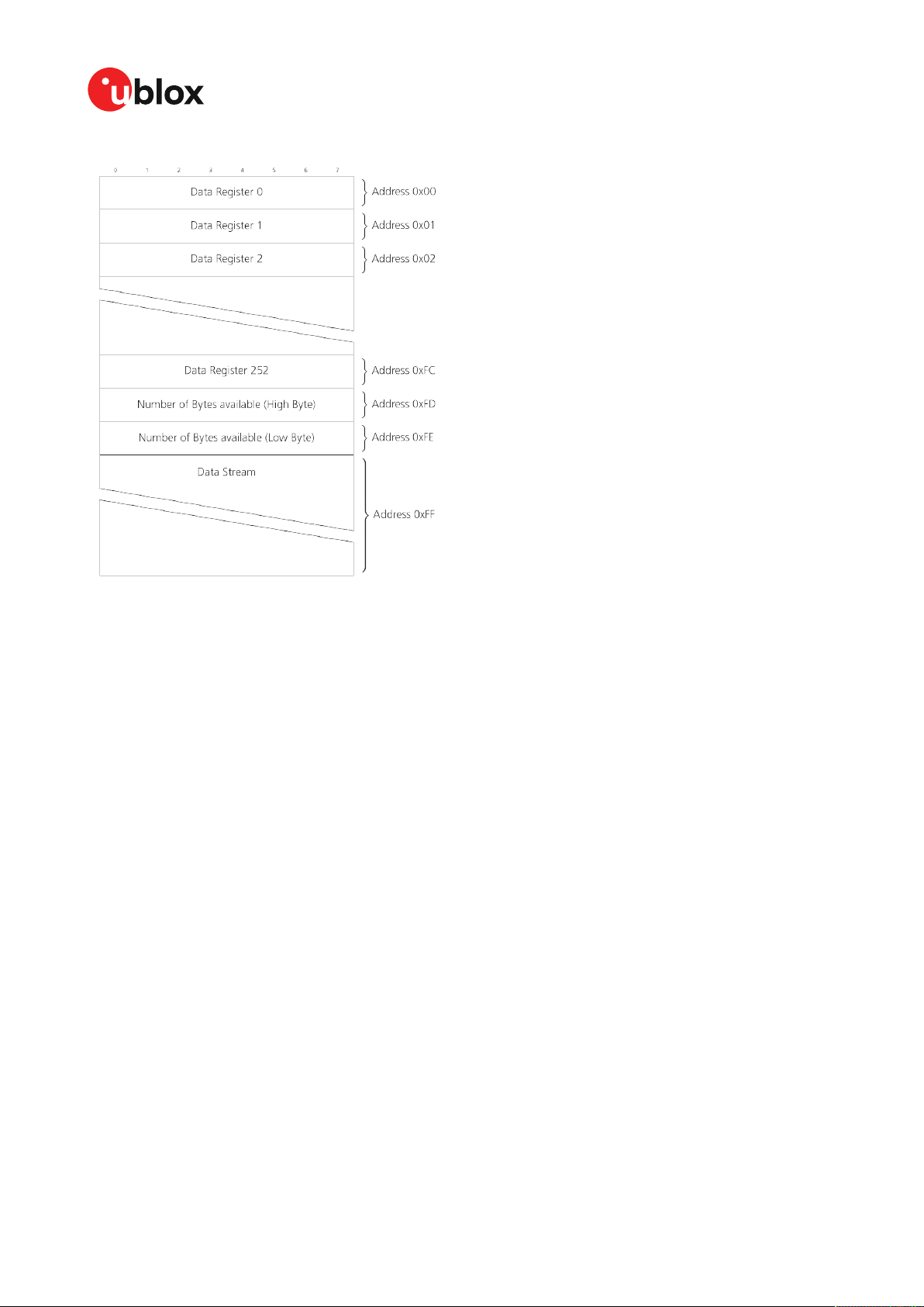
ZED-F9K-Integration manual
Figure 12: I2C register layout
3.4.2.2 Read access types
There are two I2C read transfer forms:
• The "random access" form: includes a slave register address and allows any register to be read.
• The "current address" form: omits the register address.
Figure 13 shows the format of the first one, the "random access" form of the request. Following
the start condition from the master, the 7-bit device address and the RW bit (which is a logic low
for write access) are clocked onto the bus by the master transmitter. The receiver answers with an
acknowledge (logic low) to indicate that it recognizes the address.
Next, the 8-bit address of the register to be read must be written to the bus. Following the receiver's
acknowledgment, the master again triggers a start condition and writes the device address, but this
time the RW bit is a logic high to initiate the read access. Now, the master can read 1 to N bytes
from the receiver, generating a not-acknowledge and a stop condition after the last byte being read.
UBX-20046189 - R01
C1-Public Early production information
3 Receiver functionality Page 37 of 105

ZED-F9K-Integration manual
Figure 13: I2C random read access
If the second form, "current address" is used, an address pointer in the receiver is used to determine
which register to read. This address pointer will increment after each read unless it is already
pointing at register 0xFF, the highest addressable register, in which case it remains unaltered.
The initial value of this address pointer at start-up is 0xFF, so by default all current address reads
will repeatedly read register 0xFF and receive the next byte of message data (or 0xFF if no message
data is waiting).
Figure 14: I2C current address read access
3.4.2.3 Write access
The receiver does not provide any write access except for writing UBX and NMEA messages to the
receiver, such as configuration or aiding data. Therefore, the register set mentioned in the section
Read access is not writeable.
Following the start condition from the master, the 7-bit device address and the RW bit (which is a
logic low for write access) are clocked onto the bus by the master transmitter. The receiver answers
with an acknowledge (logic low) to indicate that it is responsible for the given address.
The master can write 2 to N bytes to the receiver, generating a stop condition after the last byte
being written. The number of data bytes must be at least 2 to properly distinguish from the write
access to set the address counter in random read accesses.
UBX-20046189 - R01
C1-Public Early production information
3 Receiver functionality Page 38 of 105

ZED-F9K-Integration manual
Figure 15: I2C write access
3.4.3 SPI interface
The ZED-F9K high precision receiver has an SPI slave interface that can be selected by setting
D_SEL = 0. The SPI slave interface is shared with UART1 and I2C port, the physical pins are same.
The SPI pins available are:
• SPI_MISO (TXD)
• SPI_MOSI (RXD)
• SPI_CS_N
• SPI_CLK
See more information about communication interface selection from D_SEL section.
The SPI interface is designed to allow communication to a host CPU. The interface can be operated
in slave mode only.
3.4.3.1 Read access
As the register mode is not implemented for the SPI port, only the UBX/NMEA message stream is
provided. This stream is accessed using the back-to-back read and write access (see section Back-
to-back read and write access below). When no data is available to be written to the receiver, MOSI
should be held logic high, i.e. all bytes written to the receiver are set to 0xFF.
To prevent the receiver from being busy parsing incoming data, the parsing process is stopped after
50 subsequent bytes containing 0xFF. The parsing process is re-enabled with the first byte not equal
to 0xFF.
If the receiver has no more data to send, it sets MISO to logic high, i.e. all bytes transmitted decode
to 0xFF. An efficient parser in the host will ignore all 0xFF bytes which are not part of a message and
will resume data processing as soon as the first byte not equal to 0xFF is received.
3.4.3.2 Back-to-back read and write access
The receiver does not provide any write access except for writing UBX and NMEA messages to
the receiver, such as configuration or aiding data. For every byte written to the receiver, a byte will
simultaneously be read from the receiver. While the master writes to MOSI, at the same time it needs
to read from MISO, as any pending data will be output by the receiver with this access. The data
on MISO represents the results from a current address read, returning 0xFF when no more data is
available.
UBX-20046189 - R01
C1-Public Early production information
3 Receiver functionality Page 39 of 105

ZED-F9K-Integration manual
Figure 16: SPI back-to-back read/write access
3.4.4 USB interface
A single USB port is provided for host communication purposes.
The USB 2.0 FS (Full speed, 12 Mbit/s) interface can be used for host communication. Due to the
hardware implementation, it may not be possible to certify the USB interface.
If the receiver executes code from internal ROM (i.e. when a valid flash firmware image is not
detected), the USB behavior can differ compared to executing a firmware image from flash memory.
USB host compatibility testing is thus recommended in this scenario.
The ZED-F9K receiver supports only self-powered mode operation in which the receiver is supplied
from its own power supply. The V_USB pin is used to detect the availability of the USB port, i.e.
whether the receiver is connected to a USB host.
USB suspend mode is not supported.
USB bus-powered mode is not supported.
It is important to connect V_USB to ground and leave data lines open when the USB
interface is not used in an application.
The voltage range for V_USB is specified from 3.0 V to 3.6 V, which differs slightly from the
specification for VCC.
The boot screen is retransmitted on the USB port after enumeration. However, messages
generated between boot-up of the receiver and USB enumeration are not visible on the USB
port.
There are additional hardware requirements if USB is to be used:
• V_USB (pin 38) requires 1 uF capacitor mounted adjacent to the pin to ensure correct V_USB
voltage detection
• The V_USB (Pin 38) voltage should be sourced from an LDO enabled by the module VCC and
supplied from the USB host.
• A pull down resistor is required on the output of this V_USB LDO
• Apply USB_DM and USB_DP series resistors; typically 27 Ω
UBX-20046189 - R01
C1-Public Early production information
3 Receiver functionality Page 40 of 105

ZED-F9K-Integration manual
Figure 17: ZED-F9K example circuit for USB interface
R11 = 100 k Ω is recommended
R4, R5 = 27 Ω is recommended
3.5 Predefined PIOs
In addition to the communication ports, there are some predefined PIOs provided by ZED-F9K to
interact with the receiver. These PIOs are described in this chapter.
If hardware backup mode is used a proper isolation of the interfaces is needed.
3.5.1 D_SEL
The D_SEL pin can be used to configure the functionality of the combined UART1, I2C, and SPI pins.
It is possible to configure the pins as UART1 + I2C, or as SPI. SPI is not available unless D_SEL pin
is set to low. See Table 16 below.
Pin no.
42 SPI_MISO UART1 TXD
43 SPI_MOSI UART1 RXD
44
45 SPI_CLK I2C SCL
Table 16: D_SEL configuration
D_SEL == 0 D_SEL == 1
SPI_CS_N I2C SDA
3.5.2 RESET_N
The ZED-F9K provides the ability to reset the receiver. The RESET_N pin is an input-only pin with an
internal pull-up resistor. Driving RESET_N low for at least 100 ms will trigger a cold start.
The RESET_N pin will delete all information and trigger a cold start. It should only be used
as a recovery option.
3.5.3 SAFEBOOT_N
The ZED-F9K provides a SAFEBOOT_N pin that is used to command the receiver safe boot mode.
If this pin is low at power up, the receiver starts in safe boot mode and GNSS operation is disabled.
The safe boot mode can be used to recover from situations where the flash content has become
corrupted and needs to be restored.
In safe boot mode the receiver runs from a passive oscillator circuit with less accurate timing and
hence the receiver is unable to communicate via USB.
In this mode only UART1 , I2C or SPI communication is possible. For communication via UART1 in
safe boot mode, the host must send a training sequence (0 x 55 55 at 9600 baud) to the receiver in
order to begin communication. After this the host must wait at least 2 ms before sending any data.
UBX-20046189 - R01
C1-Public Early production information
3 Receiver functionality Page 41 of 105

ZED-F9K-Integration manual
It is recommended to have the possibility to pull the SAFEBOOT_N pin low in the application. This
can be provided using an externally connected test point or a host I/O port.
3.5.4 TIMEPULSE
The ZED-F9K high precision receiver provides a time pulse on the TIMEPULSE pin.
More information about the time pulse feature and its configuration can be found in the Time pulse
section.
3.5.5 TX_READY
This feature enables each port to define a corresponding pin, which indicates if bytes are ready to be
transmitted. A listener can wait on the TX-READY signal instead of polling the I2C or SPI interfaces.
The CFG-TXREADY message lets you configure the polarity and the number of bytes in the buffer
before the TX-READY signal goes active. By default, this feature is disabled. For USB, this feature
is configurable but might not behave as described below due to a different internal transmission
mechanism. If the number of pending bytes reaches the threshold configured for this port, the
corresponding pin will become active (configurable active-low or active-high), and stay active until
the last bytes have been transferred from software to hardware.
This is not necessarily equal to all bytes transmitted, i.e. after the pin has become inactive,
up to 16 bytes might still need to be transferred to the host.
The TX_READY pin can be selected from all PIOs which are not in use (see UBX-MON-HW3 in the
ZED-F9K Interface Description [2] for a list of the PIOs and their mapping). Each TX_READY pin is
exclusively associated to one port and cannot be shared. If PIO is invalid or already in use, only the
configuration for the specific TX_READY pin is ignored, the rest of the port configuration is applied
if valid. The acknowledge message does not indicate if the TX-READY configuration is successfully
set, it only indicates the successful configuration of the port. To validate successful configuration
of the TX_READY pin, the port configuration should be read back and the settings of TX-READY
feature verified (will be set to disabled/all zero if the settings are invalid).
The threshold when TX_READY is asserted should not be set above 2 kB as it is possible that the
internal message buffer limit is reached before this. This results in the TX_READY pin never being
set as the messages are discarded before the threshold is reached.
3.5.5.1 Extended TX timeout
If the host does not communicate over SPI or I2C for more than approximately 2 seconds, the device
assumes that the host is no longer using this interface and no more packets are scheduled for
this port. This mechanism can be changed by enabling "extended TX timeouts", in which case the
receiver delays idling the port until the allocated and undelivered bytes for this port reach 4 kB. This
feature is especially useful when using the TX-READY feature with a message output rate of less
UBX-20046189 - R01
C1-Public Early production information
3 Receiver functionality Page 42 of 105

ZED-F9K-Integration manual
than once per second, and polling data only when data is available, determined by the TX_READY
pin becoming active.
3.5.6 EXTINT
EXTINT is an external interrupt pin with fixed input voltage thresholds with respect to VCC. It can
be used for functions such as accurate external frequency aiding and on/off control. Leave open if
unused, this function is disabled by default.
3.5.7 WT and DIR inputs
ZED-F9K pin 22 (WT) is available as a wheel-tick input. Pin 23 (DIR) is available as a direction input
(forward/reverse indication).
By default the wheel tick count is derived from the rising edges of the WT input.
The WT input may be configured to use both the rising and falling edges of the wheel tick signal. To
use both edges, the wheel tick pulses shall have approximately 1:1 mark:space ratio regardless of
speed. The minimum recommended pulse width is 10 us.
For optimal performance the wheel-tick resolution should be less than 5 cm.
The wheel-tick input shall change frequency linearly with respect to the change in vehicle speed.
When the vehicle is stationary, there shall be no wheel-tick pulses at the WT input. This is especially
important at system shutdown and startup.
Performance may be affected if there are wheel-ticks on the WT pin while the vehicle is
stationary.
The DIR input shall indicate whether the vehicle is moving forwards or backwards.
By default, the DIR pin-polarity is automatically initialized once the vehicle has reached required
minimum speed of 30 km/h. The DIR pin polarity can also be configured with the CFG-SFODODIR_PINPOL key.
Incorrect operation may occur if WT input is used without a matching DIR input.
Alternatively, the vehicle WT (or speed) and DIR inputs can be provided via one of the communication
interfaces with UBX-ESF-MEAS messages. In this use case, the WT pin can be configured as
EXTINT1 to provide a time-mark for the UBX-ESF-MEAS messages. The DIR pin can be left open.
Do not exceed the maximum voltage of 3.6 V at the WT and DIR inputs.
For more information, see the ZED-F9K Interface description [2].
3.5.8 GEOFENCE_STAT interface
The ZED-F9K provides a GEOFENCE_STAT pin that indicates the current geofence status as to
whether the receiver is inside any of the active areas.
This feature can be used for example to wake up a sleeping host when a defined geofence condition
is reached. It is possible to configure up to four circular areas as geofence locations. Once configured,
the receiver continuously compares its current position with the preset geofenced areas.
For more information in this functionality, see Geofence state evaluation.
The receiver toggles the assigned pin according to the combined geofence state.
There are three possible outcomes for each geofence:
UBX-20046189 - R01
C1-Public Early production information
3 Receiver functionality Page 43 of 105

ZED-F9K-Integration manual
•
Inside - The position is inside the geofence with the configured confidence level
•
Outside - The position lies outside of the geofence with the configured confidence level
•
Unknown - There is no valid position solution or the position uncertainty does not allow for
unambiguous state evaluation
The GEOFENCE_STAT pin is always set to high level when the combine geofence state is unknown.
The low level can either represent the inside state or the outside state according to the value set in
the CFG-GEOFENCE-PINPOL configuration item. If the receiver is in software backup or in a reset,
the pin will go to high accordingly.
The CFG-GEOFENCE-PIN configuration item refers to a PIO and not a physical device pin.
The PIO number must be set so that it is mapped to the assigned geofence state device pin.
The ZED-F9K high precision receiver is assigned PIO3 that is assigned to module pin 19.
3.5.9 RTK_STAT interface
The ZED-F9K provides an RTK_STAT pin that provides an indication of the RTK positioning status.
It can be used to confirm if a valid stream of RTCM messages is being received. As valid RTCM
messages we only consider the RTCM messages that are supported and used by the receiver.
In general, the RTK_STAT level can be interpreted as follows: Alternating (blinking) pin level,
indicates that a valid stream of RTCM messages is being received and utilized but no RTK fixed
mode has been achieved. An active low pin level indicates that RTK fixed mode has been achieved.
Otherwise, the pin level is high.
The RTK_STAT pin status can be mapped to the carrSoln field of the UBX-NAV-PVT and
interpreted as follows:
• An active low pin level indicates that RTK fixed mode has been achieved
• Alternating (blinking) pin level, indicates that a valid stream of RTCM messages is being
received and utilized but no RTK fixed mode has been achieved
• An active high pin level indicates that no carrier phase solution is available
3.6 Antenna supervisor
An active antenna supervisor provides the means to check the antenna for open and short circuits
and to shut off the antenna supply if a short circuit is detected. Once enabled, the active antenna
supervisor produces status messages, reporting in NMEA and/or UBX protocol.
The antenna supervisor can be configured through the CFG-HW-ANT_* configuration items. The
current configuration of the active antenna supervisor can also be checked by polling the related
CFG-HW_ANT_* configuration items.
The current active antenna status can be determined by polling the UBX-MON-RF message. If an
antenna is connected, the initial state after power-up is “Active Antenna OK" in the UBX-MON-RF
message in the u-center "Message View".
An active antenna supervisor circuit is connected to the ANT_DET, ANT_OFF, ANT_SHORT_N
pins. For an example the open circuit detection circuit using ANT_DET, "high" = Antenna detected
(antenna consumes current); "low" = Antenna not detected (no current drawn).
The following schematic details the required circuit and the sections following it explain how to
enable and monitor each feature:
UBX-20046189 - R01
C1-Public Early production information
3 Receiver functionality Page 44 of 105

ZED-F9K-Integration manual
Figure 18: ZED-F9K antenna supervisor
The bias-t inductor must be chosen for multi-band operation; a value of 47 nH ±5% is
required for our recommended Murata part, with the current limited below its 300 mA
rating. See Antenna bias section for additional information.
Circuit shows buffer [U4]. Buffer is not strictly necessary when supplied from VCC. It is only
required when supplying antenna voltage that is not obtained from or controlled by module
VCC or VCC_RF .
Part Recommendation Comment
L1 Murata LQG15HS47NJ02/47N 300mA and >500 Ω at L band frequencies
C2 Murata GRM033R71C103KE14 CAP CER X7R 0402 10N 10% 16V
TYCO, 0.25PF, PESD0402-140 -55/+125C ESD protection diode on RF trace
Table 17: Recommended components for antenna supervisor
3.6.1 Antenna voltage control - ANT_OFF
Antenna status (as reported in UBX-MON-RF and UBX-INF-NOTICE messages) is not
reported unless the antenna voltage control has been enabled.
Enable the antenna voltage control by setting the configuration item CFG-HWANT_CFG_VOLTCTRL to true (1).
Result:
• UBX-MON-RF in u-center "Message View": Antenna status = OK. Antenna power status = ON
• ANT_OFF pin = active high to turn antenna off therefore the pin is low to enable an external
antenna.
Start-up message at power up if configuration stored:
$GNTXT,01,01,02,ANTSUPERV=AC *00
$GNTXT,01,01,02,ANTSTATUS=INIT*3B
UBX-20046189 - R01
C1-Public Early production information
3 Receiver functionality Page 45 of 105

ZED-F9K-Integration manual
$GNTXT,01,01,02,ANTSTATUS=OK*25
ANTSUPERV=AC indicates antenna control is activated
3.6.2 Antenna short detection - ANT_SHORT_N
Enable the antenna short detection by setting the configuration item CFG-HWANT_CFG_SHORTDET to true (1).
Result:
• UBX-MON-RF in u-center "Message View": Antenna status = OK. Antenna power status = ON
• ANT_OFF = active high to disable an external antenna therefore the pin is low to enable an
external antenna.
• ANT_SHORT_N = active low to detect a short therefore the pin is high (PIO pull up enabled to be
pulled low if shorted)
Start-up message at power up if configuration is stored:
$GNTXT,01,01,02,ANTSUPERV=AC SD *37
$GNTXT,01,01,02,ANTSTATUS=INIT*3B
$GNTXT,01,01,02,ANTSTATUS=OK*25
ANTSUPERV=AC SD (Antenna control and short detection activated)
Then if shorted (ANT_SHORT_N pulled low):
• UBX-MON-RF in u-center "Message View": Antenna status = SHORT. Antenna power status =
ON (Antenna power control power down when short has not been enabled = off by default).
$GNTXT,01,01,02,ANTSTATUS=SHORT*73
• ANT_OFF = active high therefore still low (still enabled as auto power down is not enabled)
After a detected antenna short, the reported antenna status will keep on being reported as
shorted. If the antenna short detection auto recovery is enabled, then the antenna status
can recover after a timeout. To recover the antenna status immediately, a power cycle is
required or configuring the antenna short detection functionality off and on.
3.6.3 Antenna short detection auto recovery
Enable the antenna short detection auto recovery by setting the configuration item CFG-HWANT_CFG_RECOVER to true (1).
Result:
• UBX-MON-RF in u-center "Message View": Antenna status = OK. Antenna power status = ON
• ANT_OFF = active high there for the PIO is low to enable an external antenna
• ANT_SHORT_N = high (PIO pull up enabled to be pulled low if shorted)
Start-up message at power up if configuration is stored:
$GNTXT,01,01,02,ANTSUPERV=AC SD PDoS SR*3E
$GNTXT,01,01,02,ANTSTATUS=INIT*3B
$GNTXT,01,01,02,ANTSTATUS=OK*25
ANTSUPERV=AC SD PDoS SR (indicates short circuit recovery added - SR)
UBX-20046189 - R01
C1-Public Early production information
3 Receiver functionality Page 46 of 105

ZED-F9K-Integration manual
Then if antenna is shorted (ANT_SHORT_N pulled low):
•
$GNTXT,01,01,02,ANTSTATUS=SHORT*73
• UBX-MON-RF in u-center "Message View": Antenna status = SHORT. Antenna power status =
OFF
• ANT_OFF = high (to disable - active high)
After a time out period receiver will re-test the short condition by enabling ANT_OFF = LOW
If a short is not present it will report antenna condition is OK:
$GNTXT,01,01,02,ANTSTATUS=OK*25
UBX-MON-RF in u-center "Message View": Antenna status = OK. Antenna power status = ON
3.6.4 Antenna open circuit detection - ANT_DETECT
Enable the antenna open circuit detection by setting the configuration item CFG-HWANT_CFG_OPENDET to true (1).
Result:
• UBX-MON-RF in u-center "Message View": Antenna status = OK. Antenna power status = ON
• ANT_OFF = active high therefore PIO is low to enable external antenna
• ANT_SHORT_N = active low therefore PIO is high (PIO pull up enabled to be pulled low if
shorted)
• ANT_DETECT = active high therefore PIO is high (PIO pull up enabled to be pulled low if antenna
not detected)
Start-up message at power up if configuration is stored:
$GNTXT,01,01,02,ANTSUPERV=AC SD OD PDoS SR*15
$GNTXT,01,01,02,ANTSTATUS=INIT*3B
$GNTXT,01,01,02,ANTSTATUS=OK*25
ANTSUPERV=AC SD OD PDoS SR (indicates open circuit detection added - OD)
Then if ANT_DETECT is pulled low to indicate no antenna:
$GNTXT,01,01,02,ANTSTATUS=OPEN*35
Then if ANT_DETECT is left floating or it is pulled high to indicate antenna connected:
$GNTXT,01,01,02,ANTSTATUS=OK*25
3.7 Multiple GNSS assistance (MGA)
The u-blox MGA services provide a proprietary implementation of an A-GNSS protocol compatible
with u-blox GNSS receivers. When a client device makes an MGA request, the service responds
with the requested data using UBX protocol messages. These messages are ready for direct
transmission to the receiver communication port without requiring any modification by the MGA
client.
The MGA services consist of AssistNow Online and Offline variants delivered by HTTP or HTTPS
protocol.
UBX-20046189 - R01
C1-Public Early production information
3 Receiver functionality Page 47 of 105

ZED-F9K-Integration manual
AssistNow Online optionally provides satellite ephemerides, health information and time aiding data
suitable for GNSS receiver systems with direct internet access.
3.7.1 Authorization
The AssistNow Online Service is only available to u-blox customers. To use the services, customers
will need to obtain an authorization token from u-blox. This token must be supplied as a parameter
whenever a request is made to either service. Contact your local technical support or go to
https://www.u-blox.com/en/solution/services/assistnow to get more information and to request an
authorization token.
3.7.2 Multiple servers
To protect customers against the impact of outages that might be caused by, for example,
maintenance activity, u-blox runs at least two instances of the AssistNow Online Service on
independent servers. u-blox recommends implementing a fallback mechanism of using another
server in case one fails. All servers provide the same information, which means that assistance data
can be requested from any of these servers.
3.7.3 Preserving information during power-off
The performance of u-blox receivers immediately after they are turned on is enhanced by providing
them with as much information as possible. The information can be fetched from the AssistNow
service, or it can be retained from the previous use of the receiver. The information from the previous
use improves the receiver's ability to calculate the current position even if the satellite signal level or
signal quality is poor. The retained information can also significantly improve time to first fix (TTFF).
There are several ways in which a u-blox receiver can retain useful data while it is powered down,
including:
• Battery-backed RAM: The receiver can be supplied with sufficient power to maintain a small
portion of internal storage, while it is otherwise turned off. This is the best mechanism,
provided that the small amount of electrical power required can be supplied continuously.
V_BCKP is the pin sustaining battery-backed RAM.
• Save-on-shutdown: The receiver can be instructed to dump its current state to the flash
memory as part of the shutdown procedure; this data is then automatically retrieved when the
receiver is restarted. For more information, see the description of the UBX-UPD-SOS messages
in the ZED-F9K Interface description [2].
3.7.4 AssistNow Online
AssistNow Online is u-blox's end-to-end Assisted GNSS (A-GNSS) solution for receivers that have
access to the internet. Data supplied by the AssistNow Online Service can be directly uploaded
to the receiver in order to substantially reduce time to first fix (TTFF), even under poor signal
conditions (typically around 2 seconds; see ZED-F9K Data sheet [1] "Aided start"). The system
works by collecting data such as ephemeris and almanac from the satellites through u-blox's "Global
Reference Network" of receivers and providing this data to customers in a convenient form that can
be forwarded directly to u-blox receivers.
The AssistNow Online Service uses an HTTP interface. Therefore, it works on all standard mobile
communication networks that support internet access, including GPRS, UMTS and Wireless LAN.
No special arrangements are needed with mobile network operators to enable AssistNow Online.
UBX-20046189 - R01
C1-Public Early production information
3 Receiver functionality Page 48 of 105

Figure 19: MGA architecture
ZED-F9K-Integration manual
The data returned by the AssistNow Online Service is a sequence of UBX-MGA messages, starting
with an estimate of the current time in the form of a UBX-MGA-INI-TIME_UTC message.
AssistNow Online supports GPS, GLONASS, BeiDou, Galileo, and QZSS.
Customers may choose to use third party sources of assistance data instead of using
the AssistNow Online Service. Customers choosing this option will need to ensure that
the data is converted from the format used by the third party source to the appropriate
MGA messages. However, it is important to ensure that the receiver has an estimate of the
current time before it processes any other assistance data. For this reason, it is strongly
recommended to send a UBX-MGA-INITIME_UTC or UBX-MGA-INI-TIME_GNSS as the first
message of any assistance.
3.7.4.1 Host software
As u-blox receivers have no means to connect directly with the internet, the AssistNow Online
system can only work if the host system that contains the receiver can connect to the internet,
download the data from the AssistNow Online Service and forward it on to the receiver. In the
simplest case that may involve fetching the data from the AssistNow Online Service (by means of a
single HTTP or HTTPS GET request), and sending the resulting data to the receiver.
Depending on the circumstances, it may be beneficial for the host software to:
• Create an appropriate UBX-MGA-INI-TIME_UTC message to deliver a better estimation of the
current time to the receiver, especially if the host system has a very good estimation of the
current time and can deliver a time pulse to one of the receiver's EXTINT pins.
• Enable and use flow control to prevent loss of data due to buffer overflow in the receiver.
u-blox provides the source code for an example library, called libMGA, that provides all of the
functionality we expect in most host software.
3.7.4.2 AssistNow Online sequence
A typical sequence of use of the AssistNow Online Service comprises the following steps:
• Power up the u-blox receiver.
• Request data from the AssistNow Online Service.
UBX-20046189 - R01
C1-Public Early production information
3 Receiver functionality Page 49 of 105

ZED-F9K-Integration manual
• Optionally send UBX-MGA-INI-TIME_UTC followed by hardware time synchronization pulse.
• Send the UBX messages obtained from the AssistNow Online Service to the receiver.
3.7.4.3 Flow control
u-blox receivers aim to process incoming messages as quickly as possible, but there will always be
a small delay in processing each message. Uploading assistance data to the receiver can involve
sending as many as one hundred individual messages to the receiver, one after the other. If the
communication link is fast, and/or the receiver is busy (trying to acquire new signals), it is possible
that the internal buffers will overflow and some messages will be lost. In order to combat this, u-blox
receivers support an optional flow control mechanism for assistance.
Flow control is activated by setting the CFG-NAVSPG-ACKAIDING configuration item. As a result
the receiver will issue an acknowledgment message (UBX-MGA-ACK) for each assistance message
it successfully receives. The host software can examine these acknowledgments to establish
whether there were any problems with the data sent to the receiver and deduce (by the lack of
acknowledgment) if any messages have been lost. It may then be necessary to resend some of the
assistance messages.
The simplest way to implement flow control would be to send one UBX-MGA message at a time,
waiting for the acknowledgment, before sending the next. However, such a strategy is likely to
introduce significant delays into the whole assistance process. The best strategy depends on the
amount of assistance data being sent and the nature of the communications link (e.g. baud rate of
serial link). u-blox recommends that when customers are developing their host software they start
by sending all assistance messages and then analyze the resulting acknowledgments to see if any
messages have been lost. Adding small delays during the transmission may be a simple but effective
way to avoid loss of data.
3.7.4.4 Service parameters
The information exchange with the AssistNow Online Service is based on the HTTP protocol. The
u-blox MGA service supports encrypted HTTPS communication. Upon reception of an HTTP GET
request, the server will respond with the required messages in binary format or with an error string
in text format. After delivery of all data, the server will terminate the connection.
The HTTP GET request from the client to the server should contain a standard HTTP query string in
the request URL. The query string consists of a set of "key=value" parameters in the following form:
key=value;key=value;key=value;
The following rules apply:
• The order of keys is important.
• Keys and values are case-sensitive.
• Keys and values must be separated by an "equal" character ("=").
• Key/value pairs must be separated by semicolons (";").
• If a value contains a list, each item in the list must be separated by a comma (",").
The following table describes the keys that are supported:
Key name Unit/range Optional Description
token String Mandatory The authorization token supplied by u-blox when a client registers to use the
gnss String Mandatory A comma-separated list of the GNSS for which data should be returned. Valid GNSS
service.
are: gps, gal, glo, bds and qzss (case-sensitive).
UBX-20046189 - R01
C1-Public Early production information
3 Receiver functionality Page 50 of 105

ZED-F9K-Integration manual
Key name Unit/range Optional Description
datatype String Mandatory A comma-separated list of the data types required by the client. Valid data types
lat Numeric
[degrees]
lon Numeric
[degrees]
alt Numeric
[meters]
pacc Numeric
[meters]
tacc Numeric
[seconds]
latency Numeric
[seconds]
filteronpos (no value
required)
filteronsv String Optional A comma-separated list of u-blox gnssId:svId pairs. The ephemeris data returned to
Table 18: AssistNow Online parameter keys
Optional Approximate user latitude in WGS 84 expressed in degrees and fractional degrees.
Optional Approximate user longitude in WGS 84 expressed in degrees and fractional
Optional Approximate user altitude above WGS 84 Ellipsoid. If this value is not provided, the
Optional Approximate accuracy of submitted position (see the Position parameters (lat, lon,
Optional The timing accuracy (see the Time parameters (tacc and latency) section below). If
Optional Typical latency between the time the server receives the request, and the time
Optional If present, the ephemeris data returned to the client will only contain data for the
are: eph, alm, aux and pos. Time data is always returned for each request. If the
value of this parameter is an empty string, only time data will be returned.
Must be in range -90 to 90. Example: lat=47.2.
degrees. Must be in range -180 to 180. Example: lon=8.55.
server assumes an altitude of 0 meters. Must be in range -1000 to 50000.
alt and pacc) section below). If this value is not provided, the server assumes an
accuracy of 300 km. Must be in range 0 to 6000000.
this value is not provided, the server assumes an accuracy of 10 seconds. Must be
in range 0 to 3600.
when the assistance data arrives at the u-blox receiver. The server can use this
value to correct the time being transmitted to the client. If this value is not
provided, the server assumes a latency of 0. Must be in range 0 to 3600.
satellites which are likely to be visible from the approximate position provided by
the lat, lon, alt and pacc parameters. If the lat and lon parameters are not provided
the service will return an error.
the client will only contain data for the listed satellites.
Thus, as an example, a valid parameter string would be:
token=XXXXXXXXXXXXXXXXXXXXXX;gnss=gps,qzss;datatype=eph,pos,aux;lat=47.28;lon=8.56;pacc=1000
3.7.4.4.1 Position parameters (lat, lon, alt and pacc)
The position parameters (lat, lon, alt and pacc) are used by the server for two purposes:
• If the filteronpos parameter is provided, the server determines the currently visible satellites
at the user position, and only sends the ephemeris data of those satellites which should be in
view at the location of the user. This reduces bandwidth requirements. In this case the "pacc"
value is taken into account, meaning that the server will return all satellites visible in the given
uncertainty region.
• If the datatype "pos" is requested, the server will return the position and accuracy in the
response data. When this data is supplied to the u-blox receiver, depending on the accuracy
of the provided data, the receiver can then choose to select a better startup strategy. For
example, if the position is accurate to 100 km or better, the u-blox receiver will choose to go
for a more optimistic startup strategy. This will result in quicker startup time. The receiver will
decide which strategy to choose, depending on the "pacc" parameter. If the submitted user
position is less accurate than what is being specified with the "pacc" parameter, the user will
experience prolonged or even failed startups.
3.7.4.4.2 Time parameters (tacc and latency)
Time data is always returned with each request. The time data refers to the time at which the
response leaves the server, corrected by an optional latency value. This time data provided by the
service is accurate to approximately 10 ms but by default the time accuracy is indicated to be +/-10
seconds in order to account for network latency and any time between the client receiving the data
and it being provided to the receiver.
UBX-20046189 - R01
C1-Public Early production information
3 Receiver functionality Page 51 of 105

ZED-F9K-Integration manual
If both the network latency and the client latency can safely be assumed to be very low (or are
known), the client can choose to set the accuracy of the time message (tacc) to a much smaller value
(e.g. 0.5 s). This will result in a faster TTFF. The latency can also be adjusted as needed. However,
these fields should be used with caution: if the time accuracy is not correct when the time data
reaches the receiver, the receiver may experience prolonged or even failed startups.
For optimal results, the client should establish an accurate sense of time itself (e.g. by calibrating
its system clock using a local NTP service) and then modify the time data received from the service
as appropriate.
3.8 Save-on-shutdown feature
The save-on-shutdown feature (SOS) enables the u-blox receiver to store the contents of the
battery-backed RAM to an external flash memory and restore it upon startup. This allows the ublox receiver to preserve some of the features available only with a battery backup (preserving
configuration, IMU calibration, and satellite orbit knowledge) without having a battery backup
supply present. It does not, however, preserve any kind of time knowledge. Save-on-shutdown
must be commanded by the host. The restoring of data on startup is automatically done if the
corresponding data is present in the flash. Data expiration is not checked.
The following outlines the suggested shutdown procedure when using the save-on-shutdown
feature:
• With the UBX-CFG-RST message, the host commands the u-blox receiver to stop, specifying
reset mode 0x08 ("Controlled GNSS stop") and a BBR mask of 0 ("Hotstart").
• The host commands the saving of the contents of BBR to the flash memory using the UBX-
UPD-SOS-BACKUP message.
• For a valid request the u-blox receiver reports on the success of the backup operation with a
UBX-UPD-SOS-ACK message.
• The host powers off the u-blox receiver.
The startup procedure is as follows:
• The host powers on the u-blox receiver.
• The u-blox receiver detects the previously stored data in the flash. It restores the corresponding
memory and reports the success of the operation with a UBX-UPD-SOS-RESTORED message
on the port on which it had received the save command message (if the output protocol filter on
that port allows it). It does not report anything if no stored data has been detected.
• Additionally the u-blox receiver outputs a UBX-INF-NOTICE and/or a NMEA-TXT message
with the contents RESTORED in the boot screen (depends on the configuration of the port and
information messages) upon success.
• Optionally the host can deliver coarse time assistance using UBX-MGA-INI-TIME_UTC for
better startup performance.
Once the u-blox receiver has started up it is recommended to delete the stored data using a UBXUPD-SOS-CLEAR message. The u-blox receiver responds with a UBX-ACK-ACK / UBX-ACK-NAK
message.
UBX-20046189 - R01
C1-Public Early production information
3 Receiver functionality Page 52 of 105

ZED-F9K-Integration manual
3.9 Clocks and time
This section introduces and explains the concepts of receiver clocks and time bases.
3.9.1 Receiver local time
The receiver is dependent on a local oscillator for both the operation of its radio parts and also for
timing within its signal processing. No matter what nominal frequency the local oscillator has, u-blox
receivers subdivide the oscillator signal to provide a 1-kHz reference clock signal, which is used to
drive many of the receiver's processes. In particular, the measurement of satellite signals is arranged
to be synchronized with the "ticking" of this 1-kHz clock signal.
When the receiver first starts, it has no information about how these clock ticks relate to other time
systems; it can only count time in 1 millisecond steps. However, as the receiver derives information
from the satellites it is tracking or from aiding messages, it estimates the time that each 1-kHz
clock tick takes in the time-base of the chosen GNSS system. This estimate of GNSS time based on
the local 1-kHz clock is called receiver local time.
As receiver local time is a mapping of the local 1-kHz reference onto a GNSS time-base, it
may experience occasional discontinuities, especially when the receiver first starts up and the
information it has about the time-base is changing. Indeed, after a cold start, the receiver local
time will initially indicate the length of time that the receiver has been running. However, when the
receiver obtains some credible timing information from a satellite or an aiding message, it will jump
to an estimate of GNSS time.
3.9.2 Navigation epochs
Each navigation solution is triggered by the tick of the 1-kHz clock nearest to the desired navigation
solution time. This tick is referred to as a navigation epoch. If the navigation solution attempt is
successful, one of the results is an accurate measurement of time in the time-base of the chosen
GNSS system, called GNSS system time. The difference between the calculated GNSS system time
and receiver local time is called the clock bias (and the clock drift is the rate at which this bias is
changing).
In practice the receiver's local oscillator will not be as stable as the atomic clocks to which GNSS
systems are referenced and consequently clock bias will tend to accumulate. However, when
selecting the next navigation epoch, the receiver will always try to use the 1-kHz clock tick which it
estimates to be closest to the desired fix period as measured in GNSS system time. Consequently
the number of 1-kHz clock ticks between fixes will occasionally vary. This means that when
producing one fix per second, there will normally be 1000 clock ticks between fixes, but sometimes,
to correct drift away from GNSS system time, there will be 999 or 1001.
The GNSS system time calculated in the navigation solution is always converted to a time in both
the GPS and UTC time-bases for output.
Clearly when the receiver has chosen to use the GPS time-base for its GNSS system time, conversion
to GPS time requires no work at all, but conversion to UTC requires knowledge of the number of
leap seconds since GPS time started (and other minor correction terms). The relevant GPS-to-UTC
conversion parameters are transmitted periodically (every 12.5 minutes) by GPS satellites, but can
also be supplied to the receiver via the UBX-MGA-GPS-UTC aiding message. By contrast when the
receiver has chosen to use the GLONASS time-base as its GNSS system time, conversion to GPS
time is more difficult as it requires knowledge of the difference between the two time-bases, but as
GLONASS time is closely linked to UTC, conversion to UTC is easier.
UBX-20046189 - R01
C1-Public Early production information
3 Receiver functionality Page 53 of 105

ZED-F9K-Integration manual
When insufficient information is available for the receiver to perform any of these time-base
conversions precisely, pre-defined default offsets are used. Consequently plausible times are nearly
always generated, but they may be wrong by a few seconds (especially shortly after receiver start).
Depending on the configuration of the receiver, such "invalid" times may well be output, but with
flags indicating their state (e.g. the "valid" flags in UBX-NAV-PVT).
u-blox receivers employ multiple GNSS system times and/or receiver local times (in order
to support multiple GNSS systems concurrently), so users should not use UBX messages
reporting GNSS system time or receiver local time. It is recommended to use messages that
report UTC time and other messages are retained only for backwards compatibility reasons.
3.9.3 iTOW timestamps
All the main UBX-NAV messages (and some other messages) contain an iTOW field which indicates
the GPS time at which the navigation epoch occurred. Messages with the same iTOW value can be
assumed to have come from the same navigation solution.
With Priority navigation mode enabled, iTOW can be used as an epoch collector only for
messages of the same group (e.g. priority navigation messages with the same iTOW value
can be assumed to have come from the same navigation solution).
Note that iTOW values may not be valid (i.e. they may have been generated with insufficient
conversion data) and therefore it is not recommended to use the iTOW field for any other purpose.
The original designers of GPS chose to express time/date as an integer week number
(starting with the first full week in January 1980) and a time of week (often abbreviated
to TOW) expressed in seconds. Manipulating time/date in this form is far easier for digital
systems than the more conventional year/month/day, hour/minute/second representation.
Consequently, most GNSS receivers use this representation internally, only converting to a
more conventional form at external interfaces. The iTOW field is the most obvious externally
visible consequence of this internal representation.
If reliable absolute time information is required, users are recommended to use the UBX-NAV-PVT
navigation solution message which also contains additional fields that indicate the validity (and
accuracy in UBX-NAV-PVT) of the calculated times (see also the GNSS times section below for
further messages containing time information).
3.9.4 GNSS times
Each GNSS has its own time reference for which detailed and reliable information is provided in the
messages listed in the table below.
Time reference Message
GPS time UBX-NAV-TIMEGPS
BeiDou time UBX-NAV-TIMEBDS
GLONASS time UBX-NAV-TIMEGLO
Galileo time UBX-NAV-TIMEGAL
UTC time UBX-NAV-TIMEUTC
Table 19: GNSS times
3.9.5 Time validity
Information about the validity of the time solution is given in the following form:
•
Time validity: Information about time validity is provided in the valid flags (e.g. validDate
and validTime flags in the UBX-NAV-PVT message). If these flags are set, the time is known
UBX-20046189 - R01
C1-Public Early production information
3 Receiver functionality Page 54 of 105

ZED-F9K-Integration manual
and considered valid for use. These flags are shown in table GNSS times in section GNSS times
above as well as in the UBX-NAV-PVT message.
• Time validity confirmation: Information about confirmed validity is provided in the
confirmedDate and confirmedTime flags in the UBX-NAV-PVT message. If these flags are
set, the time validity can be confirmed by using an additional independent source, meaning
that the probability of the time to be correct is very high. Note that information about time
validity confirmation is only available if the confirmedAvai bit in the UBX-NAV-PVT message
is set.
validDate means that the receiver has knowledge of the current date. However, it must
be noted that this date might be wrong for various reasons. Only when the confirmedDate
flag is set, the probability of the incorrect date information drops significantly.
validTime means that the receiver has knowledge of the current time. However, it must
be noted that this time might be wrong for various reasons. Only when the confirmedTime
flag is set, the probability of incorrect time information drops significantly.
fullyResolved means that the UTC time is known without full seconds ambiguity. When
deriving UTC time from GNSS time the number of leap seconds must be known, with the
exception of GLONASS. It might take several minutes to obtain such information from the
GNSS payload. When the one second ambiguity has not been resolved, the time accuracy is
usually in the range of ~20s.
3.9.6 UTC representation
UTC time is used in many NMEA and UBX messages. In NMEA messages it is always reported
rounded to the nearest hundredth of a second. Consequently, it is normally reported with
two decimal places (e.g. 124923.52). Although compatibility mode (selected using CFG-NMEACOMPAT) requires three decimal places, rounding to the nearest hundredth of a second remains, so
the extra digit is always 0.
UTC time is also reported within some UBX messages, such as UBX-NAV-TIMEUTC and UBX-NAVPVT. In these messages date and time are separated into seven distinct integer fields. Six of
these (year, month, day, hour, min and sec) have fairly obvious meanings and are all guaranteed to
match the corresponding values in NMEA messages generated by the same navigation epoch. This
facilitates simple synchronization between associated UBX and NMEA messages.
The seventh field is called nano and it contains the number of nanoseconds by which the rest of
the time and date fields need to be corrected to get the precise time. So, for example, the UTC time
12:49:23.521 would be reported as: hour: 12, min: 49, sec: 23, nano: 521000000.
It is however important to note that the first six fields are the result of rounding to the nearest
hundredth of a second. Consequently the nano value can range from -5000000 (i.e. -5 ms) to
+994999999 (i.e. nearly 995 ms).
When the nano field is negative, the number of seconds (and maybe minutes, hours, days, months
or even years) will have been rounded up. Therefore, some or all of them must be adjusted in order
to get the correct time and date. Thus in an extreme example, the UTC time 23:59:59.9993 on 31st
December 2011 would be reported as: year: 2012, month: 1, day: 1, hour: 0, min: 0, sec: 0, nano:
-700000.
Of course, if a resolution of one hundredth of a second is adequate, negative nano values can simply
be rounded up to 0 and effectively ignored.
Which master clock the UTC time is referenced to is output in the message UBX-NAV-TIMEUTC.
UBX-20046189 - R01
C1-Public Early production information
3 Receiver functionality Page 55 of 105

ZED-F9K-Integration manual
The preferred variant of UTC time can be specified using CFG-NAVSPG-UTCSTANDARD
configuration item.
3.9.7 Leap seconds
Occasionally it is decided (by one of the international time keeping bodies) that, due to the slightly
uneven spin rate of the Earth, UTC has moved sufficiently out of alignment with mean solar time (i.e.
the Sun no longer appears directly overhead at 0 longitude at midday). A "leap second" is therefore
announced to bring UTC back into close alignment. This normally involves adding an extra second
to the last minute of the year, but it can also happen on 30th June. When this happens UTC clocks
are expected to go from 23:59:59 to 23:59:60 and only then on to 00:00:00.
It is also theoretically possible to have a negative leap second, in which case there will only be 59
seconds in a minute and 23:59:58 will be followed by 00:00:00.
u-blox receivers are designed to handle leap seconds in their UTC output and consequently users
processing UTC times from either NMEA or UBX messages should be prepared to handle minutes
that are either 59 or 61 seconds long.
Leap second information can be polled from the u-blox receiver with the message UBX-NAV-TIMELS.
3.9.8 Real-time clock
u-blox receivers contain circuitry to support a real-time clock, which (if correctly fitted and powered)
keeps time while the receiver is otherwise powered off. When the receiver powers up, it attempts to
use the real-time clock to initialize receiver local time and in most cases this leads to appreciably
faster first fixes.
3.9.9 Date
All GNSS frequently transmit information about the current time within their data message. In most
cases, this is a time of week (often abbreviated to TOW), which indicates the elapsed number of
seconds since the start of the week (midnight Saturday/Sunday). In order to map this to a full date,
it is necessary to know the week and so the GNSS also transmit a week number, typically every 30
seconds. Unfortunately the GPS L1C/A data message was designed in a way that only allows the
bottom 10 bits of the week number to be transmitted. This is not sufficient to yield a completely
unambiguous date as every 1024 weeks (a bit less than 20 years), the transmitted week number
value "rolls over" back to zero. Consequently, GPS L1 receivers cannot tell the difference between,
for example, 1980, 1999 or 2019 etc.
Fortunately, although BeiDou and Galileo have similar representations of time, they transmit
sufficient bits for the week number to be unambiguous for the foreseeable future (the first
ambiguity will be in 2078 for Galileo and not until 2163 for BeiDou). GLONASS has a different
structure, based on a time of day, but again transmits sufficient information to avoid any ambiguity
during the expected lifetime of the system (the first ambiguous date will be in 2124). Therefore, ublox 9 receivers using Protocol Version 24 and above regard the date information transmitted by
GLONASS, BeiDou and Galileo to be unambiguous and, where necessary, use this to resolve any
ambiguity in the GPS date.
Customers attaching u-blox receivers to simulators should be aware that GPS time is
referenced to 6th January 1980, GLONASS to 1st January 1996, Galileo to 22nd August
1999 and BeiDou to 1st January 2006; the receiver cannot be expected to work reliably with
signals simulated before these dates.
UBX-20046189 - R01
C1-Public Early production information
3 Receiver functionality Page 56 of 105

ZED-F9K-Integration manual
3.9.9.1 GPS-only date resolution
In circumstances where only GPS L1C/A signals are available and for receivers with earlier firmware
versions, the receiver establishes the date by assuming that all week numbers must be at least
as large as a reference rollover week number. This reference rollover week number is hard-coded
at compile time and is normally set a few weeks before the software is completed, but it can be
overridden by CFG-NAVSPG-WKNROLLOVER configuration item to any value the user wishes.
The following example illustrates how this works: Assume that the reference rollover week number
set in the firmware at compile time is 1524 (which corresponds to a week in calendar year 2009,
but would be transmitted by the satellites as 500). In this case, if the receiver sees transmissions
containing week numbers in the range of 500 ... 1023, these will be interpreted as week numbers
1524 ... 2047 (calendar year 2009 ... 2019), whereas transmissions with week numbers from 0 to
499 are interpreted as week numbers 2048 ... 2547 (calendar year 2019 ... 2028).
It is important to set the reference rollover week number appropriately when supplying ublox receivers with simulated signals, especially when the scenarios are in the past.
3.9.10 Time pulse
3.9.10.1 Introduction
u-blox receivers include a time pulse function providing clock pulses with configurable duration and
frequency. The time pulse function can be configured using the CFG-TP-* configuration group. The
UBX-TIM-TP message provides time information for the next pulse and the time source.
Figure 20: Time pulse
3.9.10.2 Recommendations
• The time pulse can be aligned to a wide variety of GNSS times or to variants of UTC derived
from them (see the chapter on time bases). However, it is strongly recommended that the
choice of time base is aligned with the available GNSS signals (so to produce GPS time or
UTC(USNO), ensure GPS signals are available, and for GLONASS time or UTC(SU) ensure
the presence GLONASS signals). This will involve coordinating the setting of CFG-SIGNAL-*
configuration group with the choice of time pulse time base.
• When using time pulse for precision timing applications it is recommended to calibrate the
antenna cable delay against a reference timing source.
•
To get the best timing accuracy with the antenna, a fixed and accurate position is needed.
UBX-20046189 - R01
C1-Public Early production information
3 Receiver functionality Page 57 of 105
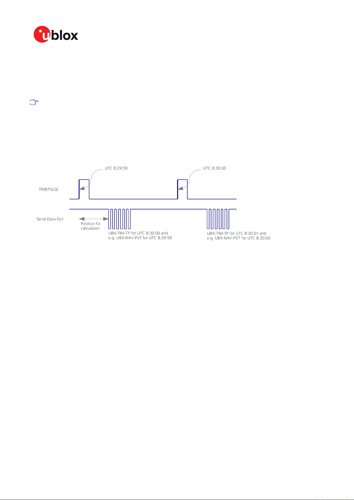
ZED-F9K-Integration manual
• If relative time accuracy between multiple receivers is required, do not mix receivers of different
product families. If this is required, the receivers must be calibrated accordingly, by setting
cable delay and user delay.
• The recommended configuration when using the UBX-TIM-TP message is to set both the
measurement rate (CFG-RATE-MEAS) and the time pulse frequency (CFG-TP-*) to 1 Hz.
Since the rate of UBX-TIM-TP is bound to 1 Hz, more than one UBX-TIM-TP message can
appear between two pulses if the time pulse frequency is set larger than 1 Hz. In this case
all UBX-TIM-TP messages in between time pulses T1 and T2 belong to T2 and the last UBXTIM-TP before T2 reports the most accurate quantization error. In general, if the time pulse
rate is not configured to 1 Hz, there will not be a single UBX-TIM-TP message for each time
pulse.
The sequential order of the signal present at the TIMEPULSE pin and the respective output message
for the simple case of 1 pulse per second (1PPS) is shown in the following figure.
Figure 21: Time pulse and TIM-TP
3.9.10.3 GNSS time bases
GNSS receivers must handle a variety of different time bases as each GNSS has its own reference
system time. What is more, although each GNSS provides a model for converting their system time
into UTC, they all support a slightly different variant of UTC. So, for example, GPS supports a variant
of UTC as defined by the US National Observatory, while BeiDou uses UTC from the National Time
Service Center, China (NTSC). While the different UTC variants are normally closely aligned, they
can differ by as much as a few hundreds of nanoseconds.
Although u-blox receivers can combine a variety of different GNSS times internally, the user must
choose a single type of GNSS time and, separately, a single type of UTC for input (on EXTINTs) and
output (via the time pulse) and the parameters reported in corresponding messages.
The CFG-TP-* configuration group allows the user to choose between any of the supported GNSS
(GPS, GLONASS, BeiDou, etc) times and UTC. Also, the CFG-NAVSPG-* configuration group allows
the user to select which variant of UTC the receiver should use. This includes an "automatic"
option which causes the receiver to select an appropriate UTC version itself, based on the GNSS
configuration, using, in order of preference, USNO if GPS is enabled, SU if GLONASS is enabled, NTSC
if BeiDou is enabled and, finally, European if Galileo is enabled.
The receiver will assume that the input time pulse uses the same GNSS time base as specified for
the output using CFG-TP-*. So if the user selects GLONASS time for time pulse output, any time
pulse input must also be aligned to GLONASS time (or to the separately chosen variant of UTC).
Where UTC is selected for time pulse output, any GNSS time pulse input will be assumed to be
aligned to GPS time.
UBX-20046189 - R01
C1-Public Early production information
3 Receiver functionality Page 58 of 105

ZED-F9K-Integration manual
u-blox receivers allow users to independently choose GNSS signals used in the receiver
(using CFG-SIGNAL-*) and the input/output time base (using CFG-TP-*). For example it
is possible to instruct the receiver to use GPS and GLONASS satellite signals to generate
BeiDou time. This practice will compromise timepulse accuracy if the receiver cannot
measure the timing difference between the constellations directly and is therefore not
recommended.
The information that allows GNSS times to be converted to the associated UTC times is
only transmitted by the GNSS at relatively infrequent periods. For example GPS transmits
UTC(USNO) information only once every 12.5 minutes. Therefore, if a time pulse is
configured to use a variant of UTC time, after a cold start, substantial delays before the
receiver has sufficient information to start outputting the time pulse can be expected.
3.9.10.4 Time pulse configuration
u-blox ZED-F9K receivers provide a time pulse (TIMEPULSE) signal with a configurable pulse period,
pulse length and polarity (rising or falling edge).
It is possible to define different signal behavior (i.e. output frequency and pulse length) depending
on whether or not the receiver is locked to a reliable time source. Time pulse signal can be configured
using the configuration group CFG-TP-*.
3.9.10.5 Configuring time pulse with CFG-TP-*
The configuration group CFG-TP-* can be used to change the time pulse settings, and includes the
following parameters defining the pulse:
• timepulse enable - If this item is set, the time pulse is active.
• frequency/period type - Determines whether the time pulse is interpreted as frequency or
period.
• length/ratio type - Determines whether the time pulse length is interpreted as length [us] or
pulse ratio [%].
• antenna cable delay - Signal delay due to the cable between the antenna and the receiver.
• pulse frequency/period - Frequency or pulse time period when locked mode is not configured or
active.
• pulse frequency/period lock - Frequency or pulse time period, as soon as the receiver has
calculated a valid time from a received signal. Only used if the corresponding item is set to use
another setting in locked mode.
• pulse length/ratio - Length or duty cycle of the generated pulse, either specifies a time or ratio
for the pulse to be on/off.
• pulse length/ratio lock - Length or duty cycle of the generated pulse, as soon as the receiver
has calculated a valid time from a received signal. Only used if the corresponding item is set to
use another setting in locked mode.
• user delay - The cable delay from the receiver to the user device plus signal delay of any user
application.
• lock to GNSS freq - If this item is set, uses the frequency gained from the GNSS signal
information rather than the local oscillator's frequency.
• locked other setting - If this item is set, the alternative setting will be used as soon as the
receiver can calculate a valid time. This mode can be used, for example, to disable time pulse if
the time is not locked, or to indicate a lock with different duty cycles.
• align to TOW - If this item is set, pulses are aligned to the top of a second.
• polarity - If set, the first edge of the pulse is a rising edge (pulse polarity: rising).
• grid UTC/GNSS - Selection between UTC (0), GPS (1), GLONASS (2) and BeiDou (3) timegrid.
Also affects the time output by UBX-TIM-TP message.
The maximum pulse length cannot exceed the pulse period.
UBX-20046189 - R01
C1-Public Early production information
3 Receiver functionality Page 59 of 105
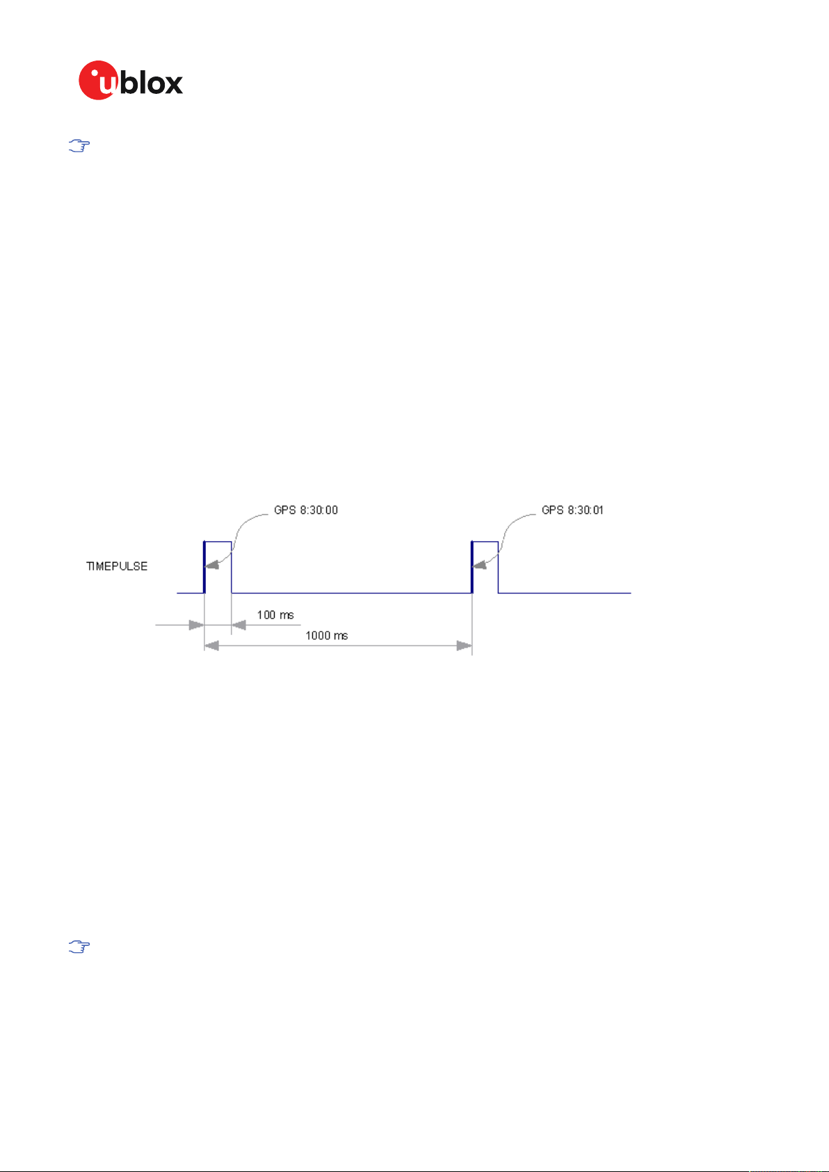
ZED-F9K-Integration manual
Time pulse settings shall be chosen in such a way that neither the high nor the low period of
the output is less than 50 ns (except when disabling it completely), otherwise pulses can be
lost.
3.9.10.5.1 Example
The example below shows the 1PPS TIMEPULSE signal generated on the time pulse output
according to the specific parameters of the CFG-TP-* configuration group:
• CFG-TP-TP1_ENA = 1
• CFG-TP-PERIOD_TP1 = 1 000 000 µs
• CFG-TP-LEN_TP1 = 100 000 µs
• CFG-TP-TIMEGRID_TP1 = 1 (GPS)
• CFG-TP-PULSE_LENGTH_DEF = 0 (Period)
• CFG-TP-ALIGN_TO_TOW_TP1 = 1
• CFG-TP-USE_LOCKED_TP1 = 1
• CFG-TP-POL_TP1 = 1
• CFG-TP-PERIOD_LOCK_TP1 = 100 000 µs
• CFG-TP-LEN_LOCK_TP1 = 100 000 µs
The 1 Hz output is maintained whether or not the receiver is locked to GPS time. The alignment to
TOW can only be maintained when GPS time is locked.
Figure 22: Time pulse signal with the example parameters
3.9.11 Timemark
The receiver can be used to provide an accurate measurement of the time at which a pulse was
detected on the external interrupt pin. The reference time can be chosen by setting the time source
parameter to UTC, GPS, GLONASS, BeiDou, Galileo or local time in the CFG-TP-* configuration group.
The UTC standard can be set in the CFG-NAVSPG-* configuration group. The delay figures defined
with CFG-TP-* are also applied to the results output in the UBX-TIM-TM2 message.
A UBX-TIM-TM2 message is output at the next epoch if
• The UBX-TIM-TM2 message is enabled, and
• A rising or falling edge was triggered since last epoch on one of the EXTINT channels.
The UBX-TIM-TM2 messages includes the time of the last timemark, new rising/falling edge
indicator, time source, validity, number of marks and an accuracy estimate.
Only the last rising and falling edge detected between two epochs is reported since the
output rate of the UBX-TIM-TM2 message corresponds to the measurement rate configured
with CFG-RATE-MEAS (see Figure 23 below).
UBX-20046189 - R01
C1-Public Early production information
3 Receiver functionality Page 60 of 105

ZED-F9K-Integration manual
Figure 23: Timemark
3.10 Security
The security concept of ZED-F9K covers the air interface between the receiver and the GNSS
satellites and the integrity of the receiver itself.
There are functions to monitor/detect certain security threads and report it to the host system.
Other functions try to mitigate the thread and allow the receiver to operate normally.
The table below gives an overview about possible threads and which functionality is available to
detect and/or mitigate it.
Threat u-blox solution
Over air signal integrity Spoofing detection/mitigation
Jamming detection/mitigation
GNSS receiver integrity Secure boot
Secure firmware update
Receiver configuration lockdown
Table 20: u-blox security options
3.10.1 Spoofing detection / monitoring
Spoofing is the process whereby someone tries to forge a GNSS signal with the intention of fooling
the receiver into calculating a different user position than the true one.
UBX-20046189 - R01
C1-Public Early production information
3 Receiver functionality Page 61 of 105

ZED-F9K-Integration manual
The spoofing detection feature monitors the GNSS signals for suspicious patterns indicating that
the receiver is being spoofed. A flag in UBX-NAV-STATUS message (flags2 - spoofDetState) alerts
the user to potential spoofing.
The spoofing detection feature monitors suspicious changes in the GNSS signal indicating external
manipulation. Therefore the detection is only successful when the signal is genuine first and when
the transition to the spoofed signal is being observed directly. When a receiver is started up
to a spoofed signal the detection algorithms will be unable to recognize the spoofing. Also, the
algorithms rely on availability of signals from multiple GNSS constellations; the detection does not
work in single-GNSS mode.
3.10.2 Jamming/interference indicator
The field jamInd of the UBX-MON-RF message can be used as an indicator for continuous
wave (narrow-band) jammers/interference only. The interpretation of the value depends on the
application. It is necessary to run the receiver in an unjammed environment to determine an
appropriate threshold for the unjammed case. If the value rises significantly above this threshold,
this indicates that a continuous wave jammer is present.
This monitoring function is always enabled.
The indicator reports any currently detected narrow-band interference over all currently configured
signal bands.
3.10.2.1 Jamming/interference monitor (ITFM) / broadband interference monitoring
The field flags of the UBX-MON-RF message can be used as an indicator for both broadband and
continuous wave (CW) jammers/interference. It is independent of the (CW only) jamming indicator
described in Jamming/interference indicator above.
This monitor reports whether jamming has been detected or suspected by the receiver. The receiver
monitors the background noise and looks for significant changes. Normally, with no interference
detected, it will report "OK". If the receiver detects that the noise has risen above a preset threshold,
the receiver reports "Warning". If in addition, there is no current valid fix, the receiver reports
"Critical".
The monitor has four states as shown in the following table:
Value Reported state Description
0 Unknown Jamming/interference monitor not enabled,
1 OK no interference detected
2 Warning position OK but interference is visible (above the
3 Critical no reliable position fix and interference is visible (above
Table 21: Jamming/interference monitor reported states
uninitialized or antenna disconnected
thresholds)
the thresholds); interference is probable reason why
there is no fix
The monitor is disabled by default. The monitor is enabled by setting the CFG-ITFM-ENABLE
configuration item. In this message it is also possible to specify the thresholds at which broadband
and CW jamming are reported. These thresholds should be interpreted as the dB level above
"normal". It is also possible to specify whether the receiver expects an active or a passive antenna.
UBX-20046189 - R01
C1-Public Early production information
3 Receiver functionality Page 62 of 105

ZED-F9K-Integration manual
The monitoring algorithm relies on comparing the currently measured spectrum with a
reference from when a good fix was obtained. Thus the monitor will only function when the
receiver has had at least one (good) first fix, and will report "Unknown" before this time.
The monitor is reporting any currently detected interference over all currently configured signal
bands.
3.10.3 GNSS receiver integrity
3.10.3.1 Secure boot
The ZED-F9K boots only with firmware images that are signed by u-blox. This prevents the execution
of non-genuine firmware images run on the receiver.
3.10.3.2 Secure firmware update
The firmware image itself is encrypted and signed by u-blox. The ZED-F9K verifies the signature at
each start.
3.10.3.3 Receiver configuration lockdown
The receiver configuration lockdown feature ensures that no configuration changes are possible
once the feature is enabled. The configuration lockdown is enabled by setting the configuration item
CFG-SEC-CFG_LOCK to "true".
The configuration lockdown can be applied to different configuration layers including the RAM,
BBR, and flash memory. At startup, the receiver constructs the configuration database from
different configuration layers and maintains it in the run-time RAM memory. When the configuration
lockdown is set in the run-time RAM, the receiver configuration cannot be changed on any
configuration layer.
For more information on the configuration layers including the order of priority they are
applied in, see the ZED-F9K Interface description [2].
The configuration lockdown set on a configuration layer in volatile memory (RAM, BBR) is removed
when the memory is cleared. However, the configuration lockdown set in non-volatile memory (flash
memory) is permanent apart from one exception: during firmware upload to flash memory, the flash
is erased during the process causing the configuration lockdown to be cleared. Refer to Firmware
upload for more information on firmware update.
To test the lockdown functionality, set it on the RAM configuration layer. After a power cycle, the
information on RAM layer is cleared and the lockdown is no longer set.
It is recommended to apply the configuration lockdown on the same layer the configuration
is stored.
3.11 u-blox protocol feature descriptions
3.11.1 Broadcast navigation data
This section describes the data reported via UBX-RXM-SFRBX.
UBX-RXM-SFRBX reports the broadcast navigation data message the receiver has collected from
each tracked signal. When enabled, a separate message is generated each time the receiver decodes
a complete subframe of data from a tracked signal. The data bits are reported as received, including
preambles and error checking bits as appropriate. However, because there is considerable variation
in the data structure of the different GNSS signals, the form of the reported data also varies. This
UBX-20046189 - R01
C1-Public Early production information
3 Receiver functionality Page 63 of 105

ZED-F9K-Integration manual
document uses the term "subframe", but other GNSS data structures might use different terms, for
example, GLONASS uses "strings" and Galileo uses "pages".
3.11.1.1 Parsing navigation data subframes
Each UBX-RXM-SFRBX message contains a subframe of data bits appropriate for the relevant
GNSS, delivered in a number of 32-bit words, as indicated by numWords field.
Due to the variation in data structure between different GNSS, the most important step in parsing
a UBX-RXMSFRBX message is to identify the form of the data. This should be done by reading the
gnssId field, which indicates which GNSS the data was decoded from. In almost all cases, this is
sufficient to indicate the structure. Because of this, the following sections are organized by GNSS.
However, in some cases the identity of the GNSS is not sufficient, and this is described, where
appropriate, in the following sections.
In most cases, the data does not map perfectly into a number of 32-bit words and, consequently,
some of the words reported in UBX-RXM-SFRBX messages contain fields marked as "Pad". These
fields should be ignored and no assumption should be made about their contents.
UBX-RXM-SFRBX messages are only generated when complete subframes are detected by the
receiver and all appropriate parity checks have passed.
Where the parity checking algorithm requires data to be inverted before it is decoded (e.g. GPS
L1C/A), the receiver carries this out before the message output. Therefore, users can process data
directly and do not need to worry about repeating any parity processing.
The meaning of the content of each subframe depends on the sending GNSS and is described in the
relevant interface control documents (ICD).
3.11.1.2 GPS
The data message structure in the GPS L1C/A (LNAV) and L2C/L5 (CNAV) signals is different and
thus the UBX-RXM-SFRBX message structure differs as well. For the GPS L1C/A and L2C/L5 signals
it is as follows:
3.11.1.2.1 GPS L1C/A
For GPS L1C/A signals, there is a fairly straightforward mapping between the reported subframe
and the structure of subframe and words described in the GPS ICD. Each subframe comprises ten
data words, which are reported in the same order they are received.
Each word is arranged as follows:
Figure 24: GPS L1C/A subframe word
3.11.1.2.2 GPS L2C
For GPS L2C signals each reported subframe contains the CNAV message as described in the GPS
ICD. The ten words are arranged as follows:
UBX-20046189 - R01
C1-Public Early production information
3 Receiver functionality Page 64 of 105

ZED-F9K-Integration manual
Figure 25: GPS L2C subframe words
3.11.1.3 GLONASS
For GLONASS L1OF and L2OF signals, the UBX-RXM-SFRBX message contains a string content
within the frame structure as described in the GLONASS ICD. This string comprises 85 data bits
which are reported over three 32-bit words in the message. Data bits 1 to 8 are always a hamming
code, whilst bits 81 to 84 are a string number and bit 85 is the idle chip, which should always have a
value of zero. The meaning of other bits varies with string and frame number.
The fourth and final 32-bit word in the UBX-RXM-SFRBX message contains frame and superframe
numbers (where available). These values are not actually transmitted by the satellites, but are
deduced by the receiver and are included to aid decoding of the transmitted data. However, the
receiver does not always know these values, in which case a value of zero is reported.
The four words are arranged as follows:
UBX-20046189 - R01
C1-Public Early production information
3 Receiver functionality Page 65 of 105

ZED-F9K-Integration manual
Figure 26: GLONASS navigation message data
In some circumstances, (especially on startup) the receiver may be able to decode data from a
GLONASS satellite before it can identify it. When this occurs UBX-RXM-SFRBX messages will be
issued with an svId of 255 to indicate "unknown".
3.11.1.4 BeiDou
For BeiDou signals there is a fairly straightforward mapping between the reported subframe and the
structure of subframe and words described in the BeiDou ICD. Each subframe comprises ten data
words, which are reported in the same order they are received.
Each word is arranged as follows:
Figure 27: BeiDou subframe word
Note that as the BeiDou data words only comprise 30 bits, the 2 most significant bits in each word
reported by UBX-RXM-SFRBX are padding and should be ignored.
3.11.1.5 Galileo
The Galileo E1-B and E5b in-phase signals transmit the I/NAV data message but in different
configurations to enhance down-load time for dual frequency recievers. The UBX-RXM-SFRBX
structure for the I/NAV message is shown below.
UBX-20046189 - R01
C1-Public Early production information
3 Receiver functionality Page 66 of 105

ZED-F9K-Integration manual
3.11.1.5.1 Galileo E1-B
For the Galileo E1-B signal, each reported subframe contains a pair of I/NAV pages as described in
the Galileo ICD. Galileo pages can either be "Nominal" or "Alert" pages. For Galileo "Nominal" pages
the eight words are arranged as follows:
Figure 28: Galileo E1-B subframe words
UBX-20046189 - R01
C1-Public Early production information
3 Receiver functionality Page 67 of 105

ZED-F9K-Integration manual
Alert pages are reported in very similar manner, but the page type bits will have value 1 and the
structure of the eight words will be slightly different (as indicated by the Galileo ICD).
3.11.1.5.2 Galileo E5b
For the Galileo E5b in-phase signal data component, each reported subframe contains a pair of I/
NAV pages as described in the Galileo ICD. Galileo pages can either be "Nominal" or "Alert" pages.
For Nominal pages the eight words are arranged as follows:
UBX-20046189 - R01
C1-Public Early production information
3 Receiver functionality Page 68 of 105

ZED-F9K-Integration manual
Figure 29: Galileo E5b subframe words
3.11.1.6 SBAS
For SBAS (L1C/A) signals each reported subframe contains eight 32-bit data words to deliver the
250 bits transmitted in each SBAS data block.
The eight words are arranged as follows:
UBX-20046189 - R01
C1-Public Early production information
3 Receiver functionality Page 69 of 105

Figure 30: SBAS subframe words
ZED-F9K-Integration manual
3.11.1.7 QZSS
The structure of the data delivered by QZSS L1C/A signals is effectively identical to that for GPS
(L1C/A). Similarly the structure of the data delivered by the QZSS L2C signal is effectively identical
to GPS (L2C).
3.11.1.8 Summary
The following table gives a summary of the different data message formats reported by the UBXRXM-SFRBX message:
GNSS Signal gnssId sigId numWords period
GPS L1C/A 0 0 10 6s
SBAS L1C/A 1 0 8 1s
GPS L2CL 0 3 10 12s
GPS L2CM 0 4 10 12s
Galileo E1 C 2 0 8 2s
Galileo E1 B 2 1 8 2s
Galileo E5 bl 2 5 8 2s
Galileo E5 bQ 2 6 8 2s
BeiDou B1I D1 3 0 10 6s
BeiDou B1I D2 3 1 10 0.6s
BeiDou B2I D1 3 2 10 0.6s
BeiDou B2I D2 3 3 10 0.6s
QZSS L1C/A 5 0 10 6s
QZSS L2CM 5 4 10 12s
QZSS L2CL 5 5 10 12s
GLONASS L1OF 6 0 4 2s
GLONASS L2OF 6 2 4 2s
Table 22: Data message formats reported by UBX-RXM-SFRBX
UBX-20046189 - R01
C1-Public Early production information
3 Receiver functionality Page 70 of 105

ZED-F9K-Integration manual
3.12 Forcing a receiver reset
Typically, in GNSS receivers, a distinction is made between cold, warm, and hot start, depending on
the type of valid information the receiver has at the time of the restart.
• Cold start: In cold start mode, the receiver has no information from the last position (e.g.
time, velocity, frequency etc.) at startup. Therefore, the receiver must search the full time and
frequency space, and all possible satellite numbers. If a satellite signal is found, it is tracked
to decode the ephemeris (18-36 seconds under strong signal conditions), whereas the other
channels continue to search satellites. Once there is a sufficient number of satellites with
valid ephemeris, the receiver can calculate position and velocity data. Other GNSS receiver
manufacturers call this startup mode Factory startup.
• Warm start: In warm start mode, the receiver has approximate information for time, position,
and coarse satellite position data (Almanac). In this mode, after power-up, the receiver
normally needs to download ephemeris before it can calculate position and velocity data.
As the ephemeris data usually is outdated after 4 hours, the receiver will typically start with
a warm start if it has been powered down for more than 4 hours. In this scenario, several
augmentations are possible. See Multiple GNSS assistance.
• Hot start: In hot start mode, the receiver was powered down only for a short time (4 hours
or less), so that its ephemeris is still valid. Since the receiver does not need to download
ephemeris again, this is the fastest startup method.
Using the UBX-CFG-RST message, you can force the receiver to reset and clear data, in order to see
the effects of maintaining/losing such data between restarts. For this, the UBX-CFG-RST message
offers the navBbrMask field, where hot, warm and cold starts can be initiated, and also other
combinations thereof.
The reset type can also be specified. This is not related to GNSS, but to the way the software restarts
the system.
• Hardware reset uses the on-chip watchdog, in order to electrically reset the chip. This is an
immediate, asynchronous reset. No Stop events are generated.
• Controlled software reset terminates all running processes in an orderly manner and, once
the system is idle, restarts operation, reloads its configuration and starts to acquire and track
GNSS satellites.
• Controlled software reset (GNSS only) only restarts the GNSS tasks, without reinitializing the
full system or reloading any stored configuration.
• Hardware reset (after shutdown) uses the on-chip watchdog. This is a reset after shutdown.
• Controlled GNSS stop stops all GNSS tasks. The receiver will not be restarted, but will stop any
GNSS-related processing.
• Controlled GNSS start starts all GNSS tasks.
3.13 Firmware upload
ZED-F9K is supplied with firmware. u-blox may release updated images containing, for example,
security fixes, enhancements, bug fixes, etc. Therefore it is important that customers implement a
firmware update mechanism in their system.
A firmware image is a binary file containing the software to be run by the GNSS receiver. A firmware
update is the process of transferring a firmware image to the receiver and storing it in non-volatile
flash memory.
Contact u-blox for more information on firmware update.
UBX-20046189 - R01
C1-Public Early production information
3 Receiver functionality Page 71 of 105

ZED-F9K-Integration manual
4 Design
This section provides information to help carry out a successful schematic and PCB design
integrating the ZED-F9K.
4.1 Pin assignment
The pin assignment of the ZED-F9K module is shown in Figure 31. The defined configuration of the
PIOs is listed in Table 23.
The ZED-F9K is an LGA package with the I/O on the outside edge and central ground pads.
Figure 31: ZED-F9K pin assignment
Pin no. Name I/O Description
1 GND - Ground
2 RF_IN I RF input
3 GND - Ground
4 ANT_DETECT I Active antenna detect
5 ANT_OFF O External LNA disable
6 ANT_SHORT_N I Active antenna short detect
7 VCC_RF O Voltage for external LNA
8 Reserved - Reserved
9 Reserved - Reserved
UBX-20046189 - R01
C1-Public Early production information
4 Design Page 72 of 105

ZED-F9K-Integration manual
Pin no. Name I/O Description
10 Reserved - Reserved
11 Reserved - Reserved
12 GND - Ground
13 Reserved - Reserved
14 GND - Ground
15 Reserved - Reserved
16 Reserved - Reserved
17 Reserved - Reserved
18 Reserved - Reserved
19 GEOFENCE_STAT O Geofence status, user defined
20 RTK_STAT O RTK status 0 – fixed, blinking – receiving and using corrections, 1 – no
21 Reserved - Reserved
22 WT I Wheel ticks
23 DIR I Direction
24 Reserved - Reserved
25 Reserved - Reserved
26 RXD2 I Correction UART input
27 TXD2 O Correction UART output
28 Reserved - Reserved
29 Reserved - Reserved
30 Reserved - Reserved
31 Reserved - Reserved
32 GND - Ground
33 VCC I Voltage supply
34 VCC I Voltage supply
35 Reserved - Reserved
36 V_BCKP I Backup supply voltage
37 GND - Ground
38 V_USB I USB power input
39 USB_DM I/O USB data
40 USB_DP I/O USB data
41 GND - Ground
42 TXD / SPI_MISO O Serial port if D_SEL =1(or open). SPI MISO if D_SEL = 0
43 RXD / SPI_MOSI I Serial port if D_SEL =1(or open). SPI MOSI if D_SEL = 0
44 SDA / SPI_CS_N I/O I2C data if D_SEL =1 (or open). SPI chip select if D_SEL = 0
45 SCL / SPI_CLK I/O I2C Clock if D_SEL =1(or open). SPI clock if D_SEL = 0
46 TX_READY O TX_Buffer full and ready for TX of data
47 D_SEL I Interface select
48 GND - Ground
49 RESET_N I RESET_N
50 SAFEBOOT_N I SAFEBOOT_N (for future service, updates and reconfiguration, leave OPEN)
51 EXT_INT I External interrupt pin
52 Reserved - Reserved
corrections
UBX-20046189 - R01
C1-Public Early production information
4 Design Page 73 of 105

ZED-F9K-Integration manual
Pin no. Name I/O Description
53 TIMEPULSE O Time pulse
54 Reserved - Reserved
Table 23: ZED-F9K pin assigment
4.2 Power supply
The u-blox ZED-F9K module has three power supply pins: VCC, V_BCKP and V_USB.
4.2.1 VCC: Main supply voltage
The VCC pin is connected to the main supply voltage. During operation, the current drawn by the
module can vary by some orders of magnitude. For this reason, it is important that the supply
circuitry be able to support the peak power for a short time (see the ZED-F9K Data sheet [1] for
specification).
The module integrates a DC/DC converter, which allows reduced power consumption.
When switching from backup mode to normal operation or at start-up, u-blox ZED-F9K
modules must charge the internal capacitors in the core domain. In certain situations, this
can result in a significant current draw. For low-power applications using backup mode, it is
important that the power supply or low ESR capacitors at the module input can deliver this
current/charge.
To reduce peak current during power on, users can employ an LDO that has an in-built
current limiter.
Do not add any series resistance greater than 0.2 Ω to the VCC supply as it will generate
input voltage noise due to dynamic current conditions.
For the ZED-F9K module the equipment must be supplied by an external limited power
source in compliance with the clause 2.5 of the standard IEC 60950-1.
4.2.2 V_BCKP: Backup supply voltage
The V_BCKP pin can be used to provide power to maintain the real-time clock (RTC) and batterybacked RAM (BBR) when VCC is removed.
V_BCKP can be provided with a battery. If V_BCKP is provided during a VCC outage, the receiver may
be able to perform a hot or warm start. Especially if the RTC and BBR contents are still current, i.e.
after a short VCC outage. The fusion filter data is also stored in BBR and ZED-F9K can restart in
fusion mode.
If V_BCKP is not provided, the module performs a cold start at power up. Also sensors will need to
be recalibrated.
If a host is connected to ZED-F9K, V_BCKP can be partially emulated by using UBX-UPD-SOS
functionality. BBR data can saved to the host and restored at startup. See Interface description for
more information.
Avoid high resistance on the V_BCKP line: During the switch from main supply to backup
supply, a short current adjustment peak can cause a high voltage drop on the pin with
possible malfunctions.
If no backup supply voltage is available, connect the V_BCKP pin to VCC.
Allow all I/O including UART and other interfaces to float or connect to a high impedance in
HW backup mode (V_BCKP supplied when VCC is removed). See the Interfaces section.
UBX-20046189 - R01
C1-Public Early production information
4 Design Page 74 of 105

ZED-F9K-Integration manual
Real-time clock (RTC)
The real-time clock (RTC) is driven by a 32-kHz oscillator using an RTC crystal. If VCC is removed
whilst a battery is connected to V_BCKP, most of the receiver is switched off leaving the RTC and
BBR powered. This operating mode is called Hardware Backup Mode which enables time keeping and
all relevant data to be saved to allow a hot or warm start.
4.2.3 ZED-F9K power supply
The ZED-F9K requires a low-noise, low-dropout voltage, and a very low source impedance power
supply of 3.3 V typically. No inductors or ferrite beads should be used from LDO to the module
VCC pin. The peak currents need to be taken into account for the source supplying the LDO for the
module.
A power supply fed by 5 V is shown in the figure below. This example circuit is intended only for the
module supply.
Figure 32: ZED-F9K power supply
4.3 ZED-F9K minimal design
The minimal electrical circuit for ZED-F9K operation using the UART1 interface is shown in Figure
33 below.
UBX-20046189 - R01
C1-Public Early production information
4 Design Page 75 of 105

ZED-F9K-Integration manual
Figure 33: Minimal ZED-F9K design
For a minimal design with the ZED-F9K GNSS modules, the following functions and pins should be
considered:
• Connect the power supply to VCC and V_BCKP.
• If hot or warm start operations are needed, connect a backup battery to V_BCKP.
• If USB is not used connect V_USB to ground.
• Ensure an optimal ground connection to all ground pins of the ZED-F9K GNSS module.
• If antenna bias is required, see ZED-F9K antenna bias section.
The host interface typically supplies the RTCM messages required for RTK operation.
4.4 WT and DIR interface example
This section shows an example design for interfacing the WT and DIR pins.
UBX-20046189 - R01
C1-Public Early production information
4 Design Page 76 of 105
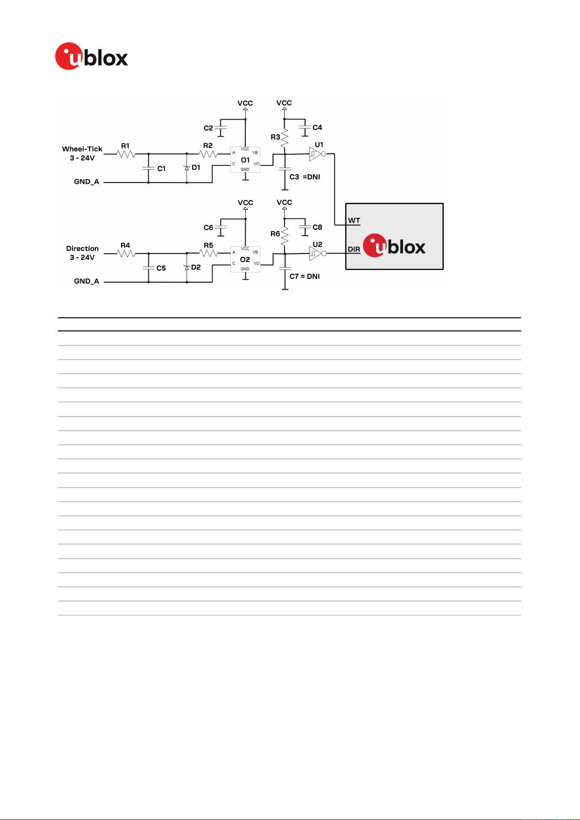
ZED-F9K-Integration manual
Figure 34: Example WT and DIR design
ID Description
R1 RES THICK FILM CHIP 0603 3K3 5% 0.1W
R2 RES THICK FILM CHIP 0603 470R 5% 0.1W
R3 RES THICK FILM CHIP 0603 910R 5% 0.1W
R4 RES THICK FILM CHIP 0603 3K3 5% 0.1W
R5 RES THICK FILM CHIP 0603 470R 5% 0.1W
R6 RES THICK FILM CHIP 0603 910R 5% 0.1W
C1 CAP CER X7R 0603 1N 10% 25V
C2 CAP CER X7R 0603 100N 10% 10V
C3 CAP CER X7R 0603 22N 10% 10V
C4 CAP CER X7R 0603 100N 10% 10V
C5 CAP CER X7R 0603 1N 10% 25V
C6 CAP CER X7R 0603 100N 10% 10V
C7 CAP CER X7R 0603 22N 10% 10V
C8 CAP CER X7R 0603 100N 10% 10V
D1 VOLTAGE REGULATOR DIODE FAIRCHILD BZX84 SOT23 6V2 0.2A
D2 VOLTAGE REGULATOR DIODE FAIRCHILD BZX84 SOT23 6V2 0.2A
O1 OPTOCOUPLER LVTTL/LVCMOS COMPATIBLE AVAGO HCPL-070L-000E SO8
O2 OPTOCOUPLER LVTTL/LVCMOS COMPATIBLE AVAGO HCPL-070L-000E SO8
U1 TINY LOGIC UHS INVERTER WITH SCHMITT TRIGGER FAIRCHILD NC7SZ14 SOT23-5
U2 TINY LOGIC UHS INVERTER WITH SCHMITT TRIGGER FAIRCHILD NC7SZ14 SOT23-5
Table 24: WT and DIR example
4.5 Antenna
TheZED-F9Krequires an active antenna with integral LNA to ensure good performance under
nominal signal reception.
When implementing a custom antenna installation, it is recommended that an OEM active antenna
module be used that meets our specification. Implementing a custom active antenna design is an
UBX-20046189 - R01
C1-Public Early production information
4 Design Page 77 of 105

ZED-F9K-Integration manual
important exercise to meet the required bandwidths and group delay specifications compared to
previous L1-only designs.
Figure 35: u-blox low cost dual-band antenna internal structure
A suitable ground plane is required for the antenna to achieve good performance.
Location of the antenna is critical to reach the stated performance. Unsuitable locations
could include, under vehicle dash, rear-view mirror location, etc.
Dual band active antenna required specifications
Parameter Specification
Antenna type Active antenna
Minimum active antenna gain
Maximum active antenna gain
3
3
17 dB
50 dBActive antenna recommendations
Noise figure <4 dB
L1 band antenna gain
4
L2/E5b band antenna gain
4
1559 - 1606 MHz: 3 dBic typ.
1197 - 1249 MHz: 2 dBic typ.
Polarization RHCP
Axial ratio 2 dB max, at Zenith
Phase center variation <10 mm over elevation/azimuth
Group delay variation in-band
EMI immunity out-of-band
6
Out-of-band 5 rejection
5
10 ns max at each GNSS system bandwidth. Note:
Inter-signal requirement 50 ns max.
30 V/m
40 dB typ
ESD circuit protection 15 kV human body model air discharge
Table 25: Antenna specifications for ZED-F9K modules
3
Including passive losses (filters, cables, connectors etc.)
4
Measured with a ground plane d=150 mm
5
GNSS system bandwidths: 1559… 1563 MHz; 1573… 1578 MHz; 1598… 1606 MHz; 1192… 1212 MHz; 1197… 1217
MHz; 1223… 1231 MHz; 1242… 1249 MHz
6
Exception L1 and L2 bands +/- 200 MHz, emphasis on cellular bands
UBX-20046189 - R01
C1-Public Early production information
4 Design Page 78 of 105
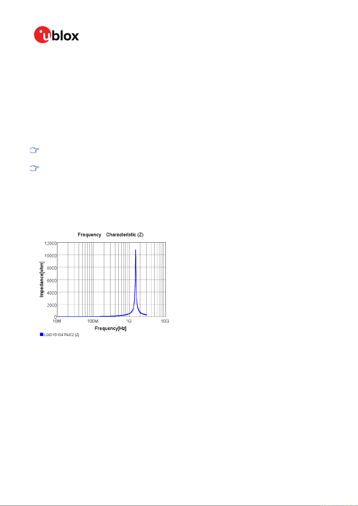
ZED-F9K-Integration manual
The antenna system should include filtering to ensure adequate protection from nearby
transmitters. Take care in the selection of antennas placed close to cellular or Wi-Fi transmitting
antennas.
4.5.1 Antenna bias
Active antennas have an integrated low-noise amplifier that contributes an additional current of
typically 5 to 20 mA to the system's power consumption budget.
If customers do not want to make use of the antenna supervisor function the filtered VCC_RF supply
voltage output can supply the antenna if the supply voltage of the ZED-F9K module matches the
antenna working voltage (e.g. 3.0 V).
A series current limiting resistor is required to prevent short circuits destroying the bias-t
inductor.
The bias-t inductor must be chosen for multi-band operation, a value of 47 nH ±5% is
recommended for the recommended Murata L part. It has a self-resonance frequency of 1
GHz and a high impedance (> 500 Ω) at L band frequencies.
The recommended bias-t inductor (Murata LQG15HS47NJ02) has a maximum current capacity of
300 mA. Hence the current is limited to 70 mA at 3.3V using an active limiter in the recommended
circuit shown in Figure 37 below. A 10 Ω resistor (R2) is provided to measure the current. This resistor
power rating must be chosen to ensure reliability in the chosen circuit design.
Figure 36: ZED-F9K antenna bias inductor impedance
A recommended circuit design for an active antenna bias is shown below. This example shows an
external voltage of 3.3 V with current limiting as described above. An ESD protection diode should
also be connected to the input as shown.
UBX-20046189 - R01
C1-Public Early production information
4 Design Page 79 of 105

ZED-F9K-Integration manual
Figure 37: ZED-F9K reference design for antenna bias
L1: Murata LQG15HS47NJ02 0402 47 N 5% 0.30 A -55/+125 C
D1: TYCO, 0.25PF, PESD0402-140 -55/+125C
C3: MURATA GRM033R61E104KE14 CER X5R 0201 100N 10% 25V
R2: RES THICK FILM CHIP 1206 10R 5% 0.25W
It is recommended to use active current limiting. If active current limiting is not used, the important
points covered below need to be taken into account:
Figure 38: ZED-F9K VCC_RF antenna bias
The bias-t inductor and current limiting resistor must be selected to be reliable with a shortcircuit on the antenna feed if no active current limiter is used. Our recommended part has
a limit of 300 mA. A part with a higher current capability will be needed if the short circuit
current is as described here. This will also be affected by the voltage level of the antenna
UBX-20046189 - R01
C1-Public Early production information
4 Design Page 80 of 105
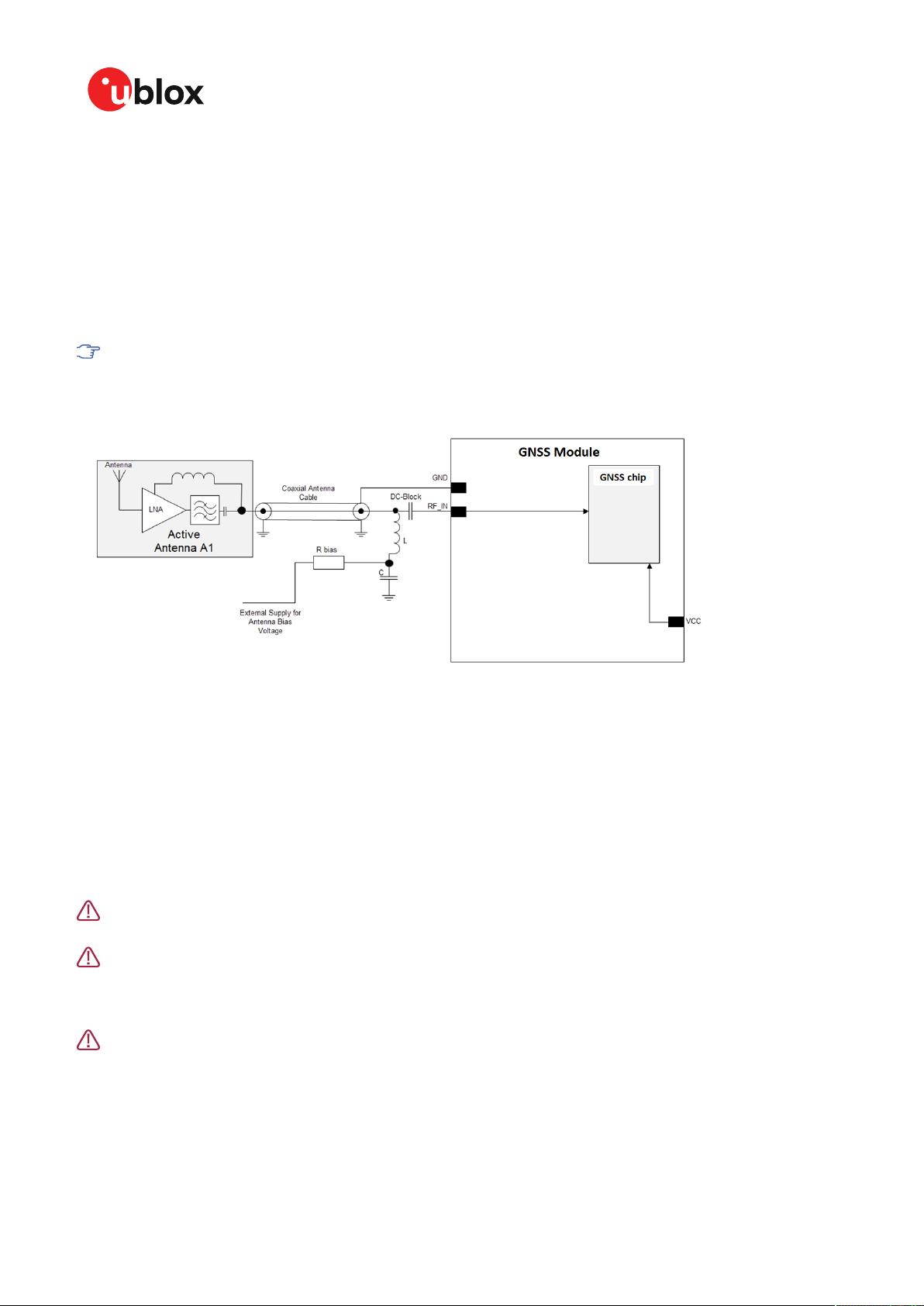
ZED-F9K-Integration manual
bias supply due to power dissipation. Take the current limit capability of the antenna bias
supply into consideration. In the case where the module supplies the voltage via VCC_RF, a
higher value resistor will be needed to ensure the module supply inductor is protected. The
current should be limited to below 150 mA at the module supply voltage under short-circuit
conditions. In this case a value of 17 Ω or more is required at a module supply of 3 V to limit
short circuit current to 150 mA. The DC resistance of the bias-t inductor is assumed to be
1-2 Ω and the module internal feed inductor is assumed to be 1.2 Ω.
If the VCC_RF voltage does not match with the supply voltage of the active antenna, use a filtered
external supply.
The power dissipation in the resistor and inductor needs to be taken into account based on
the supply voltage and short circuit current. The bias-t inductor current capability and the
bias resistor value need to be calculated as shown above. The supply voltage for the bias-t
and its current capability is part of the calculation.
Figure 39: ZED-F9K external voltage antenna bias
4.6 EOS/ESD precautions
When integrating GNSS receivers into wireless systems, careful consideration must be given to
electromagnetic and voltage susceptibility issues. Wireless systems include components which
can produce Electrostatic Discharge (ESD), Electrical Overstress (EOS) and Electro-Magnetic
Interference (EMI). CMOS devices are more sensitive to such influences because their failure
mechanism is defined by the applied voltage, whereas bipolar semiconductors are more susceptible
to thermal overstress. The following design guidelines are provided to help in designing robust yet
cost-effective solutions.
To avoid overstress damage during production or in the field it is essential to observe strict
EOS/ESD/EMI handling and protection measures.
To prevent overstress damage at the RF_IN of your receiver, never exceed the maximum
input power as specified in the u-blox ZED-F9K Data sheet [1].
4.6.1 ESD protection measures
GNSS receivers are sensitive to Electrostatic Discharge (ESD). Special precautions are
required when handling. Most defects caused by ESD can be prevented by following strict
ESD protection rules for production and handling. When implementing passive antenna
patches or external antenna connection points, then additional ESD measures as shown in
the figure below can also avoid failures in the field.
UBX-20046189 - R01
C1-Public Early production information
4 Design Page 81 of 105

ZED-F9K-Integration manual
Figure 40: RF ESD precautions
4.6.2 EOS precautions
Electrical overstress (EOS) usually describes situations when the maximum input power exceeds
the maximum specified ratings. EOS failure can happen if RF emitters are close to a GNSS receiver
or its antenna. EOS causes damage to the chip structures. If the RF_IN is damaged by EOS, it is hard
to determine whether the chip structures have been damaged by ESD or EOS.
EOS protection measures as shown in the figure below are recommended for any designs combining
wireless communication transceivers (e.g. GSM, GPRS) and GNSS in the same design or in close
proximity.
Figure 41: Active antenna EOS protection
4.6.3 Safety precautions
The ZED-F9K must be supplied by an external limited power source in compliance with the clause
2.5 of the standard IEC 60950-1. In addition to external limited power source, only Separated or
Safety Extra-Low Voltage (SELV) circuits are to be connected to the module including interfaces and
antennas.
For more information about SELV circuits see section 2.2 in Safety standard IEC 60950-1.
4.7 Electromagnetic interference on I/O lines
Any I/O signal line with a length greater than approximately 3 mm can act as an antenna and may
pick up arbitrary RF signals transferring them as noise into the receiver. This specifically applies to
unshielded lines, in which the corresponding GND layer is remote or missing entirely, and lines close
to the edges of the printed circuit board.
If, for example, a cellular signal radiates into an unshielded high-impedance line, it is possible to
generate noise in the order of volts and not only distort receiver operation but also damage it
UBX-20046189 - R01
C1-Public Early production information
4 Design Page 82 of 105

ZED-F9K-Integration manual
permanently. Another type of interference can be caused by noise generated at the PIO pins that
emits from unshielded I/O lines. Receiver performance may be degraded when this noise is coupled
into the GNSS antenna.
EMI protection measures are particularly useful when RF emitting devices are placed next to the
GNSS receiver and/or to minimize the risk of EMI degradation due to self-jamming. An adequate
layout with a robust grounding concept is essential in order to protect against EMI.
Intended Use: In order to mitigate any performance degradation of a radio equipment under
EMC disturbance, system integration shall adopt appropriate EMC design practice and not
contain cables over three meters on signal and supply ports.
4.7.1 General notes on interference issues
Received GNSS signal power at the antenna is very low. At the nominal received signal strength (-128
dBm) it is below the thermal noise floor of -111 dBm. Due to this fact, a GNSS receiver is susceptible
to interference from nearby RF sources of any kind. Two cases can be distinguished:
• Out-of-band interference: Typically any kind of wireless communications system (e.g. LTE,
GSM, CDMA, 3G, WLAN, Bluetooth, etc.) may emit its specified maximum transmit power in
close proximity to the GNSS receiving antenna, especially if such a system is integrated with
the GNSS receiver. Even at reasonable antenna selectivity, destructive power levels may reach
the RF input of the GNSS receiver. Also, larger signal interferers may generate intermodulation
products inside the GNSS receiver front-end that fall into the GNSS band and contribute to inband interference.
• In-band interference: Although the GNSS band is kept free from intentional RF signal sources
by radio-communications standards, many devices emit RF power into the GNSS band at levels
much higher than the GNSS signal itself. One reason is that the frequency band above 1 GHz
is not well regulated with regards to EMI, and even if permitted, signal levels are much higher
than GNSS signal power. Notably, all types of digital equipment, such as PCs, digital cameras,
LCD screens, etc. tend to emit a broad frequency spectrum up to several GHz of frequency. Also
wireless transmitters may generate spurious emissions that fall into GNSS band.
As an example, GSM uses power levels of up to 2 W (+33 dBm). The absolute maximum power
input at the RF input of the GNSS receiver can be +15 dBm. The GSM specification allows spurious
emissions for GSM transmitters of up to +36 dBm, while the GNSS signal is less than -128
dBm. By simply comparing these numbers it is obvious that interference issues must be seriously
considered in any design of a GNSS receiver. Different design goals may be achieved through
different implementations:
• The primary focus is to prevent damaging the receiver from large input signals. Here the
GNSS performance under interference conditions is not important and suppression of the
signal is permitted. It is sufficient to just observe the maximum RF power ratings of all of the
components in the RF input path.
• GNSS performance must be guaranteed even under interference conditions. In such a case,
not only the maximum power ratings of the components in the receiver RF path must be
observed. Further, non-linear effects like gain compression, NF degradation (desensitization)
and intermodulation must be analyzed.
Pulsed interference with a low-duty cycle such as GSM may be destructive due to the high
peak power levels.
4.7.2 In-band interference mitigation
With in-band interference, the signal frequency is very close to the GNSS frequency. Such
interference signals are typically caused by harmonics from displays, micro-controller operation, bus
systems, etc. Measures against in-band interference include:
UBX-20046189 - R01
C1-Public Early production information
4 Design Page 83 of 105

ZED-F9K-Integration manual
• Maintaining a good grounding concept in the design
• Shielding
• Layout optimization
• Low-pass filtering of noise sources, e.g. digital signal lines
• Remote placement of the GNSS antenna, far away from noise sources
• Adding an LTE, CDMA, GSM, WCDMA, BT band-pass filter before antenna
4.7.3 Out-of-band interference
Out-of-band interference is caused by signal frequencies that are different from the GNSS carrier
frequency. The main sources are wireless communication systems such as LTE, GSM, CDMA,
WCDMA, Wi-Fi, BT, etc.
Measures against out-of-band interference include maintaining a good grounding concept in the
design and adding a GNSS band-pass filter into the antenna input line to the receiver.
For GSM applications, such as typical handset design, an isolation of approximately 20 dB can be
reached with careful placement of the antennas. If this is insufficient, an additional SAW filter is
required on the GNSS receiver input to block the remaining GSM transmitter energy.
4.8 Layout
This section details layout and placement requirements of the ZED-F9K high precision receiver.
4.8.1 Placement
GNSS signals at the surface of the Earth are below the thermal noise floor. A very important factor in
achieving maximum GNSS performance is the placement of the receiver on the PCB. The placement
used may affect RF signal loss from antenna to receiver input and enable interference into the
sensitive parts of the receiver chain, including the antenna itself. When defining a GNSS receiver
layout, the placement of the antenna with respect to the receiver, as well as grounding, shielding and
interference from other digital devices are crucial issues and need to be considered very carefully.
Signal loss on the RF connection from antenna to receiver input must be minimized as much as
possible. Hence, the connection to the antenna must be kept as short as possible.
Ensure that RF critical circuits are clearly separated from any other digital circuits on the system
board. To achieve this, position the receiver digital part closer to the digital section of the system
PCB and have the RF section and antenna placed as far as possible away from the other digital
circuits on the board.
A proper GND concept shall be followed: The RF section shall not be subject to noisy digital supply
currents running through its GND plane.
4.8.2 Thermal management
During design-in do not place the receiver near sources of heating or cooling. The receiver oscillator
is sensitive to sudden changes in ambient temperature which can adversely impact satellite signal
tracking. Sources can include co-located power devices, cooling fans or thermal conduction via the
PCB. Take into account the following questions when designing in the receiver.
• Is the receiver placed away from heat sources?
• Is the receiver placed away from air-cooling sources?
• Is the receiver shielded by a cover/case to prevent the effects of air currents and rapid
environmental temperature changes?
UBX-20046189 - R01
C1-Public Early production information
4 Design Page 84 of 105
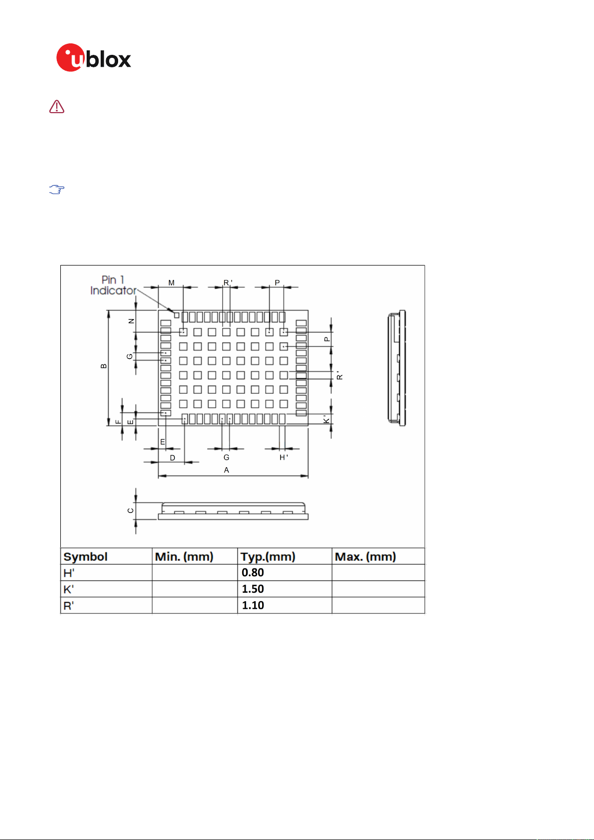
ZED-F9K-Integration manual
High temperature drift and air vents can affect the GNSS performance. For best
performance, avoid high temperature drift and air vents near the receiver.
4.8.3 Package footprint, copper and paste mask
Copper and solder mask dimensioning recommendations for the ZED-F9K module packages are
provided in this section.
These are recommendations only and not specifications. The exact copper, solder and paste
mask geometries, distances, stencil thickness and solder paste volumes must be adapted
to the specific production processes (e.g. soldering etc.) of the customer.
Refer to the ZED-F9K Data sheet [1] for the mechanical dimensions.
4.8.3.1 Footprint
Figure 42: ZED-F9K suggested footprint (i.e. copper mask)
UBX-20046189 - R01
C1-Public Early production information
4 Design Page 85 of 105

4.8.3.2 Paste mask
ZED-F9K-Integration manual
Figure 43: ZED-F9K suggested paste mask
4.8.4 Layout guidance
The presented layout guidance reduces the risk of performance issues at design level.
4.8.4.1 RF In trace
The RF in trace has to work in the combined GNSS signal bands.
For FR-4 PCB material with a dielectric permittivity of for example 4.7, the trace width for the 50 Ω
line impedance can be calculated.
A grounded co-planar RF trace is recommended as it provides the maximum shielding from noise
with adequate vias to the ground layer.
The RF trace must be shielded by vias to ground along the entire length of the trace and the ZEDF9K RF_IN pad should be surrounded by vias as shown in the figure below.
UBX-20046189 - R01
C1-Public Early production information
4 Design Page 86 of 105

ZED-F9K-Integration manual
Figure 44: RF input trace
The RF_IN trace on the top layer should be referenced to a suitable ground layer.
4.8.4.2 Vias for the ground pads
The ground pads under the ZED-F9K high precision receiver need to be grounded with vias to the
lower ground layer of the PCB. A solid ground layer fill on the top layer of the PCB is recommended.
This is shown in the figure below.
Figure 45: Top layer fill and vias
4.8.4.3 VCC pads
The VCC pads for the ZED-F9K high precision receiver must have as low impedance as possible with
large vias to the lower power layer of the PCB. The VCC pads need a large combined pad and the decoupling capacitors must be placed as close as possible. This is shown in the figure below.
UBX-20046189 - R01
C1-Public Early production information
4 Design Page 87 of 105

Figure 46: VCC pads
4.9 Design guidance
4.9.1 General considerations
Check power supply requirements and schematic:
ZED-F9K-Integration manual
• Is the power supply voltage within the specified range and noise-free?
• If USB is not used, connect the V_USB pin to ground.
• It is recommended to have a separate LDO for V_USB that is enabled by the module VCC. This is
to comply with the USB self-powered specification.
• If USB is used, is there a 1 uF capacitor right near the V_USB pin? This is just for the V_USB pin.
• Is there a 1 uF cap right next to the module VCC pin?
• Compare the peak current consumption of the ZED-F9K GNSS module with the specification of
your power supply.
• GNSS receivers require a stable power supply. Avoid series resistance (less than 0.2 Ω) in
your power supply line (the line to VCC) to minimize the voltage ripple on VCC. See the ZEDF9K Power supply section in the Design chapter for more information on the power supply
requirements.
• Allow all I/O to Float/High impedance (High-Z) when VCC is not applied.
4.9.2 Backup battery
Check backup supply requirements and schematic:
• For achieving a minimal time to first fix (TTFF) after a power down (warm starts, hot starts),
make sure to connect a backup battery to V_BCKP.
• Verify your battery backup supply can provide the battery backup current specified in the ZED-
F9K data sheet.
• Allow all I/O including UART and other interfaces to Float/High impedance in HW backup mode
(battery backup connected with VCC removed).
4.9.3 RF front-end circuit options
It is important that the RF input is fed by an active antenna meeting the requirements for
the ZED-F9K.
The first stages of the signal processing chain are crucial to the overall receiver performance.
When an RF input connector is employed this can provide a conduction path for harmful or
destructive electrical signals. If this is a likely factor the RF input should be protected accordingly.
UBX-20046189 - R01
C1-Public Early production information
4 Design Page 88 of 105

ZED-F9K-Integration manual
Additional points on the RF input
• What is the expected quality of the signal source (antenna)?
• What is the external active antenna signal power?
• What is the bandwidth and filtering of the external active antenna?
• Does the external antenna and filtering components meet the group delay variation
requirements? This is critical for RTK.
Are destructive RF power levels expected to reach the RF input? Is interference from wireless
transmitters expected?
• What are the characteristics of these signals (duty cycle, frequency range, power range,
spectral purity)?
• What is the expected GNSS performance under interference conditions?
Is there a risk of RF input exposure to excessive ESD stress?
• In the field: Can the user access the antenna connector?
• PCB / system assembly: Is there risk that statically charged parts (e.g. patch antennas) may be
discharged through the RF input?
The following subsections provide several options addressing the various questions above:
In some applications, such as cellular transceivers, interference signals may exceed the
maximum power rating of the RF_IN input. To avoid device destruction use of external input
protection is mandatory.
During assembly of end-user devices which contain passive patch antennas, an ESD
discharge may occur during production when pre-charged antennas are soldered to the
GNSS receiver board. In such cases, use of external protection in front of RF_IN is mandatory
to avoid device destruction.
ESD discharge cannot be avoided during assembly and / or field use. Note that SAW filters are
susceptible to ESD damage. To provide additional robustness an ESD protection diode may be
placed at the antenna RF connector to GND.
4.9.4 Antenna/RF input
Check RF input requirements and schematic:
• An OEM active antenna module that meets our requirements should be used if there is a need
to integrate the antenna.
• The total maximum noise figure including external LNA (or the LNA in the active antenna)
should be around 3 dB.
• Ensure active antenna gain is ideally between 30 - 40 dB gain.
• Make sure the antenna is not placed close to noisy parts of the circuitry and does not face any
other noisy elements (for example micro-controller, display).
• Signal levels above 40 C/N0 average are required for optimal RTK performance.
• If a patch type antenna is used, an antenna ground plane with minimum 100 - 150 mm
diameter is required.
• Ensure antenna supports both L1 and L2 bands.
• Ensure antenna element gain is between 2 and 3 dBic typical for L1 and L2 bands.
• Ensure the group delay variation including active antenna is 10 ns max at each GNSS system
bandwidth. Note: Inter-signal requirement 50 ns max.
• ESD protection on the RF input is mandatory.
• Bias-t inductor must be L1 and L2 band frequency selected with high impedance in the GNSS
band.
UBX-20046189 - R01
C1-Public Early production information
4 Design Page 89 of 105

ZED-F9K-Integration manual
• Ensure RF trace is tuned for 50 Ω to ensure L1 and L2 bandwidth.
4.9.5 Ground pads
Ensure the ground pads of the module are connected to ground.
4.9.6 Schematic design
For a minimal design with the ZED-F9K GNSS modules, consider the following functions and pins:
• Connect the power supply to VCC and V_BCKP.
• V_USB: If USB is used it is recommended V_USB is to be powered as per USB self-powered mode
specification.
• If USB is not used connect V_USB to ground.
• Ensure an optimal ground connection to all ground pins of the ZED-F9K GNSS module.
• Choose the required serial communication interfaces (UART, USB, SPI or I2C) and connect the
appropriate pins to your application.
• If you need hot or warm start in your application, connect a backup battery to V_BCKP.
• Antenna bias is required, see ZED-F9K antenna bias section.
4.9.7 Layout design-in guideline
• Is the receiver placed away from heat sources?
• Is the receiver placed away from air-cooling sources?
• Is the receiver shielded by a cover/case to prevent the effects of air currents and rapid
environmental temperature changes?
• Is the receiver placed as recommended in the Layout and Layout guidance?
• Assure a low serial resistance on the VCC power supply line (choose a line width > 400 um).
• Keep the power supply line as short as possible.
• Add a ground plane underneath the module to reduce interference. This is especially important
for the RF input line.
• For improved shielding, add as many vias as possible around the micro strip/co-planar
waveguide, around the serial communication lines, underneath the module, etc.
UBX-20046189 - R01
C1-Public Early production information
4 Design Page 90 of 105

ZED-F9K-Integration manual
5 Product handling
5.1 ESD handling precautions
ZED-F9K contains highly sensitive electronic circuitry and is an Electrostatic Sensitive
Device (ESD). Observe precautions for handling! Failure to observe these precautions can
result in severe damage to the GNSS receiver!
•
Unless there is a galvanic coupling between the local
GND (i.e. the work table) and the PCB GND, then the first
point of contact when handling the PCB must always be
between the local GND and PCB GND.
•
Before mounting an antenna patch, connect ground of the
device.
•
When handling the RF pin, do not come into contact with
any charged capacitors and be careful when contacting
materials that can develop charges (e.g. patch antenna
~10 pF, coax cable ~50-80 pF/m or soldering iron).
•
To prevent electrostatic discharge through the RF input,
do not touch any exposed antenna area. If there is any risk
that such exposed antenna area is touched in non-ESD
protected work area, implement proper ESD protection
measures in the design.
•
When soldering RF connectors and patch antennas to the
receiver’s RF pin, make sure to use an ESD-safe soldering
iron (tip)
5.2 Soldering
Soldering paste
Use of “no clean” soldering paste is highly recommended, as it does not require cleaning after the
soldering process. The paste in the example below meets these criteria.
• Soldering paste: OM338 SAC405 / Nr.143714 (Cookson Electronics)
• Alloy specification: Sn 95.5/ Ag 4/ Cu 0.5 (95.5% tin/ 4% silver/ 0.5% copper)
• Melting temperature: 217 °C
• Stencil thickness: The exact geometry, distances, stencil thicknesses and solder paste
volumes must be adapted to the customer's specific production processes (e.g. soldering).
Reflow soldering
A convection-type soldering oven is highly recommended over the infrared-type radiation oven.
Convection-heated ovens allow precise control of the temperature, and all parts will heat up evenly,
regardless of material properties, thickness of components and surface color.
UBX-20046189 - R01
C1-Public Early production information
5 Product handling Page 91 of 105

ZED-F9K-Integration manual
As a reference, see “IPC-7530 Guidelines for temperature profiling for mass soldering (reflow and
wave) processes”, published in 2001.
Preheat phase
During the initial heating of component leads and balls, residual humidity will be dried out. Note that
the preheat phase does not replace prior baking procedures.
• Temperature rise rate: max 3 °C/s. If the temperature rise is too rapid in the preheat phase,
excessive slumping may be caused
• Time: 60 – 120 s. If the preheat is insufficient, rather large solder balls tend to be generated.
Conversely, if performed excessively, fine balls and large balls will be generated in clusters
• End temperature: 150 – 200 °C. If the temperature is too low, non-melting tends to be caused in
areas containing large heat capacity
Heating - reflow phase
The temperature rises above the liquidus temperature of 217 °C. Avoid a sudden rise in temperature
as the slump of the paste could become worse.
• Limit time above 217 °C liquidus temperature: 40 – 60 s
• Peak reflow temperature: 245 °C
Cooling phase
A controlled cooling prevents negative metallurgical effects of the solder (solder becomes more
brittle) and possible mechanical tensions in the products. Controlled cooling helps to achieve bright
solder fillets with a good shape and low contact angle.
• Temperature fall rate: max 4 °C/s
To avoid falling off, the modules should be placed on the topside of the motherboard during
soldering.
The final soldering temperature chosen at the factory depends on additional external factors such
as the choice of soldering paste, size, thickness and properties of the base board, etc. Exceeding the
maximum soldering temperature in the recommended soldering profile may permanently damage
the module.
Figure 47: Soldering profile
UBX-20046189 - R01
C1-Public Early production information
5 Product handling Page 92 of 105
ZED-F9K-Integration manual
Modules must not be soldered with a damp heat process.
Optical inspection
After soldering the module, consider optical inspection.
Cleaning
Do not clean with water, solvent, or ultrasonic cleaner:
• Cleaning with water will lead to capillary effects where water is absorbed into the gap between
the baseboard and the module. The combination of residues of soldering flux and encapsulated
water leads to short circuits or resistor-like interconnections between neighboring pads.
• Cleaning with alcohol or other organic solvents can result in soldering flux residues flowing
underneath the module, into areas that are not accessible for post-cleaning inspections. The
solvent will also damage the sticker and the printed text.
• Ultrasonic cleaning will permanently damage the module, in particular the quartz oscillators.
The best approach is to use a "no clean" soldering paste and eliminate the cleaning step after the
soldering.
Repeated reflow soldering
Repeated reflow soldering processes or soldering the module upside down are not
recommended.
A board that is populated with components on both sides may require more than one reflow
soldering cycle. In such a case, the process should ensure the module is only placed on the board
submitted for a single final upright reflow cycle. A module placed on the underside of the board may
detach during a reflow soldering cycle due to lack of adhesion.
The module can also tolerate an additional reflow cycle for re-work purposes.
Wave soldering
Base boards with combined through-hole technology (THT) components and surface-mount
technology (SMT) devices require wave soldering to solder the THT components. Only a single wave
soldering process is encouraged for boards populated with modules.
Rework
We do not recommend using a hot air gun because it is an uncontrolled process and can damage
the module.
Use of a hot air gun can lead to overheating and severely damage the module. Always avoid
overheating the module.
After the module is removed, clean the pads before re-applying solder paste, placing and reflow
soldering a new module.
Never attempt a rework on the module itself, e.g. by replacing individual components. Such
actions will immediately void the warranty.
Conformal coating
Certain applications employ a conformal coating of the PCB using HumiSeal® or other related
coating products. These materials affect the RF properties of the GNSS module and it is important
to prevent them from flowing into the module. The RF shields do not provide 100% protection for
the module from coating liquids with low viscosity. Apply the coating carefully.
Conformal coating of the module will void the warranty.
UBX-20046189 - R01
C1-Public Early production information
5 Product handling Page 93 of 105
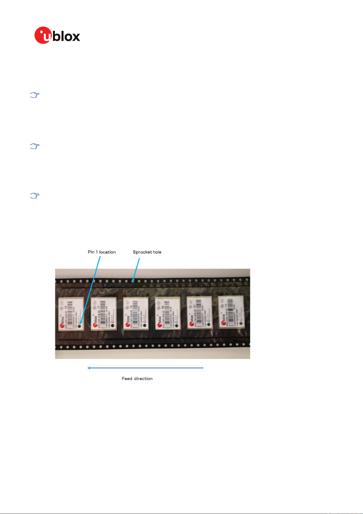
ZED-F9K-Integration manual
Casting
If casting is required, use viscose or another type of silicon pottant. The OEM is strongly advised to
qualify such processes in combination with the module before implementing this in the production.
Casting will void the warranty.
Grounding metal covers
Attempts to improve grounding by soldering ground cables, wick or other forms of metal strips
directly onto the EMI covers is done at the customer’s own risk. The numerous ground pins should
be sufficient to provide optimum immunity to interferences and noise.
u-blox makes no warranty for damages to the module caused by soldering metal cables or
any other forms of metal strips directly onto the EMI covers.
Use of ultrasonic processes
Some components on the module are sensitive to ultrasonic waves. Use of any ultrasonic processes
(cleaning, welding etc.) may cause damage to the GNSS receiver.
u-blox offers no warranty against damages to the module caused by ultrasonic processes.
5.3 Tapes
Figure 48 shows the feed direction and illustrates the orientation of the ZED-F9Ks on the tape: (F9P
reel shown for illustrative purposes).
Figure 48: Orientation of ZED-F9K on the tape
The feed direction to the pick and place pick-up is shown by the orientation of the pin 1 location. In
Figure 48, with pin 1 location on the bottom of the tape, the feed direction into the pick and place
pick-up is from the reel (located on the right of the figure) towards left.
The dimensions of the tapes for ZED-F9K are specified in Figure 49 (measurements in mm).
UBX-20046189 - R01
C1-Public Early production information
5 Product handling Page 94 of 105

ZED-F9K-Integration manual
Figure 49: ZED-F9K tape dimensions (mm)
5.4 Reels
The ZED-F9K receivers are deliverable in quantities of 250 pieces on a reel. The receivers are shipped
on reel type B, as specified in the u-blox Package Information Guide [3].
5.5 Moisture sensitivity levels
The moisture sensitivity level (MSL) for ZED-F9K is specified in the table below.
Package MSL level
LGA 4
Table 26: MSL level
For MSL standard see IPC/JEDEC J-STD-020, which can be downloaded from
www.jedec.org.
For more information regarding moisture sensitivity levels, labeling, storage and drying, see
the u-blox Package Information Guide [3].
UBX-20046189 - R01
C1-Public Early production information
5 Product handling Page 95 of 105

Appendix
A Glossary
Abbreviation Definition
ADR Automotive dead reckoning
ANSI American National Standards Institute
ARP Antenna reference point
BeiDou Chinese navigation satellite system
BBR Battery-backed RAM
CDMA Code-division multiple access
CRP Configurable reference point
EMC Electromagnetic compatibility
EMI Electromagnetic interference
EOS Electrical overstress
EPA Electrostatic protective area
ESD Electrostatic discharge
Galileo European navigation satellite system
GLONASS Russian navigation satellite system
GND Ground
GNSS Global navigation satellite system
GPS Global Positioning System
GSM Global System for Mobile Communications
I2C Inter-integrated circuit bus
IEC International Electrotechnical Commission
IMU Inertial measurement unit
IRP Inertial measurement unit reference point
ITRF International Terrestrial Reference Frame
MSM Multiple signal messages
NTRIP Networked transport of RTCM via internet protocol
PCB Printed circuit board
QZSS Quasi-Zenith Satellite System
RF Radio frequency
RTCM Radio Technical Commission for Maritime Services
RTK Real-time kinematic
SBAS Satellite-based Augmentation System
SV Space vehicle, a satellite
TDOP Time dilution of precision
UBX u-blox
UDR Untethered dead reckoning
VRP Vehicle reference point
ZED-F9K-Integration manual
UBX-20046189 - R01
C1-Public Early production information
Appendix Page 96 of 105

ZED-F9K-Integration manual
B Reference frames
Real time kinematic (RTK) is a differential system where the rover uses the corrections from a
reference station or a reference station network. The rover receiver will calculate its position in the
reference frame used by the service provider in its correction stream. If the output is required in a
different reference frame, then a (custom) datum transformation is required.
For example, if an application requires the position in the ITRF14 reference frame but the correction
service is using the ETRF14 reference frame - to which the RTK solution will also be referring - then
this reference frame offset needs to be compensated. For example if utilizing a truth system which
is using corrections referring to different reference frame, it is important to compensate for the
reference frame offset to avoid systematic errors in the analysis.
Terrestrial reference system is a coordinate reference system which is rotating in space with the
rotation of the Earth. The reference system is an abstract concept that is realized by obtaining
coordinates for some points on the surface of the Earth. This kind of realization is called a reference
frame. For more details, see for example ITRF web page. Commonly used reference systems include
Internation Terrestrial Reference System (ITRS) and European Terrestrial Reference System 1989
(ETRS89).
Widely used reference frames include for example International Terrestrial Reference Frame (ITRF)
and European Terrestrial Reference Frame (ETRF). ITRF is a realization of ITRS, done every few years.
Latest realizations of ITRF are ITRF2008 and ITRF2014. ETRF is a realization of ETRS89, done every
few years. Latest realizations are ITRF2005 and ETRF2014.
For example, the EUREF is used to realize the ETRS89. For information, see their homepage: EUREF.
See the ITRF website for more information and an online transform calculator: ITRF.
Another online tool for transformations is available on the EUREF network page: EUREF
Transformation.
Reference frames can have constant offsets between each other but, in addition to that, they can
also drift and rotate with respect to each other. One major reason for this is that the tectonic plates
move constantly and the reference frames that are attached to the tectonic plates move along with
the plates.
The ZED-F9K stores the EGM96 geoid model with limited resolution, leading to degraded
precision of the reported mean sea level height and geoid separation. If the user application
needs higher geoid separation accuracy, it is required to apply its own adjustment to the
ellipsoidal height output from the ZED-F9K.
C RTK configuration procedures with u-center
This section provides some guidance for using u-center to evaluate ZED-F9K RTK operation.
C.1 Receiver configuration with u-center
In this example, UART1 is configured to use a suitable baud rate for communicating with a host
PC running u-center. A set of output messages are enabled so that the receiver status can be
monitored.
Using the UBX-CFG-VALSET configuration window, set the UART1 interface for the correct host
baud rate:
UBX-20046189 - R01
C1-Public Early production information
Appendix Page 97 of 105
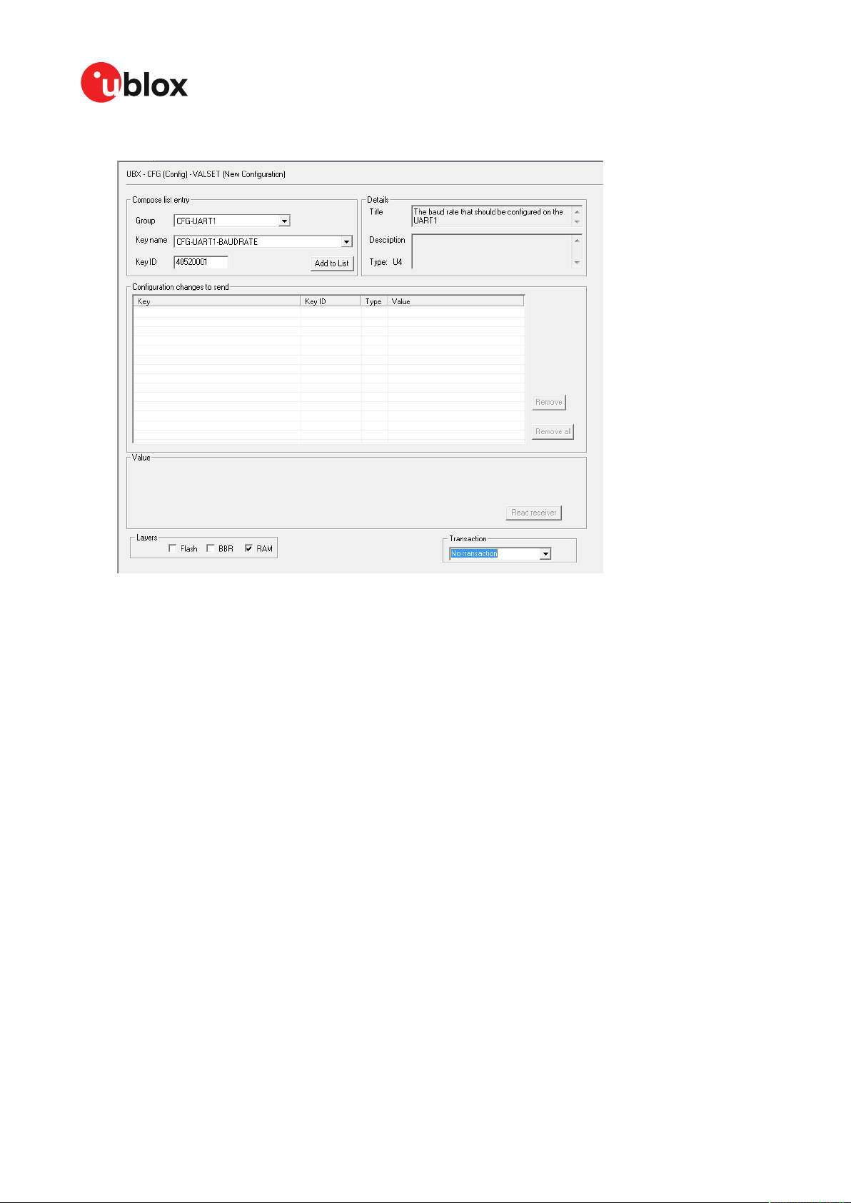
ZED-F9K-Integration manual
1. Select Group: CFG-UART1, Key name: CFG-UART1-BAUDRATE. See Figure 50.
Figure 50: u-center UBX-CFG-VALSET message view
2. Select Add to List, it will appear in the table below.
UBX-20046189 - R01
C1-Public Early production information
Appendix Page 98 of 105

ZED-F9K-Integration manual
3. Select the added key. It will now give the option of setting or reading the current value. See
Figure 51.
Figure 51: Example u-center UBX-CFG-VALSET message view when selecting a configuration item
4. Add the value, for example, 230400 into the "Value" window that appears below the list. See
Figure 52.
UBX-20046189 - R01
C1-Public Early production information
Appendix Page 99 of 105

ZED-F9K-Integration manual
5. Set the configuration by clicking the Send button at the bottom of the message tree view.
Remember to set the u-center baud rate to match the value set in the receiver.
Figure 52: u-center UBX-CFG-VALSET message view for setting the CFG-UART1-BAUDRATE configuration item
that controls the baudrate of UART1
Next, some UBX example messages are configured to enable viewing the receiver status.
1. Select Group: CFG-MSGOUT, Key name: CFG-MSGOUT-UBX, and select the UART1 required
messages.
2. Add each message to the list, setting the value of each to 1.
UBX-20046189 - R01
C1-Public Early production information
Appendix Page 100 of 105
 Loading...