

Page 1
Fieldbus Independent
I/O Modules
Bluetooth
750-644
®
RF Transceiver
Manual
Version 1.0.1
Page 2

2 • General
Copyright © 2008 by WAGO Kontakttechnik GmbH & Co. KG
All rights reserved.
WAGO Kontakttechnik GmbH & Co. KG
Hansastraße 27
D-32423 Minden
Phone: +49 (0) 571/8 87 – 0
Fax: +49 (0) 571/8 87 – 1 69
E-Mail: info@wago.com
Web:
http://www.wago.com
Technical Support
Phone: +49 (0) 571/8 87 – 5 55
Fax: +49 (0) 571/8 87 – 85 55
E-Mail:
support@wago.com
Every conceivable measure has been taken to ensure the correctness and completeness of this documentation. However, as errors can never be fully excluded, we would appreciate any information or ideas at any time.
E-Mail: documentation@wago.com
We wish to point out that the software and hardware terms as well as the
trademarks of companies used and/or mentioned in the present manual are
generally trademark or patent protected.
WAGO-I/O-SYSTEM 750
I/O Modules
Page 3

Important Comments • 3
Legal Principles
Content
1 Important Comments ................................................................................. 7
1.1 Legal Principles........................................................................................7
1.1.1 Copyright............................................................................................. 7
1.1.2 Personnel Qualification .......................................................................
1.1.3 Intended Use........................................................................................
1.2 Symbols....................................................................................................8
1.3 Number Notation......................................................................................8
1.4 Safety Notes ............................................................................................. 9
1.5 Scope ........................................................................................................7
2 I/O Modules ...............................................................................................10
2.1 Special Modules ..................................................................................... 10
2.1.1 750-644 [Bluetooth® RF Transceiver]...............................................10
2.1.1.1 View..............................................................................................10
2.1.1.2 Description....................................................................................10
2.1.1.3 Indicators.......................................................................................13
2.1.1.4 Schematic Diagram.......................................................................15
2.1.1.5 Technical Data ..............................................................................15
2.1.1.6 Function Description..................................................................... 17
2.1.1.7 Operating Modes........................................................................... 21
2.1.1.8 Process Image ...............................................................................31
7
7
3 Configuration of a Bluetooth® Piconet ....................................................58
4 Tools for Configuring and Operating .....................................................60
4.1 Configuring and Operating with WAGO-I/O-CHECK..........................61
4.1.1 User Interface ....................................................................................
4.1.1.1 Title Bar ........................................................................................
4.1.1.2 Symbol Bar ...................................................................................
61
62
62
4.1.1.3 Navigation.....................................................................................63
4.1.1.4 Mode Assignment .........................................................................
4.1.1.5 Parameterization Area...................................................................
4.1.1.6 Status Display ...............................................................................
®
4.2 Configuring the Bluetooth
4.2.1 Setting the Bluetooth
Module 750-644 ........................................78
®
Process Data and Mailbox Size..................... 78
64
65
77
4.2.2 Setting the Mode................................................................................ 78
4.2.3 Role Assignment (Master/Slave).......................................................79
4.2.4 Search for and Display Devices within Range .................................. 79
4.2.5 Bind new Devices.............................................................................. 79
4.2.5.1 Entering Bluetooth® Devices manually ........................................79
®
4.2.5.2 Bind Bluetooth
4.2.6 Assigning Slave Process Data to Slots in the Master........................
Devices from Network Search........................... 80
81
4.2.7 Diagnostics ........................................................................................81
WAGO-I/O-SYSTEM 750
I/O Modules
Page 4

4 • Important Comments
Legal Principles
5 Fieldbus-specific Additions ......................................................................82
5.1 CANopen................................................................................................82
5.1.1 Process Image Access........................................................................ 82
5.1.1.1 Example ........................................................................................83
5.2 DeviceNet............................................................................................... 86
5.2.1 Process Image Access........................................................................ 86
5.2.1.1 Example ........................................................................................86
5.3 ETHERNET ........................................................................................... 88
5.3.1 Process Image Access........................................................................ 88
5.3.1.1 MODBUS Protocol....................................................................... 88
5.3.1.2 EtherNet/IP Protocol..................................................................... 90
5.4 PROFIBUS-DP.......................................................................................92
5.4.1 Process Image Access........................................................................
5.4.1.1 Example ........................................................................................
5.5 LON........................................................................................................95
92
92
6 Appendix ....................................................................................................
6.1 Mailbox Commands ...............................................................................
96
96
6.1.1 Overview Sorted According to Groups and Opcodes .......................96
6.1.2 Overview Sorted According to Mailbox Commands ........................99
6.2 Return Values of Mailbox Commands................................................. 101
6.3 Mailbox Command References............................................................102
6.3.1 General Commands .........................................................................104
6.3.1.1 No Task (IDLE, 0x00) ................................................................104
6.3.2 Block Transfer .................................................................................105
6.3.2.1 Download Start of a Block (DLD_START, 0x01) .....................105
6.3.2.2 Continuation of a Block Download or Upload (DLD_CONT,
0x02) ...........................................................................................107
6.3.2.3 End a Block Download or Upload (DLD_END, 0x03) .............. 109
6.3.3 Maintenance and Firmware .............................................................
111
6.3.3.1 Warm Start of the Bluetooth® Subsystem (RebootHost, 0x10) ..111
6.3.3.2 Saving the Configuration with Subsequent Warm Start
(FlashRebootHost, 0x11) ............................................................ 112
6.3.3.3 Read Host Firmware Version (GetHostFwVersion, 0x12).........
113
6.3.3.4 Read Version of Baseband Controller Firmware
(GetBbFwVersion, 0x13)............................................................ 115
6.3.4 Process Image ..................................................................................116
6.3.4.1 Determine the Size of a Slot for Data Transfer in the Master
Process Image (SetRemotePiSize, 0x32).................................... 116
6.3.4.2 Query the Remote Process Image Parameters within the Master
Process Image (GetRemotePiMapping, 0x33)............................ 118
6.3.5 Device Configuration.......................................................................120
6.3.5.1 Read the Local Device Name(GetLocalDeviceName, 0x40) ..... 120
6.3.5.2 Write the Local Device Name (SetLocalDeviceName, 0x41).... 121
6.3.5.3 Read Local MAC ID (GetLocalMacID, 0x42) ...........................123
6.3.5.4 Read Local IP Address (GetLocalIPAddress, 0x43) ..................124
WAGO-I/O-SYSTEM 750
I/O Modules
Page 5

Important Comments • 5
Legal Principles
6.3.5.5 Set Local IP Address (SetLocalIPAddress, 0x44) ......................125
6.3.5.6 Read Local Subnet Mask (GetLocalSubnetMask, 0x45)............126
6.3.5.7 Set Local Subnet Mask (SetLocalSubnetMask, 0x46) ...............127
6.3.5.8 Read Local WAGO Device Class (GetLocalDeviceClass,0x47)128
6.3.5.9 Write Local Device Class (SetLocalDeviceClass, 0x48) ...........129
6.3.5.10 Read Local Operation Mode (GetLocalOperationMode, 0x49). 130
6.3.5.11 Set Local Operation Mode (SetLocalOperationMode, 0x4A)....131
6.3.5.12 Read Local Encryption Mode (GetLocalEncryptionMode, 0x4D) ..
.....................................................................................................133
6.3.5.13 Set Local Encryption Mode (SetLocalEncryptionMode, 0x4E). 134
6.3.5.14 Read Local Authentication Mode (GetLocalAuthenticationMode,
0x4F)...........................................................................................135
6.3.5.15 Set Local Authentication Mode (SetLocalAuthenticationMode,
0x50) ...........................................................................................136
6.3.5.16 Read Local Bluetooth® Password (GetLocalPassphrase, 0x51) . 138
6.3.5.17 Write Local Bluetooth® Password (SetLocalPassphrase, 0x52). 139
6.3.5.18 Delete Locally Saved Authorization (EraseLocalAuthentication,
0x53) ...........................................................................................141
6.3.5.19 Read Length of the Flash Configuration
(GetLocalDeviceConfigLen, 0x54) ............................................142
6.3.5.20 Read Role of the Local Device (GetLocalDeviceRole, 0x55).... 143
6.3.5.21 Set Role of the Local Device (SetLocalDeviceRole, 0x56) .......144
6.3.5.22 Restore Factory Settings (SetFactorySettings, 0x57) ................. 145
6.3.5.23 Search for Remote Bluetooth® Device in the Wireless Network
(ScanRemoteDevices, 0x80).......................................................146
6.3.5.24 Read MAC-ID of a Remote Bluetooth® Device
(GetRemoteDeviceMacID, 0x81)............................................... 148
6.3.5.25 Read Device Name of a Remote Bluetooth® Device
(GetRemoteDeviceName, 0x82).................................................150
6.3.5.26 Enter External Device in the Table of Authorized Devices
(AllowRemoteDevice, 0x83) ...................................................... 152
6.3.5.27 Read Back External Device from the Table of Authorized Devices
(GetAllowedRemoteDevices, 0x84)........................................... 154
6.3.5.28 Grant Access Authorization for a Device (BindRemoteDevice,
0x85) ...........................................................................................
156
6.3.5.29 Delete Access Authorization for a Device (UnbindRemoteDevice,
0x86) ...........................................................................................
157
6.3.5.30 Read Access Authorization for Remote Devices
(GetBoundRemoteDevices, 0x87) .............................................. 159
6.3.5.31 Read Back the QoS Settings (GetConnectionQoS, 0x88) .......... 160
6.3.5.32 Set the QoS Settings (SetConnectionQoS, 0x89) ....................... 161
6.3.5.33 Read Back Time Settings - Between Two Attempts to Establish a
Connection (GetReconnectionTimePeriod, 0x8A)..................... 163
6.3.5.34 Set Time Settings - Between Two Attempts to Establish a
Connection (SetReconnectionTimePeriod, 0x8B)...................... 164
6.3.5.35 Read the User-Friendly Name of an Authorized Device
(GetUserfriendlyName, 0x8C).................................................... 166
WAGO-I/O-SYSTEM 750
I/O Modules
Page 6

6 • Important Comments
Legal Principles
6.3.5.36 Write the User-Friendly Name of an Authorized Device
(SetUserfriendlyName, 0x8D) .................................................... 168
6.3.6 Diagnostics ......................................................................................170
6.3.6.1 Read Status of the Local Bus Module (GetLocalDeviceStatus,
0xD0) ..........................................................................................170
6.3.6.2 Read Status of the Wireless Network (GetNetworkStatus, 0xD1) ...
.....................................................................................................172
6.3.6.3 Read Diagnostic Information (GetStatusMessage, 0xD2).......... 174
6.3.6.4 Read Connection Quality (GetLinkQuality, 0xD5) .................... 179
6.3.6.5 Read Signal Strength for a Connection (GetLinkSignalStrength,
0xD7) ..........................................................................................181
6.3.6.6 Read Available Hopping Channels (GetAvailableChannelMap,
0xD8) ..........................................................................................183
6.3.6.7 Set an LED (SetLED, 0xD9) ...................................................... 185
6.3.6.8 Mirror Mailbox for Test Purposes (MirrorMailboxCommand,
0xDA) .........................................................................................187
6.3.6.9 Read the Operating Time of the Module (GetLocalUpTime,
0xDB)................................................................................................
.....................................................................................................188
6.4 Extended Register Structure (Configuration Block) ............................ 190
6.5 Example Configurations using WAGO-I/O-CHECK .......................... 193
6.5.1 Startup with the Bluetooth® Parameterization Dialog .....................193
6.5.1.1 Network Structure....................................................................... 193
6.5.1.2 Starting up the Bluetooth® Modules ...........................................194
6.5.1.3 Testing the Process Data Exchange ............................................202
6.5.2 Startup using Mailbox Commands in the Process Data Dialog.......203
6.5.2.1 Network Structure....................................................................... 203
6.5.2.2 Starting up the Bluetooth® Modules ...........................................203
6.5.2.3 Testing the Process Data Exchange ............................................210
Glossary ........................................................................................................
211
WAGO-I/O-SYSTEM 750
I/O Modules
Page 7

Important Comments • 7
Legal Principles
1 Important Comments
To ensure fast installation and start-up of the units described in this manual,
we strongly recommend that the following information and explanations are
read carefully and followed.
1.1 Legal Principles
1.1.1 Copyright
This manual is copyrighted, together with all figures and illustrations contained therein. Any use of this manual which infringes the copyright provisions stipulated herein, is not permitted. Reproduction, translation and electronic and photo-technical archiving and amendments require the written consent of WAGO Kontakttechnik GmbH & Co. KG. Non-observance will entail
the right of claims for damages.
WAGO Kontakttechnik GmbH & Co. KG reserves the right to perform modifications allowed by technical progress. In case of grant of a patent or legal
protection of utility patents all rights are reserved by WAGO Kontakttechnik
GmbH & Co. KG. Products of other manufacturers are always named without
referring to patent rights. The existence of such rights can therefore not be
ruled out.
1.1.2 Personnel Qualification
The use of the product detailed in this manual is exclusively geared to specialists having qualifications in PLC programming, electrical specialists or persons instructed by electrical specialists who are also familiar with the valid
standards. WAGO Kontakttechnik GmbH & Co. KG declines all liability resulting from improper action and damage to WAGO products and third party
products due to non-observance of the information contained in this manual.
1.1.3 Intended Use
For each individual application, the components supplied are to work with a
dedicated hardware and software configuration. Modifications are only permitted within the framework of the possibilities documented in the manuals.
All other changes to the hardware and/or software and the non-conforming use
of the components entail the exclusion of liability on part of WAGO Kontakttechnik GmbH & Co. KG.
Please direct any requirements pertaining to a modified and/or new hardware
or software configuration directly to WAGO Kontakttechnik GmbH & Co.
KG.
WAGO-I/O-SYSTEM 750
I/O Modules
Page 8
8 • Important Comments
Symbols
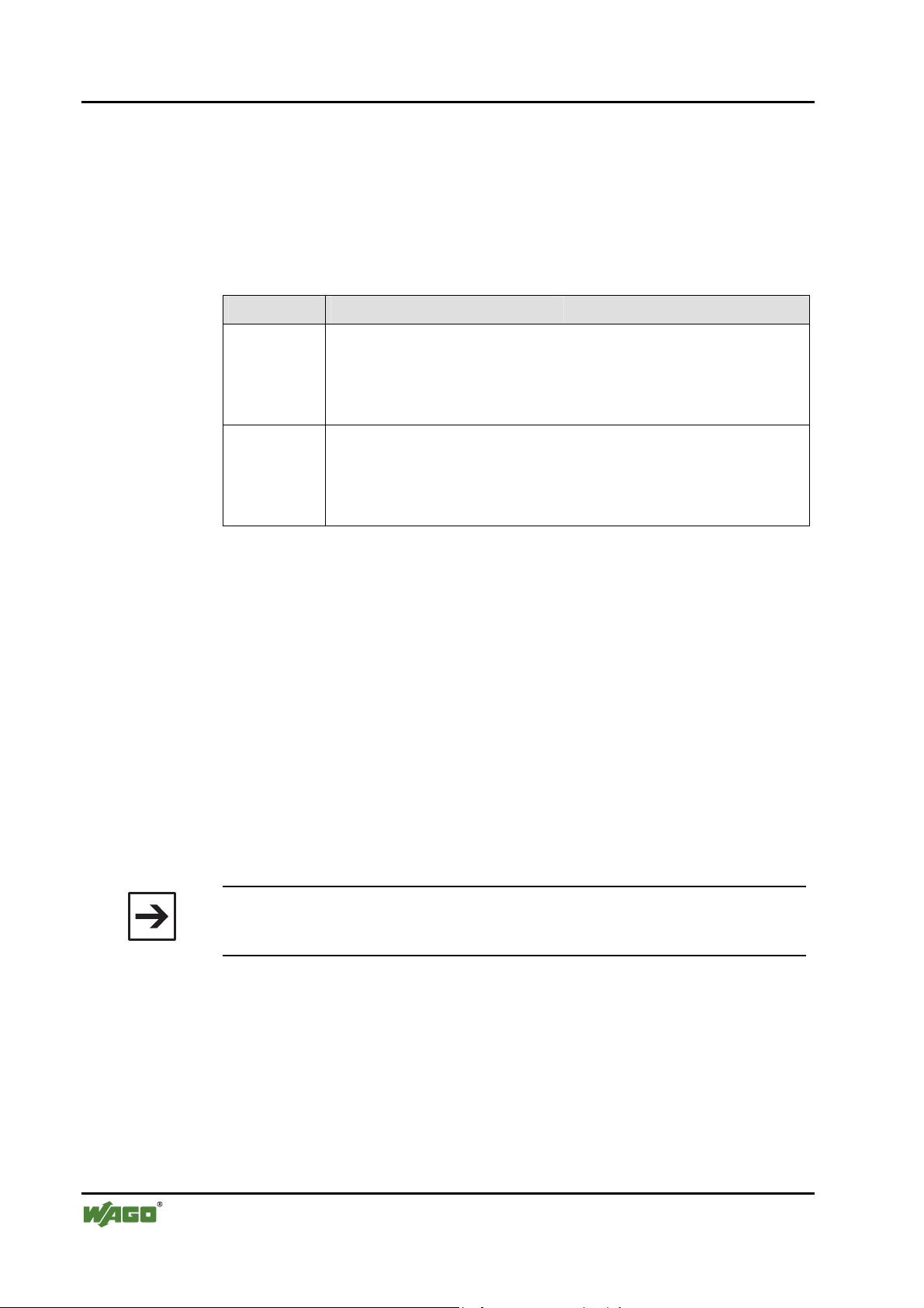
1.2 Symbols
Danger
Always abide by this information to protect persons from injury.
Warning
Always abide by this information to prevent damage to the device.
Attention
Marginal conditions must always be observed to ensure smooth operation.
ESD (Electrostatic Discharge)
Warning of damage to the components by electrostatic discharge. Observe
precautionary measures for handling components at risk.
Note
Routines or advice for efficient use of the device and software optimization.
Additional Information
References for additional literature, manuals, data sheets and web pages.
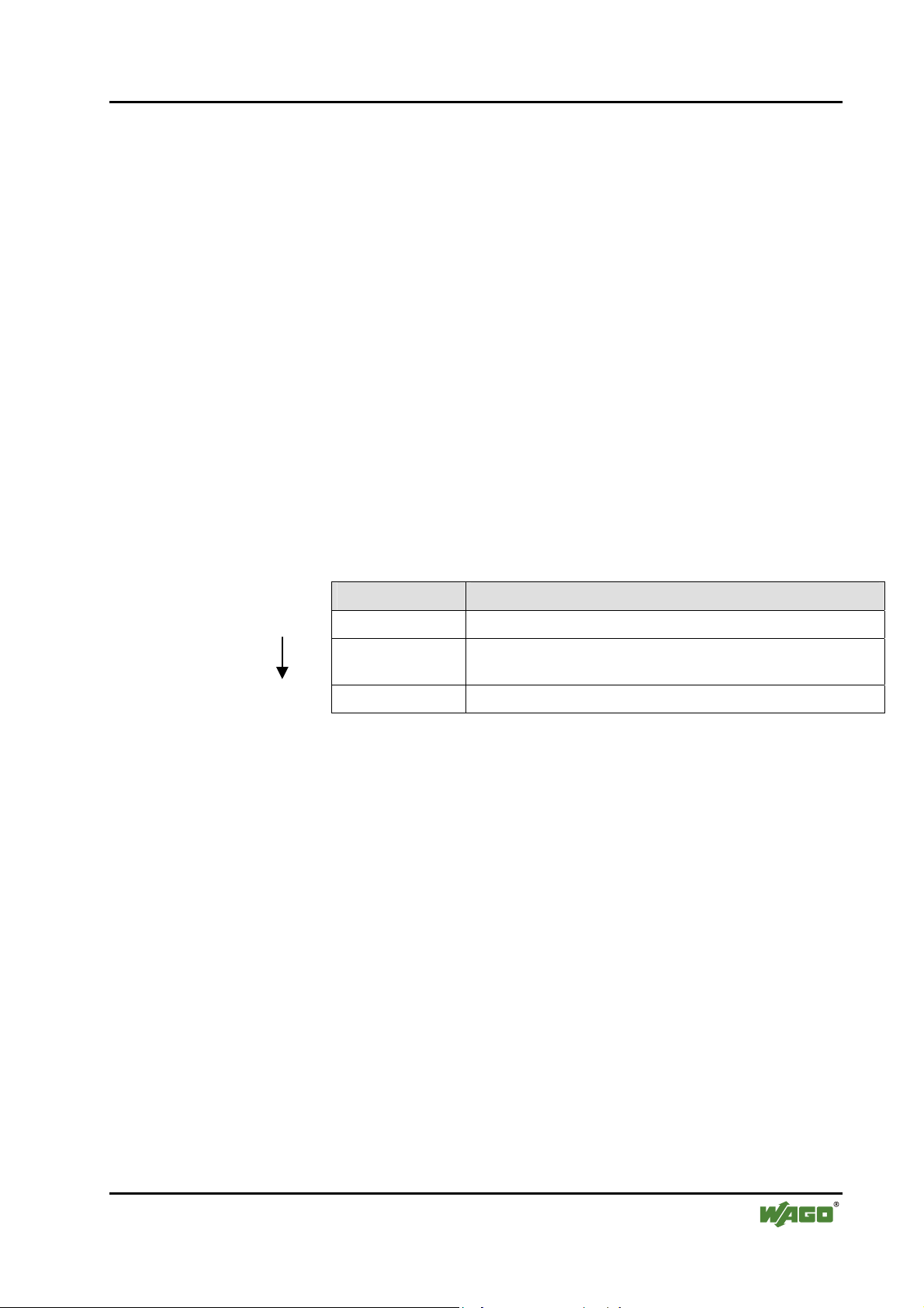
1.3 Number Notation
Number Code Example Note
Decimal 100 normal notation
Hexadecimal 0x64 C notation
Binary '100'
'0110.0100'
within inverted commas,
nibble separated with dots
WAGO-I/O-SYSTEM 750
I/O Modules
Page 9
Important Comments • 9
Safety Notes
1.4 Safety Notes
Warning
Switch-off the system prior to working on bus modules!
In the event of deformed contacts, the module in question is to be replaced, as
its functionality can no longer be ensured on a long-term basis.
The components are not resistant against materials having seeping and insulating properties. Members of this group include: aerosols, silicones, triglycerides (found in some hand creams).
If it cannot determined that these materials appear in the component environment, then additional measures must be taken:
- install of the components in an appropriate enclosure
- handle components only with clean tools and materials.
Attention
Soiled contacts may only be cleaned with ethyl alcohol and leather cloths.
This helps ensure compliance with ESD information.
1.5 Scope
Do not use any contact spray. The spray may impair the functioning of the
contact area.
The WAGO-I/O-SYSTEM 750 and its components are an open system. As
such, the system and its components must be installed in appropriate housings, cabinets, enclosures or in electrical operation rooms. Access must only
be provided via key or tool to authorized, qualified personnel.
The relevant valid and applicable standards and guidelines concerning the
installation of switch boxes are to be observed.
ESD (Electrostatic Discharge)
The modules are equipped with electronic components that may be destroyed
by electrostatic discharge. When handling the modules, ensure that the environment (persons, workplace and packing) is well grounded. Avoid touching
conductive components; e.g., gold contacts.
This manual describes the Bluetooth® RF Transceiver 750-644 from the
WAGO-I/O-SYSTEM 750. Handling, assembly and startup are described in
the manual for the fieldbus coupler/controller. This documentation is therefore
only valid in connection with the appropriate manuals.
WAGO-I/O-SYSTEM 750
I/O Modules
Page 10
10 • I/O Modules
Special Modules
2 I/O Modules
2.1 Special Modules
2.1.1 750-644 [Bluetooth® RF Transceiver]
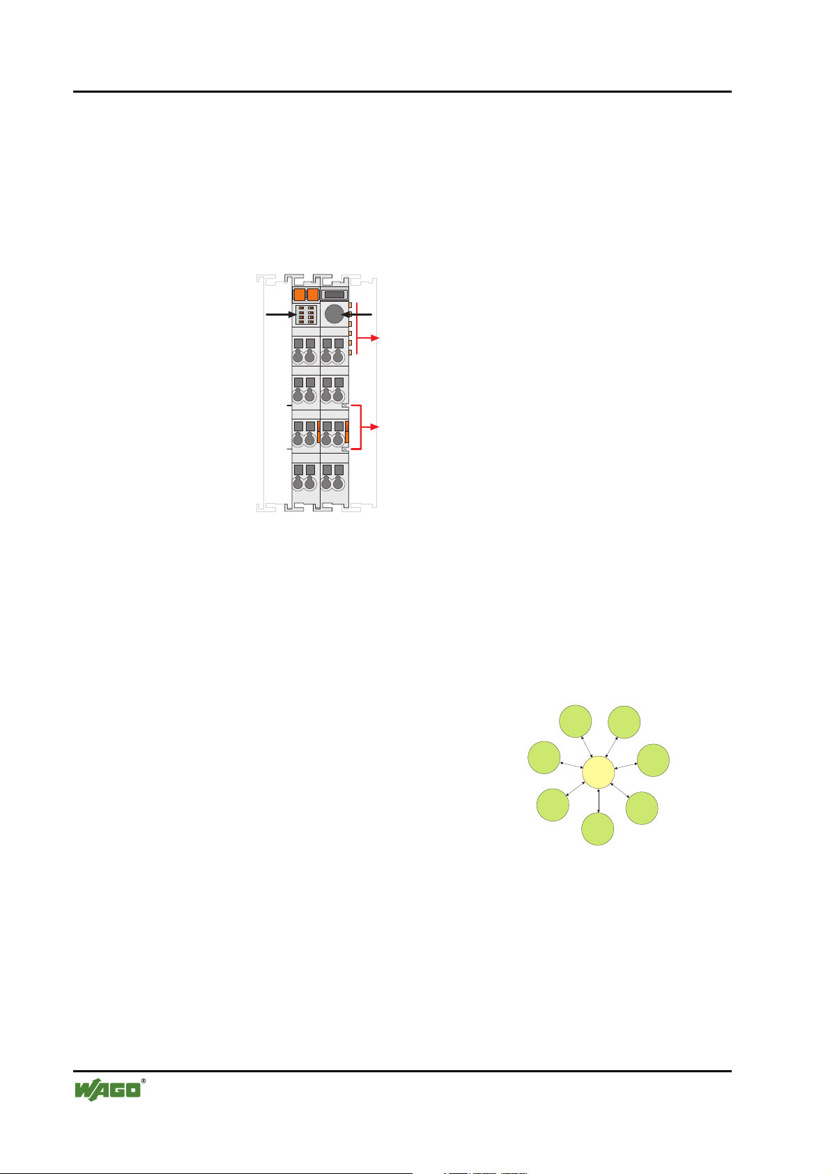
2.1.1.1 View
13 14
Operational and
connection
status
Antenna socket
SMA
Data contacts
Power jumper
contacts
Figure 1: View g064400e
2.1.1.2 Description
The Bluetooth® RF Transceiver 750-644 (referred to in the following as "Bluetooth® module") integrates a Bluetooth® network (piconet) into the WAGO-
I/O-SYSTEM 750. This means that Bluetooth® modules will be installed and
used jointly with the WAGO-I/O-SYSTEM 750 modules in different fieldbus
systems.
The Bluetooth® module facilitates wireless
data exchange within the Bluetooth
It can function as the coordinator (referred to
in the following as the "master") or as the
terminal (referred to in the following as the
"slave") depending on the configuration. A
maximum of seven slaves may communicate
with one master (see
The module's configuration (network configuration/process image mapping) is
determined locally via WAGO-I/O-CHECK software.
750-644
Figure 2).
®
piconet.
Slave
7
Slave
Figure
Slave
1
6
Master
Slave
5
Slave
2
Slave
4
Slave
3
2: Piconet g064403x
The current status of the module is displayed by LEDs. While the LEDs associated with the function of "slave" signal the quality of the connection, the
LEDs associated with the "master" function show the connection status to
each individually connected slave.
WAGO-I/O-SYSTEM 750
I/O Modules
Page 11
I/O Modules • 11
Special Modules
The Bluetooth® module is operated in the public domain ISM 2.4 GHz band
and enables wireless data transfer over large distances. If using the WAGO
Antenna 758-912, ranges of up to 1000 meters can be achieved.
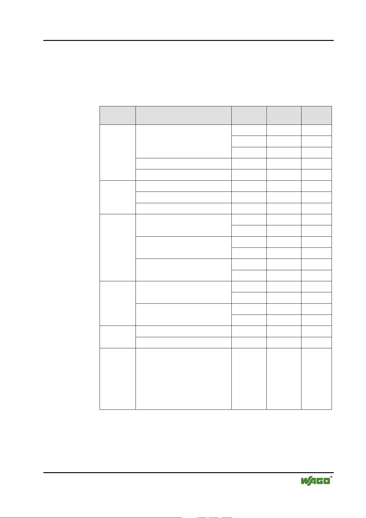
The Bluetooth® module 750-644 can be used with the following couplers/controllers of the WAGO-I/O-SYSTEM 750:
Bus System Coupler/Controller Item No. Hardware
version
PROFIBUS
DeviceNet
CANopen
ETHERNET
Fieldbus coupler
ECO fieldbus coupler 750-343 03 from 06
Programmable fieldbus controllers 750-833 12 from 07
Fieldbus coupler 750-306 11 4I
ECO fieldbus coupler 750-346 02 07
Programmable fieldbus controllers 750-806 02 07
Programmable fieldbus controllers
750-301 01 07
750-303 01 07
750-333 12 from 07
750-337 09 10 Fieldbus coupler
750-338 01 14
750-347 01 04 ECO fieldbus coupler
750-348 01 04
750-837 06 11
750-838 01 11
750-341 03 03 Fieldbus coupler
Software
version
750-342 04 14
Programmable fieldbus controllers
Fieldbus coupler 750-319 07 05 LON
Programmable fieldbus controllers 750-819 08 07
IPC WAGO-IPC 750-870 02 IPC firm-
Other couplers/controllers upon request.
750-841 03 07
750-842 04 12
ware
02.04.
18/0200
Kbus
firmware
01.02.
03(06)
WAGO-I/O-SYSTEM 750
I/O Modules
Page 12

12 • I/O Modules
Special Modules
The version information is contained in the serial number or in the update matrix; both are printed on the right side of the coupler/controller. The serial
number is constructed as follows:
WWYYSWHWFL-Bm1m2m3
Abbreviation
WW Week of manufacture
YY Year of manufacture
SW Software version of the bus coupler
HW Hardware version of the bus coupler
FL Software version of the firmware loader
- Empty space, no additional meaning
B Designation of the soldered bus connector
m1 Manufacturer of the interface card
m2 Manufacturer of the CPU card
m3 Manufacturer of the power supply card
The m3 designation is not included for bus couplers of the ECO family.
Description
The update matrix is constructed as follows:
NO Work Order Number
DS Date Stamp
SW Software version of the bus coupler
HW Hardware version of the bus coupler
FWL Software version of the firmware
loader
WAGO-I/O-SYSTEM 750
I/O Modules
Page 13
I/O Modules • 13
Special Modules
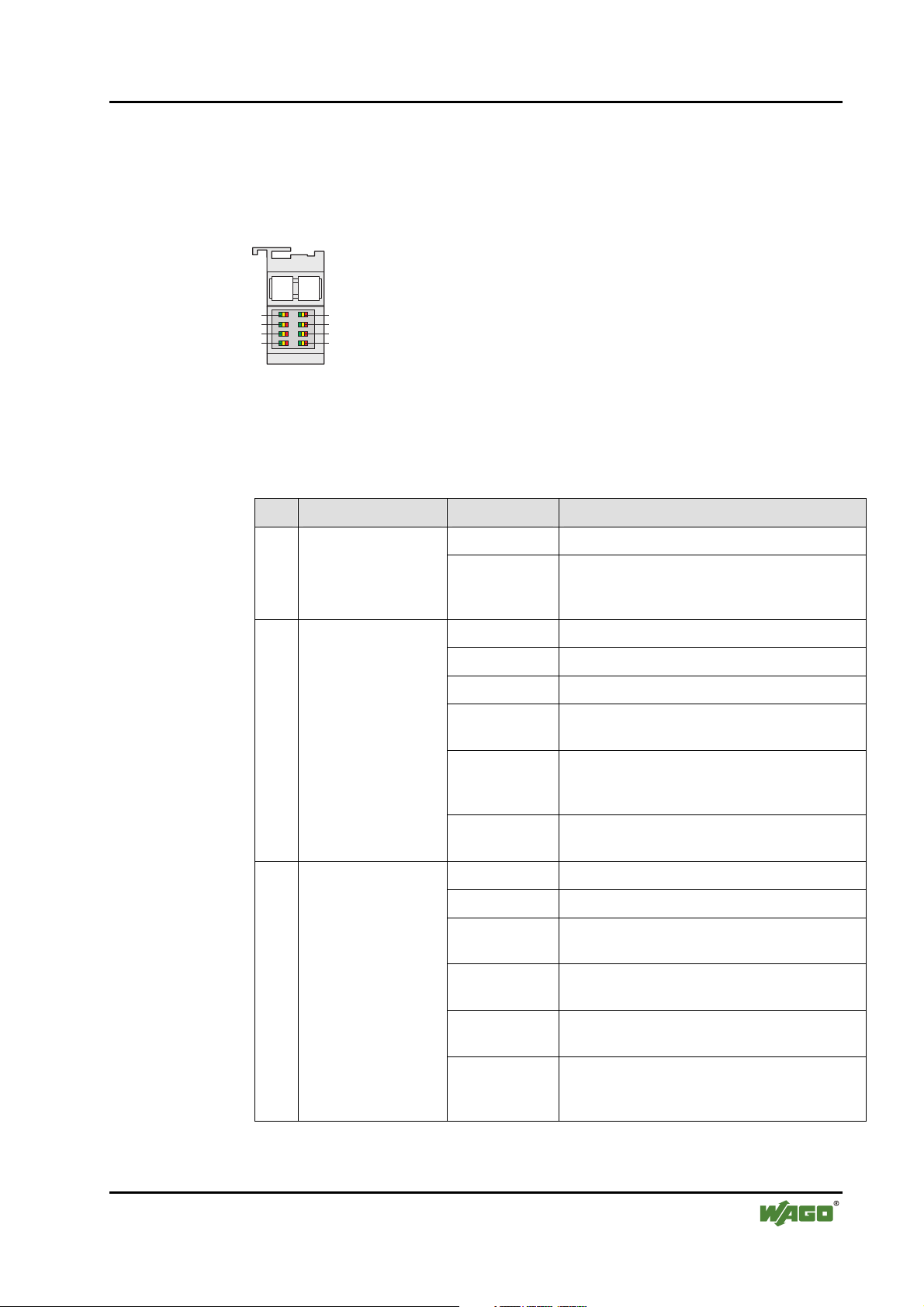
2.1.1.3 Indicators
The LED display must be interpreted differently depending on whether the
Bluetooth® module functions as a master or as a slave (see Sections 2.1.1.3.1
and 2.1.1.3.2).
13 14
1
3
5
7
2
4
6
8
Figure 3: Display Elements g064402x
2.1.1.3.1 Master
Table 1: LED Master Signals
LED Designation Status: Function
Operation status
1
indicator
Connection display of
the first WAGO slot
(communication
2
mode) and signaling
in the configuration
mode
Connection display
for WAGO slots j (j =
3…8
2…7) (in communication mode only)
green Normal operation
red Disruption of the local internal bus connection,
the field voltage or the internal communication
(circuit board)
green Connection to slave(s) established
green flashing Data transfer
off No slave is configured for this slot
yellow flashing Connection to the first slave is being estab-
lished (in communication mode only)
yellow System is configured (in configuration mode
only) or connection to the first slave could not
be established (in communication mode only)
red Connection interrupted by error (in communi-
cation mode only)
green Connection to slave(s) established
green flashing Data transfer
yellow Unsuccessful connection configuration to slot j
(in communication mode only)
yellow flashing Connection to Slot j is being established
(in communication mode only)
red Connection interrupted by error (in communi-
cation mode only)
WAGO-I/O-SYSTEM 750
I/O Modules
off No slave is configured for this slot (in commu-
nication mode only) or the system is in configuration mode.
Page 14

14 • I/O Modules
Special Modules
2.1.1.3.2 Slave
Table 2: LED Slave Signals
LED Designation Status: Function
green Operating status OK (independent of radio
1
Operation status indicator
red Disruption of the local internal data bus
green Connection to master established
green flashing Data transfer
off No master is configured for this slot.
communication)
connection, the field voltage or the internal
communication (circuit board)
2
3, 4
5, 6
Connection display for
connected master
RSSI
Over- or undermodulation of the
Bluetooth
®
receiver
Connection quality
according to bit error
rate
yellow flashing
Connection to the master is being established (in communication mode only)
yellow System is being configured (in configura-
tion mode only) or connection to the master could not be established (in communication mode only)
red Connection interrupted by error (in com-
munication mode only)
green Signal strength of the received signal good
yellow Signal strength of the received signal very
strong (solution: increase distance of the
device)
Red Signal strength of the received signal weak
(solution: reduce distance of the device).
off There is still no information on the signal
strength of the received signal (there is no
connection or there is a connection only
after a few seconds)
green low bit error rate <10-3
yellow bit error rate 10-2 to 10-3
red high bit error rate > 10
-2
(bad transmission line)
off no active connection (similar RSSI)
green > 53 lines free (no or negligible third-party
activity in the frequency range)
activity in the frequency range)
7, 8
Interference display
Number of busy lines
in the 2.4 GHz frequency range
yellow 39…53 free lines
red < 39 marked as free (massive third-party
off no active connection (similar RSSI)
WAGO-I/O-SYSTEM 750
I/O Modules
Page 15
I/O Modules • 15
Special Modules
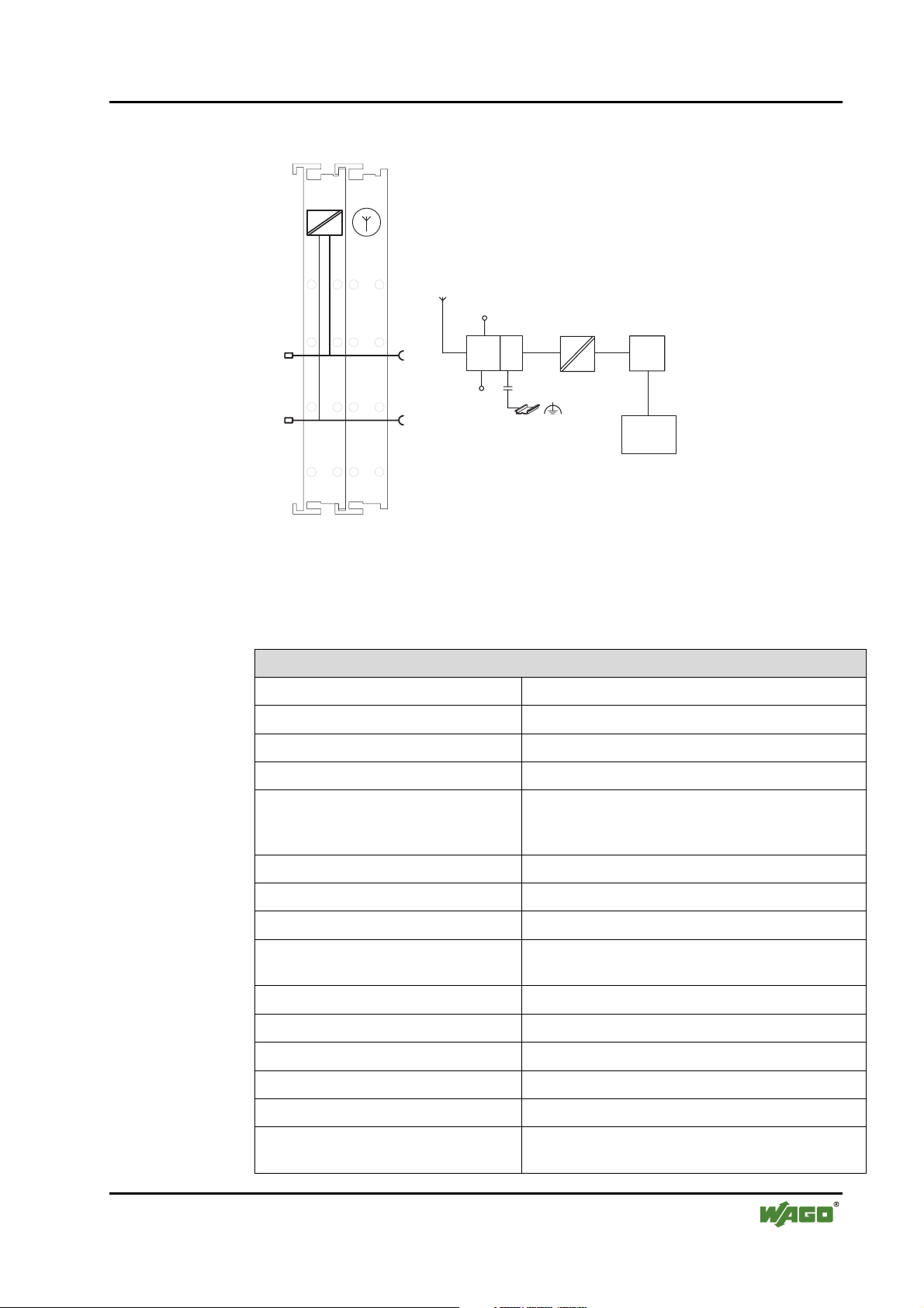
2.1.1.4 Schematic Diagram
Antenna socket
SMA
1
5
1
5
Antenna
24 V
2
6
2
+24 V
0V
3
4
750-644
6
BTModule
7
3
7
8
4
8
0V
OS
SPI
SPI
Logic
8-segment
LED
display
Figure 4: Schematic Diagram g064401e
2.1.1.5 Technical Data
Table 3: Technical Data for Bluetooth® Module 750-644
Module-Specific Data
Radio technology Bluetooth® 2.0 + EDR
Topology Piconet (1 master, maximum of 7 slaves)
Coexistence AFH and adaptive transmitting power
Profiles SPP, PAN
Operating modes Communication mode with ad hoc profile for high
Frequency band public domain, ISM band, 2402…2480 MHz
Transmitting power up to 20 dBm (Bluetooth® Class 1)
Receiver sensitivity -94 dBm
Range (maximum) 1000 m in open air, 100 m in buildings (if using an
Voltage supply (Bluetooth®) through field supply DC 24 V
connectivity and real-time profile for time-critical
applications and configuration mode
external WAGO antenna, item no. 758-912)
Voltage supply (internal) via system voltage DC/DC
Current consumption (Bluetooth®) approx. 8 mA, maximum 35 mA
Current consumption (internal) approx. 20 mA
Isolation 500 V (antenna/system)
Data width, internal Configurable to 12, 24, 48 bytes, including 1 con-
WAGO-I/O-SYSTEM 750
I/O Modules
trol/status byte
Page 16
16 • I/O Modules
Special Modules
Module-Specific Data
Diagnosis (through optical display) Device status, connection status
Diagnosis (through process image) Device status, connection status
[1]
[1]
, time monitoring
Configuration WAGO-I/O-CHECK and WAGO-I/O-PRO CAA
Dimensions (mm) W x H x L 24 x 64
[2]
x 100
Weight approx. 85 g
Accessories
Miniature WSB Quick marking system
External WAGO antenna, SMA, with magnet base (item no. 758-912)
Standards and directives (see Section 2.2 in manual on coupler/controller)
EMC CE Immunity to interference according to EN 61000-6-2 (2005), EN 61131-2 (2003)
EMC CE Emission of interference according to EN 61000-6-3 (2007), EN 61131-2 (2003)
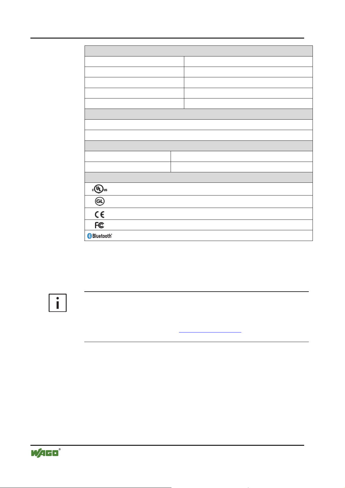
Approvals (see Section 2.2 in manual on coupler/controller)
(UL508) (patent pending)
CULUS
GL (Germanischer Lloyd) (patent pending)
Conformity marking
FCC approval
Bluetooth
[1]
Quality of the radio link, signal strength, interference
[2]
plus approx. 6.5 mm excess length of the SMA socket
[3]
This device complies with Part 15 of the FCC Rules. Operation is subject to the following two conditions: (1) this device may not cause harmful interference, and (2) this device must accept any interference received, including interference that may cause undesired operation.
[3]
®
approval
Additional Information
Please refer to the "Overview on WAGO-I/O-SYSTEM 750 approvals" documentation for detailed information on approvals.
You will find this on the CD ROM "AUTOMATION Tools and Docs"
(item no. 0888-0412) or online at http://www.wago.com under documentation
! WAGO-I/O-SYSTEM 750 ! System Description
WAGO-I/O-SYSTEM 750
I/O Modules
Page 17

I/O Modules • 17
Special Modules
2.1.1.6 Function Description
Bluetooth® technology defines piconet as a topology consisting of a master
and up to seven slaves. Data can be exchanged between each slave and the
master wirelessly and bidirectionally. Data transfer from slave to slave is possible indirectly through the master.
The Bluetooth® module implements Bluetooth® Protocol 2.0+EDR and can be
configured as either master or slave. The configuration and activation of special functions is done through the mailbox interface described in Appendix
6.1. This is used by the startup tool WAGO-I/O-CHECK and function blocks
of WAGO-I/O-PRO CAA in order to provide the user with simple softwaresupported access to the module's full range of functions.
The following networks can be configured with Bluetooth
®
modules:
• Bluetooth® module as master, up to 7 Bluetooth® modules as slaves (real-
time profile). This real-time scenario is distinguished by an especially low
latency and cycle time.
• Bluetooth® module as master and up to 6 active slaves. In this configura-
tion, Bluetooth® modules configured as slaves and other Bluetooth® devices (e.g. Bluetooth® notebooks or PDAs) can be combined (ad hoc profile). This scenario offers flexible connection possibilities and interoperability.
A Bluetooth® module configured as a master can use up to 46 bytes of data
width for bidirectional data exchange with the slaves. In this case, which process data is assigned to which slave can be flexibly configured – the available
data width can be assigned exclusively to one individual slave or be distributed with freely configurable portions among several slaves.
®
With Bluetooth
modules, ranges of up to 1000 m can be achieved with intervisibility. Good reception is also possible inside buildings, even with the distribution of network participants in different rooms or floors of the building.
For maximum security, data exchange can be encrypted. Another security feature of the network is that a piconet configured with Bluetooth® modules allows no penetration by non-authorized devices.
Radio transmission with Bluetooth
outside influences. Thanks to frequency hopping procedures and adaptive
transmitting power, co-existence with other ISM radio technologies (e.g.
WLAN according to IEEE 802.11) is problem-free.
Potential-disturbing influences can be recognized early by the Bluetooth®
module – even before they have a negative effect on communication. Cyclic
and acyclic retrievable diagnostic information that provide information on the
quality of the wireless connection and fulfillment of real-time conditions (in
WAGO-I/O-SYSTEM 750
I/O Modules
®
is robust, particularly when faced with
Page 18

18 • I/O Modules
Special Modules
the real-time profile) are offered for this purpose. The most important diagnostic information is also displayed on the device via LEDs, so that the status can
also be directly monitored without additional components at the installation
site.
Additional Information
The Bluetooth® module starts either with the startup tool WAGO-I/OCHECK or function blocks of the WAGO-I/O-PRO CAA. The function
blocks for configuration are contained in the library
WAGO_Bluetooth_xx.lib, which you can download from the website
http://www.wago.com under Documentation ! WAGO Software 759 !
WAGO-I/O-PRO ! 759-333 ! Additional Information ! Libraries.
WAGO-I/O-SYSTEM 750
I/O Modules
Page 19
I/O Modules • 19
Special Modules
2.1.1.6.1 Bluetooth® Class of Device (CoD)
The Class-of-Device (CoD) is a 24-bit field specifying the capabilities of a
Bluetooth® device that is sent with the packet "Frequency Hop Synchroniza-
tion" (FHS) during the device search. According to the Bluetooth® Standard,
the CoD describes the capabilities of the device, thus supporting the search for
devices with certain functionalities.
The CoD enables a rapid assignment of remote devices to different device
categories such as network, audio, telephony. It is divided into the Major Service Class (bit 23…13), Major Device Class (bit 12…8) and Minor Device
Class (bit 7…2).
Internal device (sub)classes have been specified for the WAGO module. The
device class for the WAGO-I/O-SYSTEM 750 is represented by bit values 1,
1, 1, in bits 7, 6, 5. It is represented by the bit string 110 for bits 4, 3, 2 (see
Table 4).
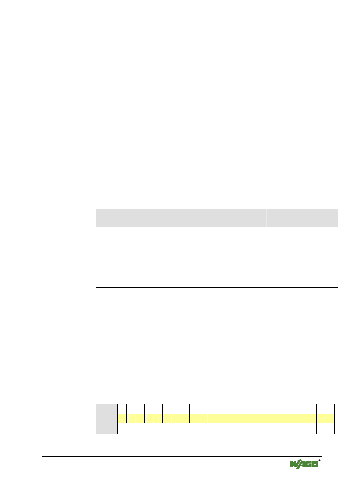
Table 4: Configuration of the CoD
Bit
position
23-16
15, 14 Reserved 00
13
12…8
7…2
1, 0 Reserved, format type 00
Description Suggested values
Major Service Class
Not given, in accordance with the Bluetooth
since there is no service that can be uniquely assigned
Limited Discoverable Mode
According to the Bluetooth
also support the non-discoverable mode
Major Device Class
According to the BT specification, set as "Miscellaneous"
Minor Device Class (can be used WAGO-specific) According to the Bluetooth
Device Class is "Miscellaneous"
WAGO-specific use: use of a bit pattern with the following
two-part device class; e.g., to identify the WAGO-I/OSYSTEM device subclass; e.g., to identify different products in the device class
®
specification, the device must
®
specification: open since the
®
specification,
00000000
1
00000
111
(= WAGO-I/O-System
750)
bit 7,6,5 device class
110
(= bus module 750-644)
bit 4,3,2 device subclass
The complete CoD for the bus module 750-644 is 0x0020F8
000000000010000011111000
Bit
WAGODevice
Class
WAGO-I/O-SYSTEM 750
I/O Modules
or
hex
(see following diagram).
bin
23 22 21 20 19 18 17 16 15 14 13 12 11 10 9 8 7 6 5 4 3 2 1 0
0 0 0 0 0 0 0 0 0 0 1 0 0 0 0 0 1 1 1 1 1 0 0 0
Major Service Class Major Device Class Minor Device Class Type
Page 20

20 • I/O Modules
Special Modules
Note
The device subclass can be set by mailbox commands (see Appendix 6.3.5.9).
The CoD can only be influenced by the device (sub)class. Changes in the
Major Service Class or Major Device Class are not possible.
When loading the factory settings, the device class is set to value 7 and the
device subclass to value 6. This results in a CoD of 0x0020F8 for the Blue-
tooth® inquiry.
Many stacks handle devices according to their CoD. Therefore, the set device
(sub)class can influence the function (indirectly through the CoD) in external
devices..
WAGO-I/O-SYSTEM 750
I/O Modules
Page 21
I/O Modules • 21
Special Modules
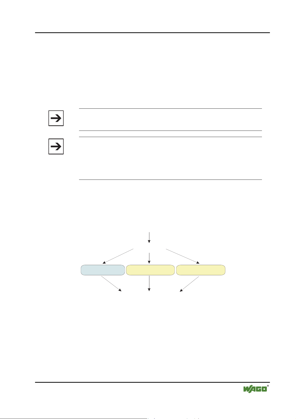
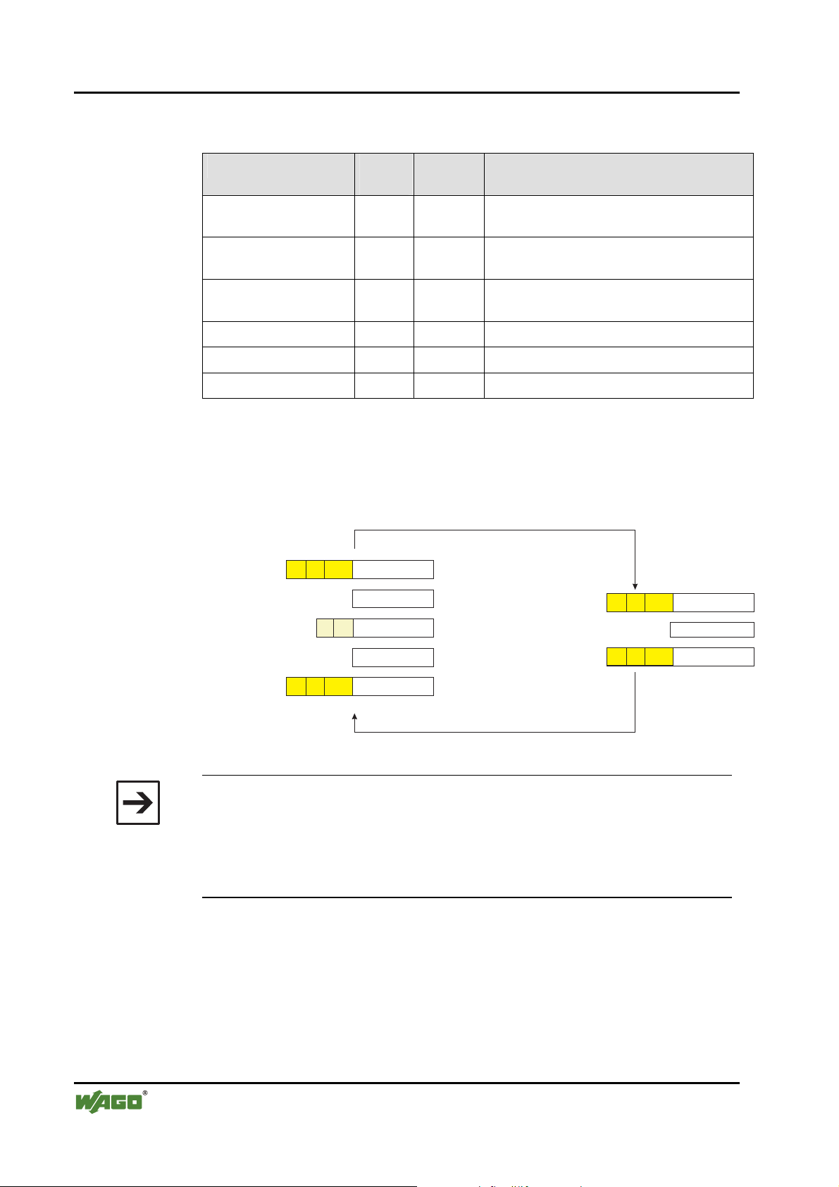
2.1.1.7 Operating Modes
The Bluetooth® module has two different modes available. Each mode fulfills
a certain function:
• Configuration mode
• Communication mode
• in real-time profile
• in ad hoc profile
Note
The Bluetooth® module is in configuration mode when the customer receives it.
Note
If a Bluetooth® master is operated in the real-time profile, up to 7 Bluetooth® slaves can be connected to the master. If the Bluetooth® master is
operated in the ad hoc profile, 6 slaves can be connected. The profile of the
Bluetooth® slaves is irrelevant here. Modes and profiles are a master prop-
erty.
The operating mode is changed (see Figure 5) using WAGO-I/O-CHECK or
function blocks in the WAGO-I/O-PRO CAA and is controlled by mailbox
commands. After the operating mode is changed, the Bluetooth® subsystem is
automatically reset.
Restart
Saved Operation Mode
Configuration Mode
After changing the saved operation mode via mailbox command,
a restart will be performed automatically.
Figure 5: Operating modes g064404e
Communication Mode
Ad-Hoc Profile
Communication Mode
Real-Time Profile
WAGO-I/O-SYSTEM 750
I/O Modules
Page 22
22 • I/O Modules
Special Modules
2.1.1.7.1 Time Required for Initialization
Waiting times occur during the initialization of the module
(see Table 5):
Table 5: Waiting times during normal operation of the module
Waiting times for Seconds
2-3
[1]
[2]
[3]
Connecting to the first slave ~ 5
Establishment of connection to a ready-to-receive slave 2-3
Successful establishment of connection by the master to another
slave
Unsuccessful attempt to connect to another slave 3-5
Inquiry up to 10.3
[1] if the slave is ready-to-receive at the conclusion of the master's boot process
[2] the master does not achieve a connection to the slave when attempted
[3] shorter in more than 15 found devices
2.1.1.7.2 Configuration and Communication Mode
The Bluetooth® module operates automatically in configuration mode during
the first operation. If the communication mode with the real-time or ad hoc
profile has already been selected via WAGO-I/O-CHECK, the module's mode
will be changed to the respective profile.
During startup of the module, the last configuration is the one loaded. If this is
not correct; e.g., in the case of an invalid memory structure, the configuration
is overwritten with the factory settings.
Note
The factory settings can also be reset using the mailbox command "SetFactorySettings". The individual values for the factory settings can be found in
Table 6.
During initialization, the general error bit 26 is set in the status byte. This
means that no mode has been received and there is no valid process data available. LED 1 lights up red during initialization (duration approx. 5s).
Once initialization is complete, the module takes on the last configured operating mode, and LED 1 changes to green. During first operation (factory setting), the module will be in configuration mode following initialization.
In configuration mode, the settings of the module can be configured according
to the desired function, for example by using WAGO-I/O-CHECK. In this
mode, the module can search for other Bluetooth
®
devices within reception
range and is visible for queries.
WAGO-I/O-SYSTEM 750
I/O Modules
Page 23
I/O Modules • 23
Special Modules
However, no data exchange takes place. As there is no cyclic process data, the
general error bit continues to be set.
With suitable settings, or immediately after initialization (if already set beforehand), the module can change to communication mode.
If the module is started in communication mode, profiles are first loaded and
quality-of-service procedures are prepared. Finally, the connection to preconfigured devices is configured. Display LED 1 lights up green. The display of
the remaining LEDs depends on the configuration and the communication profile that has been set (see Sections 2.1.1.3.1 and 2.1.1.3.2).
Before the master and slaves exchange process data, they are synchronized to
a common process data size. This is then used from then on for data exchange.
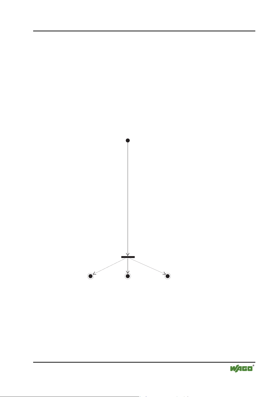
Bootl Loader
Load Operation Mode
Perform Bluetooth module's initialization
Load non-volatile configuration
If configuration is invalid, then load factory settings
Compare non-volatile configuration with factory settings
Correct settings
Initialize Bluetooth stack
Set AccessibleMode ("Not connected") to "Not accessible"
Set Class-of-Device
Set LED (LED 0 green, LED 1-7 off)
Prepare connection establishment
Initialize mailbox
Save process image into module
Set general error bit 2 in status byte to 1
6
Configuration Mode
Figure 6: Initialization of the configuration and communication mode g064405e
WAGO-I/O-SYSTEM 750
I/O Modules
Communication Mode
Real-Time Profile
Communication Mode
Ad-Hoc Profile
Page 24

24 • I/O Modules
Special Modules
2.1.1.7.2.1 Configuration Mode
Mailbox commands are used in configuration mode to configure the Bluetooth® module for use. The commands are passed to the Bluetooth® module
and carried out, for example, with WAGO-I/O-CHECK or by using function
blocks of the WAGO-I/O-PRO CAA.
Additional Information
The mailbox commands for configuring the Bluetooth® module can be found
in Appendix 6.1. In Section 3 and Appendix 6.5, the configuration is described using WAGO-I/O-CHECK. The Bluetooth®-specific function blocks
of the WAGO-I/O-PRO CAA for configuring the module are contained in the
document "WAGO_Bluetooth_03.lib", is available online at
http://www.wago.com under Documentation ! WAGO Software 759 !
WAGO-I/O-PRO ! 759-333 ! Additional Information ! Libraries.
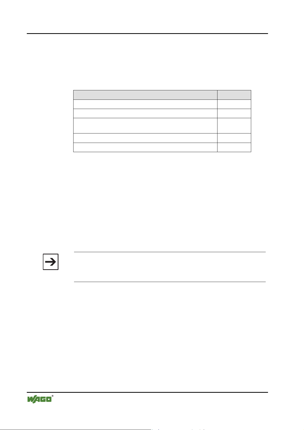
Table 6 below contains the factory settings. These can be restored and saved
in case of altered configuration by using the mailbox commands "SetFactorySettings" (except for Bluetooth
®
device name). A device name is overwritten
by the assigned mailbox command.
Table 6: Factory settings for the Bluetooth® module
Parameter Setting
Bluetooth® device name WAGO-750-644
IP 192.168.0.2
Subnet Mask 255.255.255.0
Gateway 192.168.0.1
Device role slave
Operating mode configuration mode
Mailbox cascade
Encryption active
Authentication with password
Standard password 0000
Quality of Service (QoS) disabled
Class of Device 0x0020F8
Time for reconfiguration of connection 30 seconds
Authorized devices none (all lists are initialized with "0")
Linked devices none (all lists are initialized with "0")
Process image sizes of the up to 7 slaves in the
master
10,0,0,0,0,0,0 bytes (used when changing
the device role to "master")
WAGO-I/O-SYSTEM 750
I/O Modules
Page 25
I/O Modules • 25
Special Modules
2.1.1.7.2.2 Block Transfer
The module parameters can be individually read and written using mailbox
commands (see Appendix 6.1). It is also possible, as an alternative, to upload
or download the complete configuration in 512-byte blocks. For example, a
created or read out configuration block can be used to set up and configure all
additional slaves.
512-byte blocks are sent. The transfer is opened each time by the group
DLD_START described in Appendix 6.3.2.1 and closed with DLD_END.
With each DLD_CONT command, one element of the block is transferred. After transferring one 512-byte block, the module verifies the checksum.
After the copying process has been successfully completed, the module confirms the DLD_END command by sending the calculated checksum and the
return 0x00 (OK).
The format of the configuration block transferred by means of the DLD commands is described in 6.4.
Table 7: Block transfer process using DLD commands
DLD commands Explanations
Procedure
DLD_START Configuration of the block transfer
n x DLD_CONT Transfer of the 512-byte blocks in n* consecutive elements
(* depends on the mailbox size, see Appendix
DLD_END End of the block transfer, testing of the checksum
The exact mode of operation of the commands "DLD_START",
"DLD_CONT" and "DLD_END" can be found in Appendix 6.3.2.
2.1.1.7.2.3 Communication Mode – Real-Time Profile
In the real-time profile, signals can be monitored in real-time. The cycle and
error message time is assured making this profile especially suited for timecritical applications such as system monitoring. In case of an error, the system
can be stopped immediately. The real-time network is invisible to Bluetooth
networks. Real-time capable masters only exchange data with directly connected slaves.
6.3.2.2)
®
Within the module, time intervals between different, repeating events are
monitored by Watchdog and other monitoring mechanisms. In case of disturbances, warnings/errors are signaled, depending on the type of disturbance, or
the module is automatically restarted.
WAGO-I/O-SYSTEM 750
I/O Modules
Page 26
26 • I/O Modules
Special Modules
If there is an existing connection between WAGO devices, the time between
the received packets is measured. If there is a significant timeout, warnings or
error messages are sent (see Table 8). The typical time response is significantly more high performance than the upper limits given here for warnings
and errors.
Table 8: Time responses for Bluetooth® module
Name Value
BTCOM_
WARNTIME
BTCOM_
ERRORTIME
master, 1 slave linked:
master, 2…5 slaves linked:
master, 6 slaves linked:
master, 7 slaves linked:
slave:
master, 1 slave linked:
master, 2…5 slaves linked:
master, 6 slaves linked:
master, 7 slaves linked:
slave:
40 ms
20 ms * (number of end devices + 1)
240 ms
280 ms
280 ms
80 ms
40 ms * (number of end devices + 1)
480 ms
560 ms
560 ms
If the time limits cannot be adhered to, warnings or error messages are issued
via acyclic diagnosis functions (LED displays, see Section 2.1.1.3) or cyclically through the status byte of the process image (see Section 2.1.1.8.1.1).
For optimal time response, a valid piconet configuration must exist. If the
master cannot establish a connection to all slaves, the attempt to reintegrate
these devices leads to interruptions in data communication (see also "SetReconnectionTimePeriod", Appendix 6.3.5.34). To prevent this, you can temporarily remove defective devices from the piconet. No change in configuration
is required for removing the devices; simply set the affected devices to "not
linked" in the "real-time" communication profile. The master then no longer
integrates these devices during this time.
With the next change in operating mode or restart, the master will again try to
connect to all devices.
Note
Only connections to WAGO devices can be configured in the real-time profile.
WAGO-I/O-SYSTEM 750
I/O Modules
Page 27
I/O Modules • 27
Special Modules
2.1.1.7.2.4 Communication Mode – Ad Hoc Profile
"Ad hoc communication" is the "spontaneous" connection of devices. The
main feature is the problem-free connection of very different types of devices.
Therefore, the requirements for partner devices are less strict, making realtime communication impossible when using this profile.
Note
In the ad hoc profile, you can connect up to 6 slaves with one master (up to 7
slaves in the real-time profile).
Note
Adherence to time limits (see Section 2.1.1.7.2.3) is not monitored in the ad
hoc profile, making this profile ideal for less time-critical applications.
WAGO devices can be connected with each other and with third-party Blue-
tooth® devices in the ad hoc profile. The Bluetooth® protocols SPP & PAN are
available for this purpose (see Table 14).
2.1.1.7.2.4.1 Connecting WAGO Devices with External Devices
The Bluetooth® module from WAGO can be connected with other WAGO
Bluetooth® modules via L2CAP. These connections are especially fast and are
subject to various reliability and reaction speed requirements. Slaves that support this form of connection are referred to as WAGO devices in this document.
By using PAN and SPP, devices that do not fulfill these requirements can also
be used. These devices, which actually control the exchange of the process
image, but not the real-time requirements, are called "external devices".
When configuring the wireless connection of an external Bluetooth® device
(e.g., PDA) to a WAGO Bluetooth® device, note that external devices must
have a valid protocol header embedded in their Bluetooth® packets. This must
be configured according to the following pattern (see Table 9):
WAGO-I/O-SYSTEM 750
I/O Modules
Page 28
28 • I/O Modules
Special Modules
Table 9: Configuration of the Bluetooth® Packet
Channel name Length
Value Description
in bytes
CHANNEL_SELECT 1 0000 0001
Virtual channel selection, always 0x01
(0x01)
STATUS_FLAGS 1 0000 0000
Status bits, always 0x00 for external devices
(0x00)
STATUS_DATA_SIZE 1 xxxx xxxx Data length in bytes, according to "cutoff"
(see Section
2.1.1.8.1.2)
DATA[1] 1 xxxx xxxx 1st byte of process data
... ... xxxx xxxx ...
DATA[n] (=cutoff) 1 xxxx xxxx nth (last) byte of process data
This header is automatically added in WAGO (see Figure 7).
WAGO Device
Header is added and removed automatically
Header is added
automatically
Control/status byte
are not transmitted
Local data
Control/status byte
are added
Header is removed
automatically
Bluetooth
®
Cutoff
01 00 Data
length
C/S int Data
Cutoff
01 00 Data
length
Data
Data
External Device
Header must be added and removed from the device
Radio transmission
Header is removed
from the device
Local data
Header must be
created from the device
Bluetooth
01 00 Data
01 00 Data
®
Cutoff
length
Cutoff
length
Data
Radio transmission
Figure 7: Adding the header in data packets of external devices g064406e
Note
Missing data in the protocol header may lead to termination of the connection. Therefore, prepend the 3-byte channel information (0x01 and 0x00 and
field length) to the data to be transferred if you would like to send from an
external device to a WAGO device.
WAGO devices add the header automatically.
WAGO-I/O-SYSTEM 750
I/O Modules
Page 29

I/O Modules • 29
Special Modules
2.1.1.7.2.5 Configuration of the Wireless Connection
End devices are passive during configuration of the connection. Masters are
also passive if the connection is configured through SPP or PAN by external
devices. During the configuration of a connection, the status of a remote node
(if it is authorized and entered on the external devices list) is tested. Connections are actively configured only if the Bluetooth® module is operating as a
master in the real-time or ad hoc profile. The module can be connected
through the PAN profile using port 3501.
2.1.1.7.2.6 Net Forming
"Net forming" is the configuration of Bluetooth® modules for the purpose of
defining a Bluetooth® network.
The role of the Bluetooth® module - master or slave - is established in the configuration mode (see Section 2.1.1.7.2.1). The devices that are to be included
in the list of permitted devices is also established by entering the respective
device MAD IDs in WAGO-I/O-CHECK. A search can serve as an additional
aid here. Then, out of all the entered MAD IDs, those devices to which a connection is actually to be configured are marked as "linked". The prerequisite
for a successful configuration is a bilateral authorization, both from the master
for the slaves and from each slave for the master. Then the new settings are
downloaded into the module.
If you select "real-time" or "ad hoc" in the communication profile (see Section
2.1.1.7.2.3 to 2.1.1.7.2.4), a search for already configured Bluetooth® devices
will be performed first. The list of all authorized slaves is processed. The
module attempts to actively connect (master) with connected devices or to accept connections from them (slave). If a device is not marked as "linked" in
the list, connection attempts are refused by the device (slave) or no attempt to
connect to this device is made (master). Even if one or more devices are not
connected, data exchange with the remaining participants begins immediately
after the connection attempt.
The module attempts to configure the complete network at regular intervals.
Devices that cannot be reached temporarily are also reconnected as soon as the
connection is re-established. It is irrelevant whether a connection has never
been configured or whether it failed due to power failure at the site of the remote node, for example (can be set using "SetReconnectionTimePeriod").
WAGO-I/O-SYSTEM 750
I/O Modules
Page 30

30 • I/O Modules
Special Modules
Note
Wireless packets are only accepted and forwarded to the slave if a bilaterally
authorized wireless connection exists; i.e., the Bluetooth® MAC address of
the communication partner is entered in the table of permitted devices and the
table entry has been activated for the creation of a connection (linked) in the
master and slave. Since a maximum of seven remote devices can be linked,
the entry of authorized MAC addresses is independent of the process of linking/delinking.
WAGO-I/O-SYSTEM 750
I/O Modules
Page 31

I/O Modules • 31
Special Modules
2.1.1.8 Process Image
Process data communication using the Bluetooth® protocol is cyclic. Data is
requested, processed in a fixed sequence and exchanged between master and
slaves.
For configuration, diagnosis and register communication, data is transmitted
acyclically between modules and locally connected applications - but not
wirelessly (see Figure 8).
Both the cyclic and acyclic communication share a transmission channel - the
process image.
Fieldbus
WAGO-I/O-CHECK
WAGO-I/O- CAAPRO
Configuration,
Diagnostics
(acyclic)
Figure 8: Cyclic and acyclic communication g064407e
Bluetooth
Module
Process image
Process data exchange
®
Radio Channel
(cyclic)
Bluetooth
Module
®
Configuration,
Diagnostics
(acyclic)
Process image
Fieldbus
WAGO-I/O-CHECK
WAGO-I/O- CAAPRO
The size of the process image for the Bluetooth® module can be set as a fixed
size, 12, 24 or 48 bytes. The process image contains 2 bytes of control information consisting of a control / status byte and an internally used byte.
The mailbox is superimposed in a size of 6, 12 or 18 bytes on the Bluetooth
process data as long as the control bit (0x20) is set.
Mailbox and process image sizes are set either via startup tool WAGO-I/OCHECK or by using WAGO-I/O-PRO CAA over the address 0 in the parameter channel.
Table 10 explains the breakdown of the data in process data and register communication.
WAGO-I/O-SYSTEM 750
I/O Modules
®
Page 32

32 • I/O Modules
Special Modules
Table 10: Process data and register communication
Process data communication
Register Communication
Mailbox switched on Mailbox switched off
Control /status
(1 byte long, from byte 0)
Used internally
(1 byte long, from byte 1)
Mailbox
(Acyclical data,
Control /status
(1 byte long, from byte 0)
Used internally
(1 byte long, from byte 1)
Control /status
(1 byte long, from byte 0)
Used internally
(1 byte long, from byte 1)
Register data
(2 bytes long, from byte 2 to 3)
6…18 bytes long,
from byte 2 to n)
Process data
(Cyclical data,
0…32 bytes long,
Process data
(Cyclical data,
0…32 bytes long,
from byte 2 to m)
Invalid data
(from byte 4 to m)
from byte n + 1 to m)
(Pay attention to the valid-
ity of the data!)
The possible settings with regard to the overall process image and mailbox
size are explained in the following graphic.
Control/status byte
Reserved
Process data length
12 byte
Process data length
24 byte
Process data length
48 byte
Figure 9: Superimposition of the mailbox and register data on the process data g064408e
10
11
12
13
14
15
16
17
18
19
20
21
22
23
24
25
26
27
28
29
30
31
32
33
34
35
36
37
38
39
40
41
42
43
44
45
46
47
0
1
2
3
4
5
6
7
8
9
Process data 12-46 byte Control/status = 0x00
Register data 2 byte Control/status = 0x80
Mailbox
6 byte
= 0x20Control/status
Mailbox
12 byte
= 0x20Control/status
Mailbox
18 byte
= 0x20Control/status
WAGO-I/O-SYSTEM 750
I/O Modules
Page 33

I/O Modules • 33
Special Modules
If the mailbox bit (bit 25 in the control byte) is set to masked mailbox (see
Table 10), the mailbox is masked by the cyclical data field. The masked field
is then no longer valid; however, the non-masked field continues to be updated and may be used. If the mailbox flag is not set, the mailbox is masked
and the cyclical data field is valid. The desired setting is confirmed by mirroring in bit 25 of the status byte.
Note
Consider the validity of the data areas in your application program
(WAGO-I/O-PRO CAA).
To activate register communication (see Table 10), bit 27 in the control byte
is set. Resetting this bit switches the register communication off again. The selected setting is mirrored in bit 27 of the status byte. The register data is covered with an offset and a size of 2 bytes by the respective cyclic or acyclic
(covered by the mailbox) memory area.
Attention
During register communication, the mailbox and process data are invalid!
In the following Sections 2.1.1.8.1 and 2.1.1.8.3, the different types of communication between Bluetooth® modules are described. You can find an overview in Table 11.
Table 11: Overview of types of communication
Type of communication Configuration of the control / status byte
Process data communication
without mailbox
Process data communication
with mailbox
Register Communication
Control byte
Status byte
Control byte
Status byte
Control byte
Status byte
no bit set (0x00)
no bit set (0x00)
(contains additional diagnostic information, see Section
5
Bit 2
set (0x20)
5
and 26 set (0x60)
Bit 2
(contains additional diagnostic information, see Section
7
Bit 2
set (0x80)
7
set (0x80)
Bit 2
(contains additional information, e.g. the
register number, see Section
2.1.1.8.1.1)
2.1.1.8.1.1)
2.1.1.8.3.1)
WAGO-I/O-SYSTEM 750
I/O Modules
Page 34

34 • I/O Modules
Special Modules
2.1.1.8.1 Process Data Communication
During active process data communication, cyclic process data is exchanged
between master and slaves.
2.1.1.8.1.1 Configuration of the Control and Status Bytes
In process data communication, the control byte is configured as follows:
Table 12: Configuration of the control byte
Control byte
Bit
27 2
6
2
5
2
4
2
3
2
2
2
1
2
0
Value/
Description
Bit Value Description
20 0 Reserved (always 0)
21 0 Reserved (always 0)
22 0 Reserved (always 0)
23 0 Reserved (always 0)
24 0 Reserved (always 0)
0 Mailbox masked 25
1 Mailbox unmasked
26 0 Reserved (always 0)
27 0 During process data communication, always 0
0 0 Mailbox 0 0 0 0 0
(switch between process data communication and register communication)
In the status byte, messages, warnings and errors are signaled as follows:
Table 13: Configuration of the status byte
Status byte
Bit
Value/
Description
Bit Value Description
20 0 Reserved (always 0)
0 No warning
21
1
WAGO-I/O-SYSTEM 750
I/O Modules
27 26 2
Gen-
0
eral
error
Warning of obsolete process data. Indicates that no packet has been received
from the other party for a connection within the time defined as the error limit
(for times, see table from 2.1.1.7.2.3)
5
24 2
Mailbox 0
3
2
General.
warning
2
2
Mailbox
(remote)
Monitoring of
time behavior
1
2
0
0
Page 35

I/O Modules • 35
Special Modules
Bit Value Description
22
23
24 0 Reserved (always 0)
25
26
27 0
0 Mailbox of the connected device covered
1 Mailbox of the connected device uncovered (warning of obsolete data)
0 No warning
Warning; e.g., if after the expiration of a defined time limit for warning mes-
1
sages, no packet has been received from the other party
0 Mailbox masked (confirmation of the bus module)
1 Mailbox unmasked (confirmation of the bus module)
0 Wireless connection is established
Warning of non-existence of process data or invalid process data, for example in
1
configuration mode, during a restart or in the case of an interrupted wireless connection
During process data communication, always 0 (confirmation of the bus module)
(switch between process data communication and register communication)
2.1.1.8.1.1.1 Connecting WAGO Devices and External Devices
Slaves are divided into two groups: WAGO devices and external devices. The
WAGO devices use the real-time profile and the connection over L2CAP. External devices can be connected with the master using the ad hoc profile by
SPP profile or through PAN. Both groups are therefore administered in separate tables, even if they must be considered together with regard to simultaneous connections. The table for WAGO devices can accept up to seven entries.
Up to six devices are administered for external devices. A maximum of seven
simultaneous connections can exist at the same time, independently of how
many devices are listed in the tables of authorized devices using their MAC
addresses (see Table 14 and Table 15).
Table 14: Differences between WAGO devices and external devices
Table
Protocols
Profile of the master for a
connection
Maximum number of
slaves/slots per master
Process image
Module bus (in bytes)
Data width of wireless transmission
Initiator of the connection
WAGO-I/O-SYSTEM 750
I/O Modules
WAGO devices External devices
WAGO_DEVICE (0x20) EXTERNAL_DEVICE (0x10)
L2CAP SPP, PAN
Real-time, ad hoc Ad hoc
7 (6 in the ad hoc profile) 6
10, 22, 46
(Process image – 2)
per slot, according to the
"cutoff"
Master Slave
device-specific
per slot, according to the "cutoff"
Page 36

36 • I/O Modules
Special Modules
If WAGO and external devices in different modes are connected with a
WAGO master, the following guidelines apply for communication with each
other (see Table 15):
Table 15: Possible connection of a master with WAGO or external slaves
Slave
Master
Real-time profile
Ad hoc profile
WAGO BT module
Real-time profile
up to 7 devices - -
up to 6 devices up to 6 devices
In the ad hoc profile, a maximum of 7 devices can be active at the
same time, but there are always 13 slots available for configuration.
WAGO BT module
Ad hoc profile
External device
In the master, slots 1 through 7 correspond to the entries in the table of
WAGO devices. In the ad hoc profile, slots 8 through 13 are added with the
table entries for external devices.
In the ad hoc profile, connections to a maximum of seven slaves are established. Of these, a maximum of six can be (see Table 15) WAGO slaves and a
maximum of six can be external devices. By using up the tables for external
and WAGO devices, process image areas can be configured for up to 13 slots
in the master.
Note
When changing to the ad hoc profile, care must be taken that the real-time
device is not connected to slot 7. If a device with a "cutoff" greater than zero
is configured, slot 7 is filled with zeros in the process image.
In the slave, the process image always contains only one slot in which the configured master is unmasked. The width of a slot is determined by the "cutoff"
of this slot.
WAGO-I/O-SYSTEM 750
I/O Modules
Page 37

I/O Modules • 37
Special Modules
2.1.1.8.1.2 Process Image Mapping of the Master
Up to seven slaves can be connected to one master. The process images of
these slaves are mapped in the process image of the master.
The process image consists of a fixed number of virtual plug-ins for the Blue-
tooth® master and slaves, designated as slots. Each slot is assigned a defined
share of the process image by means of the process image mapping. One slave
can be configured for each slot, to which data can be transmitted in the area
assigned to this slot. A maximum of 6 or 7 devices can be active at one time.
The slots can occupy a length of up to 46 bytes in the master (see
Figure 10).
If only one slave is connected to the master, this slave can take advantage of
the entire available size of the master.
In WAGO-I/O-CHECK (configuration mode), the user determines which and
how much data the individual slaves currently occupy in the process image of
the master.
The local process image is constructed similar to that in
Figure 9. For data ex-
change between devices, the available area after byte 2 is further divided.
Figure 10: Mapping of the slaves in the master process image g064409e
Note
The size of the slave process images in the process image of the master can
be changed, not only by WAGO-I/O-CHECK, but also of the command "SetRemoteSize". The operation is symmetrical for the data stream entering or
exiting the master.
After changing to communication mode, the data exchange between master
and slaves begins. The master requests data that the slave sends back over the
Bluetooth
WAGO-I/O-SYSTEM 750
I/O Modules
®
network.
Page 38

38 • I/O Modules
Special Modules
In doing so, the slaves only send "excerpts" of their process data to the master.
The size of these "excerpts" is determined by "cutoff" in the configuration
mode. The command "cutoff" is symmetrical for the data stream entering and
exiting the master. The current data to be read and written, which are assigned
slots in the master's process image, remain (see Figure 11).
Slave A Slave B Slave C
...
...
Slave X
Process image
...
Radio transmission
(without control/status byte )
Data Direction Slave Master
Data Direction Master Slave
Master
Cut off by cutoff, is not transmitted
Figure 11: Process image mapping between master and slaves g064410e
Slot1 Slot 2 Slot 3 Slot 4 Slot 5 Slot 6
The following example (see Table 16) shows that both slots in the process image not occupied by slaves (see slot 1 and 4) as well as slots that are not visible due to a "cutoff" of 0 (see slot 4) can be visible. A "cutoff" of 0 is independent of whether a device has been set up for the slot or not.
Table 16: Example of a slot configuration
Slot Slave Cutoff Offset
...
1 - 4 0
2 "Pump" 6 4
3 "Valve" 10 10
4 - 0 20
WAGO-I/O-SYSTEM 750
I/O Modules
Page 39

I/O Modules • 39
Special Modules
In an additional example, we describe how the slot configurations behave in
conjunction with a configuration of the master (process image size = 48
bytes):
WAGO Table External Table
W1 permitted cutoff = 6 E1 linked cutoff = 6
W2 linked cutoff = 6 E2 linked cutoff = 6
W3 free cutoff = 0 E3 linked cutoff = 6
W4 linked cutoff = 4 E4 free cutoff = 0
W5 linked cutoff = 6 E5 free cutoff = 0
W6 free cutoff = 0 E6 free cutoff = 0
W7 linked cutoff = 6
Resulting process image in the master (ad hoc profile)
• 13 available slots, 5 of these with a width of 0 (W3, W6, E4, E5, E6)
• Since no connection is established with W7, the slot remains filled with ze-
ros
W1 W2 W4 W5 W7 E1 E2 E3
0 48
Resulting process image in the master (real-time profile)
• 7 available slots, 2 of these with a width of 0 (W3, W6)
W1 W2 W4 W5 W7 free
0 48
E1 has been removed in the configuration mode (ad hoc profile)
• "AllowRemoteDevice" with external Table E1 and MAD-ID: 0:0:0:0:0:0
• After removing E1, the slot is filled with zeros. No data are transmitted to
this slot
W1 W2 W4 W5 W7 00000... E2 E3
0 48
WAGO-I/O-SYSTEM 750
I/O Modules
Page 40

40 • I/O Modules
Special Modules
W6 has been processed in the configuration mode (ad hoc profile)
• "AllowRemoteDevice" with MAC address of W6
• "Cutoff" for slot 6 raised from 0 to 6
W1 W2 W4 W5 W6 W7 E2 E3
0 48
Connection to E2 is disconnected (ad hoc profile)
• UnbindRemoteDevice or end device discontinues the connection
• Slot assignments are not changed
• The last data is retained until the next reboot
W1 W2 W4 W5 W7 E1 E2 (Data
obsolete)
0 48
Control/status byte and internally used byte
The complete process image is first transmitted from the slave to the master. If
the slave has received a process image of the master, it sends only those bytes
that are still visible after the "cutoff" from this point on. It is always the visible
portion of the process image only, which is not truncated by "cutoff", that is
transmitted from the master to the slave.
Note
Missing data in the protocol header may lead to termination of the connection. Therefore, prepend the 3-byte channel information (0x01 and 0x00 and
field length) to the data to be transferred if sending from an external device to
a WAGO device. WAGO devices add the header automatically (see Section
2.1.1.7.2.4.1).
E3
WAGO-I/O-SYSTEM 750
I/O Modules
Page 41

I/O Modules • 41
Special Modules
Slave's process image
12, 24, 48 Byte
Usable process data (local)
Control/status byte
Byte used internally
10, 22, 46 Byte
Cutoff
will be transmitted
Master's process image
12, 24, 48 Byte
Slave
Radio transmission
Master
Importing of individual
information (cutoff)
Cutoff size entry
into header
Bluetooth®
protocol header
Bluetooth® protocoll
Bluetooth®
protocol header
Assignment of slave process image
to a slot within the master process image
Control/status byte
Byte used internally
Slot1 Slot 2 Slot 3 Slot 4
Figure 12: Transmission of additional information in the Bluetooth® protocol header g064411e
The "cutoff" can be separately set for each slot with the command "SetRemotePiSize" (see Appendix 6.3.4.1).
To set up specific devices for slots, use the command "AllowRemoteDevice"
(see Appendix 6.3.5.26) together with the MAC address of the target device. If
no device is to be set up for the slot, use instead of a valid MAC address the
address 0:0:0:0:0:0. Only those slots in which valid MAC addresses are entered can be activated (linked) (see Appendix 6.3.5.28, BindRemoteDevice).
The configuration of the display of a slot in the process image by "cutoff" is
completely independent of this.
The number of bytes before the start of a slot is called its offset. The offset of
a slot in the process image of the master may vary depending on the configuration. The offset for any slot can be calculated with the following formula:
The two additional allowed bytes are the control/status byte and the internally
used byte. All commands that change the slot width or the assignment of devices to slots can only be used in the configuration mode. The position of the
data of a remote device in the local process image is therefore unchanged in
communication mode.
WAGO-I/O-SYSTEM 750
I/O Modules
Page 42

42 • I/O Modules
Special Modules
Note
The offset begins with the 3rd byte of the process image (after the control/status and internal bytes).
2.1.1.8.1.3 Process Data Mapping of the Slaves
The process image of the master occupies only one slot (the first) in the process image of the slave. This first slot uses the entire process image size. In this
case, it does not matter which cutoff size was set for slot 1 in the slave. The
configuration of the cutoff is only valid in the master and is not utilized in the
role as slave. Only those bytes that lie within the cutoff allowed by the master
for the slave are updated in this slot, however.
Master's process image
12, 24, 48 Byte
Slots to be transmitted
Master
Control/status byte
Byte internally used
Slot1 Slot 2 Slot 3
Bluetooth®
protocol header
Radio transmission
Slaves
Slave A Slave B Slave C
Process data, updated via Bluetooth®
Unassigned areas of the process image
Bluetooth® protocol
Slot 1 Slot 1Slot 1
Master cutoff
process image of Slave B
12, 24, 48 Byte
Figure 13: Process image mapping of the slave g064413e
WAGO-I/O-SYSTEM 750
I/O Modules
Page 43

I/O Modules • 43
Special Modules
2.1.1.8.1.4 Up-to-Dateness of the Process Image
WAGO master and WAGO slave regularly send their current process image
independently of changes. If one party, (master or slave) no longer receives a
new process image, the most recently received data remains current. If the
master receives no new process image from a WAGO slave over a longer period of time, it signals this in its status byte (in the real-time profile, see Section 2.1.1.8.1.1).
The master also sends a current process image to external devices; however,
the updating of received data is not tested. There is no signaling in the status
byte as with WAGO devices. The recency of the data from external devices is
therefore not certain.
2.1.1.8.1.5 Aging Due to break off of Connection
If a connection ends, regardless of whether intended (by the command "UnbindRemoteDevice", see Appendix 6.3.5.29) or by the failure of the remote
device, the slot configured for this device is retained. The last transmitted data
remain in this slot until the connection is re-established.
In WAGO devices, the failure of a connection is signaled by LEDs and the
status byte. In the case of an intended cutoff of the connection, obsolete data is
not signaled as an error. When the connection is re-established, the parts of the
process image configured for this slot are overwritten with current data regardless of the previous status.
WAGO-I/O-SYSTEM 750
I/O Modules
Page 44

44 • I/O Modules
Special Modules
2.1.1.8.2 Mailbox Communication
Modules with mailbox functionality have an acyclic communication channel
(mailbox) in the process image. The data exchange between module and application can be significantly expanded over this channel without enlarging the
process image. The mailbox masks cyclic data in the process image if active.
Depending on the module function, the remaining cyclic data is valid and
available during mailbox communication (see page 32, Figure 9).
All relevant functions and configuration steps for communication with other
®
Bluetooth
devices are mapped by mailbox commands. This make knowledge
of the most important mailbox commands vital for the manual configuration of
the module through the process image. To configure the module using
WAGO-I/O-CHECK, however, this knowledge is not necessary; all module
functions are accessible via graphical interface.
Note
Please pay attention to the instructions for the use of modules with mailbox
functionality in the respective handbook for your coupler/controller.
2.1.1.8.2.1 Aging of Data by the Mailbox
If the mailbox is activated, it covers a part of the process data. Thus, select
data is covered in the input process image(see Figure 14). Data not covered is
not updated either if at least 1 byte of the respective slot of the mailbox is covered. After the mailbox is deactivated, the current data from the last received
process image is immediately displayed.
Without Mailbox
Cutoff size
Received process image
Slot is updated
Control/status byte
Byte internally used
Slot 1 Slot 2 Slot 3 Slot 4
Process images of the remote devices
Input process image
WAGO-I/O-SYSTEM 750
I/O Modules
Page 45

I/O Modules • 45
Special Modules
Superposed
With Mailbox
Received process image
Control/status byte
Byte internally used
by mailbox
Slot is not updated since
superposed by mailbox
Mailbox Slot 2 Slot 3 Slot 4
Process images of the remote devices
Input process image
Figure 14: Unmasking of the mailbox response in the input process image g064414e+89e
Process data in the output process image is also masked when the mailbox is
activated. As long as the mailbox is active, the affected data areas are no
longer updated. Unmasked data areas continue to be updated.
Without Mailbox
Cutoff size
Send process image to slave
Update process image
Control/status byte
Byte used internally
With Mailbox
Send process image to slave
Slot 1 Slot 2 Slot 3 Slot 4
Process images of the remotedevices
Output process image
Superposed by mailbox
Control/status byte
Byte used internally
Figure 15: Unmasking of the mailbox response in the input process image g064415e
The cyclic transmission of process images is not influenced by an active mailbox. Received data may be aged, however, by a superimposed mailbox. This
is signaled to the remote device in the Bluetooth® header. The remote device
confirms this status, on its end, in the control/status byte (see Section
2.1.1.8.1.1). If the mailbox bit of the remote slave is set, then all (in the slave)
or parts (in the master) of the displayed process data may be aged.
WAGO-I/O-SYSTEM 750
I/O Modules
Process image is not updated
since superposed by mailbox
Mailbox Slot 2 Slot 3 Slot 4
Process images of the remotedevices
Output process image
Page 46

46 • I/O Modules
Special Modules
2.1.1.8.2.2 Setup
If bit 5 in the control byte is set, the mailbox is unmasked. It begins with byte
3 of the process image after the control/status byte and the internal byte. It
covers, depending on the set size, 6, 12 or 18 bytes of the process data (see
page 32, Figure 9). In this area, the data is interpreted as mailbox data, so that
commands (opcodes) can be sent here.
The setup of the data in the mailbox is always identical:
Byte 0 Control/status byte
Set up
of the
mailbox
Figure 16: Setup of the mailbox
Byte 1 Internal
Byte 2 Opcode The opcode identifies the command and determines
Byte 3 Toggle
Bytes 4…19 Parameters The interpretation of the parameters depends on the
byte
byte
the interpretation of the parameters.
Byte 3 contains the toggle bit (bit 7) and the return
value in the response.
opcode. The number of parameters is dependent on
opcode and mailbox size.
This basic form applies for query and response alike. The query is entered in
the output process image of the module, the response is extracted from the input process image.
Note
The content of the mailbox is only interpreted by the module if the opcode is
changed or the toggle bit inverted. A change in the parameters does not lead
to any processing of mailbox content.
If bit 25 of the control byte is set, there is a mailbox query (see Table 17). Unused bytes of the query are not utilized.
WAGO-I/O-SYSTEM 750
I/O Modules
Page 47
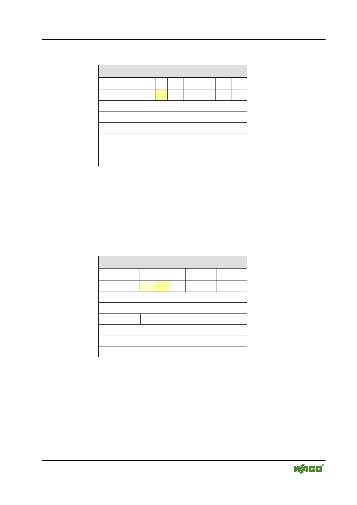
I/O Modules • 47
Special Modules
Table 17: Mailbox query
Mailbox query
Byte 27 26 2524 23 22 21 20
0 0 0 1 0 0 0 0 0
1 -
2 Opcode
3 T -
4 Query parameter byte 0
… …
max. 19 Query parameter byte 15
Opcode
T
- command code of the mailbox request
- toggle bit - A mailbox request is started with a change.
In the mailbox response, bits 25 and 26 of the status byte are set. Bit 25 confirms the activated mailbox.
Bit 26 can be set. This indicates a general error since the modules are in configuration mode and have no valid network configuration. Unused bytes of the
response are set to 0.
Table 18: Mailbox response
Mailbox response
Byte 27 26 25 24 23 22 21 20
0 0 0/1 1 0 0 0 0 0
1 -
2 Opcode (mirrored)
3 T Return value
4 Response parameter byte 0
… …
max. 19 Response parameter byte 15
Opcode
T
Return value
The mailbox is unmasked if there is an existing wireless connection to the local device; this is signaled to the other party by bit 22. This warns of potentially aged data due to the uncovered mailbox (see Section 2.1.1.8.2.1).
WAGO-I/O-SYSTEM 750
I/O Modules
- mirrored command code of the mailbox request
- toggle flag - A mailbox request is confirmed by a change.
- Status/error of the mailbox request
Page 48

48 • I/O Modules
Special Modules
2.1.1.8.2.3 Access Procedure
Unmasking the mailbox by setting bit 5 in the control byte is required for executing mailbox commands. The module confirms this by setting bit 5 in the
status byte. In order to execute a mailbox command, query parameters and the
opcode of the command must be written in the output process image. Since a
change in the opcode and/or the toggle bit is a trigger for the processing of a
command, the query parameters must be written into the output process image
either at the same time or previously.
The module confirms the processing of the command by inserting a response
telegram in the mailbox area of the internal data bus input data. The response
evaluation must occur at the same point at which the opcode and toggle bit are
identical with the query contents; i.e., these are mirrored. The processing time
in the module may require several bus cycles. Some special commands trigger
a longer process (e.g., search for devices within range). For these commands,
the module's response confirms that the process has begun. The results of
longer lasting processes can be queried after completion by other commands.
The toggle bit is necessary for executing two mailbox commands with the
same opcode (but possibly differing parameters) one after the other.
Note
The use of mailbox commands implements a confirmed service. The module
provides information via return value on the successful execution of the
command or errors that occur. If errors occur, it may be that not all response
bytes contain valid data.
The following diagram (see Figure 17) describes the request and processing of
a mailbox command. The process data are displayed as follow in this case:
[ parameter 0-x | toggle | opcode | internal byte | control/status byte ]
Initially, any process data may be present in the output and input process image. After entering the opcode and/or toggle bit, as well as switching the mail-
5
box on using bit 2
in the control byte, the mailbox command is transmitted
and a query is started. In the input process image, the query is received, processed and confirmed with bit 2
5
. This confirmation and the new process data
are sent to the output process image. Here, the data is evaluated. The next
command can be transmitted.
WAGO-I/O-SYSTEM 750
I/O Modules
Page 49

I/O Modules • 49
Special Modules
PIO Processing Times PII
Cyclically updated process data
[XX.XX.XX.XX.XX.XX.XX.XX.XX.XX].00.00
Switching on the mailbox, mailbox command IDLE
(0x00)
[XX.XX.XX.XX].[00.00.00.00].[00.00].00.20
Request for mailbox command GetLinkSignalStrength (0xD7)
[XX.XX.XX.XX].[00.00.00].[20].[00.D7].00.20
This queries the receive signal strength for the first slot.
The mailbox includes:
Opcode
Toggle byte
Argument
Filling byte
..
Request for mailbox command GetLinkSignalStrength
(0xD7)
[XX.XX.XX.XX].[00.00.00].[28].[80.D7].00.20
This queries the receive signal strength with a false
argument. The mailbox includes:
Opcode
Toggle byte
Argument
Filling byte
0xD7
0x00
0x20 (Slot 1)
0x00 (for unused mailbox bytes)
0xD7
0x80 (toggle bit set to execute new
command)
0x28 (invalid)
0x00 (for unused mailbox bytes)
.
Cyclically updated process data (mailbox masked)
[XX.XX.XX.XX.XX.XX.XX.XX.XX.XX].00.00
Cyclically updated process data
[XX.XX.XX.XX.XX.XX.XX.XX.XX.XX].00.00
Response to mailbox command IDLE
(0x00)
[XX.XX.XX.XX].[00.00.00.00].[00.00].00.60
Response to mailbox command GetLinkSignalStrength
(0xD7)
[XX.XX.XX.XX].[00.00.00].[1B].[00.D7].00.60
Response to the query:
Opcode (mirrored)
Toggle bit, return value
Argument
Filling byte
Response to mailbox command GetLinkSignalStrength
(0xD7)
[XX.XX.XX.XX].[00.00.00.00].[83.D7].00.60
Response to the query:
Opcode (mirrored)
Toggle bit, return value
Argument No argument since invalid
Filling byte
Since an invalid index was used with 0x28, there are no
arguments in the response.
0xD7
0, 0x00
0x1B (value of the signal
strength of the queried
slot)
0x00 (for unused mailbox
bytes)
0xD7
1, 0x03
call up
0x00 (for unused mailbox
bytes)
Cyclically updated process data (mailbox masked)
[XX.XX.XX.XX.XX.XX.XX.XX.XX.XX].00.00
Figure 17: Example of mailbox communication g064416d
WAGO-I/O-SYSTEM 750
I/O Modules
Page 50

50 • I/O Modules
Special Modules
2.1.1.8.2.4 Mailbox Commands and Return Values
In Appendix 6.1, you will find an overview of all mailbox commands sorted
according to groups and opcodes (see Appendix 6.1.1) or alphabetically according to the names of the commands (see Appendix 6.1.2).
A detailed description of each command can be found in the reference to Appendix 6.3.
If a mailbox command is executed, the command is confirmed. The return
value is transmitted in byte 3 of the process data. Section 2.1.1.8.1.1 summarizes the possible return values.
WAGO-I/O-SYSTEM 750
I/O Modules
Page 51

I/O Modules • 51
Special Modules
2.1.1.8.3 Register Communication
Register communication allows direct access to 64 module registers. These
serve exclusively for module configuration on the lowest level. Register communication is active if bit 27 is set.
The contents of the register follow the control/status and internal bytes in
D0/D1 of the input/output process image:
Table 19: Setup of the process image during register communication
Byte Word Input process image Output process image
0 0 Control byte Status byte
1 Internal byte Internal byte
2 1 D0 D0
3 D1 D1
2.1.1.8.3.1 Configuration of the Control and Status Bytes
The status byte is configured as follows during register communication:
Table 20: Configuration of the control byte
Control byte
Bit 27 26 2
Value/
Description
Bit Value Description
20 - 25
Reg. no. Register number (for example, 56 or 57)
0 Read access 26
1 Write access
27 1 Always 1 during register communication
(Switch between process data communication and register communication)
Read/
1
Write
5
2
4
2
3
2
Register number
2
2
1
2
0
WAGO-I/O-SYSTEM 750
I/O Modules
Page 52

52 • I/O Modules
Special Modules
Active register communication is confirmed by the module in the status byte:
Table 21: Configuration of the status byte
Status byte
Bit 27 26 2
5
2
4
2
3
2
2
2
1
2
0
Value/
Description
Bit Value Description
20 - 25Reg. no. Register number
26 0 always 0
27 1
1 0 Register number
Always 1 during register communication (confirmation by the bus module)
(Switch between process data communication and register communication)
2.1.1.8.3.2 Parameter Channel for Data Exchange
A common data channel (parameter channel) between the application and the
I/O module is used to exchange parameter sets acyclically and have them
checked by the complex I/O module. In order to access to all available interfaces of a coupler/controller, the parameter channel is mapped to the existing
register model. Currently, the parameter channel can be operated with the following interfaces:
• Manual configuration via access to the process image using the con-
trol/status byte
• Software-supported configuration over the asynchronous serial interface of
the coupler/controller (e.g., via WAGO-I/O-CHECK, WAGO-I/O-PRO
CAA)
The parameter channels are mapped through the register of the complex module. The following registers are relevant for the user in this case:
• Register 56: Here, parameter data is stored word by word.
• Register 57: Here, the communication control for the data is performed.
The structure of registers 56 and 57 is described in Section 2.1.1.8.3.3.
WAGO-I/O-SYSTEM 750
I/O Modules
Page 53

I/O Modules • 53
Special Modules
2.1.1.8.3.3 Register Structure
2.1.1.8.3.3.1 Parameter Data (register 56)
Register 56 contains the parameter data to be read or written. Depending on
the access type, either the I/O module (read parameters) or the fieldbus coupler (write parameters) will write data to the register.
Table 22: Register 56
Register 56
Bit 27 26 25 24 23 22 21 20
Parameter
Bit 215 214 213 212 211 210 29 28
Parameter
PRM0…PRM15 Parameter data bit 20 to Bit 215
PRM7 PRM6 PRM5 PRM4 PRM3 PRM2 PRM1 PRM0
PRM15 PRM14 PRM13 PRM12 PRM11 PRM10 PRM9 PRM8
2.1.1.8.3.3.2 Communication Control (register 57)
Parameter channel control and diagnostics are performed via register 57.
Table 23: Register 57
Register 57
Bit 27 26 25 24 23 22 21 20
Query parameter
Response parameter
Bit 215 214 213 212 211 210 29 28
Query parameter
A7 A6 A5 A4 A3 A2 A1 A0
A7 A6 A5 A4 A3 A2 A1 A0
TGL_
MS
PRM_
RW
MORE_
PRM
RES RES RES RES RES
Response parameter
Query parameter Information is written by the application and read by the module
Response parameter Information is written by the application and read by the module
WAGO-I/O-SYSTEM 750
I/O Modules
TGL_
SM
TIME
OUT
BUF_O
VF
PRM_
ERR
RES RES RES RES
Page 54

54 • I/O Modules
Special Modules
Parameter Value
range
A0 … A7 0 ...255 Word address of the parameter to be read/written.
TGL_MS FALSE,
TRUE
FALSE Parameter data of A7…A0 are read PRM_RW
TRUE Parameter data are written to A7…A0
FALSE End of parameter transmission MORE_PRM
TRUE More parameter data to follow
TGL_SM FALSE,
TRUE
TIMEOUT
FALSE The transmission of the parameters has been completed
TRUE The maximum time for the transmission of the parameters
Description
Toggle bit to release new instructions from the application to
the module. If TGL_SM and TGL_MS have the same status,
no new instruction has been released yet. If the flags have
different statuses, a new instruction has been released and is
currently being processed.
Toggle bit indicating that a parameter sent by the module has
been transferred. If TGL_SM and TGL_MS have different
statuses, the corresponding instruction is processed by the
module. If both flags have the same status, the instruction for
the parameter that was sent or requested is completed.
within the stipulated time (parameter address 0).
between I/O module and application was exceeded.
BUF_OVF
PRM_ERR
RES FALSE Reserved for expansions
FALSE Access to the write or read buffer of the module was ap-
proved.
TRUE Parameters outside the write or read buffer have been ac-
cessed.
FALSE The parameter/all parameters previously transmitted are
valid.
TRUE At least one transmitted parameter was defective. The flag
can either be set after each parameter that is received or after
the transmission of the parameters is completed.
WAGO-I/O-SYSTEM 750
I/O Modules
Page 55

I/O Modules • 55
Special Modules
2.1.1.8.3.4 Parameter Sets
For use of the parameter channel; parameter sets are defined and indexed using parameter addresses (A7...A0). Module-specific parameters (parameters 0
through 249) and general system parameters (parameters 250 through 255) are
differentiated.
2.1.1.8.3.5 Process of Parameter Transmission
The parameter data exchange between the application and bus module is made
via request/response process. The application initiates an instruction using the
toggle bit (TGL_MS != TGL_SM). Afterward, the application queries the
communication control register (R57) of the module until the module confirms
the execution of the instruction (TGL_SM == TGL_MS).
The possible instructions to the parameter interface of the bus module are
listed in the following.
2.1.1.8.3.5.1 Calculate the Maximum Parameter Data of the Bus Module (System Parameters)
Query (application)
Parameter Value Description
TGL_MS != TGL_SM Enter instruction
PRM_RW = FALSE Read access
A0…A7 255 Address of parameter data length
Response (bus module)
Parameter Value Description
TGL_SM == TGL_MS Instruction completed
A0…A7 255 Address of parameter data length mirrored
PRM0...
PRM15
N Number of parameter data in address area 0...(n-1),
n ∈ {N < 250}
WAGO-I/O-SYSTEM 750
I/O Modules
Page 56

56 • I/O Modules
Special Modules
2.1.1.8.3.5.2 Set Factory Settings (System Parameters)
Query (application)
Parameter Value Description
TGL_MS != TGL_SM Enter instruction
PRM_RW = TRUE Write access
A0...A7 255 Address of factory settings
Response (bus module)
Parameter Value Description
TGL_SM == TGL_MS Instruction completed
A0...A7 255 Set address of factory setting, mirrored
By writing 255 on the parameter address, the factory setting of the internal
data bus subsystem for the Bluetooth® module is restored. This includes the
size of the process image and mailbox. The settings of the Bluetooth® subsystem can only be accessed through the mailbox interface and can be separately
reset to standard values via mailbox command (see Appendix 6.3.5.22).
2.1.1.8.3.5.3 Read/Write Parameters (Module-Specific)
Query (application)
Parameter Value Description
TGL_MS != TGL_SM Enter instruction
= FALSE Read access PRM_RW
= TRUE Write access
= FALSE Parameter data transmission is completed. MORE_PRM
= TRUE More parameter data to follow.
A0...A7 0...(n-1) Parameter address
PRM0... PRM15 0 ...65535 Parameter data write access
WAGO-I/O-SYSTEM 750
I/O Modules
Page 57

I/O Modules • 57
Special Modules
Response (bus module)
Parameter Value Description
TGL_SM == TGL_MS Instruction completed
A0...A7 0...(n-1) Address parameter data mirrored
TIMEOUT FALSE, TRUE Monitoring time expired
BUF_OFL FALSE, TRUE Access outside the module parameter range
PRM_ERR FALSE, TRUE Parameter/parameter set error
PRM0... PRM15 0 ...65535 Parameter data read access
The module uses the error flags TIMEOUT, BUF_OV and PRM_ERR to report errors during the parameter data exchange.
After the last parameter data has been sent to the module (MORE_PRM =
FALSE), the module checks the entire parameter set and accepts it if everything is correct. Otherwise, the module returns a parameter error (PRM_ERR
= TRUE).
2.1.1.8.3.5.4 Example: Configuring Bluetooth® Process Data and Mailbox
Only parameter 0 of the Bluetooth® module can be changed by the user. This
affects the configuration of the size of the process image and mailbox.
Query (application)
Parameter Value Description
TGL_MS != TGL_SM Enter instruction
PRM_RW = TRUE Write access
MORE_PRM = FALSE Parameter data transmission is completed.
A0…A7 0 Parameter address
PRM0...PRM7 DATA_LEN 12, 24 or 48 bytes of data length
PRM8... PRM14 MBX_LEN 6, 12 or 18 bytes of mailbox size
PRM15 MBX_MODE TRUE - Mailbox covers the process data (by set-
ting bit 2
5
in the control byte)
Response (bus module)
Parameter Value Description
TGL_SM == TGL_MS Instruction completed
A0...A7 0 Address parameter data mirrored
TIMEOUT FALSE, TRUE Monitoring time expired
BUF_OFL FALSE, TRUE Access outside the module parameter range
PRM_ERR FALSE, TRUE Parameter/parameter set error
WAGO-I/O-SYSTEM 750
I/O Modules
Page 58

58 • Configuration of a Bluetooth® Piconet
Special Modules
3 Configuration of a Bluetooth® Piconet
To configure a piconet, connect 2 to 8 Bluetooth® devices with each other. In
doing so, there is some important framework data to consider:
Is real-time or ad hoc communication beneficial for your application?
Is the data that you wish to transmit time-critical data?
Also important, how many WAGO Bluetooth® modules and how many external Bluetooth® modules are to communicate with each other: If only WAGO
devices are to be connected with each other, you can connect one master with
seven slaves. This only applies for the real-time profile, however. In the ad
hoc profile, you can connect up to six WAGO slaves. If you also want to use
external Bluetooth® devices in your piconet, choose the ad hoc profile. In this
profile, seven WAGO devices and six external devices can be linked, but only
a maximum of seven devices can actively exchange data at the same time.
In preparation for configuration, note which Bluetooth® device will take over
which role (master/slave), what the MAC addresses of the devices are and
which communication profile is to be set (real-time/ad hoc). This makes the
overview easier for you.
These considerations will determine the allocation of the devices to available
slots in the master process image. These are available for the data exchange.
In a later step, you will determine the number of bytes (cutoff size) for each
slot that should be available in the master process image for data exchange.
Only the process data allocated to the slots will be transmitted wirelessly.
Therefore, your configuration will work most efficiently if slave devices are
set to the smallest possible process image size. The smallest possible process
image size for a slave corresponds to the smallest setting for its process image
size, which is the same or larger [2 + cutoff of the corresponding slot].
After drafting your configuration in the previous steps, you can now synchronize the device configurations to each other. To do this, first configure the
process image and mailbox size.
The mailbox size determines which mailbox commands can be executed. To
configure with WAGO-I/O-CHECK or building blocks of the WAGO-I/OPRO CAA, you can choose each available mailbox size independently of limitations of the fieldbus. For a successful configuration, a mailbox size of at
least 12 bytes is necessary. If you want all diagnostic commands available to
the full extent, set it for 18 bytes. If you are using a fieldbus over which less
than 20 bytes per data element can be transmitted (e.g. CANopen), you should
reduce the mailbox size again to an appropriate size after successfully completing the device configuration.
If you plan to use the mailbox during ongoing communication; e.g., for diagnostic purposes, take note that when unmasking the mailbox, process data may
be temporarily covered (see Section
WAGO-I/O-SYSTEM 750
I/O Modules
2.1.1.8.2.1, "Aging of data by the mail-
Page 59

Configuration of a Bluetooth® Piconet • 59
Special Modules
box"). In this case, you can also configure in such a way that the first slot has
no device allocated to it and the size of the first slot corresponds to the mailbox size. This does mean, however, that one less device can be linked, but the
up-to-dateness of the process data is not dependent on the masking or unmasking of the mailbox. But this is only possible for the module configured as the
master since slave process images always consist of only one individual slot
(in the master) and these do not begin until the third byte.
After configuring the process image and mailbox size, you can continue with
the device configuration. Please make sure that the module is in configuration
mode for the remainder of the steps.
Assign each device its intended role (master or slave). For each slave, enter
the master in the first slot in the list of allowed WAGO devices. For the master, all intended slaves are assigned slots in the list of allowed WAGO or external devices. For each slot, set the planned data width (cutoff).
For master/slave communication over Bluetooth®, make sure that the settings
for encryption, authentication and PIN are identical in the devices. For maximum security, it is recommended that you keep the factory setting for "Encryption" at "On" and "Authentication" at "Password". The preset password,
“0000” should be changed to a project-specific password.
At the end of the device configuration process, you will change to communication mode - in the ad hoc or real-time profile, depending on the type of
slaves. With correct configuration, devices within range should automatically
establish a connection to each other. The establishment of a connection is especially fast if you first startup the slaves and then the master.
As soon as the connections are established, master and slaves exchange data
with each other, depending on the slot configuration. You can continue to set
mailbox commands in communication mode as well. An example being to
change the operating mode again or to query diagnostic information.
Section
WAGO-I/O-CHECK and the process of configuring a Bluetooth
4 below describes the Bluetooth®-specific configuration interface
®
module 750-
644. In Appendix 6.5, concrete example configurations are also provided.
WAGO-I/O-SYSTEM 750
I/O Modules
Page 60

60 • Tools for Configuring and Operating
Special Modules
4 Tools for Configuring and Operating
The Bluetooth® module is configured using the WAGO-I/O-CHECK software
(Version 3 or later). The software's basic functionality is described separately
in the WAGO-I/O-CHECK documentation.
Additional Information
You can obtain the WAGO-I/O-CHECK software (Version 3 or later) on CD
ROM using order number 750-302. The CD ROM contains all programming
files for the application. The documentation for the WAGO-I/O-CHECK software can be obtained online at http://www.wago.com under Documentation !
WAGO Software 759 ! WAGO-I/O-CHECK.
The specific parameterization dialog for the Bluetooth® module is opened by
right clicking on a Bluetooth
®
module and selecting the menu item Settings
(see Figure 18).
Figure 18: User interface of WAGO-I/O-CHECK g064417e
The content of the parameterization dialog (see Figure 19) forms the basis of
the following description.
Figure 19: Bluetooth® parameterization dialog g064418e
WAGO-I/O-SYSTEM 750
I/O Modules
Page 61

Tools for Configuring and Operating • 61
Configuring and Operating with WAGO-I/O-CHECK
4.1 Configuring and Operating with WAGO-I/O-CHECK
4.1.1 User Interface
The user interface of the Bluetooth® parameterization dialog is divided into the
following areas (see Figure 20):
Figure 20: User interface of the Bluetooth® parameterization dialog g064419e
1. Title bar (see Section
2. Symbol bar (see Section
3. Navigation (see Section
4. Mode assignment (see Section
4.1.1.1)
4.1.1.2)
4.1.1.3)
4.1.1.4)
5. Parameterization area (see Section 4.1.1.5)
6. Status display (see Section 4.1.1.6)
The areas are explained in more detail in the following Sections.
WAGO-I/O-SYSTEM 750
I/O Modules
Page 62

62 • Tools for Configuring and Operating
Configuring and Operating with WAGO-I/O-CHECK
4.1.1.1 Title Bar
The position of the module within the node (as well as its name and item and
version number) are displayed in the title bar of the parameterization dialog.
4.1.1.2 Symbol Bar
®
The symbol bar in the Bluetooth
ing buttons (see
Figure 21: Buttons in the Bluetooth® parameterization dialog g064420e
Figure 21):
parameterization dialog contains the follow-
Table 24: Buttons in the Bluetooth
Button Description
[Close]
Closes the active window. If you have changed settings, you will be asked to
accept the values in the I/O module.
[Open]
Opens window to select a parameter file. Device settings are read from the parameter file and transferred to the connected I/O module.
[Save]
Opens a window to select a parameter file. The device settings are saved in the
parameter file.
[Read]
Reads the current settings from the connected I/O module and displays them in
this window.
[Write]
Transfers the settings displayed in this window to the connected I/O module.
[Default]
Overwrites the locally saved configuration with the factory settings.
[Restart]
Restarts the host controller.
Attention: All wireless connections are broken off.
[Flash]
Writes the current configuration of the host controller to the flash memory and
restarts it. Attention: All wireless connections are broken off.
[Data Frame]
Sets process size and mailbox size.
[Help]
Displays help for this window.
®
parameterization dialog g064421e-30e
WAGO-I/O-SYSTEM 750
I/O Modules
Page 63

Tools for Configuring and Operating • 63
Configuring and Operating with WAGO-I/O-CHECK
4.1.1.3 Navigation
You can toggel between the different configuration areas of the module by using the navigation on the left side of the screen (see Figure 22).
Figure 22: Navigation between configuration areas g064431e
Choose between the following menu items (see Table 25):
Table 25: Navigation between configuration areas g064432e-36e
Menu item Description
[Settings]
Opens a page with general module parameters such as device name, MAC
address, device role, etc. These parameters can be altered here and loaded
to the module (see Section
[Net Forming]
Opens a page with device lists. Here, configured and bound devices
within range are displayed with MAC address and name and configured
(see Section
[PI Mapping]
Opens a page for the allocation of slave process data to slots in the master
(see Section
[Block Transfer]
Opens a page for viewing the process data during uploading and
downloading. The menu entry "Block transfer" is only displayed in the
configuration mode (see Section
[Diagnostics]
Opens a page with comprehensive diagnostic information on the status of
the module and the network as well as the connection quality (see Section
4.1.1.5.5, "Diagnostics"). The menu entry "Diagnostics" is only displayed
in the communication mode.
4.1.1.5.2, "Net Forming").
4.1.1.5.3, "PI Mapping").
4.1.1.5.1, "Settings").
4.1.1.5.4, "Block Transfer").
WAGO-I/O-SYSTEM 750
I/O Modules
Page 64

64 • Tools for Configuring and Operating
Configuring and Operating with WAGO-I/O-CHECK
4.1.1.4 Mode Assignment
Device Role is displayed in the top area, indicating whether the currently configured module is a master or a slave.
The lower area, Operation Mode is used to assign the mode to the locally
connected module. Using the buttons, choose whether the module is to be operated in either the configuration or communication mode (real-time or ad hoc
profile) (see Figure 23).
Figure 23: Changing mode g064437e
Choose between the following menu items:
Table 26: Navigation between configuration pages g064438e-42e
Menu item Description
"Slave" or "Master"
Displays the currently assigned device role of the local module.
[Configuration]
Switches the locally connected module to the configuration mode.
[Communication (Ad-hoc)]
Switches the locally connected module to the communication mode
(ad hoc profile).
[Communication (Realtime)]
Switches the locally connected module to the communication mode (real-time
profile).
WAGO-I/O-SYSTEM 750
I/O Modules
Page 65

Tools for Configuring and Operating • 65
Configuring and Operating with WAGO-I/O-CHECK
4.1.1.5 Parameterization Area
In the parameterization area, the Bluetooth® module is configured and prepared for communication. This is described in further detail in the following
sections.
Changing and saving data
To change settings in the Bluetooth® module, adjust the values displayed in
the parameterization area. Altered settings are labeled with a change symbol
. This indicates that the displayed values are no longer the same as the originally queried values of the module. To transfer the new values to the module,
click on the [Write] button. The change symbols will disappear.
In this writing process, the values of the module are first temporarily saved so
that clicking on [Restart] can delete the changes again. In this case, you
should update the graphic display of the values after restart by clicking on
[Read].
To save transferred value changes permanently (flash process) without changing the operating mode, click on [Flash]. You may also change the module to
another operating mode. When you do this, transferred changes are automatically and permanently saved. For example, you can change the module over to
the communication operating mode (real-time) after completing configuration
under Net Forming. This will cause the altered configuration to be saved, and
the module attempts immediately to exchange data with the configured partner
devices.
WAGO-I/O-CHECK
Preview for module's settings
[Save]
Bluetooth
WAGO Module
Buffer for new settings (volatile)
[Flash] or change of operation mode
(when the configuration is completed)
[Read] or open
the dialog window
®
Module's start-up
or restart
Figure 24: Saving the configuration g064471e
WAGO-I/O-SYSTEM 750
I/O Modules
Memory of module's settings (non-volatile)
Page 66

66 • Tools for Configuring and Operating
Configuring and Operating with WAGO-I/O-CHECK
4.1.1.5.1 Settings
Settings displays general module parameters (see Figure 25).
Figure 25: Settings g064418e
The following parameters can be changed and loaded to the module.
Table 27: Navigation between configuration pages
Name Entry/Selection Description
MAC Address _ _ : _ _ : _ _ : _ _ : _ _ : _ _ MAC address of the device
Master Assignment of the master role Device Role
Slave Assignment of the slave role
Class of Device
CoD Subclass Bluetooth® RF Transceiver WAGO CoD subclass
WAGO Speedway 767
WAGO System 763
WAGO-I/O-SYSTEM 757
WAGO-I/O-SYSTEM 755
WAGO-I/O-SYSTEM 753
WAGO-I/O-SYSTEM 750
WAGO Class-of-Device
(for Bluetooth
System 750" is set)
®
, "WAGO-I/O-
On Switch on encryption Encryption
OFF Switch off encryption
WAGO-I/O-SYSTEM 750
I/O Modules
Page 67

Tools for Configuring and Operating • 67
Configuring and Operating with WAGO-I/O-CHECK
Name Entry/Selection Description
Authorization
OFF No authorization required.
Password For external devices, password entry
is required. The "Link key" for the
authorization must be recalculated
for each established connection.
Link key The "Link key" for the authorization
does not have to be recalculated.
After a first-time connection, entering the password is no longer necessary for an external device either.
Name Entry as ASCII characters,
length dependent on mailbox
Name of the local module (Blue-
®
Device Name)
tooth
size (max. 16 characters)
Password Entry as ASCII characters,
Password of the local module
length dependent on mailbox
size
Reconnect Time _ Smallest time interval in seconds
between two attempts to connect
IP Address _ _ _ ._ _ _ ._ _ _ ._ _ _ The local TCP/IP address
IP Subclass _ _ _ ._ _ _ ._ _ _ ._ _ _ The local TCP/IP subnet mask
LocalUpTime _ _ days, _ _ hours., _ _ min. Operating time of the module since
the last restart
Version of boot loader _ _ . _ _ ._ _ Version number of the boot loader
Firmware version _ _ . _ _ ._ _ Version number of the firmware
Version of configura-
_ _ . _ _ ._ _ Configuration version number
tion
Baseband controller _ _ . _ _ ._ _ HCI version of the baseband con-
troller
WAGO-I/O-SYSTEM 750
I/O Modules
Page 68

68 • Tools for Configuring and Operating
Configuring and Operating with WAGO-I/O-CHECK
4.1.1.5.2 Net Forming
"Net Forming" refers to the configuration of the Bluetooth® network. On the
"net forming" side, devices are manually entered or automatically sought and
bound for later communication.
Figure 26: Net forming g064443e
On the left side, all devices within range are displayed. You update the list by
clicking on the [Search] button.
Depending on the option selected, you can limit the search for devices. The
Class-of-Device (CoD) is used as a criterion for filtering search results.
Select All to search for any Bluetooth® devices within range in the environment.
Select WAGO 750 to search for all WAGO devices of the model series 750
within range.
WAGO-I/O-SYSTEM 750
I/O Modules
Page 69

Tools for Configuring and Operating • 69
Configuring and Operating with WAGO-I/O-CHECK
Select Other to manually enter which CoD should be used to filter the search
results (see Figure 27).
Figure 27: Filter according to device classes g064489e
To the right on the "net forming" page, the configured devices are displayed in
two lists. The upper list contains WAGO devices using the real-time profile.
The lower list contains both WAGO and/or external devices using the ad hoc
profile.
Selected devices within range are added to the real-time or ad hoc list by using
the [>>] button. MAC addresses or device names can also be moved to the ad
hoc or real-time list by drag & drop from the list of devices within range.
Selected devices are deleted from the real-time or ad hoc list using the [<<]
button. Deleting the device is also possible by double-clicking on the respective MAC address.
The tables on the Net forming page are filled as follows:
Table 28: Table identifiers in "Net forming"
Name Entry/Selection Description
IS _ _ Device ID for devices within range
MAC Address _ _ : _ _ : _ _ : _ _ : _ _ : _ _ MAC address of the device
Device name ASCII characters Device name (cannot be changed)
Slot _ Slot number of allocated device
UserFriendlyName ASCII characters Name assigned to a slot (can be
changed)
Yes Bind device ("Yes") Bind
No Do not bind device ("No")
Note
Remember when assigning a "UserFriendlyName", you must display the entire length of the name; a mailbox size of 18 bytes is necessary. With a
smaller mailbox setting, the full name is actually displayed within WAGOI/O-CHECK, but not completely saved, so when the name is read back from
the module, not all the characters are displayed.
WAGO-I/O-SYSTEM 750
I/O Modules
Page 70

70 • Tools for Configuring and Operating
Configuring and Operating with WAGO-I/O-CHECK
4.1.1.5.3 PI Mapping
To undertake settings on the "PI mapping" (process image mapping) page, the
process image size of the master must first be set.
Use the [Data Frame] button in the symbol bar to open the dialog for entering
the process image and mailbox sizes (see Figure 28).
Figure 28: Determine data framework g064444e
The following settings are possible (see Table 29):
Table 29: Determine data framework
Toggle field Settings
Process image size
Mailbox size
* Standard setting
Button Description
12 bytes, 24 bytes, 48 bytes*
6 bytes, 12 bytes, 18 bytes*
[Apply]
Transfers the altered parameters to the module's permanent memory. A
software reset is conducted so that the changes take effect. The dialog
remains open.
[Default]
Selects the standard setting for this module. Then transfer the parameters
to the permanent memory of the module by using the [Apply] button.
[Close]
Ends the parameterization dialog without transferring any altered parameters to the permanent memory of the module.
Note
Please note that the structure of the process image changes when the process image size or mailbox size is changed. Therefore, changes in the configuration of
the superordinate control may be necessary.
On the "PI mapping" page, the slave process data is allocated to the slots in
the master (see
Figure 29). Up to 46 bytes of the process image are available
for this purpose (depending on which process image size was set in the "Data
framework" dialog). The control/status byte and internal byte are not taken
into consideration here.
WAGO-I/O-SYSTEM 750
I/O Modules
Page 71

Tools for Configuring and Operating • 71
Configuring and Operating with WAGO-I/O-CHECK
Figure 29: PI mapping g064445e
On the left side, slots 1 through 7 for the real-time profile are displayed (for
WAGO devices only). The right side displays slots 8 through 13 for the ad hoc
profile (for WAGO and external devices). Each line labels a slot ( Figure 30):
Figure 30: Display of a slot g064446x
WAGO-I/O-SYSTEM 750
I/O Modules
Page 72

72 • Tools for Configuring and Operating
Configuring and Operating with WAGO-I/O-CHECK
Table 30: Display of a slot g064447x-51x
Setting Description
Identification of slots (1…7 real-time, 8…13 ad hoc)
Display of the "UserFriendlyName", if provided
Selection of slot color for the graphic display in the lower
area (see
Sliding controller for the size of the process data in bytes
(cutoff size) assigned to a slot
Entry field for the size of the process data in bytes (cutoff
size) assigned to a slot
Offset in bytes at the beginning of the slot
(without control/status and internal bytes)
Figure 29)
The master process image with the distribution of the slots is graphically displayed below the slot configuration (see Figure 31).
Figure 31: Slot allocation g064452e
WAGO-I/O-SYSTEM 750
I/O Modules
Page 73

Tools for Configuring and Operating • 73
Configuring and Operating with WAGO-I/O-CHECK
4.1.1.5.4 Block Transfer
This page displays the configuration block during uploading and downloading
of the process data (see Figure 32). The menu item Block Transfer is only
visible in the configuration mode.
Figure 32: Block transfer g064453e
Choose between the following menu items:
Table 31: Block transfer g064454e-58e
Menu item Description
Upload
v
[Configuration]
Displays the configuration transferred from the module to the application.
[Search Results]
Displays the list of MAC addresses found during a search.
[Local Name]
Displays the complete local name of the module (in menu item "Settings", the
name may be incomplete due to insufficient mailbox size).
[Password]
Loads the set password.
[Remote Name]
Displays the device names of the connected modules. By entering an ID (see
page on Net forming), the device name of a special Bluetooth® device is
displayed.
WAGO-I/O-SYSTEM 750
I/O Modules
Page 74
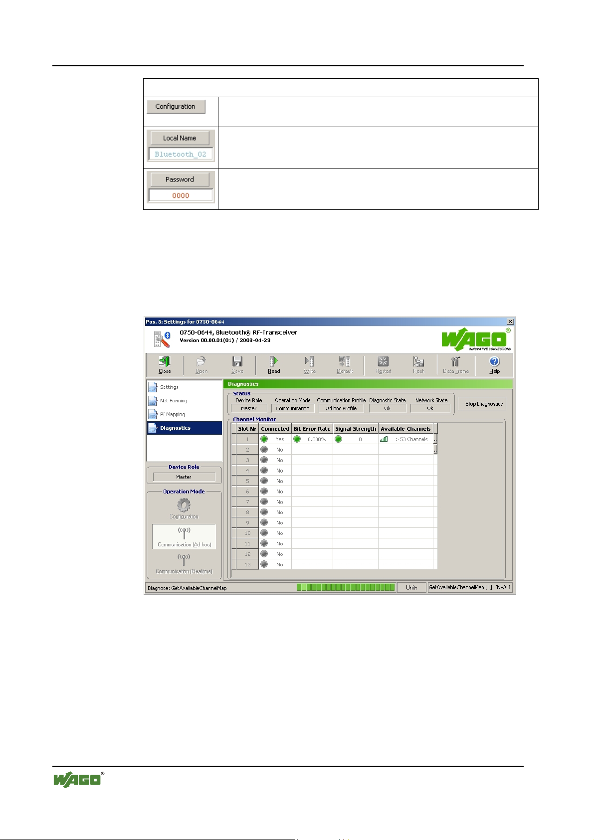
74 • Tools for Configuring and Operating
Configuring and Operating with WAGO-I/O-CHECK
Download
[Configuration]
Writes the configuration to the module.
[Local Name]
Writes the local name to the module. The name can be entered in the entry
field.
[Password]
Writes the password in the locally connected module. The password can be
entered in the entry field.
4.1.1.5.5 Diagnostics
This page displays diagnostic information on the module status, the network
and the quality of the connection (see Figure 33). The menu item
Diagnostics is only visible in the communication mode.
Figure 33: Diagnostics g064459e
WAGO-I/O-SYSTEM 750
I/O Modules
Page 75

Tools for Configuring and Operating • 75
Configuring and Operating with WAGO-I/O-CHECK
The following displays are summarized under the header "Status"
(see Table 32):
Table 32: General status display
Status Value Description
Slave Device takes over the role of "slave" Device Role
Master Device takes over the role of "master"
(see also Appendix
Operating Mode Communication Device is in communication mode
(see also Appendix
Real-time profile Device is in the communication profile "real-time" Communication
Profile
Ad hoc profile Device is in the communication profile "ad hoc"
6.3.5.20, "GetLocalDeviceRole")
6.3.3.2, "GetLocalOperationMode")
Diagnostic State
Ok No warnings/errors
Warning Warning
Error General error
Critical defect Critical error (for details see Appendix
6.3.6.1, "GetLo-
calDeviceStatus")
Network Status
Ok Configured network is established.
Inconsistent Not all configured connections are established.
Defective Configured network is (still) not established.
(for details see Appendix
[Start Diagnostics]
Start value monitoring
[Stop Diagnostics]
End value monitoring
6.3.6.2, GetNetworkStatus)
Under "Channel monitor", the transmission quality for each slot is displayed
(see Table 33):
Table 33: Status of transmission channel
Status Value Description
Slot No. Slot _ Slot Number
Connected
Bit Error Rate
WAGO-I/O-SYSTEM 750
I/O Modules
Yes Connected
No Not connected
No No device configured for this slot
0 % No bit error occurred
0.1…10% Some bit errors occurred
> 10% High bit error rate
Page 76

76 • Tools for Configuring and Operating
Configuring and Operating with WAGO-I/O-CHECK
Status Value Description
Signal Strength
Available Channels
-127...0 RSSI value/signal strength too weak
0 Signal strength very good
0...+127 Signal strength too strong
(see Appendix
< 39
39…53 Some busy/defective channels
> 53 Free/undisturbed channels (low interference)
Too many busy/defective channels
(see Appendix
6.3.6.5, "GetLinkSignalStrength")
6.3.6.6, "GetAvailableChannelMap")
Click on one of the fields of the last column of the table. A dialog with a detailed status display for the selected slot opens (see Figure 34). Choose For all
connections by checking it to query the status of all slots.
Figure 34: Status query for slots g064475e
By selecting a certain Object group, you are limiting the status reports accordingly (see Table 34).
Table 34: Object groups and possible status reports
Object Groups Status *
Whole system Ok
Wireless connections
Ok
Not specified
BER is moderate
BER is high
Less than 39 channels available
Less than 54 channels available
Connection error
Connection interrupted
WAGO-I/O-SYSTEM 750
I/O Modules
Page 77
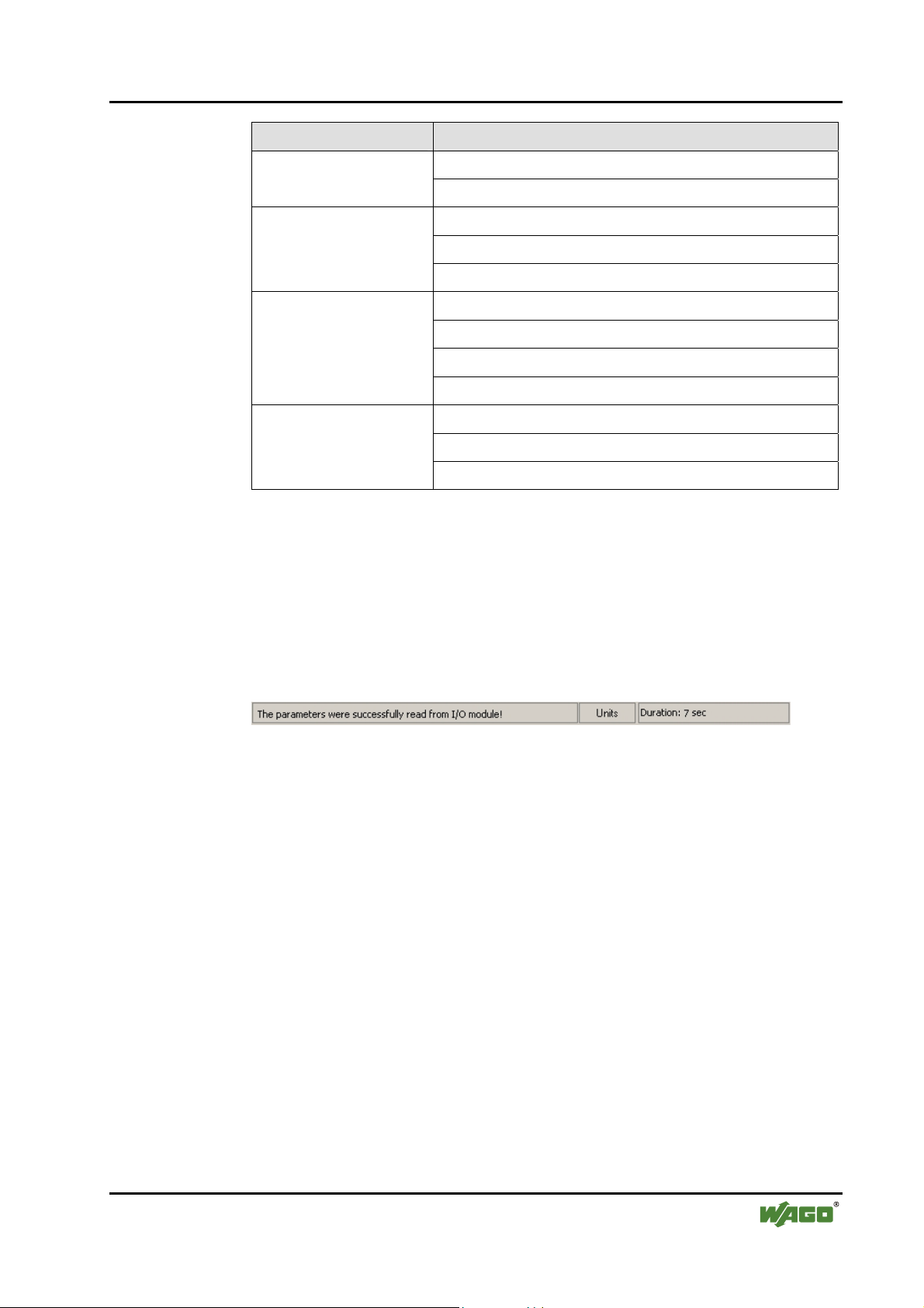
Tools for Configuring and Operating • 77
Configuring and Operating with WAGO-I/O-CHECK
Object Groups Status *
Ok Time monitoring
Watchdog
Process image
Intersystem communication
Configuration
* The meaning of the individual status reports can be found in Appendix 6.3.6.3.
You can query the status with the set parameter by using the [Execute] button.
4.1.1.6 Status Display
Status reports are given in the status display in the lower area of the parameterization dialog. The display varies depending on the page accessed:
Settings, Net forming, PI Mapping, Block Transfer and Diagnostics.
Ok
Process image is defective
A remote mailbox is active
Ok
Interruption in SPI communication
SPI is overloaded
Error in the mailbox communication
Ok
Configuration altered
Error in the network configuration
Figure 35: Status display g064460e
WAGO-I/O-SYSTEM 750
I/O Modules
Page 78

78 • Tools for Configuring and Operating
Configuring the Bluetooth® Module 750-644
4.2 Configuring the Bluetooth® Module 750-644
In order to work with the Bluetooth® module 750-644, you must first set up the
communication connection to your node. Then read the node configuration
and select the desired module in the navigation or node view.
Next, set the necessary process data and mailbox size in the parameterization
dialog. After that, you can set the desired operating mode for the master in the
process data dialog or select a slave for further processing from the list of
slave addresses.
Use the diagnostic function to eliminate configuration errors.
4.2.1 Setting the Bluetooth® Process Data and Mailbox Size
If the parameterization dialog is not open, select Settings in the context menu
of the selected module (node view or navigation).
Using the [Data Frame] button in the symbol bar, open a dialog in which you
establish the size of the process image in the internal data bus 12, 24 or 48
bytes. Choose 6, 12 or 18 bytes as the mailbox size.
Note
The available combinations of possible selections correspond to the configurations projectable by PROFIBUS or CANopen type files.
To display the standard values for the module, press the [Default] button. The
displayed values can then be changed.
Transfer the set values to the permanent memory of the module by pressing
the [Apply] button; exit the dialog by pressing [Close].
4.2.2 Setting the Mode
If the parameterization dialog is not open, select Settings in the context menu
of the selected module (node view or navigation).
The area Device Role displays whether the module is configured as master or
slave. Under that, in the Operating mode area are three buttons: [Configura-
tion], [Communication (Ad-hoc)] and [Communication (Realtime)]. Press
one of these buttons to transfer the module to the respective mode or respective profile. No explicit writing to the module is necessary.
WAGO-I/O-SYSTEM 750
I/O Modules
Page 79

Tools for Configuring and Operating • 79
Configuring the Bluetooth® Module 750-644
4.2.3 Role Assignment (Master/Slave)
The Bluetooth® module can be configured as either master or slave. Choose
Settings in the context menu of the selected module (node view or navigation)
to open the parameterization dialog. In the navigation to the left, choose Set-
tings. Click in the field to the right beside Device Role. In the dropdown
menu, select "master" to configure the module as a master or "slave" to transfer the role of slave to the module.
Click on the [Write] button in the toolbar to assign the new role to the module.
4.2.4 Search for and Display Devices within Range
Choose Settings in the context menu of the selected module (node view or
navigation) to open the parameterization dialog. Choose Net Forming in the
navigation bar. Choose the option All in the area Search for devices within
range and click on the [Search] button. The network is searched for Blue-
tooth® devices within range. Found devices are displayed in the list of devices
within range.
4.2.5 Bind new Devices
Choose Settings in the context menu of the selected module (node view or
navigation) to open the parameterization dialog. Choose Net Forming in the
navigation bar.
Enter Bluetooth® devices either manually, even if they are not (yet) present in
the network, or by using the automatic network search.
4.2.5.1 Entering Bluetooth
In the area real-time devices or ad hoc devices, mark a non-occupied MAC
address and enter the MAC address of the Bluetooth
communication is to occur. The device does not have to be in the network.
Thus, a network can first be logically constructed and the individual components started up later.
Click beside the MAC address in the Bind field and select "Yes" if you would
like to bind the device for communication.
®
Devices manually
®
device with which
WAGO-I/O-SYSTEM 750
I/O Modules
Page 80

80 • Tools for Configuring and Operating
Configuring the Bluetooth® Module 750-644
4.2.5.2 Bind Bluetooth® Devices from Network Search
Devices found by using the [Search] button are displayed in the list of devices
within range. These devices can be chosen and transferred to one of the two
lists using the [>>] button on the right side. In doing so, only WAGO devices
are added to the upper list (real-time), while the lower list can take both
WAGO devices and external devices (ad hoc).
Click beside the MAC address in the Bind field and select "Yes" if you would
like to bind the added device for communication. A total of 7 devices (6 devices in the ad hoc profile) can exchange data with a master at the same time.
Therefore, bind a maximum of 7 devices using "Bind", even if you have filled
all thirteen slots with devices.
WAGO-I/O-SYSTEM 750
I/O Modules
Page 81

Tools for Configuring and Operating • 81
Configuring the Bluetooth® Module 750-644
4.2.6 Assigning Slave Process Data to Slots in the Master
Choose Settings in the context menu of the selected module (node view or
navigation) to open the parameterization dialog. Click on PI Mapping in the
navigation area.
The master only considers parts of the individual slave process images. Select
the size of these parts (cutoff) using the slide control. As an alternative, you
can enter the number of bytes in the entry field to the side.
Please note: Only up to 7 real-time devices or up to 6 ad hoc devices can be
active at the same time. These are the only devices you can bind by selecting
Bind - "Yes" in the PI Mapping configuration area for communication. If you
bind all 13 devices and each of the 13 slots is occupied, only the first six realtime devices and the first ad hoc device will be free for communication.
4.2.7 Diagnostics
Choose Settings in the context menu of the selected module (node view or
navigation) to open the parameterization dialog. Click on Diagnostics in the
navigation area.
On this page, you will see status reports for the Bluetooth® device, the transmission channel and network displayed. Click on the [Start Diagnostics] button to constantly query current values. Click on [Stop Diagnostics] to display
the most recently received status with no further updating.
A click on the right column of the table opens a dialog window in which you
can query status information for individual slots or all existing connections by
selecting an object group and clicking [Execute].
Additional Information
An example configuration using WAGO-I/O-CHECK can be found in Appendix 6.5.
WAGO-I/O-SYSTEM 750
I/O Modules
Page 82

82 • Fieldbus-specific Additions
CANopen
5 Fieldbus-specific Additions
5.1 CANopen
5.1.1 Process Image Access
The CANopen master accesses the Bluetooth® mailbox and process data in the
coupler/controller using process data objects (PDOs).
In the standard configuration, the Bluetooth® module data is mapped in serial
PDOs. Each PDO can take up eight bytes of data. The maximum Bluetooth
®
module process image of 48 bytes therefore includes six PDOs.
control-/statusbyte
internal byte
process image
Bluetooth module
PDO for status-/control-
byte and mailbox or
cyclical data
* Example with 48 bytes process data, mailbox data 6 bytes (max. for CANopen)
……
PDO for cyclical data
PDO for cyclical data
PDO for cyclical data
PDO for cyclical data
Mailbox
data
0 1 2...7* 8...47*
0
8
PDO for cyclical data
Figure 36: PDO allocation of a Bluetooth® module g064468e
Process data
zyclicalazyclical
7
7
15
16 23
24
32 39
40 47
31
The first PDO allocated to a Bluetooth® module contains the control/status
byte, an empty byte and up to six bytes of mailbox or process data. The following PDOs contain Bluetooth® process data.
Note
If using a CANopen coupler/controller, the maximum mailbox size is lim-
WAGO-I/O-SYSTEM 750
I/O Modules
ited to six bytes.
Page 83

Fieldbus-specific Additions • 83
CANopen
With a masked or unmasked mailbox, the following allocation of the process
image size to the number of busy PDOs applies.
Table 35: Allocation of the process image size to the number of busy PDOs
Process
image
size
12 bytes 24 bytes 48 bytes
no. PDO
n+1st
PDO
n+2nd
PDO
n+3rd
PDO
n+4th
PDO
n+5th
PDO
n+6th
PDO
1 control/status byte
1 empty byte
6 bytes of mailbox or
6 bytes of process data
4 bytes process data
4 bytes empty (reserved)
free for next module 8 bytes of process data 8 bytes of process data
- free for next module 8 bytes of process data
- - 2 bytes of process data
- - 8 bytes empty (reserved)
- - free for next module
1 control/status byte
1 empty byte
6 bytes of mailbox or
6 bytes of process data
8 bytes of process data 8 bytes of process data
1 control/status byte
1 empty byte
6 bytes of mailbox or
6 bytes of process data
The 1st PDO contains a control/status byte, an empty byte and six bytes of
mailbox data with an unmasked mailbox or the first six bytes of the process
data. The following PDOs contain the remaining process data.
Note
If the mailbox is unmasked, the first six bytes of process data cannot be
accessed.
If the process image size of the Bluetooth® module is 12, the last PDO is not
completely occupied. Another module then begins with the next PDO.
5.1.1.1 Example
A node contains the following modules with input/output process image:
3 x 750-402 for every 4 bits of input data,
1 x 750-452 4 bytes of input data,
1 x 750-644 12 bytes of input and 12 bytes of output data,
1 x 750-550 4 bytes of output data,
1 x 750-452 4 bytes of input data,
1 x 750-550 4 bytes of output data,
1 x 750-452 4 bytes of input data,
1 x 750-504 4 bits of output data.
WAGO-I/O-SYSTEM 750
I/O Modules
Page 84
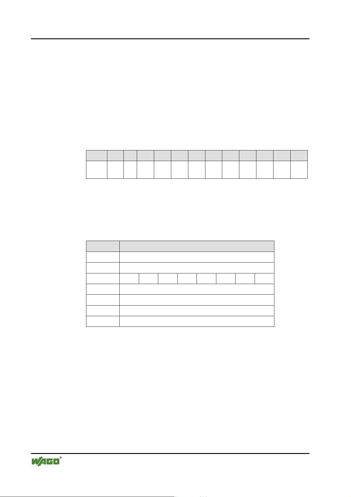
84 • Fieldbus-specific Additions
CANopen
PDOs 1 through 4 are, according to the standard for digital and analog modules, reserved and occupied. Additional PDOs are not necessary for digital and
analog modules. With the exception of a Bluetooth® module, no additional
special modules are plugged in.
The Bluetooth® module uses a process image of 12 bytes with a mailbox size
of 6 bytes. The mailbox is unmasked.
Therefore, the 5th and 6th PDOs are allocated to this module. The 6th PDO
contains only 4 bytes of process data. The 7th PDO and the following PDOs
are free for additional modules.
Data in the process image
Byte 1 2 3 4 5 6 7 8 9 10 11 12
Content:
C/S Control/status byte
MB1 – MB6 Mailbox data bytes 1…6
D1 – D4 Process data bytes 1…4
C/S - MB1 MB2 MB3 MB4 MB5 MB6 D1 D2 D3 D4
Entries in the object directory
Sub Bytes
Sub0 6 (number of subindices)
Sub1 8 (length of the mailbox character chain (Sub 2))
Sub2 C/S - MB1 MB2 MB3 MB4 MB5 MB6
Sub3 D1 (process data flags + slave 1/1A)
Sub4 D2 (process data slave 2/2A + slave 3/3A)
Sub5 D3 (process data slave 4/4A + slave 5/5A)
Sub6 D4 (process data slave 6/6A + slave 7/7A)
With this configuration, the Bluetooth® bits and process data of 7 Bluetooth
slaves can be transmitted.
®
WAGO-I/O-SYSTEM 750
I/O Modules
Page 85
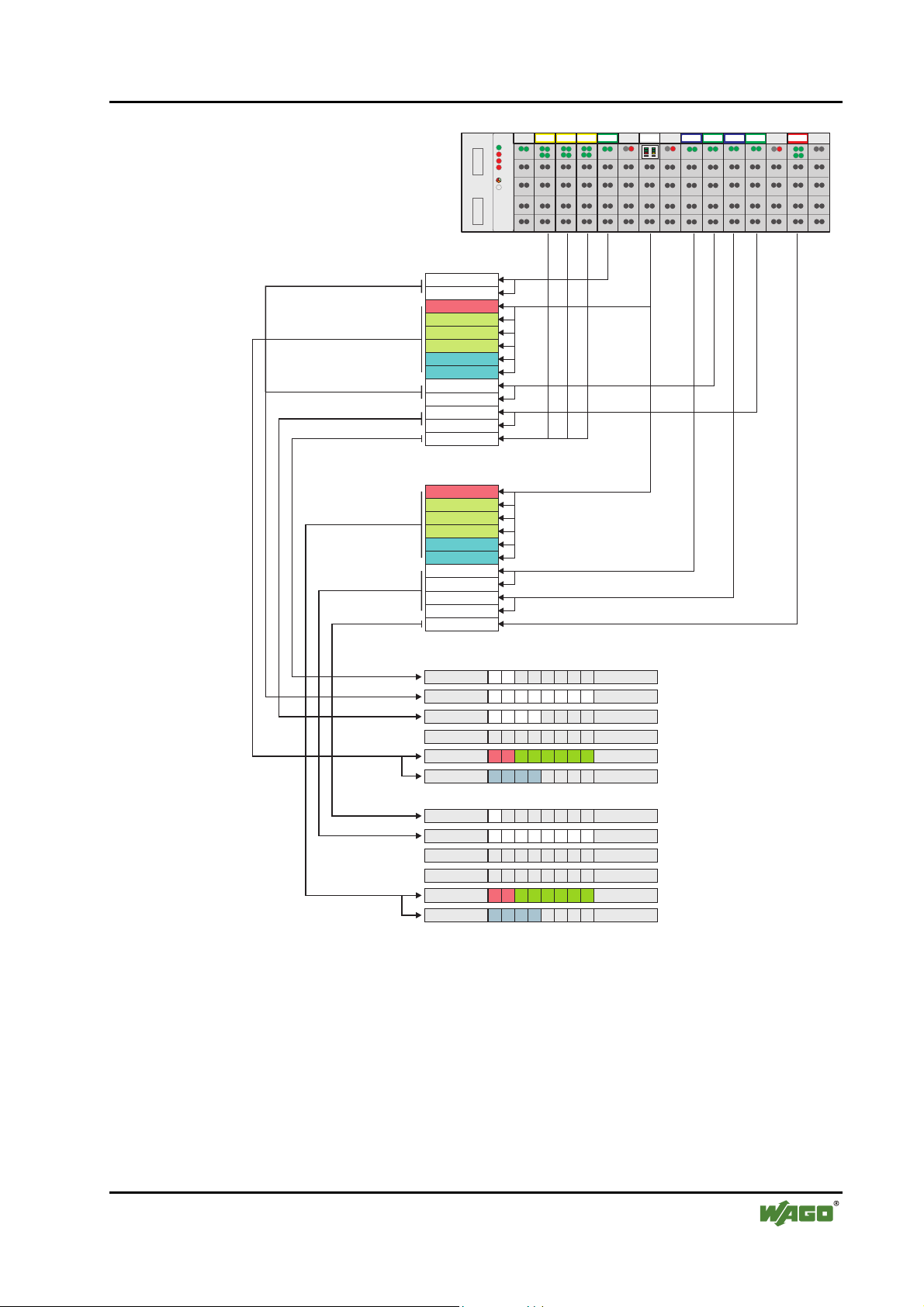
Fieldbus-specific Additions • 85
CANopen
1234 5678 910111213
DI DI
DI DI
DI DI
AI AI
BT
AO AO
AI AI
AO AO AI AI DO DO
Input image
AI1 C1
AI1 2C
Status byte
Mailbox
Mailbox
Mailbox
Data
Data
AI2 1C
AI2 2C
AI3 1C
AI3 2C
DI1 1-DI3 4CC
Output image
Control byte
Mailbox
Mailbox
Mailbox
Data
Data
AO1 C1
AO1 C2
AO2 C1
AO2 C2
DO1 C1-C4
750-337
452
402
402 402
644
602
602
452
504
602
452
600550 550
TxPDO 1, DI1 C1 - DI3 C4
TxPDO 2, AI1 C1 - AI2 C2
TxPDO 3, AI3 C1 - C2
TxPDO 4, not used
TxPDO 5, Status byte + Mailbox
TxPDO 6, Data byte1-4
RxPDO 1, DO1 C1 - C4
RxPDO 2, AO1 C1 - AO2 C2
RxPDO 3, not used
RxPDO 4, not used
RxPDO 5, Control byte + Mailbox
RxPDO 6, Data byte1-4
Figure 37: PDO allocation of a Bluetooth® module g064469e
WAGO-I/O-SYSTEM 750
I/O Modules
Page 86

86 • Fieldbus-specific Additions
DeviceNet
5.2 DeviceNet
5.2.1 Process Image Access
The DeviceNet master can access the Bluetooth® data in two ways.
With predefined instances of the assembly object, digital and analog input and
output data of a node are transmitted with a command to, or from, the master.
The application in the master can then address the data in the memory. The
data is stored in the master as it is for mapping in the coupler/controller. The
byte-oriented module data (analog modules and special modules) and the bitoriented module data (digital modules) are separated according to input and
output image in the memory in "arrays of byte". Therefore, the corresponding
array and associated memory address can be determined from module type.
The data in the Bluetooth® module can be directly addressed with the analog
input point object or the analog output point object. The instance number of
the respective object is based on the position of the module in the node.
5.2.1.1 Example
A node contains the following modules with input and output process image:
3 x 750-402 for every 4 bits of input data,
1 x 750-452 4 bytes of input data,
1 x 750-644 12 bytes of input and 12 bytes of output data,
1 x 750-550 4 bytes of output data,
1 x 750-452 4 bytes of input data,
1 x 750-550 4 bytes of output data,
1 x 750-452 4 bytes of input data,
1 x 750-504 4 bits of output data.
The Bluetooth® module uses a process image of 12 bytes with a mailbox size
of 6 bytes. The mailbox is unmasked.
WAGO-I/O-SYSTEM 750
I/O Modules
Page 87

Fieldbus-specific Additions • 87
DeviceNet
1234 5678 910111213
DI DI
DI DI
DI DI
AI AI
BT
AO AO
AI AI
AO AO AI AI DO DO
750-306
402
402 402
452
644
602
602
452
504
602
452
600550 550
Input image (in words)
Channel 1
Channel 2
Status
Mailbox
Assembly Object
Instance 9
Analog input data
Mailbox
Mailbox
Data
Data
Channel 1
Channel 2
Assembly Object
Instance 8
Digital input data
Channel 1
Channel 2
DI 1-12
Output image (in words)
Control
Mailbox
Mailbox
Assembly Object
Instance 3
Analog output data
Mailbox
Data
Data
Channel 1
Channel 2
Assembly Object
Instance 2
Digital output data
Channel 1
Channel 2
DO 1-4
Analog input data (in bytes)
Array of Byte
Channel 1
Channel 2
Status
Mailbox
Mailbox
Mailbox
Data
Data
Channel 1
Channel 2
Channel 1
Channel 2
Analog output data (in bytes)
Array of Byte
Control
Mailbox
Mailbox
Mailbox
Data
Digital input data
Array of Byte
DI 1-12
Data
Channel 1
Channel 2
Channel 1
Channel 2
Digital output data
Array of Byte
DO 1-4
Figure 38: Array allocation of a Bluetooth® module g064470e
WAGO-I/O-SYSTEM 750
I/O Modules
Page 88

88 • Fieldbus-specific Additions
ETHERNET
5.3 ETHERNET
5.3.1 Process Image Access
5.3.1.1 MODBUS Protocol
Bluetooth® module data is accessed with functions for reading and writing reg-
isters. Registers can be read and written in block or individually. A register includes two bytes.
The allocation of the register to the input and output data of the module is dependent on the order and type of modules.
Separated according to input and output data, the registers are first written in
ascending order with the data of the byte-oriented modules (analog and special
modules) and then with the data of the bit-oriented modules (digital modules).
The first input or output register allocated to a Bluetooth® module contains the
status or control byte and an empty byte.
Connected to this are the registers for the unmasked mailbox.
If the mailbox is set to be superimposable, these registers contain mailbox or
process data. Furthermore, registers allocated to a Bluetooth® module contain
the remaining process data.
In access by blocks, the data is transmitted with a command (e.g., FC 3 – Read
Multiple Registers, FC 16 – Write Multiple Registers or FC 23 – Read/Write
Multiple Registers). In the function call up, the start address and the number
of registers to be transmitted are given. Access to the individual data then occurs in the superordinate control.
The command FC 6 (Write Single Register) or the commands named above
are used for direct access to individual registers by setting the number of registers to be transmitted to one.
5.3.1.1.1 Example
A node contains the following modules with input and output process image:
3 x 750-402 for every 4 bits of input data,
1 x 750-452 4 bytes of input data,
1 x 750-644 12 bytes of input and 12 bytes of output data,
1 x 750-550 4 bytes of output data,
1 x 750-452 4 bytes of input data,
1 x 750-550 4 bytes of output data,
1 x 750-452 4 bytes of input data,
1 x 750-504 4 bits of output data.
The Bluetooth® module uses a process image of 12 bytes with a mailbox size
of 6 bytes. The mailbox is unmasked.
WAGO-I/O-SYSTEM 750
I/O Modules
Page 89

Fieldbus-specific Additions • 89
ETHERNET
1234 5678 910111213
DI DI
DI DI
DI DI
AI AI
BT
AO AO
AI AI
AO AO AI AI DO DO
750-342
402
402 402
452
644
602
602
452
504
602
452
600550 550
Input register
0
1
2
3
4
5
6
7
8
9
10
11
12
Output register
0
1
2
3
4
5
6
7
8
9
10
Status
Mailbox
Mailbox
Mailbox
Data
Data
Control
Mailbox
Mailbox
Mailbox
Data
Data
Access to data with FC 3,
Start address 2, Length 6
Access to data with FC 16,
Start address 0, Length 6
Figure 39: Register allocation of a Bluetooth® module g064471e
The input data of the Bluetooth® module is mapped to input registers 2
through 7. Register 2 contains the status byte and an empty byte. Register 3
through 5 contain the mailbox data. Register 6 and 7 contain the process data.
The data can be read with FC 3 (start address 2, length 6.
The output data is mapped to output register 0 through 5. Register 0 contains
the control byte and an empty byte. Registers 1 through 3 contain the mailbox
data. Register 4 and 5 contain the process data.
The data can be written with FC 16 (start address 0, length 6).
WAGO-I/O-SYSTEM 750
I/O Modules
Page 90

90 • Fieldbus-specific Additions
ETHERNET
5.3.1.2 EtherNet/IP Protocol
With the EtherNet/IP protocol, Bluetooth® data can be accessed in two ways.
In predefined instances of the assembly object, digital and analog input and
output data of a node are transmitted with a command to, or from, the Blue-
tooth® module. The application in the Bluetooth® module can then address the
data in the memory. The data is stored in the module in the same manner as
when mapping in the coupler/controller. The byte-oriented module data (analog modules and special modules) and the bit-oriented module data (digital
modules) are stored in the memory separately according to input and output
image. The memory address can then be determined from the type of module
and its position.
The data in the Bluetooth® module can be directly addressed with the analog
input point object or the analog output point object. The instance number of
the respective object is based on the position of the module in the node.
5.3.1.2.1 Example
A node contains the following modules with input and output process image:
3 x 750-402 for every 4 bits of input data,
1 x 750-452 4 bytes of input data,
1 x 750-644 12 bytes of input and 12 bytes of output data,
1 x 750-550 4 bytes of output data,
1 x 750-452 4 bytes of input data,
1 x 750-550 4 bytes of output data,
1 x 750-452 4 bytes of input data,
1 x 750-504 4 bits of output data.
The Bluetooth® module uses a process image of 12 bytes with a mailbox size
of 6 bytes. The mailbox is unmasked.
WAGO-I/O-SYSTEM 750
I/O Modules
Page 91

Fieldbus-specific Additions • 91
ETHERNET
1234 5678 910111213
DI DI
DI DI
DI DI
AI AI
BT
AO AO
AI AI
AO AO AI AI DO DO
750-341
402
402 402
644
452
602
602
452
504
602
452
600550 550
Input image
Channel 1
Channel 2
Status
Mailbox
Assembly Object
Instance 109
Analog input data
Mailbox
Mailbox
Data
Data
Channel 1
Channel 2
Assembly Object
Instance 108
Digital input data
Channel 1
Channel 2
DI 1-12
Output image
Control
Mailbox
Mailbox
Assembly Object
Instance 103
Analog output data
Mailbox
Data
Data
Channel 1
Channel 2
Assembly Object
Instance 102
Digital input data
Channel 1
Channel 2
DO 1-4
Analog Input data
Array of Byte
Channel 1
Channel 2
Status
Mailbox
Mailbox
Mailbox
Data
Data
Channel 1
Channel 2
Channel 1
Channel 2
Analog output data
Array of Byte
Control
Mailbox
Mailbox
Mailbox
Data
Digital input data
Array of Byte
DI 1-12
Data
Channel 1
Channel 2
Channel 1
Channel 2
Digital output data
Array of Byte
DO 1-4
Figure 40: Array allocation Bluetooth® module g065572e
WAGO-I/O-SYSTEM 750
I/O Modules
Page 92

92 • Fieldbus-specific Additions
PROFIBUS-DP
5.4 PROFIBUS-DP
5.4.1 Process Image Access
The Bluetooth® module data is accessed through the process image of the
PROFIBUS master. To ensure data consistency at a data width of 12 to 48
bytes, the data must be mapped with system functions for the consistent reading and writing to an appropriately large, reserved flag area. The data in this
flag area can then be processed by the control program.
5.4.1.1 Example
A node contains the following modules with input and output process image:
3 x 750-402 for every 4 bits of input data,
1 x 750-452 4 bytes of input data,
1 x 750-644 12 bytes of input and 12 bytes of output data,
1 x 750-550 4 bytes of output data,
1 x 750-452 4 bytes of input data,
1 x 750-550 4 bytes of output data,
1 x 750-452 4 bytes of input data,
1 x 750-504 4 bits of output data.
The Bluetooth® module uses a process image of 12 bytes with a mailbox size
of 6 bytes. The mailbox is unmasked.
The input/output configuration in the PROFIBUS master can be structured as
follows:
no. Function Module Process image of the master *
Identifier inputs outputs
1
2
3
Digital input EB12.0
Digital input EB12.1
Digital input EB12.2
Digital input
Digital input EB12.4
Digital input EB12.5
Digital input EB12.6
Digital input
Digital input EB13.0
Digital input EB13.1
Digital input EB13.2
Digital input
750-402 4 DI/24 V DC/3.0 ms
0x10
EB12.3
*750-402 4 DI/24 V DC/3.0 ms
0x00
EB12.7
750-402 4 DI/24 V DC/3.0 ms
0x10
EB13.3
WAGO-I/O-SYSTEM 750
I/O Modules
Page 93

Fieldbus-specific Additions • 93
PROFIBUS-DP
no. Function Module Process image of the master *
Identifier inputs outputs
Analog input EW 0 - 4
Analog input
5 Potential input Potential input - -
6
7 Potential input Potential input - -
12 Potential input Potential input - -
13
14 End Module End Module - -
Control/status byte EW 20 AW 10
Mailbox EW 22 AW 12
Mailbox EW 24 AW 14
Mailbox EW 26 AW 16
Data EW 28 AW 18
Data
Analog output - AW 0 8
Analog output
Analog input EW 4 - 9
Analog input
Analog output - AW 4 10
Analog output
Analog input EW 8 - 11
Analog input
Digital output - AB8.0
Digital output - AB8.1
Digital output - AB8.2
Digital output
750-452 2 AI/0…20 mA/diff.
0x51
750-644 Bluetooth® RF Trans-
ceiver
12 byte process image
0x8B
750-550 2 AO/0…10 V
0x61
750-452 2 AI/0…20 mA/diff.
0x51
750-550 2 AO/0…10 V
0x61
750-452 2 AI/0…20 mA/diff.
0x51
750-504 4 DO/24 V DC/0.5 A
0x20
EW 2 -
EW 30 AW 20
- AW 2
EW 6 -
- AW 6
EW 10 -
- AB8.3
* The addresses stated in the table correspond to the process data allocation given in the
configuration.
If the PROFIBUS master is a Siemens S7 SPS, the data is consistently read
and written with the system functions SFC14 and SFC15.
To map the input data EW20 through EW30 to the flag area MW100 through
MW110, the functions are accessed as follows:
CALL SFC 14
LADDR := W#16#14 (read from input address EW20)
RECORD := P#M100.0 BYTE 12 (write 12 bytes beginning with MW100)
RET_VAL := MW112 (write error messages after MW112)
To map the output data AW10 through AW20 to the flag area MW114
through MW124, the functions are accessed as follows:
WAGO-I/O-SYSTEM 750
I/O Modules
Page 94

94 • Fieldbus-specific Additions
PROFIBUS-DP
CALL SFC 15
LADDR := W#16#0A (write from output address AW10)
RECORD := P#M114.0 BYTE 12 (read 12 bytes beginning with MW114)
RET_VAL := MW126 (write error messages after MW126)
1234 5678 910111213
DI DI
DI DI
DI DI
AI AI
BT
AO AO
AI AI
AO AO AI AI DO DO
750-333
402
Input image
AI1 C1
AI1 2C
Status
Mailbox
Mailbox
Mailbox
Data
Data
AI2 1C
AI2 2C
AI3 1C
AI3 2C
DI1 1-DI3 4CC
Output image
Control
Mailbox
Mailbox
Mailbox
Data
Data
AO1 C1
AO1 C2
AO2 C1
AO2 C2
DO1 C1-C4
Process image of the PROFIBUS master
IW0
IW2
IW4
IW6
IW8
IW10
IW12
IW20
IW22
IW24
IW26
IW28
IW30
QW0
QW2
QW4
QW6
QW8
QW10
QW12
QW14
QW16
QW18
QW20
CALL SFC 14
LADDR := W#16#14
RECORD := P# M100.0 BYTE 12
RET_VAL := MW112
CALL SFC 15
LADDR := W#16#0A
RECORD := P# M114.0 BYTE 12
RET_VAL := MW126
402 402
452
644
602
602
452
MW100
MW102
MW104
MW106
MW108
MW110
MW112
MW114
MW116
MW118
MW120
MW122
MW124
MW126
504
602
452
600550 550
Figure 41: Process image allocation of a Bluetooth® module g064473e
WAGO-I/O-SYSTEM 750
I/O Modules
Page 95

Fieldbus-specific Additions • 95
LON
5.5 LON
The Bluetooth® module 750-644 is supported by the LON Fieldbus Coupler
750-319 and by the programmable LON Fieldbus Controller 750-819.
WAGO-I/O-SYSTEM 750
I/O Modules
Page 96

96 • Appendix
Mailbox Commands
6 Appendix
6.1 Mailbox Commands
This appendix provides an overview of all available mailbox commands,
sorted according to groups and opcodes (see Appendix 6.1.1) and according to
mailbox commands (see Appendix 6.1.2).
Which commands can be executed with which mailbox size is indicated by
symbols as follows:
●
Available
The command can be executed.
(●)
Available to a limited extent
Execution of the command is possible, but only as much
data as is possible for the current mailbox size is returned.
-
Not available
The command cannot be executed.
6.1.1 Overview Sorted According to Groups and Opcodes
May be
Mailbox commands Opcode Description
General commands
IDLE 0x00 No job 2 2 ● ● ● 104
Block transfer
DLD_START 0x01 Start transfer 6 3 ● ● ● 105
DLD_CONT 0x02 Continue transfer 2/6/12/
DLD_END 0x03 End transfer 5 6 ● ● ● 109
Maintenance and firmware
Length
query
Length
response
6/12/18 ● ● ● 107
18
executed
with mailbox
6 12 18
Page
RebootHost 0x10 Warm start host 2 2 ● ● ● 111
FlashRebootHost 0x11 Backup configuration, warm start 2 2 ● ● ● 112
GetHostFwVersion 0x12 Read host firmware version 3 6 ● ● ● 113
GetBbFwVersion 0x13 Read baseband firmware version 2 6/12 (●) ● ● 115
Process image
SetRemotePiSize 0x32 Determine the size of a slot for
data transfer in the master process
image
WAGO-I/O-SYSTEM 750
I/O Modules
4 2 ● ● ●
116
Page 97

Appendix • 97
Mailbox Commands
May be
Mailbox commands Opcode Description
Length
query
Length
response
executed
with mailbox
Page
6 12 18
GetRemotePiMapping 0x33 Query the remote process image
3 6 ● ● ●
118
parameters within the master
process image
Device configuration
GetLocalDeviceName 0x40 Read device names 2 3…18 (●) (●) ● 120
SetLocalDeviceName 0x41 Set device names 3…18 2 (●) (●) ● 121
GetLocalMacID 0x42 Read MAC-ID 2 8 - ● ● 123
GetLocalIPAddress 0x43 Read IP address 2 6 ● ● ● 124
SetLocalIPAddress 0x44 Set IP address 6 2 ● ● ● 125
GetLocalSubnetMask 0x45 Read subnet mask 2 6 ● ● ● 126
SetLocalSubnetMask 0x46 Write subnet mask 6 2 ● ● ● 127
GetLocalDeviceClass 0x47 Read local WAGO device class 2 4 ● ● ● 128
SetLocalDeviceClass 0x48 Write CoD settings 4 2 ● ● ● 129
GetLocalOperationMode 0x49 Read operation mode 2 4 ● ● ● 130
SetLocalOperationMode 0x4A Set operation mode 2 4 ● ● ● 131
GetLocalEncryptionMode 0x4D Read encryption mode 2 3 ● ● ● 133
SetLocalEncryptionMode 0x4E Set encryption mode 3 2 ● ● ● 134
GetLocalAuthenticationMode 0x4F Read authentication mode 2 3 ● ● ● 135
SetLocalAuthenticationMode 0x50 Write authentication mode 2 2 ● ● ● 136
GetLocalPassphrase 0x51 Read local Bluetooth® password 2 7…18 - (●)(●) 138
SetLocalPassphrase 0x52 Write local Bluetooth® password 7…18 2 - (●)(●) 139
EraseLocalAuthentication 0x53 Delete authentication settings 2 2 ● ● ● 141
GetLocalDeviceConfigLen 0x54 Read length of the configuration 2 4 ● ● ● 142
GetLocalDeviceRole 0x55 Read device role 2 3 ● ● ● 143
SetLocalDeviceRole 0x56 Write device role 3 2 ● ● ● 144
SetFactorySettings 0x57 Rewrite factory settings 2 2 ● ● ● 145
Network
ScanRemoteDevices 0x80 Search for remote Bluetooth®
5 2 ● ● ● 146
device in the wireless network
GetRemoteDeviceMacID 0x81 Read MAC-ID of a remote Blue-
GetRemoteDeviceName 0x82 Read device name of a remote
®
device
tooth
Bluetooth
®
device
AllowRemoteDevice 0x83 Enter remote device in authoriza-
2 9 - ● ●
2 6…18 (●) (●)(●)
148
150
9 2 - ● ● 152
tion table
WAGO-I/O-SYSTEM 750
I/O Modules
Page 98

98 • Appendix
Mailbox Commands
May be
Mailbox commands Opcode Description
Length
query
Length
response
executed
with mailbox
Page
6 12 18
GetAllowedRemoteDevices 0x84 Read back remote device from
2 8 - ● ● 154
the authorization table
BindRemoteDevice 0x85 Activate authorized device 3 2 ● ● ● 156
UnbindRemoteDevice 0x86 Deactivate authorized device 3 2 ● ● ● 157
GetBoundRemoteDevices 0x87 Read access authorization for
2 3
● ● ● 159
remote devices
GetConnectionQoS 0x88 Read Quality-of-Service settings 2 3 ● ● ● 160
SetConnectionQoS 0x89 Set Quality-of-Service 4 2 ● ● ● 161
GetReconnectionTimePeriod 0x8A Read time between attempts to
2 4 ● ● ● 163
establish connection
SetReconnectionTimePeriod 0x8B Set time between attempts to
4 2 ● ● ● 164
establish connection
GetUserfriendlyName 0x8C Read user-friendly name for a
2 3…18 (●) (●) ● 166
slave entry
SetUserfriendlyName 0x8D Set user-friendly name to a slave
3…18 2 (●) (●) ● 168
entry
Diagnostics
GetLocalDeviceStatus 0xD0 Read status of the local bus
2 6 ● ● ● 170
module
GetNetworkStatus 0xD1 Read network status 2 4 ● ● ● 172
GetStatusMessage 0xD2 Read status reports 4 6 ● ● ● 174
GetLinkQuality 0xD5 Read connection quality 3 3 ● ● ● 179
GetLinkSignalStrength 0xD7 Read signal strength 3 3 ● ● ● 181
GetAvailableChannelMap 0xD8 Read available wireless channels 3 12 - ● ● 183
SetLED 0xD9 Test LED function 5
2
● ● ● 185
MirrorMailboxCommand 0xDA Mirror mailbox command for test 6/12/18 6/12/18 ● ● ● 187
GetLocalUpTime 0xDB Read operating time of the
6/8 6/8 (●) ● ● 188
module
WAGO-I/O-SYSTEM 750
I/O Modules
Page 99

Appendix • 99
Mailbox Commands
6.1.2 Overview Sorted According to Mailbox Commands
May be
Mailbox command Opcode Description
Length
query
Length
re-
sponse
executed
with mailbox
6 12 18
Page
AllowRemoteDevice 0x83 Enter remote device in authoriza-
9 2 - ● ● 152
tion table
BindRemoteDevice 0x85 Activate authorized device 3 2 ● ● ● 156
DLD_CONT 0x02 Continue transfer 2/6/12
/18
6/12
/18
● ● ● 107
DLD_END 0x03 End transfer 5 6 ● ● ● 109
DLD_START 0x01 Start transfer 6 3 ● ● ● 105
EraseLocalAuthentication 0x53 Delete authentication settings 2 2 ● ● ● 141
FlashRebootHost 0x11 Backup configuration, warm start 2 2 ● ● ● 112
GetAllowedRemoteDevices 0x84 Read back remote device from the
2 8 - ● ● 154
authorization table
GetAvailableChannelMap 0xD8 Read available wireless channels 3 14 - - ● 183
GetBbFwVersion 0x13 Read baseband firmware version 2 6/12 (●) ● ● 115
GetBoundRemoteDevices 0x87 Read access authorization for
2 3
● ● ● 159
remote devices
GetConnectionQoS 0x88 Read Quality-of-Service settings 2 3 ● ● ● 160
GetHostFwVersion 0x12 Read host firmware version 3 6 ● ● ● 113
GetLinkQuality 0xD5 Read connection quality 3 3 ● ● ● 179
GetLinkSignalStrength 0xD7 Read signal strength 3 3 ● ● ● 181
GetLocalAuthenticationMode 0x4F Read authentication mode 2 3 ● ● ● 135
GetLocalDeviceClass 0x47 Read local WAGO device class 2 4 ● ● ● 128
GetLocalDeviceConfigLen 0x54 Read length of the configuration 2 4 ● ● ● 142
GetLocalDeviceName 0x40 Read device names 2 3…18 (●) (●) ● 120
GetLocalDeviceRole 0x55 Read device role 2 3 ● ● ● 143
GetLocalDeviceStatus 0xD0 Read status of the local bus mod-
2 6 ● ● ● 170
ule
GetLocalEncryptionMode 0x4D Read encryption mode 2 3 ● ● ● 133
GetLocalIPAddress 0x43 Read IP address 2 6 ● ● ● 124
GetLocalMacID 0x42 Read MAC-ID 2 8 - ● ● 123
GetLocalOperationMode 0x49 Read operation mode 2 4 ● ● ● 130
GetLocalPassphrase 0x51 Read local Bluetooth® password 2 7…18 - (●)(●) 138
GetLocalSubnetMask 0x45 Read subnet mask 2 6 ● ● ● 126
GetLocalUpTime 0xDB Read operating time of the module 6/8 6/8 (●) ● ● 188
GetNetworkStatus 0xD1 Read network status 2 4 ● ● ● 172
WAGO-I/O-SYSTEM 750
I/O Modules
Page 100

100 • Appendix
Mailbox Commands
May be
Mailbox command Opcode Description
Length
query
Length
re-
sponse
executed
with mailbox
Page
6 12 18
GetReconnectionTimePeriod 0x8A Read time between attempts to
2 4 ● ● ● 163
establish connection
GetRemoteDeviceMacID 0x81 Read MAC-ID of a remote Blue-
GetRemoteDeviceName 0x82 Read device name of a remote
®
device
tooth
Bluetooth
®
device
GetRemotePiMapping 0x33 Query the remote process image
2 9 - ● ●
2 6…18 (●) (●) (●)
3 6 ● ● ●
148
150
118
parameters within the master process image
GetStatusMessage 0xD2 Read status reports 4 6 ● ● ● 174
GetUserfriendlyName 0x8C Read user-friendly name for a
2 3…18 (●) (●) ● 166
slave entry
IDLE 0x00 No job 2 2 ● ● ● 104
MirrorMailboxCommand 0xDA Mirror mailbox command for test 6/12
/18
6/12
/18
● ● ● 187
RebootHost 0x10 Warm start host 2 2 ● ● ● 111
ScanRemoteDevices 0x80 Search for remote Bluetooth®
5 2 ● ● ● 146
device in the wireless network
SetConnectionQoS 0x89 Set Quality-of-Service 4 2 ● ● ● 161
SetFactorySettings 0x57 Rewrite factory settings 2 2 ● ● ● 145
SetLED 0xD9 Test LED function 5
● ● ● 185
2
SetLocalAuthenticationMode 0x50 Write authentication mode 2 2 ● ● ● 136
SetLocalDeviceClass 0x48 Write CoD settings 4 2 ● ● ● 129
SetLocalDeviceName 0x41 Set device names 3…18 2 (●) (●) (●) 121
SetLocalDeviceRole 0x56 Write device role 3 2 ● ● ● 144
SetLocalEncryptionMode 0x4E Set encryption mode 3 2 ● ● ● 134
SetLocalIPAddress 0x44 Set IP address 6 2 ● ● ● 125
SetLocalOperationMode 0x4A Set operation mode 2 4 ● ● ● 131
SetLocalPassphrase 0x52 Read local Bluetooth® password 7…18 2 - (●) (●) 139
SetLocalSubnetMask 0x46 Write subnet mask 6 2 ● ● ● 127
SetReconnectionTimePeriod 0x8B Set time between attempts to es-
4 2 ● ● ● 164
tablish connection
SetRemotePiSize 0x32 Determine the size of a slot for
4 2 ● ● ●
116
data transfer in the master process
image
SetUserfriendlyName 0x8D Set user-friendly name to a slave
3…18 2 (●) (●) ● 168
entry
UnbindRemoteDevice 0x86 Deactivate authorized device 3 2 ● ● ● 157
WAGO-I/O-SYSTEM 750
I/O Modules
 Loading...