


lease
blox cellular
IoT Security-as-a-Service
SARA-R4 / SARA-R5
Application Note
Abstract:
Technical data sheet describing the IoT Security-as-a-Service value proposition for umodule series SARA-R4 and SARA-R5.
UBX-20013561 - R06
C1-Public www.u-blox.com

IoT Security-as-a-Service - Application Note
Prototype
Objective specification
Target values. Revised and supplementary data will be published later.
Advance information
Data based on early testing. Revised and supplementary data will be published later.
Early production information
Data from product verification. Revised and supplementary data may be published later.
u-blox or third parties may hold intellectual property rights in the products, names, logos and designs included in this document.
Copying, reproduction, modification or disclosure to third parties of this document or any part thereof is only permitted with the
express written permission of u
The information contained herein is provided “as is” and u
. No warranty, either express or
implied, is given, including but not limited
s, reliability and fitness for a particular
purpose of the information. This document may be revised by u
most recent documents,
visit www.u
Copyright © u
Document information
Title IoT Security-as-a-Service
Subtitle SARA-R4 / SARA-R5
Document type Application Note
Document number UBX-20013561
Revision and date R06 05-11-2020
Disclosure restriction
C1-Public
Product status
Functional Sample
In development /
Engineering sample
Initial production
Mass production /
End of life
Corresponding content status
Draft For functional testing. Revised and supplementary data will be published later.
Production information Document contains the final product specification.
This document applies to the following products:
Product name
SARA-R4 series
SARA-R5 series
"63" / "73" /”83B” product versions
All product versions
UBX-20013561 - R06 Document information Page 2 of 53
C1-Public
-blox.com.
-blox AG.
-blox.
-blox assumes no liability for its use
to, with respect to the accuracy, correctnes
-blox at any time without notice. For the

IoT Security-as-a-Service - Application Note
Contents
Document information ................................................................................................................................ 2
Contents .......................................................................................................................................................... 3
1 Introduction ............................................................................................................................................. 5
1.1 Important note ............................................................................................................................................ 5
1.2 Scope ............................................................................................................................................................. 5
2 Security ..................................................................................................................................................... 6
2.1 Overview ........................................................................................................................................................ 6
2.2 Foundations of u-blox security ................................................................................................................. 6
2.2.1 Secure boot .......................................................................................................................................... 7
2.2.2 Secure updates ................................................................................................................................... 7
2.2.3 Secure production .............................................................................................................................. 7
2.2.4 Root of trust ......................................................................................................................................... 7
3 Services APIs ........................................................................................................................................... 9
3.1 REST APIs security ..................................................................................................................................... 9
3.2 Accessing the REST APIs .......................................................................................................................... 9
3.3 How to access the u-blox IoT Security-as-a-Service when using a private network ...................10
4 Claim ownership .................................................................................................................................. 11
4.1 Automatic enrollment ..............................................................................................................................11
4.1.1 Change the ownership .....................................................................................................................13
4.2 Bootstrap and device assignment to the owner procedure .............................................................13
4.3 Two stage bootstraps ..............................................................................................................................14
4.4 Security heartbeat ....................................................................................................................................14
4.5 Feature provisioning .................................................................................................................................16
4.5.1 Service provisioning .........................................................................................................................16
4.6 Anti-cloning detection and rejection .....................................................................................................17
5 Design security .................................................................................................................................... 18
5.1 Local C2C (Chip-to-Chip) Security .........................................................................................................18
5.1.1 C2C encapsulation and encryption protocol ...............................................................................19
5.1.2 Local C2C key pairing .......................................................................................................................20
5.1.3 Local C2C usage (Open secure session) ......................................................................................23
5.1.4 Local C2C usage (Close secure session) ......................................................................................25
5.1.5 Local C2C Rekeying ..........................................................................................................................26
5.1.6 Local C2C use-case ..........................................................................................................................26
5.2 Local data protection ...............................................................................................................................27
5.2.1 Use case ..............................................................................................................................................28
6 E2E Security ......................................................................................................................................... 29
6.1 E2E Symmetric KMS ................................................................................................................................29
6.1.1 Use case ..............................................................................................................................................31
6.2 End-to-end data protection ....................................................................................................................36
6.2.1 Upstream (device to cloud) .............................................................................................................37
6.2.2 Downstream (cloud to device) ........................................................................................................38
6.2.3 Use case ..............................................................................................................................................39
6.3 TLS version .................................................................................................................................................42
UBX-20013561 - R06 Contents Page 3 of 53
C1-Public

IoT Security-as-a-Service - Application Note
6.4 DTLS version ..............................................................................................................................................42
7 Access control ..................................................................................................................................... 43
7.1 Zero Touch Provisioning ..........................................................................................................................43
7.1.1 Service registration ..........................................................................................................................43
7.1.2 Certificate provisioning ...................................................................................................................44
7.1.3 Just in time provisioning .................................................................................................................45
7.1.4 Device registration ...........................................................................................................................46
7.1.5 Use case (ZTP for Amazon Web Services) ..................................................................................46
Appendix ....................................................................................................................................................... 51
A Glossary ................................................................................................................................................. 51
Related documents ................................................................................................................................... 52
Revision history .......................................................................................................................................... 52
Contact .......................................................................................................................................................... 53
UBX-20013561 - R06 Contents Page 4 of 53
C1-Public

IoT Security-as-a-Service - Application Note
1 Introduction
1.1 Important note
⚠ To be read before reviewing any other part of this document
The main aspect of this document is to detail the exciting opportunities that customers will have to
manage and organize the services and firmware on their own devices. However, this functionality
cannot be utilized if the ownership of each device has not been correctly claimed by the customer.
Ownership can only be achieved by sealing a valid DeviceProfileUID into the customer’s devices.
DeviceProfileUID can be autonomously generated accessing to the personal account in the u-blox
Thingstream service management console. Moreover, in order to be authorized to use the IoT
Security-as-a-Service APIs you need to generate the access key and secret through the management
console.
☞ Before reading this document, look at the Getting started guide to have an overview about all the
initial steps required
The ownership process is described in more detail in section 4 below.
1.2 Scope
This document describes what is defined by the term “Security” and how it is implemented in u-blox
cellular modules. In the document, “security services” indicates IoT Security-as-a-Service solutions.
Section 2 provides an overview of security and its strengths and details about foundation security as
the base for all security services.
Section 3 provides details about the u-blox services APIs.
Section 4 describes claim ownership process.
Section 5 describes Design security.
Section 6 describes End-to-End security.
Section 7 describes Zero Touch Provisioning (ZTP).
UBX-20013561 - R06 Introduction Page 5 of 53
C1-Public

IoT Security-as-a-Service - Application Note
2 Security
2.1 Overview
For today’s cloud-based information technology environment, it is vital to secure all data from
unauthorized or fraudulent access. For IoT devices the security of data is vital to protect both
businesses and the individual user / person.
For example:
• In connected retail a POS terminal must protect revenue flow from fraud by:
o Securely controlling access to the payment terminal.
o By providing payment data to authorized parties only.
• In asset tracking the data must be authenticated to the correct device to ensure the integrity of
the business process and its control.
• In order to protect recurring service revenues, smart devices in buildings must ensure that only
authorized technicians can remotely access and troubleshoot building management functions.
IoT devices connect physical objects to provide data traffic and access to networks – however the
physical objects (i.e. medical devices, controls, utility meters, vehicles, etc.) and the network of things
must also be secured. A weak element in IoT security (also known as a defect or vulnerability) may
ultimately also become a safety issue.
The u-blox device security implementation is designed to entirely remove these weak elements and
prevent the unauthorized or fraudulent access to the underlying data.
The following definitions will help in understanding the fundamentals of security:
• Integrity ensures that pieces of data have not been altered from a reference or controlled version.
• Authentication ensures that a given entity (with which the user is interacting) is the expected one.
• Authenticity is a special type of integrity, where the reference or controlled version is defined as
exactly the state of the data when it was under the control of a specific entity.
• Confidentiality means that no unauthorized access to the data is allowed (that is, encryption or
cryptography will be used).
2.2 Foundations of u-blox security
The strengths of the u-blox security service include the following:
• Unique device identity: An immutable chip ID together with a robust root of trust provide the
foundational security.
• Secure boot sequence and update processes: Only authenticated and authorized firmware and
updates can run on the device.
• Hardware-backed crypto functions: A secure client library generates the keys and cryptographic
functions to securely connect to the cloud.
• Root of trust-based authentication: Using the protected root of trust and unique session keys
ensures the integrity and confidentiality of both the communications and the data-at-rest (i.e.
inactive data that is stored physically in any digital form).
The following features maintain the integrity of the device over its entire lifecycle.
UBX-20013561 - R06 Security Page 6 of 53
C1-Public

IoT Security-as-a-Service - Application Note
2.2.1 Secure boot
Secure boot maintains the integrity of the code running on the module to ensure the device only runs
trusted software issued by an authorized manufacturer.
Because the authenticity and integrity of the software is secured, the module is suitable to be used in
mission critical solutions and enables highly secured devices.
2.2.2 Secure updates
Secure updates performed via FOTA or uFOTA (see the FW update application note [5]) allow the
customer’s chosen FOTA platform to remotely and securely update the module’s firmware. Updates
are signed by u-blox and verified before being applied. The resulting updated firmware is then
authenticated in the module via the secure boot process.
uFOTA is a comprehensive end-to-end u-blox FOTA service that allows customers control of the
process for remotely updating the module’s firmware “over-the-air”. This process utilizes the
additional security provided between the module and the service via PSK provisioning.
uFOTA enables the updating of the module firmware at no extra data overhead and cost of
implementing such services and processes, since they are implemented by u-blox.
☞ Customer permission is always required before any updates are performed.
2.2.3 Secure production
Secure production is undertaken with a significant emphasis on security, using well designed
processes and methods. The root of trust (RoT) is securely provisioned with personalization data
(using several keys). The personalization data is delivered using multiple layers of encryption to
protect it during the end-to-end process. Each layer of encryption is only retrieved at the correct stage
in the process, with the final layer only being retrieved within the module RoT itself.
As mentioned, the benefit for customers is that the module can be used in mission critical solutions
and enables highly secured devices.
☞ u-blox provisions secrets into each SARA-R4 module during the production process.
SARA-R5 products integrate a secure element in which secrets are provisioned by the secure element
chip manufacturer before the u-blox production process.
2.2.4 Root of trust
The root of trust (RoT) can always be trusted within a cryptographic system by providing a
comprehensive set of advanced security tools including:
• The secure execution of user applications.
• Tamper detection and protection.
• Secure storage and handling of keys and security assets.
• Resistance to side-channel attacks.
In SARA-R4 products the RoT is implemented in a trusted execution environment (TEE) and is a
critical component of the system.
A TEE is a secure area inside the main processor (trusted OS area), which is physically separated from
the rich OS (rich execution environment, REE) where applications are running. It protects the
confidentiality and integrity of the code and the data loaded into the TEE. It provides an excellent level
of robustness that is sufficient for the majority of IoT applications. A RoT implemented in the TEE
provides a better level of robustness compared to classic systems, which only implement security in
the REE.
UBX-20013561 - R06 Security Page 7 of 53
C1-Public

IoT Security-as-a-Service - Application Note
In SARA-R5 products the RoT is integrated in a secure element (SE).
A secure element is a dedicated microprocessor chip which stores sensitive data and runs secure
applications. It acts as a vault, protecting what’s inside the SE (applications and data) from malware
attacks that are typical in the host (i.e., the device operating system). This secure element is Common
Criteria certified EAL5+ and it allows to have eUICC on SARA-R5 since the GSMA and mobile network
operators require at least EAL4 to host an eSIM.
☞ SARA-R4 "63B", “73B”,”83B” product versions implement the RoT in the TEE.
☞ SARA-R5 products implement the RoT in the SE.
Figure 1: Security robustness levels
The IoT device is secured using the following steps:
• Provision trust – insert the root of trust at production: An immutable chip ID and the
hardware-based root of trust inserted during the production process provide the foundational
security and a unique device identity.
• Leverage trust – derive the trusted keys: Secure libraries and hardware-supported crypto
functions allow the generation of keys that securely connect the device to the cloud.
• Guarantee trust – use secure keys to secure any function: Secure keys ensure the authenticity,
integrity, and confidentiality to maintain control of the device and the data.
UBX-20013561 - R06 Security Page 8 of 53
C1-Public

IoT Security-as-a-Service - Application Note
3 Services APIs
The u-blox IoT Security-as-a-Service APIs provide cloud services to customers from where they can
access and manage the security features and processes for their devices, along with any other
functionality described in this document.
The REST APIs are defined and fully documented in the separate on-line documentation available at
“https://api.services.u-blox.com”. The swagger (YAML) specification file can be downloaded from the
same webpage.
If not yet done, we strongly recommend users to read the Getting started guide
3.1 REST APIs security
The APIs are secured using an API key and secret which can be generated on the u-blox Thingstream
services portal. The secret is used to generate an authorization header, which is used to authorize the
requests made to u-blox (see sections 6.1.1 and 6.2.3).
For further details on how to generate the authorization header, see the swagger documentation at
https://api.services.u-blox.com.
3.2 Accessing the REST APIs
To manage the IoT Security-as-a-Service, customers must first subscribe to an account for the u-blox
Thingstream, which is the service and account management platform for IoT Security-as-a-Service.
You can select between
• Basic account: an IoT Security-as-a-Service free-of-charge account restricted to up to ten active
devices
• Enterprise or Pro account: for more than 10 active devices; this is required to enable the
commercial version and to access to advanced features
Once access to the APIs has been granted, the customer will be able to view and manage the IoT
Security-as-a-Service attributes on their devices.
The APIs can be used to manage the following:
• Claim of ownership of individual devices as part of the bootstrap process (see section 4)
• Service provisioning and IoT Security-as-a-Service management functionality (see section 4.5)
including the management of:
o Individual devices
o The security services that are enabled / disabled on each device
o The device profiles used to identify devices and owners
o The process to organize global updates of multiple devices to enable or disable the security
services on them
The Sequence diagram in Figure 2 shows the API access process including:
• Customer onboarding
• Service account creation
• API key and secret retrieval
• Refresh Auth token
• Call APIs
UBX-20013561 - R06 Services APIs Page 9 of 53
C1-Public

IoT Security-as-a-Service - Application Note
Figure 2: API access processes
3.3 How to access the u-blox IoT Security-as-a-Service when
using a private network
To ensure the security services processes will work, customers using a private network (private APN)
must first check that their devices can reach the u-blox security service.
In particular, check that the module is able to connect to the domain icpp.services.u-blox.com.
If the module cannot reach the domain icpp.services.u-blox.com, the IPv4/IPv6 addresses may need
to be whitelisted on the private APN server in order to allow the connection to be made.
UBX-20013561 - R06 Services APIs Page 10 of 53
C1-Public

IoT Security-as-a-Service - Application Note
AT+USECDEVINFO="DeviceProfileUID","serial"
OK
u-blox
services portal
Device registration request
(brand mod el, HW revision….)
Device
Module
Device software
AT commands
Device profile UID (mandatory)
Device serial number (manda tory)
Customer –provisioned data
(optio nal)
DeviceProfileUID
Device maker
1
2
3
u-blox
software
RoT
4
4 Claim ownership
4.1 Automatic enrollment
Ownership can only be achieved by sealing a valid DeviceProfileUID into the customer’s devices. Once
customers have a service account, they can use the APIs to request a DeviceProfileUID and seal it in
their devices accordingly.
Secrets are provisioned into each module during the production process (the secrets are unique to
each module and are identified by the RoT public unique identifier - RoTPublicUID).
To claim ownership of individual devices, customers must first create a DeviceProfileUID using the
u-blox Thingstream Service management console.
The device profile unique identifier – DeviceProfileUID is equivalent to a model number and can be
used to identify a group of similar devices that need to have the same set of Security features enabled
at bootstrap.
Customers must then store the DeviceProfileUID into each device within the same group (normally
this is all the devices with the same type number). This is completed (either in their host firmware, e.g.
on device startup, or on their production line) by using the AT+USECDEVINFO AT command, along
with their own device serial number (this unique number for the device will be defined by the
customer).
☞ With the AT command you seal the DeviceProfileUID and the device serial number into the RoT;
they cannot be changed once they have been set – any subsequent calls to this AT command are
ignored. Please be careful on sealing the correct DeviceProfileUID generated through the u-blox
Thingstream platform.
Command
☞ Please note you can just do sealing procedure (via AT+USECDEVINFO) once and any future retry
will be ignored by the device.
Response Description
Seal the DeviceProfileUID and the device serial
number into the module.
Figure 3: Process to set DeviceProfileUID and device serial number
UBX-20013561 - R06 Claim ownership Page 11 of 53
C1-Public

IoT Security-as-a-Service - Application Note
Figure 4: Automatic enrollment of device process
Device profile unique identifiers (DeviceProfileUID) shall be used by the customer to “label” and claim
ownership of each device:
• Assign the DeviceProfileUID to the module using the +USECDEVINFO AT command
• Bootstrap the device in order to link it to the matching DeviceProfileUID created by u-blox
Once a device bootstraps, the system will recognize the DeviceProfileUID and assign ownership of the
device to the correct customer account (the company). It is then possible to configure the device
further using the functionality available in the u-blox services APIs.
The basic process for the customer to claim ownership of a device is:
1. Create the Device Profile UID.
2. Seal each DeviceProfileUID into the correct device(s).
3. Connect each device to the Internet.
4. Wait for each device to register to security services (monitor the status via AT+USECDEVINFO?
query).
5. The device should now be assigned into customer’s account and the device registration date
should be set.
UBX-20013561 - R06 Claim ownership Page 12 of 53
C1-Public

IoT Security-as-a-Service - Application Note
AT+USECDEVINFO?
Command
Response
Description
AT+USECDEVINFO?
+USECDEVINFO: 0,0,0
+USECDEVINFO: 1,0,1
+USECDEVINFO: 1,1,1
☞ Customers can enable IoT Security-as-a-Service on device(s) when they bootstrap. This option
removes the need to create similar campaigns once the bootstrap has been successful and means
the required IoT Security-as-a-Service features are immediately available following a successful
bootstrap.
4.1.1 Change the ownership
You have the possibility to change the ownership of a single device or a group of devices. There are
procedures in the u-blox back-end to handle it for you. Just write to services support (
support@u-blox.com)
•
DeviceProfileUID of the device(s) that the ownership should be changed
Current owner thingstream domain name
•
Future owner thingstream domain name
•
and please provide the following information:
thingstream-
4.2 Bootstrap and device assignment to the owner procedure
1. The module bootstraps to the u-blox security server (icpp.services.u-blox.com) when the actual
device first connects to the internet. The bootstrap process happens only once; if subsequent
power cycles occur, then the device is recognized as already being bootstrapped.
2. The process replaces the factory-provisioned secrets and adds the necessary keys to enable the
relevant features/services.
3. During bootstrap the device becomes associated with its registered owner (via the
DeviceProfileUID that was created) and any cloned devices are rejected.
4. The customer now has ownership of the device.
⚠ During the initial bootstrap it is recommended that the application does not try to reset or power
The bootstrap process requires 4 individual communication phases over which at least 1048 bytes
are transferred. The maximum amount of data that can be transferred will vary and can depend on:
1. Whether “Feature authorizations” data must be sent.
2. Whether retransmissions must be done because an original attempt failed.
3. Whether Internet Protocol version 4 (IPv4) or version 6 (IPv6) is being used.
The +USECDEVINFO can be called to confirm that the bootstrap attempt has either not yet finished
(that is, the current attempt was not successful, and another attempt will be tried) or the bootstrap
process has been successful.
Command
The response to the AT+USECDEVINFO? Query has the following meaning:
cycle the module until the process is completed successfully. The time needed to conclude the
process is strictly dependent on the RAT being used. If the bootstrap process is interrupted before
completion, the process will re-start from the beginning.
Description
Check bootstrap status.
The module is not able to reach the u-blox security service. No
bootstrap can be performed. Check that data connection is
available and a suitable APN has been set.
The module is registered to the u-blox security service and
bootstrap has started. Device has not been sealed with a
DeviceProfileUID yet.
OK
The module is registered to the u-blox security service and
bootstrap is complete.
UBX-20013561 - R06 Claim ownership Page 13 of 53
C1-Public

IoT Security-as-a-Service - Application Note
Device maker
(owner of Device
Profile UIDs)
Device
Module
u-blox
software
Device software
User can see device in the
portal
Device registration
Claim of ownership
Bootstrap message (RoT public UID,
bootstrap data)
u-blox services portal
Module Ro Tauthentication
Anti-cloning checks
Activation notification
Keys refresh, sec urity policies, features
authorization
Device activation
(RoT public UI D, Device Pr ofile UID, e tc.)
RoT
1
2
3
4
Command
AT+USECCONN
OK
If the bootstrap process is still in progress (that is, it has not finished or been successful or an error
condition has occurred), then the AT command will return an error.
☞ In SARA-R4 products, if the bootstrap process is still in progress, AT+USECDEVINFO? Will block
until the operation is complete.
☞ To prevent flooding the server with security heartbeat messages, if the command is issued within
Figure 5: Device bootstrap process
4.3 Two stage bootstraps
In some circumstances the bootstrapping of one or more devices may need to be completed in two
stages (two-stage bootstrap).
This is the scenario when the bootstrap happens when the DeviceProfileUID has not already been
sealed in the device. The device is registered but cannot be assigned to the correct customer.
When, at a later stage, the DeviceProfileUID is sealed in the device, it communicates with the u-blox
server and it is therefore assigned to the correct customer. The customer can then manage the device
using the u-blox Thingstream Management console or the APIs.
4.4 Security heartbeat
Once a device has successfully bootstrapped, it will continue to call the u-blox security service on a
regular basis: this is known as a “security heartbeat”.
By default, the security heartbeat occurs automatically once a week. It is possible, though, to trigger
a security heartbeat from the module by using the AT+USECCONN command:
Response Description
5 minutes of the last sent security heartbeat, the request will be rejected, and an error result code
will be returned.
Trigger a security heartbeat to the u-blox security service.
UBX-20013561 - R06 Claim ownership Page 14 of 53
C1-Public

IoT Security-as-a-Service - Application Note
Figure 6: Enrollment of devices with security heartbeat
4.4.1.1 Security heartbeats on SARA-R4
To prevent flooding the server with "security heartbeats", if the command is issued within 5 minutes
of the last sent "security heartbeat", the request will be rejected, and an error result code will be
returned. The system time is used for measuring elapsed time. When a "security heartbeat" is sent,
the system time is stored in NVM, therefore the value is persistent to power cycles. When an attempt
to send a "security heartbeat" occurs, the previous send time is checked against the current system
time, to see if the elapsed time is valid.
UBX-20013561 - R06 Claim ownership Page 15 of 53
C1-Public

IoT Security-as-a-Service - Application Note
4.4.1.2 Security heartbeats on SARA-R5
• The "security heartbeat" message operation is required to update the status of the security.
• The "security heartbeat" message operation is for security reasons required to be an atomic
message operation using a blocking send/receive cycle.
• The blocking send/receive cycle can execute up to 5 minutes (before timeout and abort) in case of
network issues.
• The blocking send/receive cycle can block (up to 5 minutes) the execution of the command
(affected commands listed below) which triggered the "security heartbeat" message operation.
• The "security heartbeat" message operation before executing the blocking send/receive cycle
verifies if the "security heartbeat" message shall be sent immediately due to security reasons.
• The "security heartbeat" message operation before executing the blocking send/receive cycle
verifies if the "security heartbeat" message shall be sent immediately due to server configured
time period elapsed.
To prevent flooding the server with "security heartbeats", if the command is issued within 24 hours of
the last sent "security heartbeat", the request will be rejected, and an error result code will be returned.
The system time is used for measuring elapsed time. When a "security heartbeat" is sent, the system
time is stored in NVM; therefore, the value is persistent to power cycles. When an attempt to send a
"security heartbeat" occurs, the previous send time is checked against the current system time, to
see if the elapsed time is valid.
4.5 Feature provisioning
Customers can activate/deactivate a feature in two ways:
• At device profile level: when the device profile is created using the Management Console. In this
case all devices that makes the bootstrap with that DeviceProfileUID, will get activated the
selected features. Be aware that if you change the Device profile definition at a later stage (i.e.
deactivating a feature previously enabled), this change will be applicable only to the devices that
make bootstrap from that time.
• At device level: on each active device you can activate/deactivate a feature at any time using the
Management console or the APIs
Activation/deactivation on the device happens at the next Security Heartbeat event after that you
have applied the new setting. You can monitor the status both from the API and the Management
console.
You can always trigger the Security Heartbeat as described in section 4.4
Feature provisioning is applicable to:
• Local Data Protection
• Local Chip-to-Chip Security
• Zero Touch Provisioning
4.5.1 Service provisioning
Symmetric KMS (PSK) and E2E data protection services are automatically provisioned during the
bootstrap process when the customer selects a price plan that includes also these services
(Developer, Daily, Flex, Freedom) during device Profile definition; therefore the services can be used
IMMEDIATELY after the bootstrap. In case the customer, during device profile creation, selects a
price plan that does not include the above services, they can be anyway activated in a later stage by
going in the Management console and associate a different price plan to the Security thing. As for
feature activation, the services will be enabled at the next Security Heartbeat.
UBX-20013561 - R06 Claim ownership Page 16 of 53
C1-Public

IoT Security-as-a-Service - Application Note
Figure 7: Handling process for feature authorizations
4.6 Anti-cloning detection and rejection
The anti-cloning detection system detects devices that appear to be using the same RoT and will
allow only the first device that communicates to bootstrap with the service. All subsequent calls from
any other devices using the same RoT (cloned devices) are automatically blocked by the service.
UBX-20013561 - R06 Claim ownership Page 17 of 53
C1-Public

IoT Security-as-a-Service - Application Note
Services
5 Design security
Because the privacy of the data is paramount, the u-blox data security processes guarantee the
integrity of both the local data on the device and the data transmitted to the cloud by ensuring that
the identity and authenticity of the data and the device’s firmware is maintained.
In this section we focus on the security of the data which does not need to go over the air. There are
two main questions/concerns here: First, can I secure my host-to-module interface? (Confidentiality
and integrity for AT commands on the serial interface) And second How can I secure my data-at-rest?
“local C2C security” is the service to address the first concern and “local data protection” is our
solution for the second question.
Features
SARA-R4 "63", "73",”83B”
SARA-R5 "00"
Secure communications (D)TLS Local data protection
• •
• •
Local Chip-to-chip security
•
SARA-R4 "63", "73",”83B”
SARA-R5 "00"
E2E Symmetric KMS E2E data protection
• •
• •
5.1 Local C2C (Chip-to-Chip) Security
Chip-to-chip is a mechanism to establish a secure channel between the MCU and the module (SARAR5) to protect AT-Commands and data. It is a unique cryptographic pairing/binding solution, between
the MCU of the hosting device and the module, providing confidentiality, integrity and authenticity for
their communication channel.
AT-Commands, parameters and command outputs as well as all data are encrypted using an
encryption key previously generated in production by RoT and sent to MCU.
The pairing is done once at device production and RoT-derived keys can be used on each session. The
key provided must be stored safely by the MCU. Re-pairing can be authorized via REST API if required.
Figure 8: Chip-to-chip secure pairing
UBX-20013561 - R06 Design security Page 18 of 53
C1-Public

IoT Security-as-a-Service - Application Note
AT Commands
Purpose
+USECC2C=3
Rekeying of the current secure session
SF
SIZE
DATA
CHECKSUM
EF
SF
start flag marks the start of an C2C frame /*size 1 byte*/
size of the data in the frame excluding SF, SIZE, CHECKSUM, EF /*size 2 bytes*/
Local C2C security steps:
• “C2C key pairing” (The MCU obtains the encryption key through a process called)
• “Open secure session” (The MCU starts a secure session through a process called)
• “Close secure session” (The MCU closes a secure session through a process called)
• “C2C rekeying/repairing” (The MCU request a new encryption key through a process called)
Local C2C AT commands related to each step
+USECC2C=0, <te_secret>
+USECC2C=1, <te_secret>
+USECC2C=2
C2C key pairing
Open secure session
Close current secure session
Please note:
• Chip-to-chip security service can support Multi sessions, over different MCUs. The module
supports up to 8 different encryption keys distributed among MCU’s.
• C2C encryption exists in two versions.
o The first version was implemented within the first releases of SARA-R5 00B. Encryption
protocol V1 is using a MAC THEN ENCRYPT scheme with the use of SHA256 and AES 128 CBC
mode of operation.
o The second version is intended to be used for all further products. Encryption protocol V2 is
using an ENCRYPT then HMAC scheme with the use of HMAC_SHA256_T128 and AES 128
CBC mode of operation.
• The behavior of mentioned processes depends on the bootstrap status. More information will be
provided in the following sectors.
5.1.1 C2C encapsulation and encryption protocol
5.1.1.1 C2C binary encapsulation format
C2C frame structure :
SIZE
DATA
CHECKSUM
EF
data in the C2C frame /* variable size - maximum size 2^8 bytes*/
checksum of the SIZE and DATA using Frame Check Sequence (FCS) see RFC 1662
end flag marks the end of an C2C frame /* 1 byte */
5.1.1.2 C2C encryption protocol
C2C encryption exists in two versions. The first version was implemented within the first releases of
SARA-R5 00B and security issues have been found. The second version resolves the security issues
and is intended to be used for all further products.
UBX-20013561 - R06 Design security Page 19 of 53
C1-Public

IoT Security-as-a-Service - Application Note
5.1.1.2.1 C2C encryption protocol V1
Encryption protocol V1 is using a MAC THEN ENCRYPT scheme with the use of SHA256 and AES 128
CBC mode of operation. The Initialization vector is generated by the Crypto Cell component.
5.1.1.2.1 C2C encryption protocol V2
Encryption protocol V2 uses an ENCRYPT then HMAC scheme with the use of HMAC_SHA256_T128
and AES 128 CBC mode of operation. The Initialization vector is generated by the Crypto Cell
component.
The communication process with the C2C encapsulation and encryption through SEND / RECEIVE is
presented below.
Send:
1. step GENERATE DATA CHUNKS from the DATA
• - AT commands - maximum chunk size TBD
• - File data in raw mode - maximum chunk size TBD
• - Other data in raw mode - maximum chunk size TBD
2. step ECRYPT DATA CHUNK ENCRYPTED_DATA_CHUNK = DATA_ENCRYPTION (k1, k2,
TE_SECRET, DATA_CHUNK)
3. step GENERATE C2C FRAME C2C_FRAME = (0xf9, DATA_CHUNK_SIZE,
ENCRYPTED_DATA_CHUNK, 0x0000, 0xf9)
4. step ADD CHECKSUM to the C2C FRAME C2C_FRAME.ADD_CHCK_FCS16(C2C_FRAME)
5. step send the frame using the serial interface
Repeat STEPS 2. 3. 4. 5. for every chunk in CHUNKS
Receive:
1. step retrieve a C2C_FRAME by observing the 0xf9 frame start and frame end flag
2. step verify the CHECKSUM of the retrieved C2C_FRAME using the CHCK_FCS16
3. step extract the ENCRYPTED_DATA_CHUNK from the C2C_FRAME
4. step decrypt the ENCRYPTED_DATA_CHUNK to get the DATA_CHUNK
5. step add the DATA_CHUNK to a DATA_CHUNKS_BUFFER
6. interpret the DATA_CHUNKS_BUFFER
5.1.2 Local C2C key pairing
Is the process of obtaining the keys by MCU. In this section we will take a look at the process,
command s and the functional requirements of local C2C key pairing.
5.1.2.1 Local C2C key paring process:
Each MCU (if more than one) has its own encryption key obtained like so:
• Each MCU (if more than one) should generates a <te_secret> and send it to module via
“+USECC2C=0, <te_secret>” AT command.
• Module generates the encryption key generation material:
o <slave_secret> random number
o < module_secret> chip_id
• Module retrieves the terminal device name of the AT terminal executing the command.
• Module stores the <te_secret, at_dev_name, slave_secret, module_secret> record where:
o <te_secret, at_dev_name > are record identifiers
o <slave_secret, module_secret> are used to generate the encryption key
• Module reports to the MCU the generated encryption key
UBX-20013561 - R06 Design security Page 20 of 53
C1-Public

IoT Security-as-a-Service - Application Note
5.1.2.2 Local C2C Key paring commands:
• AT+USECC2C = 0, <TE_SECRET>
o <TE_SECRET> parameter used to identify the key generation material. Not used as material
for key generation
• Up to 8 different TE_SECRET/TERMINAL_DEVICE_NAME combinations.
• C2C Key Pairing stage available “before” USEC bootstrap.
o once per TE_SECRET/TERMINAL_DEVICE_NAME combination
o The command can be executed up to reaching the LocalDPR limit
o can NOT override an already present TE_SECRET/TERMINAL_DEVICE_NAME combination.
• C2C Key Pairing stage available “after” USEC bootstrap when C2CKeyPairing AFA is enabled.
o if and only if the LocalC2C AFA is enabled.
o if and only if the LocalC2CKeyPairing AFA is enabled.
o can override an already present TE_SECRET/TERMINAL_DEVICE_NAME combination /
provides a new C2C key.
• The C2C KeyPairing command creates a record in the DB which enforces the security.
o Record_structure
{<TE_SECRET>,<TERMINAL_DEV_NAME>,<MasterSecret>,<ClientSecret>}
o MasterSecret and ClientSecret used to create the C2C key using the sclC2cGeneratePSK
5.1.2.3 Local C2C key paring functional requirements:
• The <te_secret, at_dev_name, slave_secret, module_secret> records are stored in a local file
(USR/usec/c2c_db) which is encrypted using the local encryption using the key_slot 1.
• Please note that the process needs to be executed in customer production in a “sanitized
environment”, as the C2C encryption key is not encrypted.
• The customer must execute the key pairing process for all 8 encryption keys to provide the highest
level of security.
• The customer must securely store the encryption keys.
• If the encryption key is lost a C2CKeyPairing FeatureAuthorization can be enabled to request a
new key pairing process within a non-secure session.
UBX-20013561 - R06 Design security Page 21 of 53
C1-Public
IoT Security-as-a-Service - Application Note
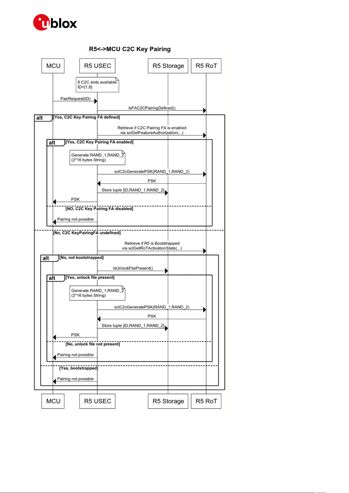
Figure 9: Chip-to-chip key pairing process
UBX-20013561 - R06 Design security Page 22 of 53
C1-Public

IoT Security-as-a-Service - Application Note
Although the guideline is that key pairing should happen in production phase and in a sanitize
environment (so before bootstrap) please note that this process can happen in 3 different scenarios:
(Please note that ISEP is a component of the u-blox Thingstream platform.)
• Before bootstrap (NOT registered with ISEP) and NOT claimed
Host MCU AT+USECC2C=0, <te_secret>
+USECC2C:0,0, <c2c_encryption_key>
MCU is responsible to store the te_secret and encryption_key.
• After bootstrap (Registered with ISEP) but NOT claimed
Host MCU AT+USECC2C=0, <te_secret>
NOT_ALLOWED
MCU can try again after device has been claimed.
• After bootstrap (Registered with ISEP) and claimed
Host MCU AT+USECC2C=0, <te_secret>
+USECC2C:0,0, <c2c_encryption_key>
MCU is responsible to store the te_secret and encryption_key.
5.1.3 Local C2C usage (Open secure session)
Open C2C channel:
• AT+USECC2C = 1, <TE_SECRET>
• An C2C channel is opened
• The <TE_SECRET> and <TERMINAL_DEV_NAME> are used to identify the key generation
material
• The identified material is used to generate a C2C key which is passed to the MSIO layer which
handles the encryption and decryption using the passed key.
• The <TERMINAL_DEV_NAME> is retrieved automatically from the ID of the AT terminal which is
being used to execute the c2c open channel command.
• A list of currently opened sessions is maintained. A new record is put on the list when a C2C
channel is opened.
UBX-20013561 - R06 Design security Page 23 of 53
C1-Public

IoT Security-as-a-Service - Application Note
Figure 10: Chip-to-chip pairing
UBX-20013561 - R06 Design security Page 24 of 53
C1-Public

IoT Security-as-a-Service - Application Note
C2C Secure session open
The +USECC2C=1, <te_secret> command opens a secure channel.
There is no guideline or recommendation when to open a secure session. This can happen in three
different scenarios.
• Before bootstrap (NOT registered with ISEP) and NOT claimed
Host MCU AT+USECC2C=1, <te_secret>
PLAIN_TEXT_AT_OK
ENCRYPTED_AT_COMMAND
ENCRYPTED_AT_OK
Having the right c2c_encryption_key (obtained in c2c key pairing phase) now MCU can decrypt
the ENCRYPTED_AT_OK message and get the AT_OK.
You only need to pay attention to the grace (or evaluation) period.
Grace period < registered to isep.
Grace period allows execution of localDPR 100 times.
Grace period allows execution of C2C open (-1)/close (-1) 100 times.
• After bootstrap (Registered with ISEP) but NOT claimed
Host MCU AT+USECC2C=1, <te_secret>
NOT_ALLOWED
MCU can try again after device has been claimed.
• After bootstrap (Registered with ISEP) and claimed
Host MCU AT+USECC2C=1, <te_secret>
PLAIN_TEXT_AT_OK
ENCRYPTED_AT_COMMAND
ENCRYPTED_AT_OK
Having the right c2c_encryption_key now MCU can decrypt the ENCRYPTED_AT_OK message
and get the AT_OK.
5.1.4 Local C2C usage (Close secure session)
The +USECC2C=2 command closes a secure channel.
You can close a session at any time (of course if you have already opened one).
(Please note that ISEP is a component of u-blox Thingstream platform.)
• Before bootstrap (NOT registered with ISEP) and NOT claimed
Host MCU AT+USECC2C=2
ENCRYPTED_AT_OK
Having the right c2c_encryption_key (obtained in c2c key pairing phase) now MCU can decrypt
the ENCRYPTED_AT_OK message and get the AT_OK.
• After bootstrap (Registered with ISEP) and claimed
Host MCU should first retrieve the c2c_encryption_key using the te_secrect. Then using the
right key encrypt AT+USECC2C=2
Host MCU ENCRYPTED AT COMMAND (AT+USECC2C=2)
ENCRYPTED_AT_OK
Having the right c2c_encryption_key (obtained in c2c key pairing phase) now MCU can decrypt
the ENCRYPTED_AT_OK message and get the AT_OK.
UBX-20013561 - R06 Design security Page 25 of 53
C1-Public

IoT Security-as-a-Service - Application Note
Command
Response
Description
AT+USECC2C=0,"A0324CFF236F45804865
…
Command
Response
Description
AT+USECC2C=1,"A0324CFF236F45804865
OK
Enter some other examples here
AT+USECC2C=2,"A0324CFF236F45804865
OK
5.1.5 Local C2C Rekeying
The +USECC2C=3 command triggers a rekeying of the current secure session. This can only be called
during a secure session.
The re-keying can only be executed within a C2C session. The session used for rekeying is closed.
Host MCU should first retrieve the c2c_encryption_key using the te_secrect. Then using the
right key encrypt AT+USECC2C=3
Host MCU ENCRYPTED AT COMMAND (AT+USECC2C=3)
ENCRYPTED_AT_OK
Having the right c2c_encryption_key (obtained in c2c key pairing phase) now MCU can decrypt the
ENCRYPTED_AT_OK message and get the AT_OK.
5.1.6 Local C2C use-case
The Chip-to-Chip process includes two stages:
1. Key pairing: in this phase new keys are created for a specific secure channel (identified by a HEX
string TE_SECRET) between the MT and the TE. Key pairing is available before bootstrap as a
trial, for about 50 operations. Once the module has bootstrapped, the key pairing is available
when the “LocalC2CKeyPairing” feature is enabled.
2. Usage: in this phase a secure channel, identified by TE_SECRET, is opened or closed between the
MT and the TE. C2C usage is available only after bootstrap, when the “LocalC2C” feature is
enabled.
R5<->MCU C2C key pairing example:
6C6C6F6F497D"
R5<->MCU C2C usage example:
6C6C6F6F497D"
6C6C6F6F497D"
Create key pairing for TE_SECRET
identifier A0324CFF…6F6F497D.
The C2C encryption key used for this
TE_SECRET is returned.
Open secure channel identified by
TE_SECRET A0324CFF…6F6F497D.
Close secure channel identified by
TE_SECRET A0324CFF…6F6F497D.
UBX-20013561 - R06 Design security Page 26 of 53
C1-Public
IoT Security-as-a-Service - Application Note
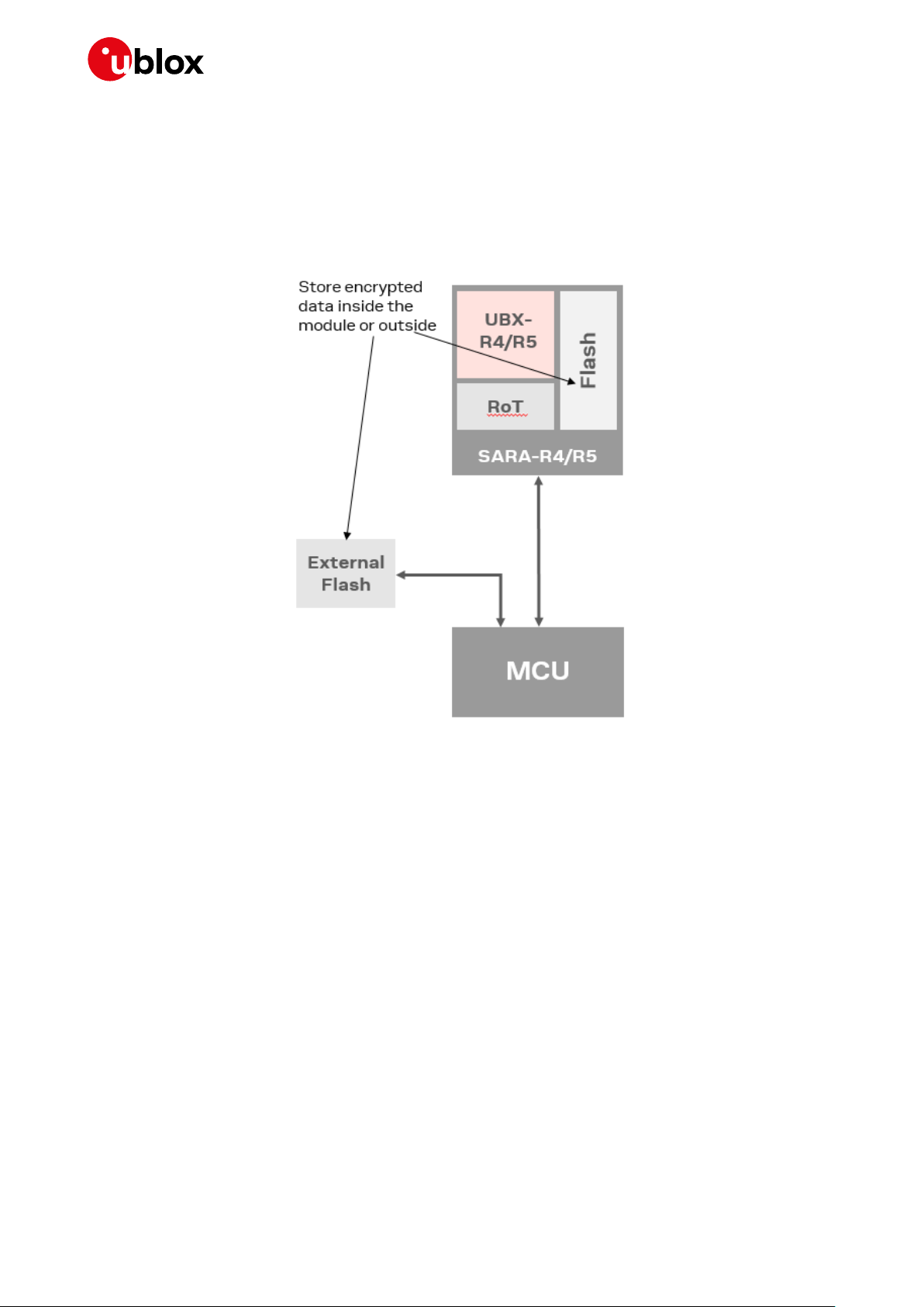
5.2 Local data protection
Managing symmetric crypto functions via the AT command allows the device to locally encrypt /
decrypt and authenticate critical data (e.g. certificates, tokens) on the device itself. The u-blox
solution enables customers to store critical data that has been encrypted using the RoT in a
non-secure component of the device, for example in the standard device memory.
Figure 11: Storing encrypted critical data
The method provides symmetric crypto services via AT command to allow the device to locally encrypt
& sign or decrypt & verify data.
Sensitive data used by the device (e.g. device certificates, CA or server certificates for (D)TLS pinning,
tokens, (D)TLS session resumption tickets, libraries result of expensive R&D efforts) is securely
stored.
UBX-20013561 - R06 Design security Page 27 of 53
C1-Public

IoT Security-as-a-Service - Application Note
AT+USECDATAENC=13,"ciphertextfile"
OK
AT+USECFILEDEC="ciphertextfile"
+USECFILEDEC: 13,"datatoencrypt
Figure 12: Local data protection process
5.2.1 Use case
The following AT command example encrypts the data string “datatoencrypt” and stores it within the
module file system in a file named “ciphertextfile” and decrypts the file “ciphertextfile” that was
stored in the module to read and display the text that was previously encrypted.
Command
> datatoencrypt
For further details, see the u-blox AT commands manual [2].
Response Description
"
OK
‘ciphertextfile’ is the name of the file in
which the encrypted text will be stored –
this is a free text name provided by the
customer.
‘datatoencrypt’ is the information to be
encrypted, for example: a private key,
some confidential data, etc.
‘datatoencrypt’ is a piece of information
decrypted (such as private key,
confidential data, etc.)
UBX-20013561 - R06 Design security Page 28 of 53
C1-Public

IoT Security-as-a-Service - Application Note
6 E2E Security
6.1 E2E Symmetric KMS
PSK cipher suites are ideal for embedded systems that have very limited computing power and only
talk to a very small number of servers. With PSK, each side of the connection already has an agreed
upon key to use during the TLS handshake. This reduces resource consumption for each session.
Pre-shared keys (PSK) provisioning is a highly scalable method for provisioning and managing session
unique PSKs for application layer security. A PSK and a PSKIdentity are generated by the RoT within
the module, and used to secure end-to-end communications (e.g. via DTLS) to a customer’s cloud
service. In particular, during (D)TLS handshake, the module sends the PSKIdentity generated by the
RoT inside the ClientKeyExchange message. Once the customer’s cloud service gets this information,
it will send the PSKIdentity to the u-blox security service (via a REST API) in order to retrieve the same
PSK that was used by the module to encrypt the end-to-end communications. The u-blox security
service uses the PSKIdentity to re-generate the PSK, without having to communicate with the
module.
This delivers the following advantages by:
• Achieving up to eight times reduction in the secure communication data overhead, and therefore
reducing cost for data consumption when compared with PKI-based TLS.
• Simplifying both the development and the actual process of obtaining the key by delegating the
key management to the u-blox solution.
Customers have the option of either:
• Using their own communication stack: in this scenario, the customer requests a PSK and
PSKIdentity pair from the module and uses it to establish a PSK based communication with its
own (D)TLS stack. This is described in Option 1 (see section 6.1.1.1).
• Using the communication stacks provided by u-blox: in this scenario the module is configured to
automatically establish a PSK based secure connection when trying to connect to a (D)TLS
endpoint using any Internet protocol based application provided by the module. This is described
in Option 2 (see section 6.1.1.2).
UBX-20013561 - R06 E2E Security Page 29 of 53
C1-Public

IoT Security-as-a-Service - Application Note
Device
Module
u-blox
software
Device software
PSK provisioning servic e
Billing service
u-blox services
portal
PSK provisioning engine
PSK identity
Key
Device owner
platform
(D)TLS handshake with PSK
identit y as pay load
(D) TLS data exch ange
8
Key
7
PSK identity
4
6 5
RoT
PSK + P SK identity
PSK request
(D)TLS endpoint
1 2
3
Figure 13: PSK provisioning
Figure 14: Key management service process managed by MCU
UBX-20013561 - R06 E2E Security Page 30 of 53
C1-Public
IoT Security-as-a-Service - Application Note
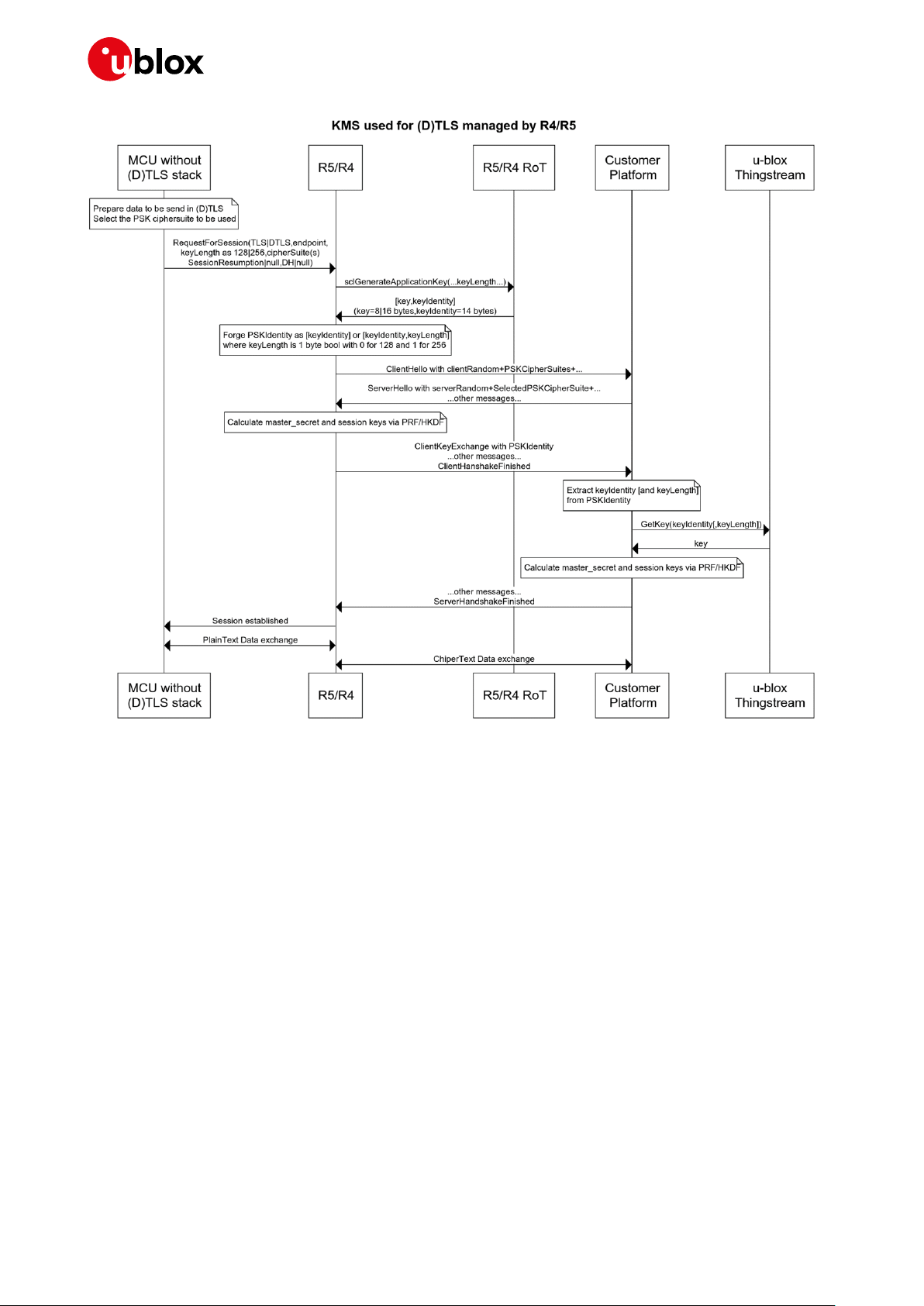
Figure 15: Key management service process managed by SARA-R4/R5 module
6.1.1 Use case
6.1.1.1 Option 1
Once the device has been bootstrapped and the pre-shared keys (PSK) provisioning functionality has
been enabled, this functionality can be called to access the required keys, as described below:
1. The customer’s application running on the device makes a request to the u-blox module and
retrieves a PSK and PSKIdentity pair from the RoT by using the AT+USECPSK command.
2. The customer configures their own (D)TLS stack to use the PSK and PSKIdentity that are
retrieved to secure the communication with its endpoint.
3. The PSKIdentity is sent during the (D)TLS handshake as the “Identity” element of the
ClientKeyExchange message, and the PSK is used to encrypt/decrypt the (D)TLS session data.
4. The customer’s remote service extracts the PSKIdentity from the ClientKeyExchange message
and forwards it to the u-blox security service via the GetPSK API.
5. The information received by the u-blox security service is used to:
5.1. Validate the customer
5.2. Validate the device making the request is assigned to this customer account
5.3. Confirm that PSK provisioning is enabled on this device
6. If all the actions in item 5 are true, i.e. the request is valid, then the u-blox security service passes
the PSK back to the customer’s remote service in the GetPSK API response.
7. The customer’s remote service can now use the received PSK to establish the (D)TLS session.
UBX-20013561 - R06 E2E Security Page 31 of 53
C1-Public

IoT Security-as-a-Service - Application Note
AT+USECPSK=16
+USECPSK: "1101000000112233445566778899",
OK
AT+USECPRF=0,8,"DEDD8D0A62D9D24059F392688D73
OK
AT+USECPRF=0,9,"1101000000112233445566778899
OK
The following AT command can be used to retrieve an identity and PSK value pair for encrypting pointto-point communication:
Command
Response Description
"DEDD8D0A62D9D24059F392688D738236"
It retrieves the PSK key identity and the PSK key
in hex format.
The module includes a (D)TLS security layer profile manager, which handles security profiles
containing (D)TLS connection properties. Each security profile can be associated to sockets or higher
level applications (e.g., HTTP, MQTT) using the module internal (D)TLS stack. In general, the
AT+USECPRF command is used to configure a security profile.
The following AT commands can be used to configure a security profile on the module with certain
PSKIdentity and PSK:
Command
8236",1
"
Response Description
Set PSK for security profile 0, in hex string
format. This PSK will be used to encrypt
communication on secure sockets/applications
associated to USECMNG profile 0.
Set PSKIdentity for security profile 0, as an ASCII
string. This PSKIdentity will be used to initiate
connection of secure sockets/applications
associated to USECMNG profile 0.
This way, associating a TCP socket to security profile 0, PSKIdentity and PSK will be used to handle
the TLS communication through that TCP socket.
Examples
Following are some examples of the procedure described above.
☞ These are example commands and do not use real world API keys or authorization headers. Actual
API secret key and authorization headers must first be created before running these commands.
1. Get PSK and PSKIdentity from RoT. For example, get a 16 bytes long PSK:
AT+USECPSK=16
+USECPSK: "11010008002F33244B115B0AEEB9","E5DE45B367DB690F2E17CF9D80A18E87"
OK
• 11010008002F33244B115B0AEEB9 is the PSKIdentity in hex format: this has to be sent to
the remote service during the (D)TLS handshake.
• E5DE45B367DB690F2E17CF9D80A18E87 is the actual PSK in hex format: this can be used
to encrypt the communication to the remote service.
2. Configure the (D)TLS stack to use the PSKIdentity and PSK generated by RoT.
This step depends on the (D)TLS stack used. We provide 2 examples:
a) Use OpenSSL command to test the connection to the remote service. Call OpenSSL this way:
openssl s_client -psk_identity "11010008002F33244B115B0AEEB9" -psk
"E5DE45B367DB690F2E17CF9D80A18E87" -connect <server_IP:server_port>
b) Use a modem internal socket to communicate to the remote service.
Configure a security profile (profile 0 in this example):
AT+USECPRF=0,8,"E5DE45B367DB690F2E17CF9D80A18E87",1
OK
UBX-20013561 - R06 E2E Security Page 32 of 53
C1-Public

IoT Security-as-a-Service - Application Note
AT+USECPRF=0,9,"11010008002F33244B115B0AEEB9"
OK
Then, create a socket and enable the secure option on the socket, associating the security
profile 0 to it:
AT+USOCR=6
+USOCR: 0 created socket with id 0
OK
AT+USOSEC=0,1,0 associate socket 0 to security profile 0
OK
Connect the socket to the remote service:
AT+USOCO=0,"<server_IP>",<server_port>
3. Analyzing the communication between client and remote service, we can see the PSKIdentity
being sent by the client in the ClientKeyExchange message during (D)TLS handshake:
4. Now we’re on the remote service side.
The actual way to extract the PSKIdentity from the ClientKeyExchange message can vary and
depends on the (D)TLS stack used.
For example, a server application using OpenSSL libraries and wishing to use PSKs for TLSv1.2
and below must provide a callback function called when the server receives the
ClientKeyExchange message. This function has the purpose of fetching the correct PSK starting
from the PSKIdentity retrieved from the client. The callback function is set by calling
SSL_CTX_set_psk_server_callback(SSL_CTX *ctx, SSL_psk_server_cb_func cb):
#include <openssl/ssl.h>
#include <openssl/err.h>
…
SSL_CTX *ctx;
const SSL_METHOD *method;
method = SSLv23_server_method();
ctx = SSL_CTX_new(method);
if (!ctx) {
ERR_print_errors_fp(stderr);
return -1;
}
SSL_CTX_set_ecdh_auto(ctx, 1);
SSL_CTX_use_psk_identity_hint(ctx, "hint hint");
SSL_CTX_set_psk_server_callback(ctx, psk_server_cb);
UBX-20013561 - R06 E2E Security Page 33 of 53
C1-Public

IoT Security-as-a-Service - Application Note
During (D)TLS handshake, when the server receives the ClientKeyExchange message, the
psk_server_cb function is called.
static unsigned int psk_server_cb(SSL *ssl,
const char *identity,
unsigned char *psk,
unsigned int max_psk_len) {
char* py_psk;
if (identity == NULL) {
return 0;
}
/* Retrieve the PSK for the given identity */
/* … */
See OpenSSL documentation for more details (https://www.openssl.org/docs/).
Once the PSKIdentity is retrieved, the customer can obtain the PSK via the GetPSK REST API call
(https://ssapi.services.u-blox.com/v1/GetPSK). Make sure to have an AuthToken to use for the
Authorization header – if not, call the Authorize API to get one.
We show the API call using cURL: we have to specify the PSKIdentity in the KeyID parameter and,
optionally, the PSK length (in bits) in the KeyLength parameter:
curl -X POST "https://ssapi.services.u-blox.com/v1/GetPSK" -H "accept:
application/json" -H "Authorization: [AuthToken]" -H "Content-Type: application/json"
-d "{ \"KeyID\": \"11010008002F33244B115B0AEEB9\", \"KeyLength\": \"128\"}"
In the previous C server application, it’s possible for example to use the libcurl library to perform
the API request. See libcurl documentation for more details (https://curl.haxx.se/libcurl/c/).
5. (Steps 5-6) The API returns a JSON containing the PSK encoded using base64:
{
"Key": "5d5Fs2fbaQ8uF8+dgKGOhw==",
"ROTPublicUID": "0002000089282245"
}
7. Considering the C server application from above, at this point the server can create a server
socket (sock_fd) and wrap it with the OpenSSL context from before (ctx):
SSL *ssl;
const SSL_METHOD *method;
method = SSLv23_server_method();
SSL_CTX_set_ecdh_auto(ctx, 1);
SSL_CTX_use_psk_identity_hint(ctx, "hint hint");
SSL_CTX_set_psk_server_callback(ctx, psk_server_cb);
ssl = SSL_new(ctx);
if (ssl == NULL) {
UBX-20013561 - R06 E2E Security Page 34 of 53
C1-Public

IoT Security-as-a-Service - Application Note
AT+USECPRF=0,11,1
OK
AT+USOCR=17
+USOCR: 0
OK
AT+USOSEC=0,1,0
OK
AT+USOCO=0,"myservice.com",443
OK
// Failed to initialise SSL buffer
return NULL;
}
if (0 == SSL_set_fd(ssl, sock_fd)) {
// Failed to configure IO for the SSL socket
ERR_print_errors_fp(stderr);
return NULL;
};
if (SSL_accept(ssl) <= 0) {
// Failed to setup SSL socket as server
ERR_print_errors_fp(stderr);
SSL_free(ssl);
return NULL;
}
At this point, the server application can exchange data through the secure socket by using SSL_read()
and SSL_write. See OpenSSL documentation for more details (https://www.openssl.org/docs/).
6.1.1.2 Option 2
⚠ This scenario will be supported in the next FW release of SARA-R5 (not in SARA-R4-x3B product
family)
A security manager profile can also be configured to generate a PSK and PSKIdentity pair
automatically when a socket negotiates a (D)TLS connection. In this case there is no need for further
configuration of the security profile (PSK and PSKIdentity) or configuration of external (D)TLS stack.
Once the device has been bootstrapped and the E2E Symmetric KMS functionality has been enabled,
use the following +USECPRF AT command for enabling automatic PSK and PSKIdentity generation
for the security profile number 0:
Command
Response Description
Enable for the security profile id 0 the use of PSK and
PSK identity during TLS connection negotiations.
All applications that rely on the security profile number 0 will now transmit the generated identity
value in the “Identity” field of the ClientKeyExchange message during (D)TLS handshake procedure in
order to negotiate the session keys.
☞ An external connection must be available, via a suitable SIM card, to run the following command
otherwise the following error result code will be displayed:
Command
Response Description
+CME ERROR: No connection to phone
Create a UDP socket.
In a similar way the PSK can be used to secure an HTTP connection (in the following example the
profile id 0 configured previously is re-used):
UBX-20013561 - R06 E2E Security Page 35 of 53
C1-Public
Enable SSL/TLS/DTLS on the socket #0 and specify to
use the profile id 0.
Connect the socket 0 to the server ‘myservice.com’ on
port 443.

IoT Security-as-a-Service - Application Note
Command
Response
Description
AT+UHTTP=0,1,"myservice.com"
OK
Set the HTTP server name for profile id 0.
AT+UHTTP=0,6,1,0
OK
AT+UHTTPC=0,1,"/"
OK
Send the GET command.
Device
Module
u-blox
software
Device software
Clear payload
E2E con fidentiality service
Billing service
u-blox services
portal
PSK pro visioning en gine
Key identity
Decryption
key and
parameters
Device owner
platform
E2E confiden tiality endpoint
Encrypted payload
3
Decryption
key and
parameters
7
First 16 bytes of
encrypted payload
(Key identity)
4
6
Encrypted payload
(includin g key
identity and MAC)
RoT
1
2
5
Enable SSL and use the security profile id 0 for the
HTTP profile #0.
6.2 End-to-end data protection
End-to-end data protection provides application layer encryption to device and module applications.
The application data is encrypted in the module and the corresponding decryption key and
parameters are made available via the REST API in the cloud for decryption.
The data can be:
• Encrypted on the device.
• Transferred over the internet independent of the protocols, servers or platforms used to achieve
this.
• Decrypted at a time of own choosing in the future.
The process does not depend on the security of the transport layers or storage mechanisms used
between the device and the end service.
☞ Note that on step (4) key identity will the first 11 or 16 bytes of the payload.
Figure 16: End-to-end data protection
UBX-20013561 - R06 E2E Security Page 36 of 53
C1-Public
IoT Security-as-a-Service - Application Note
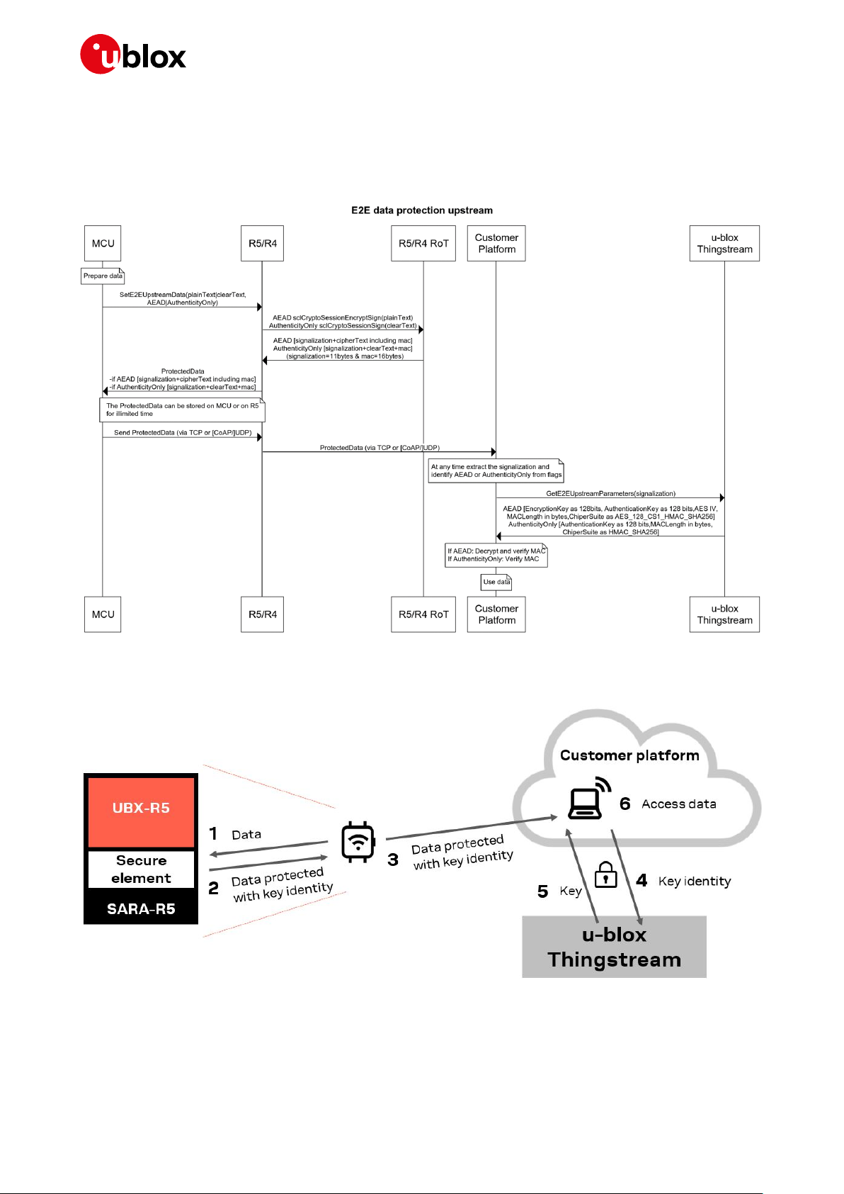
6.2.1 Upstream (device to cloud)
The application layer (device) wants to send a message to cloud securely without being involved in the
security stack. The sequence diagram below demonstrate the main players and the interactions
between them.
The diagram below demonstrates the steps from device to cloud.
Figure 17: Security steps from device to cloud
UBX-20013561 - R06 E2E Security Page 37 of 53
C1-Public

IoT Security-as-a-Service - Application Note
6.2.2 Downstream (cloud to device)
This service will be available in near future. In this scenario cloud would like to send a message to a
particular device securely. The sequence diagram demonstrates the players that the interactions
between them.
The diagram below demonstrates the steps from cloud to device.
Figure 18: Security steps from cloud to device
UBX-20013561 - R06 E2E Security Page 38 of 53
C1-Public

IoT Security-as-a-Service - Application Note
AT+USECE2EDATAENC=13
45,"••••‰("Mv3ðX~y•••‚•••
6.2.3 Use case
Once the device has been bootstrapped and the end-to-end data protection functionality has been
enabled, the end-to-end encryption functionality can be called, as described below:
1. The customer’s application running on the device makes an end-to-end encryption request to the
u-blox module on the same device passing the data to be encrypted by using the
AT+USECE2EDATAENC or the AT+USECE2EFILEENC command.
2. The u-blox module on the device encrypts the data and passes the authenticated and encrypted
data back to the customer’s application.
3. The customer’s application can then forward the authenticated and encrypted data to the
customer’s remote service using whatever means they choose. This may not be a direct call to
the customer’s remote service but may involve the transporting of the data via 1 to [N] insecure
internet servers (corresponding to step 3 in Figure 16).
During this transport phase the security and integrity of the data is still maintained as the data
is encrypted and authenticated.
The data can be retained by the customer’s remote service for decryption at a later date.
4. The key identity is extracted from the authenticated and encrypted data by reading the first
KI_LENGTH bytes, where KI_LENGTH is defined by the 4 most significant bits (nibble) in the
encrypted data:
5. If the nibble is set to 0x1, then KI_LENGHT is 16 bytes.
6. If the nibble is set to 0x2, then KI_LENGTH is 11 bytes.
The key identity is forwarded to the u-blox security service via GetE2EDecryptionParameters API
call, so that the matching decryption key and decryption parameters can be retrieved.
7. The information received by the u-blox security service is used to:
8. Validate the customer.
9. Validate the device making the request – Verify if this device is assigned to this customer account
10. Confirm that end-to-end data protection is enabled on this device
11. If all the actions in item 5 are true, i.e. the request is valid then the u-blox security service passes
the decryption key and decryption parameters back to the customers’ remote service.
12. The customers remote service can now decrypt and verify the authenticity of the data previously
passed to it (see item 3).
13. The decrypted data can now be used as required by the customer’s remote service.
The AT command +USECE2EDATAENC can be called to encrypt data:
Command
> datatoencrypt
This operation corresponds to step 2 in Figure 16.
Examples
Following are some examples of the procedure described above.
☞ These are example commands and do not use real world API keys or authorization headers. Actual
API secret key and authorization headers must first be created before running these commands.
1. (Steps 1-2-3) Let’s encrypt a simple «HELLO» message using AT+USECE2EDATAENC.
UBX-20013561 - R06 E2E Security Page 39 of 53
C1-Public
Response Description
ïÚ«S&p•“}•7D’?T¼}sÞ‰^÷WÙ"
OK
The command encrypts the secret string
‘datatoencrypt’, reading it from the AT interface, and
writes to AT interface the encrypted data, in binary
form, that can be decrypted at a later date at a
different location.

IoT Security-as-a-Service - Application Note
Use m-center in HEX mode (enable the checkbox on the top in the AT terminal). This way it’s
easier to parse the encrypted data returned by the AT command.
The AT command to send is:
AT+USECE2EDATAENC=5
> HELLO
The command returns the length of the encrypted data and the encrypted data itself:
+USECE2EDATAENC: 37, "<encrypted_data>"
In this case we get 37 bytes of encrypted data, which in hex format is:
1101000089291e26ec1aeb00744500000b874c81e91d623addf63bcebe64fe8b290efb4cd7
This is the encryption part of the process. At this point the encrypted data can be transferred to
the recipient by secure or insecure means.
The encrypted and authenticated data returned by the AT+USECE2EDATAENC command is
composed, in order, by:
• The key identity to be used in order to request decryption parameters.
• The cipher text.
• The MAC tag used to authenticate the data.
2. (Step 4) Suppose we are ready to decrypt the message – this could happen on any host that has
received the encrypted data at any time.
First thing to do is to extract the key identity from the encrypted data. The most significant
nibble (4 bits) of the encrypted data define the key identity length:
• If the nibble is set to 0x1, then the key identity is 16 bytes long.
• If the nibble is set to 0x2, then the key identity is 11 bytes long.
In our example we have:
Since the most significant nibble is 0x1, we extract the first 16 bytes:
Key identity:
1101000089291e26ec1aeb0074450000
The data encrypted using the +USECE2EDATAENC and +USECE2EFILEENC AT commands can
only be decrypted using a key obtained using the GetE2EDecryptionParameters REST API
(https://ssapi.services.u-blox.com/v1/GetE2EDecryptionParameters). Make sure to have an
AuthToken to use for the Authorization header – if not, call the Authorize API to get one.
Specifically, the REST API will provide the key and algorithm details needed to decrypt and verify
the authenticity of the cipher text generated by +USECE2EDATAENC and +USECE2EFILEENC.
The following command line examples use cURL to retrieve the PSK and decryption details, by
sending the key identity previously extracted in the “EncryptedHeader” parameter.
UBX-20013561 - R06 E2E Security Page 40 of 53
C1-Public

IoT Security-as-a-Service - Application Note
Request to be run on Linux and macOS:
curl -X POST "https://ssapi.services.u-blox.com/v1/GetE2EDecryptionParameters" -H
"accept: application/json" -H "Content-Type: application/json" -H Authorization:
[AuthToken] -d '{"EncryptedHeader":"1101000089291e26ec1aeb0074450000"}'
Request to be run on Windows:
curl -X POST "https://ssapi.services.u-blox.com/v1/GetE2EDecryptionParameters" -H
"accept: application/json" -H "Content-Type: application/json" -H Authorization:
[AuthToken] -d "{\"EncryptedHeader\":\"1101000089291e26ec1aeb0074450000\"}"
3. (Steps 5-6) If the request succeeds, the API response contains a JSON with this information:
{
"CipherSuite": "AES_128_CCM",
"Key": "ds/zy+Co/XYVMa14bqFh3w==",
"MACLength": 128,
"Nonce": "iSkeJuwa6wB0RQAA"
}
☞ The KI_LENGTH bytes long header returned by +USECE2EDATAENC and +USECE2EFILEENC,
when converted to an HEX string, is used in the curl request as the value of the EncryptedHeader
parameter.
The key and nonce values returned are base-64 encoded, and can be used to decode the
ciphertext, i.e. the data returned by +USECE2EDATAENC and +USECE2EFILEENC after having
removed the KI_LENGTH bytes header, using the algorithm specified, in this case AES with the
CCM mode. The MAC (16 for CCM mode or 8 bytes for CCM_8 mode) is appended at the end of
the encrypted payload and it must be verified by the customer.
4. (Step 7) From the API response we know:
• That we need to use the AES_128_CCM algorithm to decrypt the message
• The key and the nonce parameter to use as inputs for the algorithm
• That the MAC tag is 128 bits long (16 bytes)
Since the MAC tag is appended to the cipher text in the encoded data, we can now split the
response of AT+USECE2EDATAENC this way:
At this point we have all the inputs to decrypt and authenticate the encrypted data.
From the API response:
• Algorithm to use.
• Key and nonce.
From the encrypted AT+USECE2EDATAENC response:
• Cipher text.
• MAC tag.
We provide, as an example, a Python snippet which decrypts the cipher text by using the
PyCryptodome package (https://pycryptodome.readthedocs.io/en/latest/):
from base64 import b64decode
from Cryptodome.Cipher import AES
import binascii
UBX-20013561 - R06 E2E Security Page 41 of 53
C1-Public

IoT Security-as-a-Service - Application Note
def aesccm_dec(enc_data, keyb64, nonceb64, mac_len):
'''
Decrypt a cipher text using AES-CCM algorithm.
:param enc_data: the encrypted data string returned by AT+USECE2EDATAENC
:param keyb64: the decryption key returned by GetE2EDecryptionParameters
:param nonceb64: the nonce returned by GetE2EDecryptionParameters
:mac_len: the MAC tag length returned by GetE2EDecryptionParameters
'''
# decryption key and nonce are given by the API response as base64 strings
# they need to be converted to bytes (binary data)
key = b64decode(keyb64)
nonce = b64decode(nonceb64)
# ciphertext and MAC tag are extracted from the encrypted data as hex strings
# get key identity and MAC tag lengths
mac_len = mac_len // 8 # convert to bytes
key_id_len = 16 if enc_data[0] == '1' else 11 # in bytes
# get ciphertext and MAC tag and convert them to bytes (binary data)
ciphertext = binascii.unhexlify(enc_data[key_id_len*2:-mac_len*2])
tag = binascii.unhexlify(enc_data[-mac_len*2:])
try:
cipher = AES.new(key, AES.MODE_CCM, nonce=nonce)
plaintext = cipher.decrypt_and_verify(ciphertext, tag)
print("The message is: " + plaintext.decode('utf-8'))
except (ValueError, KeyError) as ex:
print("Incorrect decryption")
print(ex)
Running this function with the data from the example we get back our original “HELLO” message.
6.3 TLS version
TLS is a cryptographic protocol used to increase security over computer networks. TLS is the
successor of SSL although it is sometimes still referred to as SSL. It provides privacy and data
integrity between a TCP client (e.g., device) and a server. It ensures that data is reliable, comes from
an authenticated party, and is protected against ‘man-in-the-middle’ attacks.
☞ SARA-R4 "63B", "73B", “83B” product versions implement TLS v.1.2.
6.4 DTLS version
DTLS is a communications protocol designed to protect data privacy and prevent eavesdropping and
tampering. It is based on TLS and the main difference between DTLS and TLS is that DTLS uses UDP
and TLS uses TCP. It provides privacy and data integrity between a UDP client (e.g., device) and a
server. It ensures that data is reliable, comes from an authenticated party, and is protected against
‘man-in-the-middle’ attacks.
☞ SARA-R4 "63B", "73B", “83B” product versions implement DTLS v.1.2.
UBX-20013561 - R06 E2E Security Page 42 of 53
C1-Public

IoT Security-as-a-Service - Application Note
7 Access control
7.1 Zero Touch Provisioning
Zero touch provisioning is an automatic and secure way to enable and properly configure devices’
access to cloud services during deployment. It is an affordable (automatic) and secure way to enable
and properly configure our devices during deployment to connect to Core Cloud Services.
In order to access such services, the device must be identified and authorized. This is done by
generating and sending appropriate information (provisioned TLS certificates and keys) to the service
provider.
u-blox Security Service provides suitable certificates/keys to the module, and AT commands can be
used by the device connected to the module to retrieve this information.
Zero Touch Provisioning (ZTP) supports X. 509 standard as the format of public-key certificates so
any platform supporting this standard will be compatible with this service. Amazon Web Services
(AWS), Microsoft Azure and Alibaba cloud are some example platforms fully supported by ZTP.
Following are the steps in ZTP cloud onboarding procedure:
• Service (ZTP) registration
• Certificate provisioning
• Device registration
In this section we will go to details and explain these steps with more details.
7.1.1 Service registration
The operation can take place only once for the entire set of devices. The client is provided with a
registration code and a CA is generated if needed. In the diagrams bellow AWS is mentioned as the
example of a platform supporting X.509 standard.
☞ Please note that ISEP and CSP are two components of u-blox Thingstream platforms.
UBX-20013561 - R06 Access control Page 43 of 53
C1-Public

IoT Security-as-a-Service - Application Note
Figure 19: Service registration
7.1.2 Certificate provisioning
Operation triggered by the module when it connects to ISEP for the first time in its life cycle.
Figure 20: Certificate provisioning
UBX-20013561 - R06 Access control Page 44 of 53
C1-Public

IoT Security-as-a-Service - Application Note
7.1.3 Just in time provisioning
Operation made when the device connects to the Cloud for first time in its life cycle. The IoT Core is
provided with a Device certificate together with a PoP.
Figure 21: First time device connects to the cloud
UBX-20013561 - R06 Access control Page 45 of 53
C1-Public
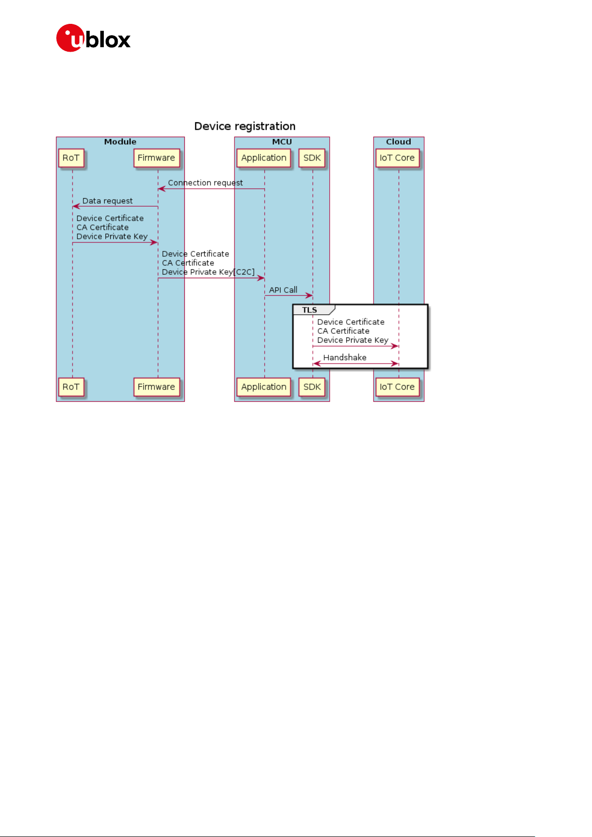
IoT Security-as-a-Service - Application Note
7.1.4 Device registration
Operation triggered every time the module requests an IoT Service.
Figure 22: Device registration for each service request
Ztp feature involves 4 different parameters to be used in AT command +USECDEVCERT Command:
0: Check provisioning: +USECDEVCERT=0
returns 0 if CaCertificate, DeviceCertificate and PrivateKey are present in RoT
1: Get CA Certificate: +USECDEVCERT=1
Returns the CACertificate
2: Get Device Certificate: +USECDEVCERT=2
Returns the DeviceCertificate
3: Get Private Key: +USECDEVCERT=3
Returns the PrivateKey
☞ For more information on the response time is provided in AT command manual. (You can search
the “AT command manual” for +USECCONN)
7.1.5 Use case (ZTP for Amazon Web Services)
Once the customer has an account on the AWS cloud platform, the below procedure can be followed
in order to provision a device with necessary certificates/keys to connect to the AWS IoT Core service
by using ZTP.
Needed tools: access to u-blox Security Service API, access to AWS IoT Core CLI, access to AT
interface.
The procedure is slightly different depending if the device(s) have already bootstrapped or not.
UBX-20013561 - R06 Access control Page 46 of 53
C1-Public

IoT Security-as-a-Service - Application Note
Here is the procedure:
1. Customer creates a CA certificate on the u-blox Security Service by calling the suitable API:
/ztp/rootca/create. The API returns the CA certificate, which can be locally stored in a file.
2. Customer gets its AWS IoT registration code (or Proof of Possession verification code) by using
the AWS CLI.
3. Customer generates a Proof-of-Possession certificate on u-blox Security Service, by calling the
suitable API: /ztp/rootca/popcertificate/generate. The API returns the PoP certificate, which can
be locally stored in a file.
4. Customer registers and activates the CA certificate got from u-blox Security Service on AWS IoT,
by using the AWS CLI or the AWS web console.
5. Customer enables the ZTPV1 feature on device:
5.1. If the module is already bootstrapped, call the API /device/provisioning/set.
5.2. If the module is not bootstrapped yet, call the API /deviceprofile/bootstrapprovisioning/set.
5.3. You can always check the feature authorization status by using the API
/device/provisioning/get.
6. At next synchronization of the module with the u-blox Security Service (bootstrap completion or
next security heartbeat message), the certificates and keys for AWS connection will be
provisioned to the device automatically. In order to get CA certificate, device certificate and
device private key, the customer’s application running on the device can use thte
AT+USECDEVCERT command on the module.
7. Customer registers the device certificate on AWS IoT by using the AWS CLI.
8. Customer creates and configures a Thing on AWS IoT by using the AWS CLI.
9. Customer can now connect the provisioned device to AWS and perform traffic by using any
external client of choice, e.g., AWS SDK.
Example
(Step1-4) First of all, we need to get a CA certificate from the u-blox Security Service to use for ZTP
and register it into the AWS cloud platform. These operations are a prerequisite to the ZTP feature
activation on the module, so they must be performed prior to it.
We call the API at https://ssapi.services.u-blox.com/v1/ztp/rootca/create to ask for a CA certificate
and pass a name for the CA certificate (used to identify it in later actions), and the validity time both
for the CA certificate and the device (or client).
Let’s for example create a “test-ca” CA certificate. We’ll send to the above API this content:
{
"CAName": "ubxaecel-ztp-aws-ca",
"CACertificateValidity": 1825,
"DeviceCertificateValidity": 1825
}
And we’ll receive a response like the following:
{
"CAName": "test-ca",
"CACertificateValidity": 1825,
"DeviceCertificateValidity": 1825,
"Certificate": "-----BEGIN CERTIFICATE<...>-----END CERTIFICATE-----",
"CreatedDate": "2020-07-03T09:07:44Z"
}
Save the CA certificate’s contents (here truncated) into a file.
Next, we need to create a Proof-of-Possession verification certificate from the u-blox Security Service,
and to do this we need the AWS IoT registration code associated to our AWS account. If you don’t
already have this information, you can get it by using the AWS CLI:
UBX-20013561 - R06 Access control Page 47 of 53
C1-Public

IoT Security-as-a-Service - Application Note
C:> aws iot get-registration-code
{
"registrationCode": "11fe30cf95<...>838a01be8313c"
}
Now we can call the https://ssapi.services.u-blox.com/v1/ztp/rootca/popcertificate/generate API
passing to it the CA certificate name used before and the AWS registration code:
{
"CAName": "test-ca",
"RegistrationCode": "11fe30cf95<...>838a01be8313c"
}
And we’ll get a response like the following:
{
"CAName": "test-ca",
"PoPCertificate": "-----BEGIN CERTIFICATE-----<...>-----END CERTIFICATE-----"
}
Save the PoP verification certificate contents (here truncated) into a file.
Now we have all the data to register the CA certificate into AWS IoT, and we do this by using the AWS
CLI:
C:> aws iot register-ca-certificate --ca-certificate file://test-ca.pem -verification-cert file://test-pop.pem
{
"certificateArn": "arn:aws:iot:eu-central1:27<...>24:cacert/f1b13a1b389c18d<...>0365ebba1",
"certificateId": "f1b13a1b389c18d<...>0365ebba1"
}
By visiting the AWS IoT web console, we can now see that an entry appeared in the Certificate
Authorities section:
As you can see, the CA certificate is currently inactive, so we need to activate it, and we can do this by
using the AWS CLI – reference the certificate id returned by the previous command:
C:> aws iot update-ca-certificate --certificate-id " f1b13a1b389c18d<...>0365ebba1" --newstatus ACTIVE
Now we can see on the AWS IoT web console that the status of the CA certificate is active:
UBX-20013561 - R06 Access control Page 48 of 53
C1-Public

IoT Security-as-a-Service - Application Note
(Step 5) Enable the ZTP feature on the device.
This can be done before the module bootstrapped or after the module bootstrapped: different APIs
have to be used depending on the case.
If the module is not bootstrapped, you need to provide the DeviceProfileUID sealed in the module and
the CA certificate name created before.
If the module is already bootstrapped, you need to provide the ROTPublicUID of the module and the
CA certificate name created before.
(Step 6-7) Once the ZTP feature is enabled on the module, the needed certificates/keys will be
provided by the u-blox Security Service to the module at bootstrap completion or at next security
heartbeat. You can get the provisioned data from the module by using the AT+USECDEVCERT
command.
The read command provides a status of the provisioning: if all the numbers returned by the command
are 0, it means that all the needed data have been provisioned:
AT+USECDEVCERT?
+USECDEVCERT: 0,0,0
OK
At this point, you can get the device (or client) certificate and key by using:
AT+USECDEVCERT=1
+USECDEVCERT: 1,"-----BEGIN CERTIFICATE----<...>
-----END CERTIFICATE----"
OK
AT+USECDEVCERT=0
+USECDEVCERT: 0,"-----BEGIN EC PRIVATE KEY----<...>
-----END EC PRIVATE KEY----"
OK
Save device certificate and key contents into two files.
Now use the AWS CLI to register the device certificate onto AWS IoT:
C:> aws iot register-certificate --certificate-pem file://client.crt --status
ACTIVE --ca-certificate-pem file://test-ca.pem
{
"certificateArn": "arn:aws:iot:eu-central1:27<...>24:cert/1197abb702b07797c4<...>46efd75965",
"certificateId": "1197abb702b07797c4<...>46efd75965"
}
By visiting the AWS IoT web console, we can now see that an entry appeared in the Certificates
section:
UBX-20013561 - R06 Access control Page 49 of 53
C1-Public

IoT Security-as-a-Service - Application Note
(Step 7) Create a Thing on AWS IoT for your device and associate the device certificate to it.
C:> aws iot create-thing --thing-name Thing1
{
"thingArn": "arn:aws:iot:eu-central-1:274183790524:thing/Thing1",
"thingName": "Thing1",
"thingId": "b442b530-291e-4bb6-bf18-3212c34024d0"
}
To associate the device certificate to the newly created Thing use the following command specifying
the Thing name and the device certificate’s ARN:
C:> aws iot attach-thing-principal --thing-name Thing1 --principal arn:aws:iot:eucentral-1:27<...>24:cert/1197abb702b07797c4<...>46efd75965
In order for your device to communicate with AWS IoT you need to create a security Policy on AWS IoT
and attach it to your Thing. For example, a Policy that allows the device to communicate with the AWS
Message Broker is as follows (substitute your AWS ID in the Resource fields):
{
"Version": "2012-10-17",
"Statement": [
{
"Effect": "Allow",
"Action": [
"iot:Publish",
"iot:Receive"
],
"Resource": "arn:aws:iot:eu-central-1:27<...>24:topic/test/topic"
},
{
"Effect": "Allow",
"Action": "iot:Subscribe",
"Resource": "arn:aws:iot:eu-central-1:27<...>24:topicfilter/test/topic"
},
{
"Effect": "Allow",
"Action": "iot:Connect",
"Resource": "arn:aws:iot:eu-central-1:27<...>24:client/test-*"
}
]
}
You can create a Policy directly from the AWS IoT web console, by selecting your Thing and following
the menus.
Now attach the Policy to your Thing:
C:\userdata\sandbox\ZTP>aws iot attach-policy --policy-name "ubxaecel-iot-policy" -
-target "arn:aws:iot:eu-central-1:
27<...>24:cert/1197abb702b07797c4<...>46efd75965"
At this point your device is ready to communicate with AWS IoT via any external client.
UBX-20013561 - R06 Access control Page 50 of 53
C1-Public

IoT Security-as-a-Service - Application Note
Abbreviation
Definition
Access point Namen
Datagram transport layer security
Information technology
Pre-shared keys
Representational state transfer application programming interface. Representational state
Root of trust
Set of open-source tools built around the OpenAPI specification for designing, building,
Transport layer security
Suite of the u-blox security services
A component of u-blox Thingstream platform
Appendix
A Glossary
APN
DeviceProfileUID
DTLS
E2E
IoT
IT
KMS
PSK
RAT
REST API
RoT
SE
Swagger
TEE
TLS
YAML
u-blox Thingstream
IoT Security-as-a-Service
ISEP
CSP
Table 1: Explanation of the abbreviations and terms used
Equivalent to a model number and can be used to identify a group of similar devices
End-to-end
Internet of Things
Key management service
Radio access technology
transfer is a software architectural style that defines a set of constraints to be used for
creating web services.
Secure element
documenting and consuming REST APIs
Trusted execution environment
A human-readable data-serialization language. It is commonly used for configuration files and in
applications where data is being stored or transmitted.
Service and account management platform
A component of u-blox Thingstream platform
UBX-20013561 - R06 Appendix Page 51 of 53
C1-Public

IoT Security-as-a-Service - Application Note
30-Apr-2020
hsia
Renaming some of parameters and some extension to PSK section.
R04
14-May-2020
hsia
Structural modification
2020
Related documents
[1] SARA-R4 series data sheet, UBX-16029218
[2] SARA-R4 AT commands manual, UBX-17003787
[3] SARA-R4 series system integration manual, UBX-16029218
[4] SARA-R4 application development guide, UBX-18019856
[5] FW update application note, UBX-17049154
[6] curl programming, TUTORIAL
☞ For regular updates to u-blox documentation and to receive product change notifications, register
on our homepage (www.u-blox.com).
☞ u-blox services webpage: https://www.u-blox.com/en/services
☞ u-blox services support email: thingstream-support@u-blox.com
Revision history
Revision
R01
R02
R03
R05
R06
Date Name Comments
18-Oct-2019 mace Initial release
22-Jan-2020 amer Extended document applicability to SARA-R5 series and other functionality
enhancements
22-May-
05-Oct-2020 hsia Extended document on chip-to-chip and Zero touch provisioning (ZTP)
hsia Examples
UBX-20013561 - R06 Related documents Page 52 of 53
C1-Public

IoT Security-as-a-Service - Application Note
u-blox Offices
Contact
For complete contact information, visit us at www.u-blox.com.
North, Central and South America
u-blox America, Inc.
Phone: +1 703 483 3180
E-mail: info_us@u-blox.com
Regional Office West Coast:
Phone: +1 408 573 3640
E-mail: info_us@u-blox.com
Technical Support:
Phone: +1 703 483 3185
E-mail: support@u-blox.com
Headquarters
Europe, Middle East, Africa
u-blox AG
Phone: +41 44 722 74 44
E-mail: info@u-blox.com
Support: support@u-blox.com
Asia, Australia, Pacific
u-blox Singapore Pte. Ltd.
Phone: +65 6734 3811
E-mail: info_ap@u-blox.com
Support: support_ap@u-blox.com
Regional Office Australia:
Phone: +61 2 8448 2016
E-mail: info_anz@u-blox.com
Support: support_ap@u-blox.com
Regional Office China (Beijing):
Phone: +86 10 68 133 545
E-mail: info_cn@u-blox.com
Support: support_cn@u-blox.com
Regional Office China (Chongqing):
Phone: +86 23 6815 1588
E-mail: info_cn@u-blox.com
Support: support_cn@u-blox.com
Regional Office China (Shanghai):
Phone: +86 21 6090 4832
E-mail: info_cn@u-blox.com
Support: support_cn@u-blox.com
Regional Office China (Shenzhen):
Phone: +86 755 8627 1083
E-mail: info_cn@u-blox.com
Support: support_cn@u-blox.com
Regional Office India:
Phone: +91 80 405 092 00
E-mail: info_in@u-blox.com
Support: support_in@u-blox.com
Regional Office Japan (Osaka):
Phone: +81 6 6941 3660
E-mail: info_jp@u-blox.com
Support: support_jp@u-blox.com
Regional Office Japan (Tokyo):
Phone: +81 3 5775 3850
E-mail: info_jp@u-blox.com
Support: support_jp@u-blox.com
Regional Office Korea:
Phone: +82 2 542 0861
E-mail: info_kr@u-blox.com
Support: support_kr@u-blox.com
Regional Office Taiwan:
Phone: +886 2 2657 1090
E-mail: info_tw@u-blox.com
Support: support_tw@u-blox.com
UBX-20013561 - R06 Contact Page 53 of 53
C1-Public
 Loading...