

Page 1

ZED-F9T
u-blox F9 high accuracy timing module
Integration Manual
Abstract
This document describes the features and application of ZED-F9T, a multiband GNSS module offering nanosecond level timing accuracy.
www.u-blox.com
UBX-19005590 - R01
Page 2

ZED-F9T-Integration Manual
Document Information
Title ZED-F9T
Subtitle u-blox F9 high accuracy timing module
Document type Integration Manual
Document number UBX-19005590
Revision and date R01 15-Mar-2019
Document status Advance Information
This document applies to the following products:
Product name Type number Firmware version PCN reference
ZED-F9T ZED-F9T-00B-00 TIM 2.00 N/A
u-blox reserves all rights to this document and the information contained herein. Products, names, logos and designs
described herein may in whole or in part be subject to intellectual property rights. Reproduction, use, modification or
disclosure to third parties of this document or any part thereof without the express permission of u-blox is strictly prohibited.
The information contained herein is provided "as is" and u-blox assumes no liability for the use of the information. No warranty,
either express or implied, is given with respect to, including but not limited to, the accuracy, correctness, reliability and fitness
for a particular purpose of the information. This document may be revised by u-blox at any time. For most recent documents,
please visit www.u blox.com.
Copyright © 2019, u-blox AG.
u-blox is a registered trademark of u-blox Holding AG in the EU and other countries.
UBX-19005590 - R01
Page 2 of 80
Advance Information
Page 3

ZED-F9T-Integration Manual
Contents
1 Integration manual structure............................................................................................ 6
2 System description............................................................................................................... 7
2.1 Overview.................................................................................................................................................... 7
2.1.1 Differential timing.......................................................................................................................... 7
2.2 Architecture..............................................................................................................................................7
2.2.1 Block diagram..................................................................................................................................8
3 Receiver functionality..........................................................................................................9
3.1 Receiver configuration........................................................................................................................... 9
3.1.1 Changing the receiver configuration..........................................................................................9
3.1.2 Default GNSS configuration.........................................................................................................9
3.1.3 Default interface settings..........................................................................................................10
3.1.4 Basic receiver configuration...................................................................................................... 10
3.1.5 Differential timing mode configuration...................................................................................12
3.1.6 Legacy configuration interface compatibility........................................................................ 15
3.1.7 Navigation configuration............................................................................................................ 15
3.2 Geofencing..............................................................................................................................................20
3.2.1 Introduction...................................................................................................................................20
3.2.2 Interface......................................................................................................................................... 21
3.2.3 Geofence state evaluation......................................................................................................... 21
3.2.4 Using the geofence pin state output...................................................................................... 21
3.3 Interfaces................................................................................................................................................21
3.3.1 UART interfaces........................................................................................................................... 23
3.3.2 SPI interface..................................................................................................................................23
3.3.3 USB interface................................................................................................................................23
3.3.4 D_SEL interface............................................................................................................................24
3.3.5 RESET_N interface...................................................................................................................... 24
3.3.6 SAFEBOOT_N interface..............................................................................................................24
3.3.7 TIMEPULSE interface..................................................................................................................25
3.3.8 Display data channel (DDC).......................................................................................................25
3.3.9 Antenna supervisor..................................................................................................................... 25
3.3.10 EXTINT......................................................................................................................................... 28
3.3.11 Communication ports............................................................................................................... 28
3.4 Multiple GNSS assistance (MGA)..................................................................................................... 33
3.4.1 AssistNow Online......................................................................................................................... 33
3.4.2 Host software............................................................................................................................... 34
3.4.3 AssistNow Online sequence...................................................................................................... 34
3.4.4 Flow control................................................................................................................................... 35
3.4.5 Authorization................................................................................................................................ 35
3.4.6 Service parameters......................................................................................................................35
3.4.7 Multiple servers............................................................................................................................37
3.5 Clocks and time.....................................................................................................................................37
3.5.1 Receiver local time.......................................................................................................................37
3.5.2 Navigation epochs....................................................................................................................... 37
3.5.3 iTOW timestamps........................................................................................................................38
UBX-19005590 - R01
Contents Page 3 of 80
Advance Information
Page 4

ZED-F9T-Integration Manual
3.5.4 GNSS times...................................................................................................................................38
3.5.5 Time validity..................................................................................................................................39
3.5.6 UTC representation..................................................................................................................... 39
3.5.7 Leap seconds................................................................................................................................ 40
3.5.8 Real time clock............................................................................................................................. 40
3.5.9 Date.................................................................................................................................................40
3.6 Timing functionality............................................................................................................................. 41
3.6.1 Time pulse..................................................................................................................................... 41
3.6.2 Timemark.......................................................................................................................................45
3.7 Security (operating, monitoring and maintaining)........................................................................ 46
3.7.1 Receiver status monitoring....................................................................................................... 46
3.7.2 Spoofing detection / monitoring............................................................................................... 48
3.8 u-blox protocol feature descriptions................................................................................................ 48
3.8.1 Broadcast navigation data.........................................................................................................48
3.9 Forcing a receiver reset....................................................................................................................... 54
4 Design..................................................................................................................................... 56
4.1 Pin assignment......................................................................................................................................56
4.2 Power supply.......................................................................................................................................... 58
4.2.1 VCC: Main supply voltage.......................................................................................................... 58
4.2.2 V_BCKP: Backup supply voltage............................................................................................... 58
4.2.3 ZED-F9T power supply............................................................................................................... 59
4.3 ZED-F9T minimal design....................................................................................................................59
4.4 Antenna...................................................................................................................................................60
4.4.1 Antenna bias.................................................................................................................................61
4.5 EOS/ESD precautions.......................................................................................................................... 64
4.5.1 ESD protection measures.......................................................................................................... 64
4.5.2 EOS precautions...........................................................................................................................65
4.5.3 Safety precautions...................................................................................................................... 65
4.6 Electromagnetic interference on I/O lines.......................................................................................65
4.6.1 General notes on interference issues...................................................................................... 66
4.6.2 In-band interference mitigation................................................................................................ 66
4.6.3 Out-of-band interference........................................................................................................... 67
4.7 Layout......................................................................................................................................................67
4.7.1 Placement......................................................................................................................................67
4.7.2 Package footprint and solder mask......................................................................................... 67
4.7.3 Layout guidance........................................................................................................................... 67
4.8 Design guidance....................................................................................................................................69
4.8.1 General considerations............................................................................................................... 69
4.8.2 backup battery............................................................................................................................. 69
4.8.3 RF front-end circuit options...................................................................................................... 70
4.8.4 Antenna/ RF input....................................................................................................................... 70
4.8.5 Ground pads..................................................................................................................................71
4.8.6 Schematic design........................................................................................................................ 71
4.8.7 Layout design-in guideline......................................................................................................... 71
5 Product handling................................................................................................................. 72
5.1 ESD handling precautions.................................................................................................................. 72
5.2 Soldering.................................................................................................................................................72
5.3 Tapes....................................................................................................................................................... 75
5.4 Reels........................................................................................................................................................ 76
UBX-19005590 - R01
Contents Page 4 of 80
Advance Information
Page 5

ZED-F9T-Integration Manual
5.5 Moisture sensitivity levels.................................................................................................................. 76
6 Appendix................................................................................................................................ 77
6.1 Glossary...................................................................................................................................................77
7 Related documents............................................................................................................ 78
8 Revision history................................................................................................................... 79
UBX-19005590 - R01
Contents Page 5 of 80
Advance Information
Page 6

ZED-F9T-Integration Manual
1 Integration manual structure
This document provides a wealth of information to enable a successful design with the ZED-F9T
module. The manual is structured according to system, software and hardware aspects.
The first section, "System description" outlines the basics of the ZED-F9T timing receiver.
The following section "Receiver functionality" provides an exhaustive description of the receiver's
functionality. Beginning with the new configuration concept both existing and new users should read
this section to understand the new messages employed. Most of the following sub-sections should
be familiar to existing users of u-blox positioning products, however some changes are introduced
owing to the new configuration concept.
The sections from "Design" onwards addresses hardware options when designing the ZED-F9T
into a new product. This part gives power supply recommendations and provides guidance for
circuit design and PCB lay-out assistance. An antenna section provides design information and
recommendation for this important component. A final "Design guidance" section helps the
designer to check that crucial aspects of the design-in process have been carried out.
The final section addresses the major product handling concerns giving guidance on ESD
precautions, production soldering considerations and module delivery tape and reel information.
UBX-19005590 - R01
1 Integration
manual structure
Page 6 of 80
Advance Information
Page 7

ZED-F9T-Integration Manual
2 System description
2.1 Overview
The ZED-F9T is a multi-band GNSS module offering 5 ns (1-sigma) timing accuracy with
unparalleled low power consumption.
The ZED-F9T incorporates the u-blox F9 multi-band platform in a small surface mount device with
a form factor of 22 x 17 mm.
2.1.1 Differential timing
The u-blox ZED-F9T high accuracy timing receiver takes local timing accuracy to the next level with
its differential timing mode.
In differential timing mode correction data is exchanged with other neighboring ZED-F9T timing
receivers via a communication network. In differential timing mode the ZED-F9T can operate either
as a master reference station, or as a slave station.
When ZED-F9T acts as a master reference timing station, it sends RTCM 3.3 differential corrections
to slave receivers.
When ZED-F9T acts as a slave receiver, it receives differential corrections RTCM 3.3 messages and
aligns its time pulse to the master reference station.
2.2 Architecture
The ZED-F9T module provides all the necessary RF and baseband processing to enable multi-band,
multi-constellation operation. The block diagram below shows the key functionality implemented in
the module.
UBX-19005590 - R01
2 System description Page 7 of 80
Advance Information
Page 8

ZED-F9T-Integration Manual
2.2.1 Block diagram
Figure 1: ZED-F9T block diagram
An active antenna is mandatory with the ZED-F9T.
UBX-19005590 - R01
2 System description Page 8 of 80
Advance Information
Page 9

ZED-F9T-Integration Manual
3 Receiver functionality
This section describes the ZED-F9T operational features and their configuration.
3.1 Receiver configuration
The ZED-F9T is fully configurable with UBX configuration interface keys. The configuration
database in the receiver's RAM holds the current configuration, which is used by the receiver
at run-time. It is constructed on start-up of the receiver from several sources of configuration.
The configuration interface and the available keys are described fully in the ZED-F9T Interface
Description [2].
A configuration setting stored in RAM remains effective until power-down or reset. If stored in
BBR (battery backed RAM), the setting will be used as long as the backup battery supply remains.
Configuration settings can be saved permanently in flash memory.
The configuration interface has changed from earlier u-blox positioning receivers.
There is some backwards compatibility however, users are strongly advised to adopt the
configuration interface described in this document. See legacy UBX-CFG message fields
reference section in the ZED-F9T Interface Description [2].
Configuration interface settings are held in a database consisting of separate configuration
items. An item is made up of a key ID and value pair. Related items are grouped together and
identified under a common group name: CFG-GROUP-ITEM; a convention used in u-center and
within this document. Within u-center, a configuration group is identified as "Group name" and the
configuration item is identified as the "item name" under the "Generation 9 Configuration View" "Advanced Configuration" view.
The UBX messages available to change or poll the configurations are the UBX-CFG-VALSET, UBXCFG-VALGET, and UBX-CFG-VALDEL messages. For more information about these messages and
the configuration keys see the configuration interface section in the ZED-F9T Interface Description
[2].
3.1.1 Changing the receiver configuration
All configuration messages, including legacy UBX-CFG messages, will result in a UBX-ACK-ACK
or UBX-ACK-NAK response. If several configuration messages are sent without waiting for this
response then the receiver may pause processing of input messages until processing of a previous
configuration message has been completed. When this happens a warning message "wait for cfg
ACK" will be sent to the host.
3.1.2 Default GNSS configuration
The ZED-F9T default GNSS configuration is set as follows:
• GPS: L1C/A, L2C
• GLONASS: L1OF, L2OF
• Galileo: E1B/C, E5b
• BeiDou: B1I, B2I
• QZSS: L1C/A, L2C
SBAS is also supported but not enabled in the default GNSS configuration. SBAS is not
recommended for timing applications.
For more information about default configuration, see the ZED-F9T Interface Description [2].
UBX-19005590 - R01
3 Receiver functionality Page 9 of 80
Advance Information
Page 10

ZED-F9T-Integration Manual
3.1.3 Default interface settings
Interface Settings
UART1 output 38400 Baud, 8 bits, no parity bit, 1 stop bit. NMEA GGA, GLL, GSA, GSV, RMC, VTG, TXT (and no
UBX) messages are output by default.
UART1 input 38400 Baud, 8 bits, no parity bit, 1 stop bit. UBX, NMEA and RTCM 3.3 messages are enabled by
default.
UART2 output 38400 Baud, 8 bits, no parity bit, 1 stop bit. No host interface (UBX). Configured by default to
allow RTCM 3.3 as an output protocol. NMEA can also be configured as an output protocol.
UART2 input 38400 Baud, 8 bits, no parity bit, 1 stop bit. No Host interface support (UBX). RTCM 3.3 protocol
enabled by default
USB output NMEA GGA, GLL, GSA, GSV, RMC, VTG, TXT (and no UBX) messages are output by default.
USB input UBX, NMEA, RTCM 3.3 protocols enabled by default.
DDC
Fully compatible with the I2C industry standard, available for communication with an external host
CPU or u-blox cellular modules, operated in slave mode only. Default messages activated as in
UART1. Input/output protocols available as in UART1. Maximum bit rate 400 kb/s.
SPI Allow communication to a host CPU, operated in slave mode only. Default messages activated as
in UART1. Input/output protocols available as in UART1. SPI is not available unless D_SEL pin is
set to low (see section D_SEL interface in ZED-F9T Integration Manual).
Table 1: Default interface settings
Refer to the u-blox ZED-F9T Interface Description [2] for information about further
settings.
By default the ZED-F9T outputs NMEA 4.10 messages that include satellite data for all GNSS bands
being received. This results in a higher-than-before NMEA load output for each navigation period.
Make sure the UART1 baud rate being used is sufficient for the selected navigation rate and the
number of GNSS signals being received.
3.1.4 Basic receiver configuration
This section summarizes the basic receiver configuration most commonly used.
3.1.4.1 Communication interface configuration
Several configuration groups allow operation mode configuration of the various communications
interfaces. These include parameters for the data framing, transfer rate and enabled input/output
protocols. See Communication ports section for details. The configuration groups available for each
interface are:
Interface Configuration groups
UART1 CFG-UART1-*, CFG-UART1INPROT-*, CFG-UART1OUTPROT-*
UART2 CFG-UART2-*, CFG-UART2INPROT-*, CFG-UART2OUTPROT-*
USB CFG-USB-*, CFG-USBINPROT-*, CFG-USBOUTPROT-*
I2C
CFG-I2C-*, CFG-I2CINPROT-*, CFG-I2COUTPROT-*
SPI CFG-SPI-*, CFG-SPIINPROT-*, CFG-SPIOUTPROT-*
Table 2: Default configurations
3.1.4.2 Message output configuration
The rate of NMEA and UBX protocol output messages are configurable.
If the rate configuration value is zero, then the corresponding message will not be output. Values
greater than zero indicate how often the message is output.
For periodic output messages the rate relates to the event the message is related to. For example,
the UBX-NAV-PVT (navigation position velocity and time solution) is related to the navigation epoch.
If the rate of this message is set to one (1), it will be output for every navigation epoch. If the rate
UBX-19005590 - R01
3 Receiver functionality Page 10 of 80
Advance Information
Page 11

ZED-F9T-Integration Manual
is set to two (2), it will be output every other navigation epoch. The rates of the output messages
are individually configurable per communication interface. See the CFG-MSGOUT-* configuration
group.
Some messages, such as UBX-MON-VER, are not periodic and will only be output as the answer to
a poll request.
The UBX-INF-* information messages are non-periodic output messages that do not have a
message rate configuration. Instead they can be enabled for each communication interface via the
CFG-INFMSG-* configuration group.
All message output is additionally subject to the protocol configuration of the
communication interfaces. Messages of a given protocol will not be output until the protocol
is enabled for output on the interface (see previous section).
3.1.4.3 GNSS signal configuration
The GNSS constellations and bands are configurable with configuration keys. Each GNSS
constellation can be enabled or disabled independently. A GNSS constellation is considered to be
enabled when the constellation enable key is set and at least one of the constellation's band keys
are enabled.
ZED-F9T only supports certain combinations of constellations and bands. For all constellations,
both L1 and L2 bands must either be enabled or disabled. BeiDou B2 is the exception (can either
have BeiDou B1+B2 or B1-only). Unsupported combinations will be rejected with a UBX-ACK-NAK
and the warning: "invalid sig cfg" will be sent via UBX-INF and NMEA-TXT messages (if enabled).
The following table shows possible configuration key combinations for the GPS constellation.
Constellation key
CFG-SIGNAL-GPS_ENA
Band key
CFG-SIGNAL-GPS_L1CA_ENA
Band key
CFG-SIGNAL-GPS_L2C_ENA
Constellation
enabled?
false (0) false (0) false (0) no
false (0) false (0) true (1) no
false (0) true (1) false (0) no
false (0) true (1) true (1) no
true (1) false (0) false (0) no
true (1) false (0) true (1) Unsupported
combination
true (1) true (1) false (0) Unsupported
combination
true (1) true (1) true (1) yes
Table 3: Example of possible values of configuration items for the GPS constellation
3.1.4.4 Antenna supervisor configuration
This section describes the antenna supervisor configuration, its use and restrictions.
The antenna supervisor is used to control an active antenna. The configuration of the antenna
supervisor allows the following:
• Control voltage supply to the antenna, which allows the antenna supervisor to cut power to the
antenna in the event of a short circuit or optimize power to the antenna in power save mode.
• Detect a short circuit in the antenna and auto recover the antenna supply in such event.
• Detect an open antenna, which can be used to tell if the antenna has been disconnected.
See the table below, for a description of the configuration items related to the antenna supervisor
operation.
UBX-19005590 - R01
3 Receiver functionality Page 11 of 80
Advance Information
Page 12

ZED-F9T-Integration Manual
Configuration item Description Comments
CFG-HW-ANT_CFG_VOLTCTRL Enable active antenna voltage control
CFG-HW-ANT_CFG_SHORTDET Enable short circuit detection
CFG-HW-ANT_CFG_SHORTDET_POL Short antenna detection polarity Set to 1 if the required logic polarity is
active-low (default)
CFG-HW-ANT_CFG_OPENDET Enable open circuit detection
CFG-HW-ANT_CFG_OPENDET_POL Open antenna detection polarity Set to 1 if the required logic polarity is
active-low (default)
CFG-HW-ANT_CFG_PWRDOWN Power down antenna supply if Short
Circuit is detected
CFG-HW-ANT_CFG_PWRDOWN_POL Power down antenna logic polarity Set to 1 if the required logic polarity is
active-high (default)
CFG-HW-ANT_CFG_RECOVER Enable auto recovery in the event of a
short circuit
To use this feature, short circuit
detection should be enabled. See CFGHW-ANT_CFG_SHORTDET
CFG-HW-ANT_SUP_SWITCH_PIN PIO-Pin (PIO number) used for switching
antenna supply
It is recommended that you use the
default PIO and assigned pin
CFG-HW-ANT_SUP_SHORT_PIN PIO-Pin (PIO number) used for detecting
a short in the antenna supply
It is recommended that you use the
default PIO and assigned pin
CFG-HW-ANT_SUP_OPEN_PIN PIO-Pin (PIO number) used for detecting
open/not connected antenna
It is recommended that you use the
default PIO and assigned pin
Table 4: Antenna supervisor configuration
It is possible to obtain the status of the antenna supervisor through the UBX-MON-RF message.
Moreover, any changes in the status of the antenna supervisor are reported to the host interface
in the form of notice messages. See the tables below for a description of the antenna state status
and the antenna power status.
Status Description
OFF Antenna is off
ON Antenna is on
DONTKNOW Antenna power status is not known
Table 5: Antenna power status
3.1.5 Differential timing mode configuration
In differential timing mode the ZED-F9T can operate either as a master reference station or as a
slave station. Using the RTCM3 protocol, the master sends timing corrections to the slave via a
communication link enabling the slave to compute its time relative to the master with high accuracy.
This section describes how to configure the ZED-F9T high accuracy timing receiver as a master
reference station and as slave station. The section begins with a note describing the RTCM protocol
and corresponding supported message types.
3.1.5.1 RTCM corrections
RTCM is a binary data protocol for communication of GNSS correction information. The ZED-F9T
high accuracy timing receiver supports RTCM as specified by RTCM 10403.3, Differential GNSS
(Global Navigation Satellite Systems) Services – Version 3 (October 7, 2016).
The RTCM specification is currently at version 3.3 and RTCM version 2 messages are not supported
by this standard. Users can download the standard from the RTCM website here.
To modify the RTCM input/output settings, see the configuration section in the u-blox ZED-F9T
Interface Description [2].
UBX-19005590 - R01
3 Receiver functionality Page 12 of 80
Advance Information
Page 13

ZED-F9T-Integration Manual
3.1.5.2 List of supported RTCM input messages
Message Description
RTCM 1005 Stationary RTK reference station ARP
RTCM 1077 GPS MSM7
RTCM 1087 GLONASS MSM7
RTCM 1097 Galileo MSM7
RTCM 1127 BeiDou MSM7
RTCM 1230 GLONASS code-phase biases
RTCM 4072 Additional reference station information
Table 6: ZED-F9T supported input RTCM version 3.3 messages
3.1.5.3 List of supported RTCM output messages
Message Description
RTCM 1005 Stationary RTK reference station ARP
RTCM 1077 GPS MSM7
RTCM 1087 GLONASS MSM7
RTCM 1097 Galileo MSM7
RTCM 1127 BeiDou MSM7
RTCM 1230 GLONASS code-phase biases
RTCM 4072 Additional reference station information
Table 7: ZED-F9T supported output RTCM version 3.3 messages
3.1.5.4 Timing receiver position
Time mode is a special receiver mode where the position of the receiver is known and fixed and only
the time and frequency is calculated using all available satellites. This mode allows for maximum
time accuracy, for single-SV solutions, and also for using the receiver as a stationary reference
station.
In order to use time mode, the receiver's position must be known as exactly as possible. Errors in the
fixed position will translate into time errors depending on the satellite constellation.
The following procedures can be used to initialize the timing receiver position:
• Using built-in survey-in procedure to estimate the position.
• Entering coordinates independently generated or taken from an accurate position such as a
survey marker.
3.1.5.4.1 Survey-in
Survey-in is a procedure that is carried out prior to entering Time mode. It estimates the receiver
position by building a weighted mean of all valid 3D position solutions.
Two major parameters are required when configuring:
• A minimum observation time defines the minimum observation time independent of the
actual number of fixes used for the position estimate. Values can range from one day for high
accuracy requirements to a few minutes for coarse position determination.
• A 3D position standard deviation defines a limit on the spread of positions that contribute to
the calculated mean.
Survey-in ends when both requirements are successfully met. The Survey-in status can be queried
using the UBX-NAV-SVIN message.
The timing receiver should not be fed RTCM corrections while it is in survey-in mode.
UBX-19005590 - R01
3 Receiver functionality Page 13 of 80
Advance Information
Page 14

ZED-F9T-Integration Manual
To configure a timing receiver into Survey-in mode (CFG-TMODE-MODE=SURVEY_IN), the following
items are required:
Configuration item Description
CFG-TMODE-MODE Receiver mode (disabled, survey-in or fixed)
CFG-TMODE-SVIN_MIN_DUR Survey-in minimum duration
CFG-TMODE-SVIN_ACC_LIMIT Survey-in position accuracy limit. The accuracy of given coordinates in 0.0001
meters (i.e. value 100 equals 1 cm)
Table 8: Configuration items used for setting a timing receiver into Survey-in mode
3.1.5.4.2 Fixed position
Here the timing receiver position coordinates are entered manually. Any error in the timing receiver
position will directly translate into timing errors.
To configure into Fixed mode (CFG-TMODE-MODE=FIXED), the following items are relevant:
Configuration item Description
CFG-TMODE-MODE Receiver mode (disabled or survey-in or fixed)
CFG-TMODE-POS_TYPE Determines whether the ARP position is given in ECEF or LAT/LON/HEIGHT
CFG-TMODE-ECEF_X ECEF X coordinate of the ARP position, coordinate in centimeters
CFG-TMODE-ECEF_Y ECEF Y coordinate of the ARP position, coordinate in centimeters
CFG-TMODE-ECEF_Z ECEF Z coordinate of the ARP position, coordinate in centimeters
CFG-TMODE-LAT Latitude of the ARP position, coordinate in 1e-7 degrees
CFG-TMODE-LON Longitude of the ARP position, coordinate in 1e-7 degrees
CFG-TMODE-HEIGHT Height of the ARP position, coordinate in centimeters
CFG-TMODE-ECEF_X_HP High-precision ECEF X coordinate of the ARP position, coordinate in 0.1 millimeters
CFG-TMODE-ECEF_Y_HP High-precision ECEF Y coordinate of the ARP position, coordinate in 0.1 millimeters
CFG-TMODE-ECEF_Z_HP High-precision ECEF Z coordinate of the ARP position, coordinate in 0.1 millimeters
CFG-TMODE-LAT_HP High-precision latitude of the ARP position, coordinate in 1e-9 degrees
CFG-TMODE-LON_HP High-precision longitude of the ARP position, coordinate in 1e-9 degrees
CFG-TMODE-HEIGHT_HP High-precision height of the ARP position, coordinate in 0.1 millimeters
CFG-TMODE-FIXED_POS_ACC Fixed position 3D accuracy estimate
Table 9: Configuration items used for setting a timing receiver into fixed mode
Once the receiver is set in fixed mode, select the position format to use: either LLH or ECEF with
optional high precision (mm) coordinates compared to the standard cm value.
For example, with CFG-TMODE-POS_TYPE=ECEF the timing receiver antenna position can be
entered to cm precision using CFG-TMODE-ECEF_X, CFG-TMODE-ECEF_Y, CFGTMODE-ECEF_Z.
For high precision (mm) coordinates use CFG-TMODEECEF_X_HP, CFG-TMODE-ECEF_Y_HP, CFGTMODE-ECEF_Z_HP. The same applies with corresponding coordinates used with CFG-TMODEPOS_TYPE=LLH.
If the timing receiver is moved during operation then new position coordinates must be
configured.
3.1.5.5 Master reference station
When the ZED-F9T high accuracy timing receiver acts as a master timing station, it sends RTCM
3.3 differential corrections to slave receivers. Corrections are generated after a timing fix calculation
in order to remove the master receiver's clock offset.
3.1.5.5.1 Master reference station: RTCM output configuration
At this point the timing receiver should report a TIME fix, not a 3D fix.
UBX-19005590 - R01
3 Receiver functionality Page 14 of 80
Advance Information
Page 15

ZED-F9T-Integration Manual
The desired RTCM messages must be selected and configured on UART1 rate 1:
• RTCM 1005 Stationary RTK reference station ARP
• RTCM 1077 GPS MSM7
• RTCM 1088 GLONASS MSM7
• RTCM 1097 Galileo MSM7
• RTCM 1127 BeiDou MSM7
• RTCM 1230 GLONASS code-phase biases
• RTCM 4072 Additional reference station information
The configuration messages for these are shown in the Table 10.
The following configuration items output the recommended messages for a default satellite
constellation setting. Note that these are given for the UART1 interface:
Configuration item Description
CFG-UART1OUTPROT-NMEA CFG-UART1OUTPROT-NMEA to 0
CFG-UART1OUTPROT-RTCM3X CFG-UART1OUTPROT-RTCM3X to 1
CFG-UART1OUTPROT-UBX CFG-UART1OUTPROT-UBX to 0
CFG-MSGOUTRTCM_3X_TYPE1005_UART1
CFG-UART1OUTPROT-RTCM3X to 1
CFG-MSGOUTRTCM_3X_TYPE1077_UART1
Output rate of the RTCM-3X-TYPE1077 message on port UART1: RTCM GPS
MSM7
CFG-MSGOUTRTCM_3X_TYPE1087_UART1
Output rate of the RTCM-3X-TYPE1087 message on port UART1: RTCM GLONASS
MSM7
CFG-MSGOUTRTCM_3X_TYPE1097_UART1
Output rate of the RTCM-3X-TYPE1097 message on port UART1: RTCM Galileo
MSM7
CFG-MSGOUTRTCM_3X_TYPE1127_UART1
Output rate of the RTCM-3X-TYPE1127 message on port UART1: RTCM Additional
reference station information
CFG-MSGOUTRTCM_3X_TYPE1230_UART1
Output rate of the RTCM-3X-TYPE1230 message on port UART1: RTCM GLONASS
code-phase biases
CFG-MSGOUTRTCM_3X_TYPE4072_1_UART1
Output rate of the RTCM-3X-TYPE4072.1 message on port UART1: RTCM
Additional reference station information
Table 10: Configuration items used for setting a master reference station
3.1.5.6 Slave station
When the ZED-F9T acts as a slave receiver, it receives differential corrections RTCM 3.3 messages
from a master reference station and aligns its time pulse to it.
Connect the slave receiver to the reference server or to the NTRIP server. When the slave receives
the configured RTCM correction stream, it will automatically start using the corrections.
Reception of RTCM 4072.1 is required to start using differential correction data.
3.1.6 Legacy configuration interface compatibility
There is some backwards-compatibility for the legacy UBX-CFG configuration messages. It is
strongly recommended to adopt the new configuration interface, as the legacy configuration
messages support will be removed in the future.
See Legacy UBX-CFG Message Fields Reference section in the ZED-F9T Interface Description [2].
3.1.7 Navigation configuration
This section presents various configuration options related to the navigation engine. These options
can be configured through various configuration groups, such as CFG-NAVSPG-*, CFG-ODO-*, and
CFG-MOT-*.
UBX-19005590 - R01
3 Receiver functionality Page 15 of 80
Advance Information
Page 16

ZED-F9T-Integration Manual
3.1.7.1 Platform settings
u-blox receivers support different dynamic platform models (see table below) to adjust the
navigation engine to the expected application environment. These platform settings can be
changed dynamically without performing a power cycle or reset. The settings improve the receiver's
interpretation of the measurements and thus provide a more accurate position output. Setting the
receiver to an unsuitable platform model for the given application environment is likely to result in
a loss of receiver performance and position accuracy.
The dynamic platform model can be configured through the CFG-NAVSPG-DYNMODEL
configuration item. The supported dynamic platform models and their details can be seen in Table
11 and Table 12 below.
Platform Description
Portable Applications with low acceleration, e.g. portable devices. Suitable for most situations.
Stationary Used in timing applications (antenna must be stationary) or other stationary applications.
Velocity restricted to 0 m/s. Zero dynamics assumed.
Pedestrian Applications with low acceleration and speed, e.g. how a pedestrian would move. Low
acceleration assumed.
Automotive Used for applications with equivalent dynamics to those of a passenger car. Low vertical
acceleration assumed.
At sea Recommended for applications at sea, with zero vertical velocity. Zero vertical velocity assumed.
Sea level assumed.
Airborne <1g Used for applications with a higher dynamic range and greater vertical acceleration than a
passenger car. No 2D position fixes supported.
Airborne <2g Recommended for typical airborne environments. No 2D position fixes supported.
Airborne <4g Only recommended for extremely dynamic environments. No 2D position fixes supported.
Wrist Only recommended for wrist worn applications. Receiver will filter out arm motion.
Table 11: Dynamic platform models
Platform Max altitude [m] Max horizontal
velocity [m/s]
Max vertical velocity
[m/s]
Sanity check type Max
position
deviation
Portable 12000 310 50 Altitude and velocity Medium
Stationary 9000 10 6 Altitude and velocity Small
Pedestrian 9000 30 20 Altitude and velocity Small
Automotive 6000 100 15 Altitude and velocity Medium
At sea 500 25 5 Altitude and velocity Medium
Airborne <1g 50000 100 100 Altitude Large
Airborne <2g 50000 250 100 Altitude Large
Airborne <4g 50000 500 100 Altitude Large
Wrist 9000 30 20 Altitude and velocity Medium
Table 12: Dynamic platform model details
Dynamic platforms designed for high acceleration systems (e.g. airborne <2g) can result in a higher
standard deviation in the reported position.
If a sanity check against a limit of the dynamic platform model fails, then the position solution
is invalidated. Table 12 above shows the types of sanity checks which are applied for a particular
dynamic platform model.
3.1.7.2 Navigation input filters
The navigation input filters in CFG-NAVSPG-* configuration group provide the input data of the
navigation engine.
UBX-19005590 - R01
3 Receiver functionality Page 16 of 80
Advance Information
Page 17

ZED-F9T-Integration Manual
Configuration item Description
CFG-NAVSPG-FIXMODE By default, the receiver calculates a 3D position fix if possible but reverts to 2D
position if necessary (auto 2D/3D). The receiver can be forced to only calculate 2D (2D
only) or 3D (3D only) positions.
CFG-NAVSPG-CONSTR_ALT, CFGNAVSPG-CONSTR_ALTVAR
The fixed altitude is used if fixMode is set to 2D only. A variance greater than zero
must also be supplied.
CFG-NAVSPG-INFIL_MINELEV Minimum elevation of a satellite above the horizon in order to be used in the
navigation solution. Low elevation satellites may provide degraded accuracy, due to
the long signal path through the atmosphere.
CFG-NAVSPG-INFIL_NCNOTHRS,
CFG-NAVSPG-INFIL_CNOTHRS
A navigation solution will only be attempted if there are at least the given number of
SVs with signals at least as strong as the given threshold.
Table 13: Navigation input filter parameters
3.1.7.3 Navigation output filters
The result of a navigation solution is initially classified by the fix type (as detailed in the fixType
field of UBX-NAV-PVT message). This distinguishes between failures to obtain a fix at all ("No Fix")
and cases where a fix has been achieved, which are further subdivided into specific types of fixes
(e.g. 2D, 3D, dead reckoning).
The ZED-F9T firmware does not support the dead reckoning position fix type.
Where a fix has been achieved, a check is made to determine whether the fix should be classified as
valid or not. A fix is only valid if it passes the navigation output filters as defined in CFG-NAVSPGOUTFIL. In particular, both PDOP and accuracy values must lie below the respective limits.
Important: Users are recommended to check the gnssFixOK flag in the UBX-NAV-PVT or
the NMEA valid flag. Fixes not marked valid should not normally be used.
UBX-NAV-STATUS message also reports whether a fix is valid in the gpsFixOK flag. These
messages have only been retained for backwards compatibility and users are recommended to use
the UBX-NAV-PVT message.
3.1.7.3.1 Speed (3D) low-pass filter
The CFG-ODO-OUTLPVEL configuration item offers the possibility to activate a speed (3D) low-pass
filter. The output of the speed low-pass filter is published in the UBX-NAV-VELNED message (speed
field). The filtering level can be set via the CFG-ODO-VELLPGAIN configuration item and must be
comprised between 0 (heavy low-pass filtering) and 255 (weak low-pass filtering).
Strictly speaking, the internal filter gain is computed as a function of speed. Therefore,
the level as defined in the CFG-ODO-VELLPGAIN configuration item defines the nominal
filtering level for speeds below 5 m/s.
3.1.7.3.2 Course over ground low-pass filter
The CFG-ODO-OUTLPCOG configuration item offers the possibility to activate a course over ground
low-pass filter when the speed is below 8 m/s. The output of the course over ground (also named
heading of motion 2-D) low-pass filter is published in the UBX-NAV-PVT message (headMot field),
UBX-NAV-VELNED message (heading field), NMEA-RMC message (cog field) and NMEA-VTG
message (cogt field). The filtering level can be set via the CFG-ODO-COGLPGAIN configuration item
and must be comprised between 0 (heavy low-pass filtering) and 255 (weak low-pass filtering).
The filtering level as defined in the CFG-ODO-COGLPGAIN configuration item defines the
filter gain for speeds below 8 m/s. If the speed is higher than 8 m/s, no course over ground
low-pass filtering is performed.
3.1.7.3.3 Low-speed course over ground filter
The CFG-ODO-USE_COG activates this feature and the CFG-ODO-COGMAXSPEED, CFG-ODOCOGMAXPOSACC configuration items offer the possibility to configure a low-speed course over
ground filter (also named heading of motion 2D). This filter derives the course over ground from
UBX-19005590 - R01
3 Receiver functionality Page 17 of 80
Advance Information
Page 18

ZED-F9T-Integration Manual
position at very low speed. The output of the low-speed course over ground filter is published in the
UBX-NAV-PVT message (headMot field), UBX-NAV-VELNED message (heading field), NMEA-RMC
message (cog field) and NMEA-VTG message (cogt field). If the low-speed course over ground filter
is not activated or inactive, then the course over ground is computed as described in section freezing
the course over ground.
3.1.7.4 Static hold
Static hold mode allows the navigation algorithms to decrease the noise in the position output when
the velocity is below a pre-defined "Static Hold Threshold". This reduces the position wander caused
by environmental factors such as multi-path and improves position accuracy especially in stationary
applications. By default, static hold mode is disabled.
If the speed drops below the defined "Static Hold Threshold", the static hold mode will be activated.
Once static hold mode has been entered, the position output is kept static and the velocity is set to
zero until there is evidence of movement again. Such evidence can be velocity, acceleration, changes
of the valid flag (e.g. position accuracy estimate exceeding the Position Accuracy Mask, see also
section Navigation Output Filters), position displacement, etc.
The CFG-MOT-GNSSDIST_THRS, configuration item additionally allows for configuration of
distance threshold. If the estimated position is farther away from the static hold position than this
threshold, static mode will be quit. The CFG-MOT-GNSSSPEED_THRS configuration item allows you
to set a speed that the static hold will release.
Figure 2: Position publication in static hold mode
UBX-19005590 - R01
3 Receiver functionality Page 18 of 80
Advance Information
Page 19

ZED-F9T-Integration Manual
Figure 3: Flowchart of the static hold mode
3.1.7.5 Freezing the course over ground
If the low-speed course over ground filter is deactivated or inactive (see section low-speed course
over ground filter), the receiver derives the course over ground from the GNSS velocity information.
If the velocity cannot be calculated with sufficient accuracy (e.g., with bad signals) or if the absolute
speed value is very low (under 0.1 m/s) then the course over ground value becomes inaccurate too.
In this case the course over ground value is frozen, i.e. the previous value is kept and its accuracy
is degraded over time. These frozen values will not be output in the NMEA messages NMEA-RMC
and NMEA-VTG unless the NMEA protocol is explicitly configured to do so (see NMEA protocol
configuration).
UBX-19005590 - R01
3 Receiver functionality Page 19 of 80
Advance Information
Page 20

ZED-F9T-Integration Manual
Figure 4: Flowchart of the course over ground freezing
3.1.7.6 Degraded navigation
Degraded navigation describes all navigation modes which use less than four satellite vehicles (SV).
3.1.7.6.1 2D navigation
If the receiver only has three SVs for calculating a position, the navigation algorithm uses a constant
altitude to compensate for the missing fourth SV. When a SV is lost after a successful 3D fix (min.
four SVs available), the altitude is kept constant at the last known value. This is called a 2D fix.
u-blox receivers do not calculate any navigation solution with less than three SVs.
3.2 Geofencing
3.2.1 Introduction
Figure 5: Geofence
The geofencing feature allows for the configuration of up to four circular areas (geofences) on the
Earth's surface. The receiver will then evaluate for each of these areas whether the current position
lies within the area or not and signal the state via UBX messaging and PIO toggling.
UBX-19005590 - R01
3 Receiver functionality Page 20 of 80
Advance Information
Page 21

ZED-F9T-Integration Manual
3.2.2 Interface
Geofencing can be configured using the CFG-GEOFENCE-* configuration group. The geofence
evaluation is active whenever there is at least one geofence configured.
The current state of each geofence plus the combined state is output in UBX-NAV-GEOFENCE with
every navigation epoch.
Additionally the user can configure the receiver to output the combined geofence state on a physical
pin (assigned to a PIO being used for geofence state indication).
3.2.3 Geofence state evaluation
With every navigation epoch the receiver will evaluate the current solution's position versus the
configured geofences. There are three possible outcomes for each geofence:
•
Inside - The position is inside the geofence with the configured confidence level
•
Outside - The position lies outside of the geofence with the configured confidence level
•
Unknown - There is no valid position solution or the position uncertainty does not allow for
unambiguous state evaluation
The position solution uncertainty (standard deviation) is multiplied with the configured confidence
sigma level number and taken into account when evaluating the geofence state (red circle in figure
below).
Figure 6: Geofence states
The combined state for all geofences is evaluated as the combination (logical OR) of all geofences:
•
Inside - The position lies inside of at least one geofence
•
Outside - The position lies outside of all geofences
•
Unknown - All remaining states
3.2.4 Using the geofence pin state output
This feature can be used for example for waking up a sleeping host when a defined geofence
condition is reached. The receiver will toggle the assigned pin according to the combined geofence
state. Due to hardware restrictions, the unknown state will always be represented as HIGH. If the
receiver is in software backup or in a reset, the pin will go to HIGH accordingly. The meaning of the
LOW state can be configured using the CFG-GEOFENCE-PINPOL configuration item.
3.3 Interfaces
ZED-F9T provides UART1, SPI, DDC (I2C compatible) and USB interfaces for communication with
a host CPU. The interfaces are configured via the configuration interface which is described in the
ZED-F9T Interface Description [2].
It is important to isolate interface pins when VCC is removed. They can be allowed to float or
connected to a high impedance.
Some example isolation circuits are shown below.
UBX-19005590 - R01
3 Receiver functionality Page 21 of 80
Advance Information
Page 22

ZED-F9T-Integration Manual
Figure 7: ZED-F9T output isolation
Figure 8: ZED-F9T input isolation
UBX-19005590 - R01
3 Receiver functionality Page 22 of 80
Advance Information
Page 23

ZED-F9T-Integration Manual
Figure 9: ZED-F9T interface level translation
3.3.1 UART interfaces
ZED-F9T includes 2 UART ports.
UART1 can be used for host interface. It supports a configurable baud rate and protocol selection.
UART2 is available as an optional stand-alone RTCM interface. It should not be used as a host
interface.
The default baud rate is 38400 baud. To prevent buffering problems it is recommended not
to run at a lower baud rate than the default.
3.3.2 SPI interface
The ZED-F9T high accuracy timing receiver has an SPI slave interface that can be selected by
setting D_SEL = 0. The SPI slave interface is shared with UART1. The SPI pins available are:
SPI_MISO (TXD), SPI_MOSI (RXD), SPI_CS_N, SPI_CLK. The SPI interface is designed to allow
communication to a host CPU. The interface can be operated in slave mode only. The maximum
transfer rate using SPI is 125 kB/s and the maximum SPI clock frequency is 5.5 MHz.
3.3.3 USB interface
The USB interface is compatible with a USB version 2.0 FS (full speed, 12 Mb/s) interface.
USB suspend mode is not supported.
USB bus powered mode is not supported.
It is important to connect V_USB to ground when the USB interface is not used in an
application.
UBX-19005590 - R01
3 Receiver functionality Page 23 of 80
Advance Information
Page 24

ZED-F9T-Integration Manual
There are additional hardware requirements if USB is designed in to be used:
In self powered mode the receiver is powered by its own power supply. V_USB is used to detect the
availability of the USB port, i.e. whether the receiver is connected to a USB host.
• Pin 38, V_USB needs to be powered by a separate LDO enabled by module VCC and supplied by
the USB host.
• A pull down resistor is required on the output of this V_USB LDO
• V_USB (pin 38) requires 1 µF and 100 nF capacitors mounted adjacent to the pin to ensure
correct V_USB voltage detection
• Apply USB_DM and USB_DP series resistors; typically 27 Ω
Figure 10: ZED-F9T V_USB supply
R11 = 100 k Ω is recommended
R4, R5 = 27 Ω is recommended
3.3.4 D_SEL interface
The D_SEL pin can be used to configure the functionality of pins 42 to 45. It is possible to configure
the pins as UART1 + I2C, or as SPI. See Table 14 below.
Pin No D_SEL == 0 D_SEL == 1
42 SPI_MISO UART1 TXD
43 SPI_MOSI UART1 RXD
44 SPI_CS_N
DDC/I2C SDA
45 SPI_CLK
DDC/I2C SCL
Table 14: D_SEL configuration
3.3.5 RESET_N interface
The ZED-F9T high accuracy timing receiver provides the ability to reset the receiver. The RESET_N
pin is an input-only pin with an internal pull-up resistor. Driving RESET_N low for at least 100 ms will
trigger a cold start.
The RESET_N pin will trigger a cold start and therefore should only be used as a recovery
option and not a Power On Reset.
3.3.6 SAFEBOOT_N interface
The ZED-F9T high accuracy timing receiver provides a SAFEBOOT_N pin that is used to command
the receiver into safe boot mode.
If this pin is low at power up, the receiver starts in safe boot mode and GNSS operation is disabled.
It can be used to recover from situations where the Flash has become corrupted and needs to be
restored.
UBX-19005590 - R01
3 Receiver functionality Page 24 of 80
Advance Information
Page 25

ZED-F9T-Integration Manual
In safe boot mode the receiver runs from a passive oscillator circuit with less accurate timing and
hence the receiver is unable to communicate via USB.
In this mode only UART1 and DDC communication is possible. For communication via UART1 in safe
boot mode, a training sequence (0x 55 55 at 9600 baud) must be sent by the host to the receiver in
order to begin communication. After this the host must wait at least 2 ms before sending any data.
It is recommended to have the possibility to pull the SAFEBOOT_N pin low in the application. This
can be provided using an externally connected test point or a host I/O port.
3.3.7 TIMEPULSE interface
The ZED-F9T high accuracy timing receiver provides time pulse signals on the TIMEPULSE and
TIMEPULSE 2 pins.
3.3.8 Display data channel (DDC)
An I2C compliant DDC interface is available for communication with an external host CPU or u-blox
cellular modules. The interface can be operated in slave mode only. The DDC protocol and electrical
interface are fully compatible with fast-mode of the I2C industry standard. Since the maximum SCL
clock frequency is 400 kHz, the maximum transfer rate is 400 kb/s. The SCL and SDA pins have
internal pull-up resistors which should be sufficient for most applications. However, depending on
the speed of the host and the load on the DDC lines additional external pull-up resistors may be
necessary.
To use the DDC/I2C interface DSEL pin must be driven low, or left open.
3.3.9 Antenna supervisor
An active antenna supervisor provides the means to check the antenna for open and short circuits
and to shut off the antenna supply if a short circuit is detected. Once enabled, the active antenna
supervisor produces status messages, reporting in NMEA and/or UBX protocol.
The antenna supervisor can be configured through the CFG-HW-ANT_* configuration items. The
current configuration of the active antenna supervisor can also be checked by polling the related
CFG-HW_ANT_* configuration items.
The current active antenna status can be determined by polling the UBX-MON-RF message. If an
antenna is connected, the initial state after power-up is “Active Antenna OK" in the u-center UBXMON-RF view.
An active antenna supervisor circuit is connected to the ANT_DET, ANT_OFF, ANT_SHORT_N
pins. For an example the open circuit detection circuit using ANT_DET, "high" = Antenna detected
(antenna consumes current); "low" = Antenna not detected (no current drawn).
The following schematic details the required circuit and the sections following it detail how to enable
and monitor each feature:
UBX-19005590 - R01
3 Receiver functionality Page 25 of 80
Advance Information
Page 26

ZED-F9T-Integration Manual
Figure 11: ZED-F9T antenna supervisor
The bias-t inductor must be chosen for multi-band operation; a value of 120 nH 5% is
required for our recommended Murata part if current is limited below its 110 mA rating. See
antenna bias section for additional information.
Circuit shows buffer [U4]. Buffer is not strictly necessary when supplied from VCC. It is only
required when supplying antenna voltage that is not obtained from or controlled by module
VCC or VCC_RF .
L1: 300 mA and >500 Ω at L-band frequencies
C2: MURATA GRM033R71C103KE14 CER X7R 0402 10N 10% 16V
ESD protection diode on RF trace TYCO, 0.25PF, PESD0402-140 -55/+125C
3.3.9.1 Antenna voltage control - ANT_OFF
Antenna status (as reported in UBX-MON-RF and UBX-INF-NOTICE messages) is not
reported unless the antenna voltage control has been enabled.
Enable the antenna voltage control by setting the configuration item CFG-HWANT_CFG_VOLTCTRL to true (1).
Result:
• UBX-MON-RF in u-center: Antenna status = OK. Antenna power status = ON
• ANT_OFF pin = active high to turn antenna off therefore the pin is low to enable an external
antenna.
Start-up message at power up if configuration stored:
$GNTXT,01,01,02,ANTSUPERV=AC *00
$GNTXT,01,01,02,ANTSTATUS=INIT*3B
$GNTXT,01,01,02,ANTSTATUS=OK*25
ANTSUPERV=AC indicates antenna control is activated
UBX-19005590 - R01
3 Receiver functionality Page 26 of 80
Advance Information
Page 27

ZED-F9T-Integration Manual
3.3.9.2 Antenna short detection - ANT_SHORT_N
Enable the antenna short detection by setting the configuration item CFG-HWANT_CFG_SHORTDET to true (1).
Result:
• UBX-MON-RF in u-center: Antenna status = OK. Antenna power status = ON
• ANT_OFF = active high to disable an external antenna therefore the pin is low to enable an
external antenna.
• ANT_SHORT_N = active low to detect a short therefore the pin is high (PIO pull up enabled to be
pulled low if shorted)
Start-up message at power up if configuration is stored:
$GNTXT,01,01,02,ANTSUPERV=AC SD *37
$GNTXT,01,01,02,ANTSTATUS=INIT*3B
$GNTXT,01,01,02,ANTSTATUS=OK*25
ANTSUPERV=AC SD (Antenna control and short detection activated)
Then if shorted (ANT_SHORT_N pulled low):
• UBX-MON-RF in u-center: Antenna status = SHORT. Antenna power status = ON (auto power
down is not enabled = off by default)
$GNTXT,01,01,02,ANTSTATUS=SHORT*73
• ANT_OFF = active high therefore still low (still enabled as auto power down is not enabled)
After a detected antenna short, the reported antenna status will keep on being reported as
shorted. If the antenna short detection auto recovery is enabled, then the antenna status
can recover after a timeout. To recover the antenna status immediately, a power cycle is
required or configuring off and on again the antenna short detection functionality.
3.3.9.3 Antenna short detection auto recovery
Enable the antenna short detection auto recovery by setting the configuration item CFG-HWANT_CFG_RECOVER to true (1).
Result:
• UBX-MON-RF in u-center: Antenna status = OK. Antenna power status = ON
• ANT_OFF = active high there for the PIO is low to enable an external antenna
• ANT_SHORT_N = high (PIO pull up enabled to be pulled low if shorted)
Start-up message at power up if configuration is stored:
$GNTXT,01,01,02,ANTSUPERV=AC SD PDoS SR*3E
$GNTXT,01,01,02,ANTSTATUS=INIT*3B
$GNTXT,01,01,02,ANTSTATUS=OK*25
ANTSUPERV=AC SD PDoS SR (indicates short circuit recovery added - SR)
Then if antenna is shorted (ANT_SHORT_N pulled low):
•
$GNTXT,01,01,02,ANTSTATUS=SHORT*73
• UBX-MON-RF in u-center: Antenna status = SHORT. Antenna power status = OFF
• ANT_OFF = high (to disable - active high)
After a time out period receiver will re-test the short condition by enabling ANT_OFF = LOW
UBX-19005590 - R01
3 Receiver functionality Page 27 of 80
Advance Information
Page 28

ZED-F9T-Integration Manual
If a short is not present it will report antenna condition is ok:
$GNTXT,01,01,02,ANTSTATUS=OK*25
MON-RF in u-center: Antenna status = OK. Antenna power status = ON
3.3.9.4 Antenna open circuit detection - ANT_DETECT
Enable the antenna open circuit detection by setting the configuration item CFG-HWANT_CFG_OPENDET to true (1).
Result:
• UBX-MON-RF in u-center: Antenna status = OK. Antenna power status = ON
• ANT_OFF = active high therefore PIO is low to enable external antenna
• ANT_SHORT_N = active low therefore PIO is high (PIO pull up enabled to be pulled low if
shorted)
• ANT_DETECT = active high therefore PIO is high (PIO pull up enabled to be pulled low if antenna
not detected)
Start-up message at power up if configuration is stored:
$GNTXT,01,01,02,ANTSUPERV=AC SD OD PDoS SR*15
$GNTXT,01,01,02,ANTSTATUS=INIT*3B
$GNTXT,01,01,02,ANTSTATUS=OK*25
ANTSUPERV=AC SD OD PDoS SR (indicates open circuit detection added - OD)
Then if ANT_DETECT is pulled low to indicate no antenna:
$GNTXT,01,01,02,ANTSTATUS=OPEN*35
Then if ANT_DETECT is left floating or it is pulled high to indicate antenna connected:
$GNTXT,01,01,02,ANTSTATUS=OK*25
3.3.10 EXTINT
EXTINT is an external interrupt pin with fixed input voltage thresholds with respect to VCC. It can
be used for functions such as accurate external frequency aiding and ON/OFF control. Leave open
if unused, this function is disabled by default.
3.3.11 Communication ports
u-blox receivers are enabled with a highly flexible communication interface. It supports a variety
of protocols, and is truly multi-port and multi-protocol capable. See Interface Description for the
supported protocols. Each protocol can be enabled on several ports at the same time (multi-port
capability) with individual settings (e.g. baud rate, message rates, etc.) for each port. Furthermore,
more than one protocols can be enabled on a single port at the same time (multi-protocol capability).
Port # Electrical interface
0 DDC
(I²C
compatible)
1 UART1
2 UART2
3 USB
4 SPI
Table 15: Port number assignment
The following table shows the port numbers reported in the UBX-MON-COMMS message.
UBX-19005590 - R01
3 Receiver functionality Page 28 of 80
Advance Information
Page 29

ZED-F9T-Integration Manual
Port # Electrical interface
0x0000 DDC
(I²C
compatible)
0x0001 UART1
0x0102 UART2
0x0003 USB
0x0004 SPI
Table 16: Port number assignment reported in the UBX-MON-COMMS message.
3.3.11.1 UART ports
The serial ports consist of an RX and a TX line. Neither handshaking signals nor hardware flow
control signals are available. These serial ports operate in asynchronous mode. The baud rates can
be configured individually for each serial port. However, there is no support for setting different baud
rates for reception and transmission.
As of UBX protocol version 18 and beyond, the UART RX interface will be disabled when
more than 100 frame errors are detected during a one-second period. This can happen if the
wrong baud rate is used or the UART RX pin is grounded. An error message appears when
the UART RX interface is re-enabled at the end of the one-second period.
Baud rate Data bits Parity Stop bits
4800 8 none 1
9600 8 none 1
19200 8 none 1
38400 8 none 1
57600 8 none 1
115200 8 none 1
230400 8 none 1
460800 8 none 1
921600 8 none 1
Table 17: Possible UART interface configurations
Note that for protocols such as NMEA or UBX, it does not make sense to change the default word
length values (data bits) since these properties are defined by the protocol and not by the electrical
interface.
If the amount of data configured is too much for a certain port's bandwidth (e.g. all UBX messages
output on a UART port with a baud rate of 9600), the buffer will fill up. Once the buffer space is
exceeded, new messages to be sent will be dropped. To prevent message loss, the baud rate and
communication speed or the number of enabled messages should be carefully selected so that the
expected number of bytes can be transmitted in less than one second.
3.3.11.2 SPI port
SPI is a four-wire synchronous communication interface. In contrast to UART, the master provides
the clock signal, which therefore doesn't need to be specified for the slave in advance. Moreover, a
baud rate setting is not applicable for the slave.
CAUTION The SPI clock speed is limited depending on hardware and firmware versions!
3.3.11.2.1 Maximum SPI clock speed
The receiver supports a maximum SPI clock speed of 5.5 MHz.
3.3.11.2.2 Read access
As the register mode is not implemented for the SPI port, only the UBX/NMEA message stream is
provided. This stream is accessed using the back-to-back read and write access (see section back-
UBX-19005590 - R01
3 Receiver functionality Page 29 of 80
Advance Information
Page 30

ZED-F9T-Integration Manual
to-back read and write access). When no data is available to be written to the receiver, MOSI should
be held logic high, i.e. all bytes written to the receiver are set to 0xFF.
To prevent the receiver from being busy parsing incoming data, the parsing process is stopped after
50 subsequent bytes containing 0xFF. The parsing process is re-enabled with the first byte not equal
to 0xFF.
If the receiver has no more data to send, it sets MISO to logic high, i.e. all bytes transmitted decode
to 0xFF. An efficient parser in the host will ignore all 0xFF bytes which are not part of a message and
will resume data processing as soon as the first byte not equal to 0xFF is received.
3.3.11.2.3 Back-to-back read and write access
The receiver does not provide any write access except for writing UBX and NMEA messages to
the receiver, such as configuration or aiding data. For every byte written to the receiver, a byte will
simultaneously be read from the receiver. While the master writes to MOSI, at the same time it needs
to read from MISO, as any pending data will be output by the receiver with this access. The data
on MISO represents the results from a current address read, returning 0xFF when no more data is
available.
Figure 12: SPI back-to-back read/write access
3.3.11.3 USB port
A single USB port is provided for host communication purposes. See the ZED-F9T Data sheet [1]
for availability. This port can be used for communication purposes and to power the positioning chip
or module.
The ZED-F9T module supports only self-powered mode operation in which the receiver is supplied
from its own power supply. The V_USB pin is used to detect the availability of the USB port, i.e.
whether the receiver is connected to a USB host.
USB bus powered mode is not supported.
The voltage range for V_USB is specified from 3.0 V to 3.6 V, which differs slightly from the
specification for VCC.
The boot screen is retransmitted on the USB port after the enumeration. However,
messages generated between boot-up of the receiver and USB enumeration are not visible
on the USB port.
3.3.11.4 Extended TX timeout
If the host does not communicate over SPI or DDC for more than approximately 2 seconds, the
device assumes that the host is no longer using this interface and no more packets are scheduled
for this port. This mechanism can be changed by enabling "extended TX timeouts", in which case
the receiver delays idling the port until the allocated and undelivered bytes for this port reach 4 kB.
UBX-19005590 - R01
3 Receiver functionality Page 30 of 80
Advance Information
Page 31
ZED-F9T-Integration Manual
3.3.11.5 DDC (I2C) port
The display data channel (DDC) bus is a two-wire communication interface compatible with the
I²C
standard.
Unlike all other interfaces, the DDC is not able to communicate in full-duplex mode, i.e. TX and RX
are mutually exclusive. u-blox receivers act as a slave in the communication setup, therefore they
cannot initiate data transfers on their own. The host, which is always master, provides the data clock
(SCL), and the clock frequency is therefore not configurable on the slave.
The receiver's DDC address is set to 0x42 by default.
As the receiver will be run in slave mode and the DDC physical layer lacks a handshake mechanism
to inform the master about data availability, a layer has been inserted between the physical layer
and the UBX and NMEA layer. The receiver DDC interface implements a simple streaming interface
that allows the constant polling of data, discarding everything that is not parse-able. The receiver
returns 0xFF if no data is available. The TX-ready feature can be used to inform the master about
data availability and can be used as a trigger for data transmission.
3.3.11.5.1 Read access
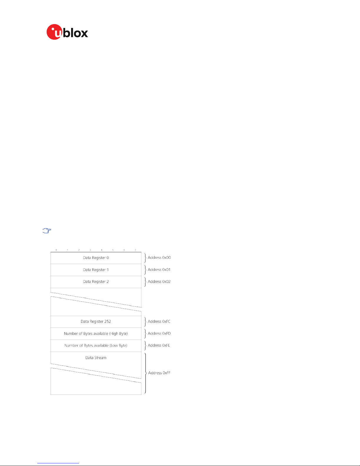
The DDC interface allows 256 slave registers to be addressed. As shown in Figure 13 only three of
these are currently implemented. The data registers 0 to 252, at addresses 0x00 to 0xFC, each 1
byte in size, contain information to be defined later - the result of reading them is undefined. The
currently available number of bytes in the message stream can be read at addresses 0xFD and
0xFE. The register at address 0xFF allows the data stream to be read. If there is no data awaiting
transmission from the receiver, then this register will deliver the value 0xFF, which cannot be the
first byte of a valid message. If message data is ready for transmission, then successive reads of
register 0xff will deliver the waiting message data.
The registers 0x00 to 0xFC are reserved for future use and may be defined in a later
firmware release. Do not use them, as they don't provide any meaningful data.
Figure 13: DDC register layout
UBX-19005590 - R01
3 Receiver functionality Page 31 of 80
Advance Information
Page 32

ZED-F9T-Integration Manual
3.3.11.5.1.1 Read access forms
There are two forms of DDC read transfer. The "random access" form includes a slave register
address and thus allows any register to be read. The second "current address" form omits the
register address. If this second form is used, then an address pointer in the receiver is used to
determine which register to read. This address pointer will increment after each read unless it
is already pointing at register 0xFF, the highest addressable register, in which case it remains
unaltered. The initial value of this address pointer at start-up is 0xFF, so by default all current
address reads will repeatedly read register 0xFF and receive the next byte of message data (or 0xFF
if no message data is waiting). Figure 14 shows the format of the random access form of the request.
Following the start condition from the master, the 7-bit device address and the RW bit (which is a
logic low for write access) are clocked onto the bus by the master transmitter. The receiver answers
with an acknowledge (logic low) to indicate that it recognizes the address. Next, the 8-bit address
of the register to be read must be written to the bus. Following the receiver's acknowledgement,
the master again triggers a start condition and writes the device address, but this time the RW bit
is a logic high to initiate the read access. Now, the master can read 1 to N bytes from the receiver,
generating a not-acknowledge and a stop condition after the last byte being read.
Figure 14: DDC random read access
The format of the current address read request is:
Figure 15: DDC current address read access
UBX-19005590 - R01
3 Receiver functionality Page 32 of 80
Advance Information
Page 33

ZED-F9T-Integration Manual
3.3.11.5.2 Write access
The receiver does not provide any write access except for writing UBX and NMEA messages to the
receiver, such as configuration or aiding data. Therefore, the register set mentioned in section Read
Access is not writeable. Following the start condition from the master, the 7-bit device address and
the RW bit (which is a logic low for write access) are clocked onto the bus by the master transmitter.
The receiver answers with an acknowledge (logic low) to indicate that it is responsible for the given
address. Now, the master can write 2 to N bytes to the receiver, generating a stop condition after the
last byte being written. The number of data bytes must be at least 2 to properly distinguish from
the write access to set the address counter in random read accesses.
Figure 16: DDC write access
3.4 Multiple GNSS assistance (MGA)
The u-blox MGA services provide a proprietary implementation of an A-GNSS protocol compatible
with u-blox GNSS receivers. When a client device makes an MGA request, the service responds
with the requested data using UBX protocol messages. These messages are ready for direct
transmission to the receiver communication port without requiring any modification by the client.
AssistNow Online optionally provides satellite ephemerides, health information and time aiding data
suitable for GNSS receiver systems with direct internet access.
The data downloaded from the service is organized by date and encoded into a sequence of UBX
MGA messages.
The ZED-F9T supports AssistNow Online only.
3.4.1 AssistNow Online
AssistNow Online is u-blox's end-to-end Assisted GNSS (A-GNSS) solution for receivers that have
access to the Internet. Data supplied by the AssistNow Online Service can be directly uploaded to
a u-blox receiver in order to substantially reduce time to first fix (TTFF), even under poor signal
conditions. The system works by collecting data such as ephemeris and almanac from the satellites
through u-blox's "Global Reference Network" of receivers and providing this data to customers in a
convenient form that can be forwarded directly to u-blox receivers.
The AssistNow Online Service uses a simple, stateless, HTTP interface. Therefore, it works on all
standard mobile communication networks that support Internet access, including GPRS, UMTS and
Wireless LAN. No special arrangements need to be made with mobile network operators to enable
AssistNow Online.
UBX-19005590 - R01
3 Receiver functionality Page 33 of 80
Advance Information
Page 34

ZED-F9T-Integration Manual
Figure 17: MGA architecture
The data returned by the AssistNow Online Service is a sequence of UBX-MGA messages, starting
with an estimate of the current time in the form of a UBX-MGA-INI-TIME_UTC message.
AssistNow Online currently supports GPS, GLONASS, BeiDou, Galileo, and QZSS.
Customers may choose to use third party sources of assistance data instead of using
the AssistNow Online Service. Customers choosing this option will need to ensure that
the data is converted from the format used by the third party source to the appropriate
MGA messages. However, it is important to ensure that the receiver has an estimate of the
current time before it processes any other assistance data. For this reason, it is strongly
recommended to send a UBX-MGA-INITIME_UTC or UBX-MGA-INI-TIME_GNSS as the first
message of any assistance.
3.4.2 Host software
As u-blox receivers have no means to connect directly with the Internet, the AssistNow Online
system can only work if the host system that contains the receiver can connect to the Internet,
download the data from the AssistNow Online Service and forward it on to the receiver. In the
simplest case that may involve fetching the data from the AssistNow Online Service (by means of a
single HTTP or HTTPS GET request), and sending the resulting data to the receiver.
Depending on the circumstances, it may be beneficial for the host software to include:
• Creating an appropriate UBX-MGA-INI-TIME_UTC message to deliver a better estimation of
the current time to the receiver, especially if the host system has a very good estimation of the
current time and can deliver a time pulse to one of the receiver's EXTINT pins.
• Enable and use flow control to prevent loss of data due to buffer overflow in the receiver.
u-blox provides the source code for an example library, called libMGA, that provides all of the
functionality we expect in most host software.
3.4.3 AssistNow Online sequence
A typical sequence of use of the AssistNow Online Service comprises the following steps:
• Power-up the u-blox receiver.
• Request data from the AssistNow Online Service.
UBX-19005590 - R01
3 Receiver functionality Page 34 of 80
Advance Information
Page 35

ZED-F9T-Integration Manual
• Optionally send UBX-MGA-INI-TIME_UTC followed by hardware time synchronization pulse if
hardware time synchronization is required.
• Send the UBX messages obtained from the AssistNow Online Service to the receiver.
3.4.4 Flow control
u-blox receivers aim to process incoming messages as quickly as possible, but there will always be
a small delay in processing each message. Uploading assistance data to the receiver can involve
sending as many as one hundred of individual messages to the receiver, one after the other. If the
communication link is fast, and/or the receiver is busy (trying to acquire new signals), it is possible
that the internal buffers will overflow and some messages will be lost. In order to combat this, u-blox
receivers support an optional flow control mechanism for assistance.
Flow control is activated by using the CFG-NAVSPG-ACKAIDING configuration item. As a result the
receiver will issue an acknowledgment message (ACK) for each assistance message it successfully
receives. The host software can examine these acknowledgments to establish whether there were
any problems with the data sent to the receiver and deduce (by the lack of acknowledgment) if any
messages have been lost. It may then be appropriate to resend some of the assistance messages.
The simplest way to implement flow control would be to send one UBX-MGA message at a time,
waiting for the acknowledgment, before sending the next. However, such a strategy is likely to
introduce significant delays into the whole assistance process. The best strategy will depend on
the amount of assistance data being sent and the nature of the communications link (e.g. baud
rate of serial link). u-blox recommends that when customers are developing their host software they
start by sending all assistance messages and then analyze the resulting acknowledgments to see if
there are any loses of messages. Adding small delays during the transmission may be a simple but
effective way to avoid loss of data.
3.4.5 Authorization
The AssistNow Online Service is only available for use by u-blox customers. In order to use the
services, customers will need to obtain an authorization token from u-blox. This token must be
supplied as a parameter whenever a request is made to either service.
3.4.6 Service parameters
The information exchange with the AssistNow Online Service is based on the HTTPS protocol. Upon
reception of an HTTPS GET request, the server will respond with the required messages in binary
format or with an error string in text format. After delivery of all data, the server will terminate the
connection.
The HTTPS GET request from the client to the server should contain a standard HTTPS query string
in the request URL. The query string consists of a set of "key=value" parameters in the following
form:
key=value;key=value;key=value;
The following rules apply:
• The order of keys is important.
• Keys and values are case sensitive.
• Keys and values must be separated by an "equal" character ("=").
• Key/value pairs must be separated by semicolons (";").
• If a value contains a list, each item in the list must be separated by a comma (",").
The following table describes the keys that are supported:
UBX-19005590 - R01
3 Receiver functionality Page 35 of 80
Advance Information
Page 36

ZED-F9T-Integration Manual
Key name Unit/range Optional Description
token String Mandatory The authorization token supplied by u-blox when a client registers to use the
service.
gnss String Mandatory A comma separated list of the GNSS for which data should be returned. Valid GNSS
are: gps, gal, glo, bds and qzss (case sensitive).
datatype String Mandatory A comma separated list of the data types required by the client. Valid data types
are: eph, alm, aux and pos. Time data is always returned for each request. If the
value of this parameter is an empty string, only time data will be returned.
lat Numeric
[degrees]
Optional Approximate user latitude in WGS 84 expressed in degrees and fractional degrees.
Must be in range -90 to 90. Example: lat=47.2.
lon Numeric
[degrees]
Optional Approximate user longitude in WGS 84 expressed in degrees and fractional
degrees. Must be in range -180 to 180. Example: lon=8.55.
alt Numeric
[meters]
Optional Approximate user altitude above WGS 84 Ellipsoid. If this value is not provided, the
server assumes an altitude of 0 meters. Must be in range -1000 to 50000.
pacc Numeric
[meters]
Optional Approximate accuracy of submitted position (see position parameters note below).
If this value is not provided, the server assumes an accuracy of 300km. Must be in
range 0 to 6000000.
tacc Numeric
[seconds]
Optional The timing accuracy (see time parameters note below). If this value is not provided,
the server assumes an accuracy of 10 seconds. Must be in range 0 to 3600.
latency Numeric
[seconds]
Optional Typical latency between the time the server receives the request, and the time
when the assistance data arrives at the u-blox receiver. The server can use this
value to correct the time being transmitted to the client. If this value is not
provided, the server assumes a latency of 0. Must be in range 0 to 3600.
filteronpos (no value
required)
Optional If present, the ephemeris data returned to the client will only contain data for the
satellites which are likely to be visible from the approximate position provided by
the lat, lon, alt and pacc parameters. If the lat and lon parameters are not provided
the service will return an error.
filteronsv String Optional A comma separated list of u-blox gnssId:svId pairs. The ephemeris data returned to
the client will only contain data for the listed satellites.
Table 18: AssistNow Online parameter keys
Thus, as an example, a valid parameter string would be:
token=XXXXXXXXXXXXXXXXXXXXXX;gnss=gps,qzss;datatype=eph,pos,aux;lat=47.28;lon=8.56;pacc=1000
3.4.6.1 Position parameters (lat, lon, alt and pacc)
The position parameters (lat, lon, alt and pacc) are used by the server for two purposes:
• If the filteronpos parameter is provided, the server determines the currently visible satellites at
the user position, and only sends the ephemeris data of those satellites which should be in view
at the location of the user. This reduces bandwidth requirements. In this case the "pacc" value
is taken into account, meaning that the server will return all SVs visible in the given uncertainty
region.
• If the datatype "pos" is requested, the server will return the position and accuracy in the
response data. When this data is supplied to the u-blox receiver, depending on the accuracy
of the provided data, the receiver can then choose to select a better startup strategy. For
example, if the position is accurate to 100km or better, the u-blox receiver will choose to go
for a more optimistic startup strategy. This will result in quicker startup time. The receiver will
decide which strategy to choose, depending on the "pacc" parameter. If the submitted user
position is less accurate than what is being specified with the "pacc" parameter, then the user
will experience prolonged or even failed startups.
3.4.6.2 Time parameters (tacc and latency)
Time data is always returned with each request. The time data refers to the time at which the
response leaves the server, corrected by an optional latency value. This time data provided by the
service is accurate to approximately 10 ms but by default the time accuracy is indicated to be +/-10
UBX-19005590 - R01
3 Receiver functionality Page 36 of 80
Advance Information
Page 37

ZED-F9T-Integration Manual
seconds in order to account for network latency and any time between the client receiving the data
and it being provided to the receiver.
If both the network latency and the client latency can safely be assumed to be very low (or are
known), the client can choose to set the accuracy of the time message (tacc) to a much smaller
value (e.g. 0.5 s). This will result in a faster TTFF. The latency can also be adjusted as appropriate.
However, these fields should be used with caution: if the time accuracy is not correct when the time
data reaches the receiver, the receiver may experience prolonged or even failed start-ups.
For optimal results, the client should establish an accurate sense of time itself (e.g. by calibrating
its system clock using a local NTP service) and then modify the time data received from the service
as appropriate.
3.4.7 Multiple servers
u-blox has designed and implemented the AssistNow Online Service in a way that should provide
very high reliability. Nonetheless, there will be rare occasions when a server is not available (e.g. due
to failure or some form of maintenance activity). In order to protect customers against the impact
of such outages, u-blox runs at least two instances of the AssistNow Online Service on independent
machines. Customers have a choice of requesting assistance data from any of these servers, as all
will provide the same information. However, should one fail for whatever reason, it is highly unlikely
that the other server(s) will also be unavailable. Therefore customers requiring the best possible
availability are recommended to implement a scheme where they direct their requests to a chosen
server, but, if that server fails to respond, have a fallback mechanism to use another server instead.
3.5 Clocks and time
This section introduces and explains the concepts of receiver clocks and time bases.
3.5.1 Receiver local time
The receiver is dependent on a local oscillator for both the operation of its radio parts and also for
timing within its signal processing. No matter what nominal frequency the local oscillator has, u-blox
receivers subdivide the oscillator signal to provide a 1 kHz reference clock signal, which is used to
drive many of the receiver's processes. In particular, the measurement of satellite signals is arranged
to be synchronized with the "ticking" of this 1 kHz clock signal.
When the receiver first starts, it has no information about how these clock ticks relate to other time
systems; it can only count time in 1 millisecond steps. However, as the receiver derives information
from the satellites it is tracking or from aiding messages, it estimates the time that each 1 kHz clock
tick takes in the time-base of the relevant GNSS system. In previous generations of u-blox receivers
this was always the GPS time-base, but for this generation it could be GPS, GLONASS, Galileo, or
BeiDou. This estimate of GNSS time based on the local 1 kHz clock is called receiver local time.
As receiver local time is a mapping of the local 1 kHz reference onto a GNSS time-base, it
may experience occasional discontinuities, especially when the receiver first starts up and the
information it has about the time-base is changing. Indeed, after a cold start, the receiver local
time will initially indicate the length of time that the receiver has been running. However, when the
receiver obtains some credible timing information from a satellite or aiding message, it will jump to
an estimate of GNSS time.
3.5.2 Navigation epochs
Each navigation solution is triggered by the tick of the 1 kHz clock nearest to the desired navigation
solution time. This tick is referred to as a navigation epoch. If the navigation solution attempt is
successful, one of the results is an accurate measurement of time in the time-base of the chosen
GNSS system, called GNSS system time. The difference between the calculated GNSS system time
UBX-19005590 - R01
3 Receiver functionality Page 37 of 80
Advance Information
Page 38

ZED-F9T-Integration Manual
and receiver local time is called the clock bias (and the clock drift is the rate at which this bias is
changing).
In practice the receiver's local oscillator will not be as stable as the atomic clocks to which GNSS
systems are referenced and consequently clock bias will tend to accumulate. However, when
selecting the next navigation epoch, the receiver will always try to use the 1 kHz clock tick which it
estimates to be closest to the desired fix period as measured in GNSS system time. Consequently
the number of 1 kHz clock ticks between fixes will occasionally vary (so when producing one fix per
second, there will normally be 1000 clock ticks between fixes, but sometimes, to correct drift away
from GNSS system time, there will be 999 or 1001).
The GNSS system time calculated in the navigation solution is always converted to a time in both
the GPS and UTC time-bases for output.
Clearly when the receiver has chosen to use the GPS time-base for its GNSS system time, conversion
to GPS time requires no work at all, but conversion to UTC requires knowledge of the number of
leap seconds since GPS time started (and other minor correction terms). The relevant GPS to UTC
conversion parameters are transmitted periodically (every 12.5 minutes) by GPS satellites, but can
also be supplied to the receiver via the UBX-MGA-GPS-UTC aiding message. By contrast when the
receiver has chosen to use the GLONASS time-base as its GNSS system time, conversion to GPS
time is more difficult as it requires knowledge of the difference between the two time-bases, but
conversion to UTC is easier (as GLONASS time is closely linked to UTC).
Where insufficient information is available for the receiver to perform any of these time-base
conversions precisely, pre-defined default offsets are used. Consequently plausible times are nearly
always generated, but they may be wrong by a few seconds (especially shortly after receiver start).
Depending on the configuration of the receiver, such "invalid" times may well be output, but with
flags indicating their state (e.g. the "valid" flags in UBX-NAV-PVT).
u-blox receivers employ multiple GNSS system times and/or receiver local times (in order to
support multiple GNSS systems concurrently), so users should not rely on UBX messages
that report GNSS system time or receiver local time being supported in future. It is therefore
recommended to give preference to those messages that report UTC time.
3.5.3 iTOW timestamps
All the main UBX-NAV messages (and some other messages) contain an iTOW field which indicates
the GPS time at which the navigation epoch occurred. Messages with the same iTOW value can be
assumed to have come from the same navigation solution.
Note that iTOW values may not be valid (i.e. they may have been generated with insufficient
conversion data) and therefore it is not recommended to use the iTOW field for any other purpose.
The original designers of GPS chose to express time/date as an integer week number
(starting with the first full week in January 1980) and a time of week (often abbreviated
to TOW) expressed in seconds. Manipulating time/date in this form is far easier for digital
systems than the more "conventional" year/month/day, hour/minute/second representation.
Consequently, most GNSS receivers use this representation internally, only converting
to a more "conventional form" at external interfaces. The iTOW field is the most obvious
externally visible consequence of this internal representation.
If reliable absolute time information is required, users are recommended to use the UBX-NAV-PVT
navigation solution message which also contains additional fields that indicate the validity (and
accuracy in UBX-NAV-PVT) of the calculated times (see also the GNSS times section below for
further messages containing time information).
3.5.4 GNSS times
Each GNSS has its own time reference for which detailed and reliable information is provided in the
messages listed in the table below.
UBX-19005590 - R01
3 Receiver functionality Page 38 of 80
Advance Information
Page 39

ZED-F9T-Integration Manual
Time reference Message
GPS time UBX-NAV-TIMEGPS
BeiDou time UBX-NAV-TIMEBDS
GLONASS time UBX-NAV-TIMEGLO
Galileo time UBX-NAV-TIMEGAL
UTC time UBX-NAV-TIMEUTC
Table 19: GNSS times
3.5.5 Time validity
Information about the validity of the time solution is given in the following form:
•
Time validity: Information about time validity is provided in the valid flags (e.g. validDate
and validTime flags in the UBX-NAV-PVT message). If these flags are set, the time is known
and considered as valid for being used. These flags can be found in the GNSS times table in the
GNSS times section above as well as in the UBX-NAV-PVT message.
• Time validity confirmation: Information about confirmed validity is provided in the
confirmedDate and confirmedTime flags in the UBX-NAV-PVT message. If these flags are
set, the time validity could be confirmed by using an additional independent source, meaning
that the probability of the time to be correct is very high. Note that information about time
validity confirmation is only available if the confirmedAvai bit in the UBX-NAV-PVT message
is set.
validDate means that the receiver has knowledge of the current date. However, it must
be noted that this date might be wrong for various reasons. Only when the confirmedDate
flag is set, the probability of the incorrect date information drops significantly.
validTime means that the receiver has knowledge of the current time. However, it must
be noted that this time might be wrong for various reasons. Only when the confirmedTime
flag is set, the probability of incorrect time information drops significantly.
fullyResolved means that the UTC time is known without full seconds ambiguity. When
deriving UTC time from GNSS time the number of leap seconds must be known, with the
exception of GLONASS. It might take several minutes to obtain such information from the
GNSS payload. When the one second ambiguity has not been resolved, the time accuracy is
usually in the range of ~20s.
3.5.6 UTC representation
UTC time is used in many NMEA and UBX messages. In NMEA messages it is always reported
rounded to the nearest hundredth of a second. Consequently, it is normally reported with two
decimal places (e.g. 124923.52). What is more, although compatibility mode (selected using CFGNMEA-COMPAT) requires three decimal places, rounding to the nearest hundredth of a second
remains, so the extra digit is always 0.
UTC time is also reported within some UBX messages, such as UBX-NAV-TIMEUTC and UBX-NAVPVT. In these messages date and time are separated into seven distinct integer fields. Six of
these (year, month, day, hour, min and sec) have fairly obvious meanings and are all guaranteed to
match the corresponding values in NMEA messages generated by the same navigation epoch. This
facilitates simple synchronization between associated UBX and NMEA messages.
The seventh field is called nano and it contains the number of nanoseconds by which the rest of
the time and date fields need to be corrected to get the precise time. So, for example, the UTC time
12:49:23.521 would be reported as: hour: 12, min: 49, sec: 23, nano: 521000000.
UBX-19005590 - R01
3 Receiver functionality Page 39 of 80
Advance Information
Page 40

ZED-F9T-Integration Manual
It is however important to note that the first six fields are the result of rounding to the nearest
hundredth of a second. Consequently the nano value can range from -5000000 (i.e. -5 ms) to
+994999999 (i.e. nearly 995 ms).
When the nano field is negative, the number of seconds (and maybe minutes, hours, days, months
or even years) will have been rounded up. Therefore, some or all of them will need to be adjusted in
order to get the correct time and date. Thus in an extreme example, the UTC time 23:59:59.9993
on 31st December 2011 would be reported as: year: 2012, month: 1, day: 1, hour: 0, min: 0, sec: 0,
nano: -700000.
Of course, if a resolution of one hundredth of a second is adequate, negative nano values can simply
be rounded up to 0 and effectively ignored.
Which master clock the UTC time is referenced to is output in the message UBX-NAV-TIMEUTC.
The preferred variant of UTC time can be specified using CFG-NAVSPG-UTCSTANDARD
configuration item.
UTC time is derived directly from the GNSS time scale, which in turn is realized by the
receiver's navigation solution. The derivation of the UTC time includes various parameters
that are having their own errors which are then added on top of receiver's navigation solution
error. Because of that, UTC time is not recommended to be used in high accuracy timing
applications. The best timing accuracy and stability is achieved when receiver outputs GNSS
time scale rather than UTC.
3.5.7 Leap seconds
Occasionally it is decided (by one of the international time keeping bodies) that, due to the slightly
uneven spin rate of the Earth, UTC has moved sufficiently out of alignment with mean solar time (i.e.
the Sun no longer appears directly overhead at 0 longitude at midday). A "leap second" is therefore
announced to bring UTC back into close alignment. This normally involves adding an extra second
to the last minute of the year, but it can also happen on 30th June. When this happens UTC clocks
are expected to go from 23:59:59 to 23:59:60 and only then on to 00:00:00.
It is also theoretically possible to have a negative leap second, in which case there will only be 59
seconds in a minute and 23:59:58 will be followed by 00:00:00.
u-blox receivers are designed to handle leap seconds in their UTC output and consequently users
processing UTC times from either NMEA and UBX messages should be prepared to handle minutes
that are either 59 or 61 seconds long.
Leap second information can be polled from the u-blox receiver with the message UBX-NAV-TIMELS.
3.5.8 Real time clock
u-blox receivers contain circuitry to support a real time clock, which (if correctly fitted and powered)
keeps time while the receiver is otherwise powered off. When the receiver powers up, it attempts to
use the real time clock to initialize receiver local time and in most cases this leads to appreciably
faster first fixes.
3.5.9 Date
All GNSS frequently transmit information about the current time within their data message. In most
cases, this is a time of week (often abbreviated to TOW), which indicates the elapsed number of
seconds since the start of the week (midnight Saturday/Sunday). In order to map this to a full date,
it is necessary to know which week and so the GNSS also transmit a week number, typically every
30 seconds. Unfortunately the GPS L1C/A data message was designed in a way that only allows the
bottom 10 bits of the week number to be transmitted. This is not sufficient to yield a completely
unambiguous date as every 1024 weeks (a bit less than 20 years), the transmitted week number
UBX-19005590 - R01
3 Receiver functionality Page 40 of 80
Advance Information
Page 41

ZED-F9T-Integration Manual
value "rolls over" back to zero. Consequently, GPS L1 receivers can't tell the difference between, for
example, 1980, 1999 or 2019 etc.
Fortunately, although BeiDou and Galileo have similar representations of time, they transmit
sufficient bits for the week number to be unambiguous for the foreseeable future (the first
ambiguity will be in 2078 for Galileo and not until 2163 for BeiDou). GLONASS has a different
structure, based on a time of day, but again transmits sufficient information to avoid any ambiguity
during the expected lifetime of the system (the first ambiguous date will be in 2124). Therefore, ublox 9 receivers using Protocol Version 24 and above regard the date information transmitted by
GLONASS, BeiDou and Galileo to be unambiguous and, where necessary, use this to resolve any
ambiguity in the GPS date.
Customers attaching u-blox receivers to simulators should be aware that GPS time is
referenced to 6th January 1980, GLONASS to 1st January 1996, Galileo to 22nd August
1999 and BeiDou to 1st January 2006; the receiver cannot be expected to work reliably with
signals that appear to come from before these dates.
3.5.9.1 GPS-only date resolution
In circumstances where only GPS L1C/A signals are available and for receivers with earlier firmware
versions, the receiver establishes the date by assuming that all week numbers must be at least
as large as a reference rollover week number. This reference rollover week number is hard-coded
at compile time and is normally set a few weeks before the software is completed, but it can be
overridden by CFG-NAVSPG-WKNROLLOVER configuration item to any value the user wishes.
The following example illustrates how this works: Assume that the reference rollover week number
set in the firmware at compile time is 1524 (which corresponds to a week in calendar year 2009,
but would be transmitted by the satellites as 500). In this case, if the receiver sees transmissions
containing week numbers in the range 500 ... 1023, these will be interpreted as week numbers
1524 ... 2047 (calendar year 2009 ... 2019), whereas transmissions with week numbers from 0 to
499 are interpreted as week numbers 2048 ... 2547 (calendar year 2019 ... 2028).
It is important to set the reference rollover week number appropriately when supplying ublox receivers with simulated signals, especially when the scenarios are in the past.
3.6 Timing functionality
The ZED-F9T provides precision time references used by remote or distributed wireless
communication, industrial, financial, and power distribution equipment.
3.6.1 Time pulse
3.6.1.1 Introduction
The ZED-F9T receiver includes two time pulse outputs with configurable duration and frequency.
The time pulse function can be configured using the CFG-TP-* configuration group for the desired
time pulse; TP1 or TP2. Note that TP1 refers to pin 53 (Timepulse) and TP2 to pin 54 (Timepulse
2). The UBX-TIM-TP message provides time information for the next pulse, time source and the
quantization error of the output pin.
UBX-19005590 - R01
3 Receiver functionality Page 41 of 80
Advance Information
Page 42

ZED-F9T-Integration Manual
Figure 18: Timepulse
3.6.1.2 Recommendations
• The time pulse can be aligned to a wide variety of GNSS times or to variants of UTC derived
from them (see the chapter on time bases). However, it is strongly recommended that the
choice of time base is aligned with the available GNSS signals (so to produce GPS time or
UTC(USNO), ensure GPS signals are available, and for GLONASS time or UTC(SU) ensure the
presence GLONASS signals). This will involve coordinating that the setting of CFG-SIGNAL-*
configuration group with the choice of time pulse time base.
• When using time pulse for precision timing applications it is recommended to calibrate the
antenna cable delay against a reference timing source.
•
In order to get the best timing accuracy with the antenna, a fixed and accurate position is
needed.
• If relative time accuracy between multiple receivers is required, do not mix receivers of different
product families. If this is required, the receivers must be calibrated accordingly, by setting
cable delay and user delay.
• The recommended configuration when using the UBX-TIM-TP message is to set both the
measurement rate (CFG-RATE-MEAS) and the time pulse frequency (CFG-TP-*) to 1Hz.
Since the rate of UBX-TIM-TP is bound to 1 Hz, more than one UBX-TIM-TP message can
appear between two pulses if the time pulse frequency is set lower than 1 Hz. In this case all
UBX-TIM-TP messages in between a time pulse T1 and T2 belong to T2 and the last UBXTIM-TP before T2 reports the most accurate quantization error. In general, if the time pulse
rate is not configured to 1 Hz, there will not be a single UBX-TIM-TP message for each time
pulse.
SBAS is not recommended to use for timing applications.
The sequential order of the signal present at the TIMEPULSE pin and the respective output message
for the simple case of 1 pulse per second (1PPS) is shown in the following figure.
UBX-19005590 - R01
3 Receiver functionality Page 42 of 80
Advance Information
Page 43

ZED-F9T-Integration Manual
Figure 19: Timepulse and TIM-TP
3.6.1.3 GNSS time bases
GNSS receivers must handle a variety of different time bases as each GNSS has its own reference
system time. What is more, although each GNSS provides a model for converting their system time
into UTC, they all support a slightly different variant of UTC. So, for example, GPS supports a variant
of UTC as defined by the US National Observatory, while BeiDou uses UTC from the National Time
Service Center, China (NTSC). While the different UTC variants are normally closely aligned, they
can differ by as much as a few hundreds of nanoseconds.
Although u-blox receivers can combine a variety of different GNSS times internally, the user must
choose a single type of GNSS time and, separately, a single type of UTC for input (on EXTINTs) and
output (via the Time Pulse) and the parameters reported in corresponding messages.
The CFG-TP-* configuration group allows the user to choose between any of the supported GNSS
(GPS, GLONASS, BeiDou, etc) times and UTC. Also, the CFG-NAVSPG-* configuration group allows
the user to select which variant of UTC the receiver should use. This includes an "automatic"
option which causes the receiver to select an appropriate UTC version itself, based on the GNSS
configuration, using, in order of preference, USNO if GPS is enabled, SU if GLONASS is enabled, NTSC
if BeiDou is enabled and, finally, European if Galileo is enabled.
The receiver will assume that the input time pulse uses the same GNSS time base as specified for
the output using CFG-TP-*. So if the user selects GLONASS time for time pulse output, any time
pulse input must also be aligned to GLONASS time (or to the separately chosen variant of UTC).
Where UTC is selected for time pulse output, any GNSS time pulse input will be assumed to be
aligned to GPS time.
u-blox receivers allow users to choose independently GNSS signals used in the receiver
(using CFG-SIGNAL-*) and the input/output time base (using CFG-TP-*). For example it
is possible to instruct the receiver to use GPS and GLONASS satellite signals to generate
BeiDou time. This practice will compromise time-pulse accuracy if the receiver cannot
measure the timing difference between the constellations directly and is therefore not
recommended.
The information that allows GNSS times to be converted to the associated UTC times is
only transmitted by the GNSS at relatively infrequent periods. For example GPS transmits
UTC(USNO) information only once every 12.5 minutes. Therefore, if a time pulse is
configured to use a variant of UTC time, after a cold start, substantial delays before the
receiver has sufficient information to start outputting the time pulse can be expected.
3.6.1.4 Time pulse configuration
u-blox ZED-F9T receivers provide a time pulse (TIMEPULSE) signal with a configurable pulse period,
pulse length and polarity (rising or falling edge).
UBX-19005590 - R01
3 Receiver functionality Page 43 of 80
Advance Information
Page 44

ZED-F9T-Integration Manual
It is possible to define different signal behavior (i.e. output frequency and pulse length) depending on
whether or not the receiver is locked to a reliable time source. Time pulse signals can be configured
using the configuration group CFG-TP-*.
3.6.1.5 Configuring time pulse with CFG-TP-*
The configuration group CFG-TP-* can be used to change the time pulse settings, and includes the
following parameters defining the pulse:
• timepulse enable - time pulse is active if this bit is set.
• time pulse index - Index of time pulse output pin to be configured. A device with one time pulse
output is configured with index 0.
• antenna cable delay - Signal delay due to the cable between antenna and receiver.
• RF group delay - Signal delay in the RF module of the receiver (read-only).
• pulse frequency/period - Frequency or period time of the pulse when locked mode is not
configured or active.
• pulse frequency/period lock - Frequency or period time of the pulse, as soon as receiver has
calculated a valid time from a received signal. Only used if the corresponding flag is set to use
another setting in locked mode.
• pulse length/ratio - Length or duty cycle of the generated pulse, either specifies a time or ratio
for the pulse to be on/off.
• pulse length/ratio lock - Length or duty cycle of the generated pulse, as soon as receiver has
calculated a valid time from a received signal. Only used if the corresponding flag is set to use
another setting in locked mode.
• user delay - The cable delay from the receiver to the user device plus signal delay of any user
application.
• lock to gps freq - Use frequency gained from GPS signal information rather than local
oscillator's frequency if flag is set.
• lock to gnss freq - Use frequency gained from GNSS signal information rather than local
oscillator's frequency if flag is set.
• locked other setting - If this bit is set, as soon as the receiver can calculate a valid time, the
alternative setting is used. This mode can be used for example to disable time pulse if time is
not locked, or indicate lock with different duty cycles.
• is frequency - Interpret the "Frequency/Period" field as frequency rather than period if flag is
set.
• is length - Interpret the "Length/Ratio" field as length rather than ratio if flag is set.
• align to TOW - If this bit is set, pulses are aligned to the top of a second.
• polarity - If set, the first edge of the pulse is a rising edge (Pulse Mode: Rising).
• grid UTC/GPS - Selection between UTC (0) or GPS (1) timegrid. Also effects the time output by
UBX-TIM-TP message.
• grid UTC/GNSS - Selection between UTC (0), GPS (1), GLONASS (2) and Beidou (3) timegrid.
Also effects the time output by UBX-TIM-TP message.
The maximum pulse length can't exceed the pulse period.
Time pulse settings shall be chosen in such a way, that neither the high nor the low period
of the output is less than 50 ns (except when disabling it completely), otherwise pulses can
be lost.
3.6.1.5.1 Example
The example below shows the 1PPS TIMEPULSE signal generated on the time pulse output
according to the specific parameters of the CFG-TP-* configuration group:
• CFG-TP-TP1_ENA = 1
• CFG-TP-PERIOD_TP1 = 100 000 µs
UBX-19005590 - R01
3 Receiver functionality Page 44 of 80
Advance Information
Page 45

ZED-F9T-Integration Manual
• CFG-TP-LEN_TP1 = 100 000 µs
• CFG-TP-TIMEGRID_TP1 = 1 (GPS)
• CFG-TP-PULSE_LENGTH_DEF = 0 (Period)
• CFG-TP-ALIGN_TO_TOW_TP1 = 1
• CFG-TP-USE_LOCKED_TP1 = 1
• CFG-TP-POL_TP1 = 1
• CFG-TP-PERIOD_LOCK_TP1 = 100 000 µs
• CFG-TP-LEN_LOCK_TP1 = 100 000 µs
The 1 Hz output is maintained whether or not the receiver is locked to GPS time. The alignment to
TOW can only be maintained when GPS time is locked.
Figure 20: Time pulse signal with the example parameters
3.6.2 Timemark
The receiver can be used to provide an accurate measurement of the time at which a pulse was
detected on the external interrupt pin. The reference time can be chosen by setting the time source
parameter to UTC, GPS, GLONASS, BeiDou, Galileo or local time in the CFG-TP-* configuration group.
The UTC standard can be set in the CFG-NAVSPG-* configuration group. The delay figures defined
with CFG-TP-* are also applied to the results output in the UBX-TIM-TM2 message.
A UBX-TIM-TM2 message is output at the next epoch if
• The UBX-TIM-TM2 message is enabled, or
• A rising or falling edge was triggered since last epoch on one of the EXTINT channels.
The UBX-TIM-TM2 messages includes the time of the last timemark, new rising/falling edge
indicator, time source, validity, number of marks and a quantization error. The timemark is triggered
continuously.
Only the last rising and falling edge detected between two epochs is reported since the
output rate of the UBX-TIM-TM2 message corresponds to the measurement rate configured
with CFG-RATE-MEAS (see Figure 21 below).
UBX-19005590 - R01
3 Receiver functionality Page 45 of 80
Advance Information
Page 46

ZED-F9T-Integration Manual
Figure 21: Timemark
3.7 Security (operating, monitoring and maintaining)
A host application should be designed to monitor the various security indicators and provide the
information to the user.
3.7.1 Receiver status monitoring
Messages in the UBX class UBX-MON are used to report the status of the parts of the embedded
computer sub-system that are not GNSS specific.
The main purposes are:
• Hardware and software versions, using UBX-MON-VER.
• Status of the communications input/output system, using UBX-MON-COMMS.
• Status of various hardware sections with UBX-MON-HW3 and UBX-MON-RF.
3.7.1.1 Input/output system monitoring
The I/O system is a GNSS-internal layer where all data input- and output capabilities (such as UART,
DDC, SPI, USB) of the GNSS receiver are combined. Each communications task has buffers assigned,
where data are queued. For data originating at the receiver, to be communicated over one or multiple
communications queues, the UBX-MON-COMMS message can be used to monitor the status of the
queues. This message shows the current and maximum buffer usage, as well as error conditions.
UBX-19005590 - R01
3 Receiver functionality Page 46 of 80
Advance Information
Page 47

ZED-F9T-Integration Manual
If the amount of data configured is too much for a certain port's bandwidth (e.g. all UBX
messages output on a UART port with a baud rate of 9600), the buffer will fill up. Once the
buffer space is exceeded, new messages to be sent will be dropped.
Inbound data to the GNSS receiver are placed in buffers. Usage of these buffers can be monitored
through the UBX-MON-COMMS message. Further, as data are then parsed within the receiver (e.g.
to separate UBX and NMEA data), the UBX-MON-COMMS message can be used. This message
shows (for each port and protocol) how many messages were successfully received. It also shows (for
each port) how many bytes were discarded because they were not in any of the supported protocol
framings.
3.7.1.2 Jamming/interference indicator / cw jamming monitoring
The field jamInd of the UBX-MON-RF message can be used as an indicator for continuous
wave (narrow-band) jammers/interference only. The interpretation of the value depends on the
application. It is necessary to run the receiver in an unjammed environment to determine an
appropriate value for the unjammed case. If the value rises significantly above this threshold, this
indicates that a continuous wave jammer is present.
This indicator is always enabled.
The indicator is reporting any currently detected narrow-band interference over all currently
configured signal bands.
3.7.1.3 Jamming/interference monitor (ITFM) / broadband interference monitoring
The field flags of the UBX-MON-RF message can be used as an indicator for both broadband and
continuous wave (CW) jammers/interference. It is independent of the (CW only) jamming indicator
described in Jamming/interference indicator above.
This monitor reports whether jamming has been detected or suspected by the receiver. The receiver
monitors the background noise and looks for significant changes. Normally, with no interference
detected, it will report "OK". If the receiver detects that the noise has risen above a preset threshold,
the receiver reports "Warning". If in addition, there is no current valid fix, the receiver reports
"Critical".
The monitor has four states as shown in the following table:
Value Reported state Description
0 Unknown Jamming/interference monitor not enabled,
uninitialized or antenna disconnected
1 OK no interference detected
2 Warning position ok but interference is visible (above the
thresholds)
3 Critical no reliable position fix and interference is visible (above
the thresholds); interference is probable reason why
there is no fix
Table 20: Jamming/interference monitor reported states
The monitor is disabled by default. The monitor is enabled by sending an appropriate CFG-ITFM* configuration group with the CFG-ITFM-ENABLE bit set. In this message it is also possible to
specify the thresholds at which broadband and CW jamming are reported. These thresholds should
be interpreted as the dB level above "normal". It is also possible to specify whether the receiver
expects an active or passive antenna.
The monitor algorithm relies on comparing the currently measured spectrum with a
reference from when a good fix was obtained. Thus the monitor will only function when the
receiver has had at least one (good) first fix, and will report "Unknown" before this time.
UBX-19005590 - R01
3 Receiver functionality Page 47 of 80
Advance Information
Page 48

ZED-F9T-Integration Manual
The monitor is reporting any currently detected interference over all currently configured signal
bands.
3.7.2 Spoofing detection / monitoring
3.7.2.1 Introduction
Spoofing is the process whereby someone tries to forge a GNSS signal with the intention of fooling
the receiver into calculating a different user position than the true one.
The spoofing detection feature monitors the GNSS signals for suspicious patterns indicating that
the receiver is being spoofed. A flag in UBX-NAV-STATUS message (flags2 - spoofDetState) alerts
the user to potential spoofing.
The spoofing detection feature monitors suspicious changes in the GNSS signal indicating external
manipulation. Therefore the detection is only successful when the signal is genuine first and when
the transition to the spoofed signal is being observed directly. When a receiver is started up
to a spoofed signal the detection algorithms will be unable to recognize the spoofing. Also, the
algorithms rely on availability of signals from multiple GNSS constellations; the detection does not
work in single GNSS mode.
3.8 u-blox protocol feature descriptions
3.8.1 Broadcast navigation data
This section describes the data reported via UBX-RXM-SFRBX.
The UBX-RXM-SFRBX reports the broadcast navigation data message collected by the receiver
from each tracked signal. When enabled, a separate message is generated every time the receiver
decodes a complete subframe of data from a tracked signal. The data bits are reported, as received,
including preambles and error checking bits as appropriate. However because there is considerable
variation in the data structure of the different GNSS signals, the form of the reported data also
varies. Indeed, although this document uses the term "subframe" generically, it is not strictly the
correct term for all GNSS (e.g. GLONASS has "strings" and Galileo has "pages").
3.8.1.1 Parsing navigation data subframes
Each UBX-RXM-SFRBX message contains a subframe of data bits appropriate for the relevant
GNSS, delivered in a number of 32 bit words, as indicated by numWords field.
Due to the variation in data structure between different GNSS, the most important step in parsing
a UBX-RXMSFRBX message is to identify the form of the data. This should be done by reading
the gnssId field, which indicates which GNSS the data was decoded from. In almost all cases, this
is sufficient to indicate the structure and the following sections are organized by GNSS for that
reason. However, in some cases the identity of the GNSS is not sufficient, and this is described,
where appropriate, in the following sections.
In most cases, the data does not map perfectly into a number of 32 bit words and, consequently,
some of the words reported in UBX-RXM-SFRBX messages contain fields marked as "Pad". These
fields should be ignored and no assumption should be made about their contents.
UBX-RXM-SFRBX messages are only generated when complete subframes are detected by the
receiver and all appropriate parity checks have passed.
Where the parity checking algorithm requires data to be inverted before it is decoded (e.g. GPS
L1C/A), the receiver carries this out before the message output. Therefore, users can process data
directly and do not need to worry about repeating any parity processing.
The meaning of the content of each subframe depends on the sending GNSS and is described in the
relevant Interface Control Documents (ICD).
UBX-19005590 - R01
3 Receiver functionality Page 48 of 80
Advance Information
Page 49

ZED-F9T-Integration Manual
3.8.1.2 GPS
The data structure in the GPS L1C/A and L2C signals is dissimilar and thus the UBX-RXM-SFRBX
message structure differs as well. For the GPS L1C/A and L2C signals it is as follows:
3.8.1.2.1 GPS L1C/A
For GPS L1C/A signals, there is a fairly straightforward mapping between the reported subframe
and the structure of subframe and words described in the GPS ICD. Each subframe comprises ten
data words, which are reported in the same order they are received.
Each word is arranged as follows:
Figure 22: GPS L1C/A subframe word
3.8.1.2.2 GPS L2C
For GPS L2C signals each reported subframe contains the CNAV message as described in the GPS
ICD. The ten words are arranged as follows:
Figure 23: GPS L2C subframe words
3.8.1.3 GLONASS
For GLONASS L1OF and L2OF signals, each reported subframe contains a string as described in the
GLONASS ICD. This string comprises 85 data bits which are reported over three 32 bit words in the
UBX-19005590 - R01
3 Receiver functionality Page 49 of 80
Advance Information
Page 50

ZED-F9T-Integration Manual
UBX-RXM-SFRBX message. Data bits 1 to 8 are always a hamming code, whilst bits 81 to 84 are a
string number and bit 85 is the idle chip, which should always have a value of zero. The meaning of
other bits vary with string and frame number.
The fourth and final 32 bit word in the UBX-RXM-SFRBX message contains frame and superframe
numbers (where available). These values aren't actually transmitted by the SVs, but are deduced by
the receiver and are included to aid decoding of the transmitted data. However, the receiver does
not always know these values, in which case a value of zero is reported.
The four words are arranged as follows:
Figure 24: GLONASS subframe words
In some circumstances, (especially on startup) the receiver may be able to decode data from a
GLONASS SV before it can identify the SV. When this occurs UBX-RXM-SFRBX messages will be
issued with an svId of 255 to indicate "unknown".
3.8.1.4 BeiDou
For BeiDou B1I D1, B1I D2, B2I D1, B2I D2 signals, there is a fairly straightforward mapping between
the reported subframe and the structure of subframe and words described in the BeiDou ICD. Each
subframe comprises ten data words, which are reported in the same order they are received.
Each word is arranged as follows:
Figure 25: BeiDou subframe word
UBX-19005590 - R01
3 Receiver functionality Page 50 of 80
Advance Information
Page 51

ZED-F9T-Integration Manual
Note that as the BeiDou data words only comprise 30 bits, the 2 most significant bits in each word
reported by UBX-RXM-SFRBX are padding and should be ignored.
3.8.1.5 Galileo
The Galileo E1 C/B and E5 bl/bQ signals both transmit the I/NAV message but in different
configurations. The UBX-RXM-SFRBX structures for them are as follows.
3.8.1.5.1 Galileo E1 C/B
For Galileo E1 C/B signals, each reported subframe contains a pair of I/NAV pages as described in
the Galileo ICD.
Galileo pages can either be "Nominal" or "Alert" pages. For Nominal pages the eight words are
arranged as follows:
UBX-19005590 - R01
3 Receiver functionality Page 51 of 80
Advance Information
Page 52

ZED-F9T-Integration Manual
Figure 26: Galileo E1 C/B subframe words
3.8.1.5.2 Galileo E5 b1/bQ
For Galileo E5 b1/bQ signals, each reported subframe contains a pair of I/NAV pages as described in
the Galileo ICD. Galileo pages can either be "Nominal" or "Alert" pages. For Nominal pages the eight
words are arranged as follows:
UBX-19005590 - R01
3 Receiver functionality Page 52 of 80
Advance Information
Page 53

ZED-F9T-Integration Manual
Figure 27: Galileo E5 b1/bQ subframe words
Alert pages are reported in very similar manner, but the page type bits will have value 1 and the
structure of the eight words will be slightly different (as indicated by the Galileo ICD).
3.8.1.6 QZSS
The structure of the data delivered by QZSS L1C/A signals is effectively identical to that for GPS
(L1C/A).
Similarly the QZSS L2C signal is effectively identical to the GPS (L2C).
3.8.1.7 Summary
The following table gives a summary of the different data message formats reported by the UBXRXM-SFRBX message:
UBX-19005590 - R01
3 Receiver functionality Page 53 of 80
Advance Information
Page 54

ZED-F9T-Integration Manual
GNSS Signal gnssId sigId numWords period
GPS L1C/A 0 0 10 6s
GPS L2CL 0 3 10 12s
GPS L2CM 0 4 10 12s
Galileo E1 C 2 0 8 2s
Galileo E1 B 2 1 8 2s
Galileo E5 bl 2 5 8 2s
Galileo E5 bQ 2 6 8 2s
BeiDou B1I D1 3 0 10 6s
BeiDou B1I D2 3 1 10 0.6s
BeiDou B2I D1 3 2 10 0.6s
BeiDou B2I D2 3 3 10 0.6s
QZSS L1C/A 5 0 10 6s
QZSS L2CM 5 4 10 12s
QZSS L2CL 5 5 10 12s
GLONASS L1OF 6 0 4 2s
GLONASS L2OF 6 2 4 2s
Table 21: Data message formats reported by UBX-RXM-SFRBX
3.9 Forcing a receiver reset
Typically, in GNSS receivers, one distinguishes between cold, warm, and hot starts, depending on
the type of valid information the receiver has at the time of the restart.
• Cold start: In cold start mode, the receiver has no information from the last position (e.g.
time, velocity, frequency etc.) at startup. Therefore, the receiver must search the full time and
frequency space, and all possible satellite numbers. If a satellite signal is found, it is tracked
to decode the ephemeris (18-36 seconds under strong signal conditions), whereas the other
channels continue to search satellites. Once there is a sufficient number of satellites with
valid ephemeris, the receiver can calculate position and velocity data. Other GNSS receiver
manufacturers call this startup mode Factory startup.
• Warm start: In warm start mode, the receiver has approximate information for time, position,
and coarse satellite position data (Almanac). In this mode, after power-up, the receiver
normally needs to download ephemeris before it can calculate position and velocity data.
As the ephemeris data usually is outdated after 4 hours, the receiver will typically start with
a warm start if it has been powered down for more than 4 hours. In this scenario, several
augmentations are possible. See the section on Multi-GNSS Assistance.
• Hot start: In hot start mode, the receiver was powered down only for a short time (4 hours
or less), so that its ephemeris is still valid. Since the receiver does not need to download
ephemeris again, this is the fastest startup method.
In the UBX-CFG-RST message, one can force the receiver to reset and clear data, in order to see
the effects of maintaining/losing such data between restarts. For this, the UBX-CFG-RST message
offers the navBbrMask field, where hot, warm and cold starts can be initiated, and also other
combinations thereof.
Data stored in flash memory is not cleared by any of the options provided by UBX-CFG-RST.
So, for example, if valid AssistNow Offline data is stored in the flash it is likely to have an
impact on a "cold start".
The reset type can also be specified. This is not related to GNSS, but to the way the software restarts
the system.
UBX-19005590 - R01
3 Receiver functionality Page 54 of 80
Advance Information
Page 55

ZED-F9T-Integration Manual
• Hardware reset uses the on-chip watchdog, in order to electrically reset the chip. This is an
immediate, asynchronous reset. No Stop events are generated.
• Controlled software reset terminates all running processes in an orderly manner and, once
the system is idle, restarts operation, reloads its configuration and starts to acquire and track
GNSS satellites.
• Controlled software reset (GNSS only) only restarts the GNSS tasks, without reinitializing the
full system or reloading any stored configuration.
• Controlled GNSS stop stops all GNSS tasks. The receiver will not be restarted, but will stop any
GNSS related processing.
• Controlled GNSS start starts all GNSS tasks.
UBX-19005590 - R01
3 Receiver functionality Page 55 of 80
Advance Information
Page 56

ZED-F9T-Integration Manual
4 Design
This section provides information to help carry out a successful schematic and PCB design.
Do not load Pin 4 (ANT_DETECT) with a capacitance more than 1 nF.
4.1 Pin assignment
The pin assignment of the ZED-F9T module is shown in Figure 28. The defined configuration of the
PIOs is listed in Table 22.
The ZED-F9T is an LGA package with the I/O on the outside edge and central ground pads.
Figure 28: ZED-F9T pin assignment
Pin No Name I/O Description
1 GND - Ground
2 RF_IN I RF input
3 GND - Ground
4 ANT_DETECT I Active antenna detect - default active high
5 ANT_OFF O External LNA disable - default active high
6 ANT_SHORT_N I Active antenna short detect - default active low.
UBX-19005590 - R01
4 Design Page 56 of 80
Advance Information
Page 57

ZED-F9T-Integration Manual
Pin No Name I/O Description
7 VCC_RF O Voltage for external LNA
8 Reserved - Reserved
9 Reserved - Reserved
10 Reserved - Reserved
11 Reserved - Reserved
12 GND - Ground
13 Reserved - Reserved
14 GND - Ground
15 Reserved - Reserved
16 Reserved - Reserved
17 Reserved - Reserved
18 Reserved - Reserved
19 GEOFENCE_STAT O Geofence status, user defined
20 Reserved - Reserved
21 Reserved - Reserved
22 Reserved - Reserved
23 Reserved - Reserved
24 Reserved - Reserved
25 Reserved - Reserved
26 RXD2 I Correction UART input
27 TXD2 O Correction UART output
28 Reserved - Reserved
29 Reserved - Reserved
30 Reserved - Reserved
31 Reserved - Reserved
32 GND - Ground
33 VCC I Voltage supply
34 VCC I Voltage supply
35 Reserved - Reserved
36 V_BCKP I Backup supply voltage
37 GND - Ground
38 V_USB I USB supply
39 USB_DM I/O USB data
40 USB_DP I/O USB data
41 GND - Ground
42 TXD / SPI_MISO O Host UART output if D_SEL = 1(or open). SPI_MISO if D_SEL = 0
43 RXD / SPI_MOSI I Host UART input if D_SEL = 1(or open). SPI_MOSI if D_SEL = 0
44 SDA / SPI_CS_N I/O DDC Data if D_SEL = 1 (or open). SPI Chip Select if D_SEL = 0
45 SCL / SPI_CLK I/O DDC Clock if D_SEL = 1(or open). SPI Clock if D_SEL = 0
46 Reserved - Reserved
47 D_SEL I Interface select for pins 42-45
48 GND - Ground
49 RESET_N I RESET_N
50 SAFEBOOT_N I SAFEBOOT_N (for future service, updates and reconfiguration, leave OPEN)
UBX-19005590 - R01
4 Design Page 57 of 80
Advance Information
Page 58

ZED-F9T-Integration Manual
Pin No Name I/O Description
51 EXTINT I External Interrupt Pin
52 EXTINT2 I External Interrupt Pin 2
53 TIMEPULSE O Time pulse
54 TIMEPULSE2 O Time pulse 2
Table 22: ZED-F9T pin assignment
4.2 Power supply
The u-blox ZED-F9T module has three power supply pins: VCC, V_BCKP and V_USB.
4.2.1 VCC: Main supply voltage
The VCC pin is connected to the main supply voltage. During operation, the current drawn by the
module can vary by some orders of magnitude. For this reason, it is important that the supply
circuitry be able to support the peak power for a short time (see the ZED-F9T Data sheet [1] for
specification).
The module integrates a DC/DC converter, which allows reduced power consumption.
When switching from backup mode to normal operation or at start-up, u-blox ZED-F9T
modules must charge the internal capacitors in the core domain. In certain situations, this
can result in a significant current draw. For low power applications using backup mode, it is
important that the power supply or low ESR capacitors at the module input can deliver this
current/charge.
To reduce peak current during power on, users can employ an LDO that has an in-built
current limiter
Do not add any series resistance greater than 0.2 Ω to the VCC supply as it will generate
input voltage noise due to dynamic current conditions.
For the ZED-F9T module the equipment must be supplied by an external limited power
source in compliance with the clause 2.5 of the standard IEC 60950-1.
4.2.2 V_BCKP: Backup supply voltage
If the module supply has a power failure, the V_BCKP pin supplies the real-time clock (RTC) and
battery backed RAM (BBR). Use of valid time and the GNSS orbit data at start up will improve the
GNSS performance, as with hot starts and warm starts.
If V_BCKP is not provided, the module performs a cold start at power up.
If a host is connected to ZED-F9T, V_BCKP can be partially emulated by using UBX-UPD-SOS
functionality. BBR data can saved to the host and restored at startup. See Interface Description for
more information.
Avoid high resistance on the V_BCKP line: During the switch from main supply to backup
supply, a short current adjustment peak can cause a high voltage drop on the pin with
possible malfunctions.
If no backup supply voltage is available, connect the V_BCKP pin to VCC.
Allow all I/O including UART and other interfaces to Float/High impedance in HW backup
mode (Battery Back-up connected with VCC removed). See the Interfaces section.
Real-Time Clock (RTC)
The Real-Time Clock (RTC) is driven by a 32 kHz oscillator using an RTC crystal. If VCC is removed
whilst a battery is connected to V_BCKP, most of the receiver is switched off leaving the RTC and
UBX-19005590 - R01
4 Design Page 58 of 80
Advance Information
Page 59

ZED-F9T-Integration Manual
BBR powered. This operating mode is called Hardware Backup Mode which enables time keeping and
all relevant data to be saved to allow a hot or warm start.
4.2.3 ZED-F9T power supply
The ZED-F9T high accuracy timing receiver requires a low noise, low dropout voltage, very low source
impedance power supply of 3.3V typically. No inductors or ferrite beads should be used from LDO
to the module VCC pin. The peak currents need to be taken into account for the source supplying
the LDO for the module.
A power supply fed by 5V is shown in the figure below. This example circuit is intended only for the
module supply.
Figure 29: ZED-F9T power supply
4.3 ZED-F9T minimal design
The minimal electrical circuit for ZED-F9T operation using the UART1 interface is shown in Figure
30 below.
UBX-19005590 - R01
4 Design Page 59 of 80
Advance Information
Page 60

ZED-F9T-Integration Manual
Figure 30: Minimal ZED-F9T design
For a minimal design with the ZED-F9T GNSS modules, the following functions and pins should be
considered:
• Connect the power supply to VCC and V_BCKP.
• If hot or warm start operations are needed, connect a Backup Battery to V_BCKP.
• If USB is not used connect V_USB to ground.
• Ensure an optimal ground connection to all ground pins of the ZED-F9T GNSS modules.
• If antenna bias is required, see ZED-F9T antenna bias section.
4.4 Antenna
u-blox recommends using an active antenna with ZED-F9T.
If an active antenna needs to be implemented in an application case, it is recommended that an
OEM active antenna module be used that meets our specification. To implement the required RF
circuitry and source the required components to meet group delay specification is not a simple
process compared to previous L1 only implementation.
UBX-19005590 - R01
4 Design Page 60 of 80
Advance Information
Page 61

ZED-F9T-Integration Manual
Figure 31: u-blox low cost dual-band antenna internal structure
A suitable ground plane is required for the antenna to achieve good performance.
Location of the antenna is critical to reach the stated performance.
L1 + L2/E5b active antenna required specifications
Parameter Specification
Antenna Type Active antenna
Typical gain 30 dB
Maximum gain 40 dBActive antenna recommendations
Maximum noise figure 2 dB
L1 band antenna gain
1
1559 - 1606 MHz: 3 dBic typ.
L2/E5b band antenna gain
2
1197 - 1249 MHz: 2 dBic typ.
Polarization RHCP
Axial ratio 2 dB max at Zenith
Phase center variation <10 mm over elevation/azimuth
Group delay variation in-band
3
10 ns max @ each GNSS system bandwidth. Note:
Inter-signal requirement 50 ns max.
EMI immunity out-of-band
4
30 V/m
Out-of-band 5 Rejection
40 dB typ
ESD circuit protection 15 kV human body model air discharge
Table 23: Antenna specifications for ZED-F9T modules
The antenna system should include filtering to ensure adequate protection from nearby
transmitters. Care should be taken in the selection of antennas placed close to cellular or Wi-Fi
transmitting antennas.
4.4.1 Antenna bias
Active antennas have an integrated low-noise amplifier that contributes an additional current of
typically 5 to 20 mA to the system's power consumption budget. If customers do not want to make
use of the antenna supervisor function the filtered VCC_RF supply voltage output can supply the
1
Measured with a ground plane d=150 mm
2
Measured with a ground plane d=150 mm
3
GNSS system bandwidths: 1559… 1563 MHz; 1573… 1578 MHz; 1598… 1606 MHz; 1192… 1212 MHz; 1197…
1217 MHz; 1223… 1231 MHz; 1242… 1249 MHz
4
Exception L1 and L2 bands +/- 200 MHz, emphasis on cellular bands
5
GNSS system bandwidths: 1559… 1563 MHz; 1573… 1578 MHz; 1598… 1606 MHz; 1192… 1212 MHz; 1197…
1217 MHz; 1223… 1231 MHz; 1242… 1249 MHz
UBX-19005590 - R01
4 Design Page 61 of 80
Advance Information
Page 62

ZED-F9T-Integration Manual
antenna if the supply voltage of the ZED-F9T module matches the antenna working voltage (e.g.
3.0 V).
A series current limiting resistor is required to prevent short circuits destroying the bias-t
inductor.
The bias-t inductor must be chosen for multi-band operation, a value of 120 nH 5% is
recommended for the recommended Murata L part. It has a self-resonance frequency of 1
GHz and a high impedance (> 500 Ω) at L-band frequencies.
The recommended bias-t inductor (Murata LQW15ANR12J00) has a maximum current capacity of
110 mA. Hence the current is limited to 70 mA at 3.3V using an active limiter in the recommended
circuit shown in Figure 33 below. A 10 Ω resistor (R2) is provided to measure the current. This resistor
power rating must be chosen to ensure reliability in the chosen circuit design.
Figure 32: ZED-F9T antenna bias inductor impedance
A recommended circuit design for an active antenna bias is shown below. This example shows an
external voltage of 3.3V with current limiting as described above. An ESD protection diode should
also be connected to the input as shown.
UBX-19005590 - R01
4 Design Page 62 of 80
Advance Information
Page 63

ZED-F9T-Integration Manual
Figure 33: ZED-F9T reference design for antenna bias
L1: MURATA LQW15A LQW15ANR12J00 0402 120N 5% 0.11A -55/+125C
D1: TYCO, 0.25PF, PESD0402-140 -55/+125C
C2: MURATA GRM0335C1H470JA01 47pF ±5% 50Vdc C0G(EIA) 0±30ppm -55 to 125C
C3: MURATA GRM155R61A104KA01 CER X5R 0402 100N 10% 10V
R2: RES THICK FILM CHIP 1206 10R 5% 0.25W
It is recommended to use active current limiting. If active current limiting is not used, the following
important points covered below need to be taken into account:
Figure 34: ZED-F9T VCC_RF antenna bias
The bias-t inductor and current limiting resistor must be selected to be reliable with a short
on the antenna feed if no active current limiter is used. Our recommended part has a limit of
110 mA, a part with a higher current capability will be needed if the short circuit current is
UBX-19005590 - R01
4 Design Page 63 of 80
Advance Information
Page 64

ZED-F9T-Integration Manual
as described here. This will also be affected by the voltage level of the antenna bias supply
due to power dissipation. The current limit capability of the antenna bias supply needs
to be considered. In the case where the module supplies the voltage via VCC_RF, a higher
value resistor will be needed to ensure the module supply inductor is protected. The current
should be limited to below 150 mA at the module supply voltage under shorting conditions.
In this case a value of 17 Ω or more is required at a module supply of 3V to limit short circuit
current to 150 mA. The DC resistance of the bias-t inductor is assumed to be 1-2 Ω and the
module internal feed inductor is assumed to be 1.2 Ω.
If the VCC_RF voltage does not match with the supply voltage of the active antenna, use a filtered
external supply.
The power dissipation in the resistor and inductor needs to be taken into account based on
the supply voltage and short circuit current. The bias-t inductor current capability and the
bias resistor value need to be calculated as shown above. The supply voltage for the bias-t
and its current capability is part of the calculation.
Figure 35: ZED-F9T external voltage antenna bias
4.5 EOS/ESD precautions
When integrating GNSS receivers into wireless systems, careful consideration must be given to
electromagnetic and voltage susceptibility issues. Wireless systems include components which
can produce Electrostatic Discharge (ESD), Electrical Overstress (EOS) and Electro-Magnetic
Interference (EMI). CMOS devices are more sensitive to such influences because their failure
mechanism is defined by the applied voltage, whereas bipolar semiconductors are more susceptible
to thermal overstress. The following design guidelines are provided to help in designing robust yet
cost effective solutions.
To avoid overstress damage during production or in the field it is essential to observe strict
EOS/ESD/EMI handling and protection measures.
To prevent overstress damage at the RF_IN of your receiver, never exceed the maximum
input power as specified in the u-blox ZED-F9T Data sheet [1].
4.5.1 ESD protection measures
GNSS receivers are sensitive to Electrostatic Discharge (ESD). Special precautions are
required when handling. Most defects caused by ESD can be prevented by following strict
ESD protection rules for production and handling. When implementing passive antenna
patches or external antenna connection points, then additional ESD measures as shown in
the figure below can also avoid failures in the field.
UBX-19005590 - R01
4 Design Page 64 of 80
Advance Information
Page 65

ZED-F9T-Integration Manual
Figure 36: RF ESD precautions
4.5.2 EOS precautions
Electrical Overstress (EOS) usually describes situations when the maximum input power exceeds
the maximum specified ratings. EOS failure can happen if RF emitters are close to a GNSS receiver
or its antenna. EOS causes damage to the chip structures. If the RF_IN is damaged by EOS, it’s hard
to determine whether the chip structures have been damaged by ESD or EOS.
EOS protection measures as shown in the figure below are recommended for any designs combining
wireless communication transceivers (e.g. GSM, GPRS) and GNSS in the same design or in close
proximity.
Figure 37: Active antenna EOS protection
4.5.3 Safety precautions
The ZED-F9T must be supplied by an external limited power source in compliance with the clause
2.5 of the standard IEC 60950-1. In addition to external limited power source, only Separated or
Safety Extra-Low Voltage (SELV) circuits are to be connected to the module including interfaces and
antennas.
For more information about SELV circuits see section 2.2 in Safety standard IEC 60950-1
4.6 Electromagnetic interference on I/O lines
Any I/O signal line with a length greater than approximately 3 mm can act as an antenna and may
pick up arbitrary RF signals transferring them as noise into the GNSS receiver. This specifically
applies to unshielded lines, in which the corresponding GND layer is remote or missing entirely, and
lines close to the edges of the printed circuit board.
If, for example, a cellular signal radiates into an unshielded high-impedance line, it is possible to
generate noise in the order of volts and not only distort receiver operation but also damage it
permanently. Another type of interference can be caused by noise generated at the PIO pins that
emits from unshielded I/O lines. Receiver performance may be degraded when this noise is coupled
into the GNSS antenna.
UBX-19005590 - R01
4 Design Page 65 of 80
Advance Information
Page 66

ZED-F9T-Integration Manual
EMI protection measures are particularly useful when RF emitting devices are placed next to the
GNSS receiver and/or to minimize the risk of EMI degradation due to self-jamming. An adequate
layout with a robust grounding concept is essential in order to protect against EMI.
Intended Use: In order to mitigate any performance degradation of a radio equipment under
EMC disturbance, system integration shall adopt appropriate EMC design practice and not
contain cables over three meters on signal and supply ports.
4.6.1 General notes on interference issues
Received GNSS signal power at the antenna are very low. At the nominal received signal strength
(-128 dBm) it is below the thermal noise floor of -111 dBm. Due to this fact, a GNSS receiver is
susceptible to interference from nearby RF sources of any kind. Two cases can be distinguished:
• Out-of-band interference: Typically any kind of wireless communications system (e.g. LTE,
GSM, CDMA, 3G, WLAN, Bluetooth, etc.) may emit its specified maximum transmit power in
close proximity to the GNSS receiving antenna, especially if such a system is integrated with
the GNSS receiver. Even at reasonable antenna selectivity, destructive power levels may reach
the RF input of the GNSS receiver. Also, larger signal interferers may generate intermodulation
products inside the GNSS receiver front-end that fall into the GNSS band and contribute to inband interference.
• In-band interference: Although the GNSS band is kept free from intentional RF signal sources
by radio-communications standards, many devices emit RF power into the GNSS band at levels
much higher than the GNSS signal itself. One reason is that the frequency band above 1 GHz
is not well regulated with regards to EMI, and even if permitted, signal levels are much higher
than GNSS signal power. Notably, all types of digital equipment, like PCs, digital cameras, LCD
screens, etc. tend to emit a broad frequency spectrum up to several GHz of frequency. Also
wireless transmitters may generate spurious emissions that fall into GNSS band.
As an example, GSM uses power levels of up to 2W (+33 dBm). The absolute maximum power
input at the RF input of the GNSS receiver can be +15 dBm. The GSM specification allows spurious
emissions for GSM transmitters of up to 36 dBm, while the GNSS signal is less than -128 dBm.
By simply comparing these numbers it is obvious that interference issues must be seriously
considered in any design of a GNSS receiver. Different design goals may be achieved through
different implementations:
• The primary focus is prevention of destruction of the receiver from large input signals. Here
the GNSS performance under interference conditions is not important and suppression of the
GNSS signal is permitted. It is sufficient to just observe the maximum RF power ratings of all
the components in the RF input path.
• GNSS performance must be guaranteed even under interference conditions. In that case, not
only the maximum power ratings of the components in the receive patch must be observed.
Further, non-linear effects like gain compression, NF degradation (desensitization) and
intermodulation must be analyzed.
Pulsed interference with a low duty cycle like e.g. GSM may be destructive due to the high
peak power levels.
4.6.2 In-band interference mitigation
With in-band interference, the signal frequency is very close to the GNSS frequency. Such
interference signals are typically caused by harmonics from displays, micro-controller operation, bus
systems, etc. Measures against in-band interference include:
• Maintaining a good grounding concept in the design
• Shielding
• Layout optimization
• Low-pass filtering of noise sources, e.g. digital signal lines
UBX-19005590 - R01
4 Design Page 66 of 80
Advance Information
Page 67

ZED-F9T-Integration Manual
• Remote placement of the GNSS antenna, far away from noise sources
• Adding a LTE, CDMA, GSM, WCDMA, BT band-pass filter before antenna
4.6.3 Out-of-band interference
Out-of-band interference is caused by signal frequencies that are different from the GNSS carrier
frequency. The main sources are wireless communication systems such as LTE, GSM, CDMA,
WCDMA, Wi-Fi, BT, etc.
Measures against out-of-band interference include maintaining a good grounding concept in the
design and adding a GNSS band-pass filter into the antenna input line to the receiver.
For GSM applications, like a typical handset design, an isolation of approximately 20 dB can be
reached with careful placement of the antennas. If this is insufficient, an additional SAW filter is
required on the GNSS receiver input to block the remaining GSM transmitter energy.
4.7 Layout
This section details layout and placement requirements of the ZED-F9T high accuracy timing
receiver.
4.7.1 Placement
GNSS signals at the surface of the Earth are about 19 dB below the thermal noise floor. A very
important factor in achieving maximum GNSS performance is the placement of the receiver on
the PCB. The placement used may affect RF signal loss from antenna to receiver input and enable
interference into the sensitive parts of the receiver chain, including the antenna itself. When
defining a GNSS receiver layout, the placement of the antenna with respect to the receiver, as well
as grounding, shielding and interference from other digital devices are crucial issues and need to be
considered very carefully.
Signal loss on the RF connection from antenna to receiver input must be minimized as much as
possible. Hence, the connection to the antenna must be kept as short as possible.
Ensure that RF critical circuits are clearly separated from any other digital circuits on the system
board. To achieve this, position the receiver digital part closer to the digital section of the system
PCB and have the RF section and antenna placed as far as possible away from the other digital
circuits on the board.
A proper GND concept shall be followed: The RF section shall not be subject to noisy digital supply
currents running through its GND plane.
Care must also be exercised with placing the receiver in proximity to circuitry that can emit heat. The
RF part of the receiver is very sensitive to temperature and sudden changes can have an adverse
impact on performance.
The TCXO of a GNSS receiver is a temperature sensitive device. Avoid high temperature
drift and air convection.
4.7.2 Package footprint and solder mask
Refer to the ZED-F9T Data Sheet [1] for the mechanical dimensions.
4.7.3 Layout guidance
Presented layout guidance reduces the risk of performance issues at design level with the ZED-F9T
high accuracy timing receiver.
4.7.3.1 RF In trace
The RF In trace has to work in the combined GNSS L1 + L2 signal band.
UBX-19005590 - R01
4 Design Page 67 of 80
Advance Information
Page 68

ZED-F9T-Integration Manual
For FR-4 PCB material with a dielectric permittivity of for example 4.7 we can calculate the trace
width at 1575 MHz for 50 Ω impedance.
A grounded co-planar RF trace is recommended as it provides the maximum shielding from noise
with adequate vias to the ground layer.
The RF trace must be shielded by vias to Ground along the entire length of the trace and the ZEDF9T high accuracy timing receiver RF_IN pad should be surrounded by vias as shown in the figure
below.
Figure 38: RF input trace
The RF_IN trace on the Top layer should be referenced to a suitable ground layer.
4.7.3.2 Vias for the ground pads
The ground pads under the ZED-F9T high accuracy timing receiver need to be grounded with vias to
the lower ground layer of the PCB. A solid ground layer fill on the top layer of the PCB is recommended.
This is shown in the figure below.
Figure 39: Top layer fill and vias
UBX-19005590 - R01
4 Design Page 68 of 80
Advance Information
Page 69

ZED-F9T-Integration Manual
4.7.3.3 VCC pads
The VCC pads for the ZED-F9T high accuracy timing receiver need to be as low an impedance as
possible with large vias to the lower power layer of the PCB. The VCC pads need a large combined
pad and the de-coupling capacitors must be placed as close as possible. This is shown in the figure
below.
Figure 40: VCC pads
4.8 Design guidance
4.8.1 General considerations
Do not load Pin 4 (ANT_DETECT) with a capacitance more than 1 nF.
Check power supply requirements and schematic:
• Is the power supply voltage within the specified range?
• If USB is not used, connect the V_USB pin to ground.
• If USB is used, is there a 1 µF and a 100 nF capacitor right near the V_USB pin? This is just for
the V_USB pin.
• Is there a 1 µF cap right next to the module VCC pin?
• Compare the peak current consumption of the ZED-F9T GNSS module with the specification of
your power supply.
• GNSS receivers require a stable power supply. Avoid series resistance (less than 0.2 Ω) in your
power supply line (the line to VCC) to minimize the voltage ripple on VCC.
• Allow all I/O to Float/High impedance when VCC is not applied. See "Interfaces" section.
4.8.2 backup battery
Check backup supply requirements and schematic:
• For achieving a minimal Time To First Fix (TTFF) after a power down (warm starts, hot starts),
make sure to connect a backup battery to V_BCKP.
• Verify your battery backup supply can provide the battery backup current specified in the ZEDF9T datasheet.
• Allow all I/O including UART and other interfaces to Float/High impedance in HW backup mode
(Battery Back-up connected with VCC removed).
UBX-19005590 - R01
4 Design Page 69 of 80
Advance Information
Page 70

ZED-F9T-Integration Manual
4.8.3 RF front-end circuit options
It is mandatory that the RF input is fed by an active antenna meeting the requirements for
the ZED-F9T.
The first stages of the signal processing chain are crucial to the overall receiver performance.
When an RF input connector is employed this can provide a conduction path for harmful or
destructive electrical signals. If this is a likely factor the RF input should be protected accordingly.
Additional points on the RF input
• What is the expected quality of the signal source (antenna)?
• What is the external active antenna signal power?
• What is the bandwidth and filtering of the external active antenna?
• Does the external antenna and filtering components meet the group delay variation
requirements? This is critical for RTK.
Are destructive RF power levels expected to reach the RF-input? Is interference from wireless
transmitters expected?
• What are the characteristics of these signals (duty cycle, frequency range, power range,
spectral purity)?
• What is the expected GNSS performance under interference conditions?
Is there a risk of RF-input exposure to excessive ESD stress?
• In the field: Is the antenna connector accessible by the user?
• PCB / system assembly: Is there risk that statically charged parts (e.g. patch antennas) may be
discharged through the RF-input?
The following subsections provide several options addressing the various questions above:
In some applications, such as GSM transceivers, interference signals may exceed the
maximum power rating of the RF_IN_1 input. To avoid device destruction use of external
input protection is mandatory.
During assembly of end-user devices which contain passive patch antennas, an ESD
discharge may occur during production when pre-charged antennas are soldered to the
GNSS receiver board. In such cases, use of external protection in front of RF_IN_1 is
mandatory to avoid device destruction.
ESD discharge cannot be avoided during assembly and / or field use. Note also that SAW filters are
susceptible to ESD damage. To provide additional robustness an ESD protection diode can be placed
at RF_IN_1 to GND.
4.8.4 Antenna/ RF input
Check RF input requirements and schematic:
• An OEM active antenna module that meets our requirements should be used if there is a need
to integrate the antenna.
• The total maximum noise figure including external LNA (or the LNA in the active antenna)
should be around 2 dB.
• Ensure active antenna gain is ideally between 30 - 40 dB gain.
• Make sure the antenna is not placed close to noisy parts of the circuitry and not facing noisy
parts. (e.g. micro-controller or display).
• Signal levels above 40 C/No average are required for optimal RTK performance.
• Ensure antenna supports both L1 and L2 bands.
• Ensure antenna element gain is between 2 - 3 dBic typical for L1 and L2 bands.
UBX-19005590 - R01
4 Design Page 70 of 80
Advance Information
Page 71

ZED-F9T-Integration Manual
• Ensure the group delay variation including active antenna is 10 ns max @ each GNSS system
bandwidth. Note: Inter-signal requirement 50 ns max.
• ESD protection on the RF input is mandatory.
• Bias-t inductor must be L1 and L2 band frequency selected. 120 nH typical.
• Ensure RF trace is tuned for 50 Ω at 1575 MHz to ensure L1 and L2 bandwidth.
4.8.5 Ground pads
Ensure the ground pads under the module are connected to ground.
If a patch type antenna is used, an antenna ground plane with minimum 100 - 150 mm diameter
is required.
4.8.6 Schematic design
For a minimal design with the ZED-F9T GNSS modules, the following functions and pins need to
be considered:
• Connect the power supply to VCC and V_BCKP.
• V_USB: If USB is used connect V_USB to receiver VCC.
• If USB is not used connect V_USB to ground.
• Ensure an optimal ground connection to all ground pins of the ZED-F9T GNSS modules.
• Choose the required serial communication interfaces (UART, USB, SPI or DDC) and connect the
appropriate pins to your application.
• If you need hot or warm start in your application, connect a backup battery to V_BCKP.
• Antenna bias is required, see ZED-F9T antenna bias section.
4.8.7 Layout design-in guideline
• Is the ZED-F9T placed away from any heat source?
• Is the ZED-F9T placed away from any air cooling source?
• Is the ZED-F9T shielded by a cover/case to prevent the effects of air currents and rapid
environmental temperature changes?
• Is the ZED-F9T placed as recommended in the Layout and Layout Guidance section?
• Assure a low serial resistance on the VCC power supply line (choose a line width > 400 um).
• Keep the power supply line as short as possible.
• Add a ground plane underneath the GNSS module to reduce interference. This is especially
important for the RF input line.
• For improved shielding, add as many vias as possible around the micro strip/coplanar
waveguide, around the serial communication lines, underneath the GNSS module, etc.
UBX-19005590 - R01
4 Design Page 71 of 80
Advance Information
Page 72

ZED-F9T-Integration Manual
5 Product handling
5.1 ESD handling precautions
ZED-F9T high accuracy timing receivers contain highly sensitive electronic circuitry and are
Electrostatic Sensitive Devices (ESD). Observe precautions for handling! Failure to observe
these precautions can result in severe damage to the GNSS receiver!
• Unless there is a galvanic coupling between the local
GND (i.e. the work table) and the PCB GND, then the first
point of contact when handling the PCB must always be
between the local GND and PCB GND.
• Before mounting an antenna patch, connect ground of the
device.
• When handling the RF pin, do not come into contact with
any charged capacitors and be careful when contacting
materials that can develop charges (e.g. patch antenna
~10 pF, coax cable ~50-80 pF/m or soldering iron)
• To prevent electrostatic discharge through the RF input,
do not touch any exposed antenna area. If there is any risk
that such exposed antenna area is touched in non ESD
protected work area, implement proper ESD protection
measures in the design.
• When soldering RF connectors and patch antennas to the
receiver’s RF pin, make sure to use an ESD safe soldering
iron (tip).
5.2 Soldering
Soldering paste
Use of “no clean” soldering paste is highly recommended, as it does not require cleaning after the
soldering process has taken place. The paste listed in the example below meets these criteria.
• Soldering paste: OM338 SAC405 / Nr.143714 (Cookson Electronics)
• Alloy specification: Sn 95.5/ Ag 4/ Cu 0.5 (95.5% Tin/ 4% Silver/ 0.5% Copper)
• Melting temperature: 217 °C
• Stencil thickness: The exact geometry, distances, stencil thicknesses and solder paste
volumes must be adapted to the specific production processes (e.g. soldering) of the customer.
Reflow soldering
A convection type-soldering oven is highly recommended over the infrared type radiation oven.
Convection heated ovens allow precise control of the temperature, and all parts will heat up evenly,
regardless of material properties, thickness of components and surface color.
UBX-19005590 - R01
5 Product handling Page 72 of 80
Advance Information
Page 73

ZED-F9T-Integration Manual
As a reference, see the “IPC-7530 Guidelines for temperature profiling for mass soldering (reflow
and wave) processes”, published in 2001.
Preheat phase
During the initial heating of component leads and balls, residual humidity will be dried out. Note that
this preheat phase will not replace prior baking procedures.
• Temperature rise rate: max. 3 °C/s. If the temperature rise is too rapid in the preheat phase it
may cause excessive slumping.
• Time: 60 – 120 s. If the preheat is insufficient, rather large solder balls tend to be generated.
Conversely, if performed excessively, fine balls and large balls will be generated in clusters.
• End temperature: 150 – 200 °C. If the temperature is too low, non-melting tends to be caused in
areas containing large heat capacity.
Heating - reflow phase
The temperature rises above the liquidus temperature of 217°C. Avoid a sudden rise in temperature
as the slump of the paste could become worse.
• Limit time above 217 °C liquidus temperature: 40 – 60 s
• Peak reflow temperature: 245 °C
Cooling phase
A controlled cooling avoids negative metallurgical effects (solder becomes more brittle) of the solder
and possible mechanical tensions in the products. Controlled cooling helps to achieve bright solder
fillets with a good shape and low contact angle.
• Temperature fall rate: max 4 °C/s
To avoid falling off, the modules should be placed on the topside of the motherboard during
soldering
The final soldering temperature chosen at the factory depends on additional external factors like
choice of soldering paste, size, thickness and properties of the base board, etc. Exceeding the
maximum soldering temperature in the recommended soldering profile may permanently damage
the module.
Figure 41: Soldering Profile
Modules must not be soldered with a damp heat process.
UBX-19005590 - R01
5 Product handling Page 73 of 80
Advance Information
Page 74

ZED-F9T-Integration Manual
Optical inspection
After soldering the module, consider an optical inspection step.
Cleaning
No cleaning with water, solvent, ultrasonic cleaner should be carried out:
• Cleaning with water will lead to capillary effects where water is absorbed in the gap between
the baseboard and the module. The combination of residues of soldering flux and encapsulated
water leads to short circuits or resistor-like interconnections between neighboring pads.
• Cleaning with alcohol or other organic solvents can result in soldering flux residues flooding into
the two housings, areas that are not accessible for post-wash inspections. The solvent will also
damage the sticker and the ink-jet printed text.
• Ultrasonic cleaning will permanently damage the module, in particular the quartz oscillators.
The best approach is to use a “No Clean” soldering paste and eliminate the cleaning step after the
soldering.
Repeated reflow soldering
Only single reflow soldering processes are recommended for boards populated with modules.
Modules should not be submitted to two reflow cycles on a board populated with components on
both sides in order to avoid upside down orientation during the second reflow cycle. In this case, the
module should always be placed on that side of the board, which is submitted into the last reflow
cycle. The reason for this (besides others) is the risk of the module falling off due to the significantly
higher weight in relation to other components.
Two reflow cycles can be considered by excluding the above described upside down scenario and
taking into account the rework conditions described in this section.
Repeated reflow soldering processes and soldering the module upside down are not
recommended.
Wave soldering
Base boards with combined through-hole technology (THT) components and surface-mount
technology (SMT) devices require wave soldering to solder the THT components. Only a single wave
soldering process is encouraged for boards populated with modules.
Rework
We do not recommend using a hot air gun because this is an uncontrolled process and might damage
the module.
Use of a hot air gun can lead to overheating and severely damage the module. Always avoid
overheating the module.
After the module is removed, clean the pads before re-applying solder paste, placing and reflow
soldering a new module.
Never attempt a rework on the module itself, e.g. replacing individual components. Such
actions immediately terminate the warranty.
Conformal coating
Certain applications employ a conformal coating of the PCB using HumiSeal® or other related
coating products. These materials affect the RF properties of the GNSS module and it is important
to prevent them from flowing into the module. The RF shields do not provide 100% protection for the
module from coating liquids with low viscosity; therefore, care is required in applying the coating.
Conformal coating of the module will void the warranty.
Casting
UBX-19005590 - R01
5 Product handling Page 74 of 80
Advance Information
Page 75

ZED-F9T-Integration Manual
If casting is required, use viscose or another type of silicon pottant. The OEM is strongly advised to
qualify such processes in combination with the module before implementing this in the production.
Casting will void the warranty.
Grounding metal covers
Attempts to improve grounding by soldering ground cables, wick or other forms of metal strips
directly onto the EMI covers is done at the customer’s own risk. The numerous ground pins should
be sufficient to provide optimum immunity to interferences and noise.
u-blox makes no warranty for damages to the module caused by soldering metal cables or
any other forms of metal strips directly onto the EMI covers.
Use of ultrasonic processes
Some components on the module are sensitive to ultrasonic waves. Use of any ultrasonic processes
(cleaning, welding etc.) may cause damage to the GNSS receiver.
u-blox offers no warranty against damages to the module caused by any Ultrasonic
Processes.
5.3 Tapes
The Figure 42 shows the feed direction and illustrates the orientation of the ZED-F9T high accuracy
timing receivers on the tape: (F9P reel shown for illustrative purposes).
Figure 42: Orientation of ZED-F9T high accuracy timing receivers on the tape
The dimensions of the tapes for ZED-F9T high accuracy timing receivers are specified in Figure 43
(measurements in mm).
UBX-19005590 - R01
5 Product handling Page 75 of 80
Advance Information
Page 76

ZED-F9T-Integration Manual
Figure 43: ZED-F9T tape dimensions (mm)
5.4 Reels
The ZED-F9T high accuracy timing receiver GNSS modules are deliverable in quantities of 250
pieces on a reel. The ZED-F9T high accuracy timing receiver receivers are shipped on Reel Type B,
as specified in the u-blox Package Information Guide. See the u-blox Package Information Guide [3].
5.5 Moisture sensitivity levels
The Moisture sensitivity level (MSL) for ZED-F9T high accuracy timing receivers is specified in the
table below.
Package MSL level
LGA 4
Table 24: MSL level
For MSL standard see IPC/JEDEC J-STD-020, which can be downloaded from
www.jedec.org.
For more information regarding moisture sensitivity levels, labeling, storage and drying, see
the u-blox Package Information Guide [3].
UBX-19005590 - R01
5 Product handling Page 76 of 80
Advance Information
Page 77

ZED-F9T-Integration Manual
6 Appendix
6.1 Glossary
Abbreviation Definition
ANSI American National Standards Institute
ARP Antenna Reference Point
BeiDou Chinese navigation satellite system
BBR Battery Backed RAM
CDMA Code Division Multiple Access
DDC Display Data Channel
EMC Electromagnetic Compatibility
EMI Electromagnetic Interference
EOS Electrical Overstress
EPA Electrostatic Protective Area
ESD Electrostatic Discharge
Galileo European navigation satellite system
GLONASS Russian navigation satellite system
GND Ground
GNSS Global Navigation Satellite System
GPS Global Positioning System
GSM Global System for Mobile Communications
IEC International Electrotechnical Commission
PCB Printed Circuit Board
RTCM Radio Technical Commission for Maritime
SBAS Satellite Based Augmentation System
SV Space Vehicle, a satellite
TDOP Time Dilution Of Precision
UBX u-blox
QZSS Quasi-Zenith Satellite System
UBX-19005590 - R01
6 Appendix Page 77 of 80
Advance Information
Page 78

ZED-F9T-Integration Manual
7 Related documents
[1] ZED-F9T Data Sheet, Docu. No. UBX-18053713
[2] ZED-F9T Interface Description, Docu. No. UBX-18053584
[3] u-blox Package Information Guide, Docu. No. UBX-14001652
For regular updates to u-blox documentation and to receive product change notifications
please register on our homepage (http://www.u-blox.com).
UBX-19005590 - R01
7 Related documents Page 78 of 80
Advance Information
Page 79

ZED-F9T-Integration Manual
8 Revision history
Revision Date Name Status / Comments
R01 15-Mar-2019 tkoi Advance Information
Added a design-in restriction for ANT_DETECT pin in
section Design.
Mechanical specification figure updated in section
Layout.
UBX-19005590 - R01
8 Revision history Page 79 of 80
Advance Information
Page 80

ZED-F9T-Integration Manual
Contact
For complete contact information visit us at www.u-blox.com.
u-blox Offices
North, Central and South America Headquarters Asia, Australia, Pacific
Europe, Middle East, Africa
u-blox America, Inc. u-blox AG u-blox Singapore Pte. Ltd.
Phone: +1 703 483 3180 Phone: +41 44 722 74 44 Phone: +65 6734 3811
E-mail: info_us@u-blox.com E-mail: info@u-blox.com E-mail: info_ap@u-blox.com
Support: support@u-blox.com Support: support_ap@u-blox.com
Regional Office West Coast Documentation Feedback Regional Office Australia
Phone: +1 408 573 3640 Email: docsupport@u-blox.com Phone: +61 2 8448 2016
E-mail: info_us@u-blox.com E-mail: info_anz@u-blox.com
Support: support_ap@u-blox.com
Technical Support Regional Office China (Beijing)
Phone: +1 703 483 3185 Phone: +86 10 68 133 545
E-mail: support_us@u-blox.com E-mail: info_cn@u-blox.com
Support: support_cn@u-blox.com
Regional Office China (Chongqing)
Phone: +86 23 6815 1588
E-mail: info_cn@u-blox.com
Support: support_cn@u-blox.com
Regional Office China (Shanghai)
Phone: +86 21 6090 4832
E-mail: info_cn@u-blox.com
Support: support_cn@u-blox.com
Regional Office China (Shenzhen)
Phone: +86 755 8627 1083
E-mail: info_cn@u-blox.com
Support: support_cn@u-blox.com
Regional Office India
Phone: +91 80 4050 9200
E-mail: info_in@u-blox.com
Support: support_in@u-blox.com
Regional Office Japan (Osaka)
Phone: +81 6 6941 3660
E-mail: info_jp@u-blox.com
Support: support_jp@u-blox.com
Regional Office Japan (Tokyo)
Phone: +81 3 5775 3850
E-mail: info_jp@u-blox.com
Support: support_jp@u-blox.com
Regional Office Korea
Phone: +82 2 542 0861
E-mail: info_kr@u-blox.com
Support: support_kr@u-blox.com
Regional Office Taiwan
Phone: +886 2 2657 1090
E-mail: info_tw@u-blox.com
Support: support_tw@u-blox.com
UBX-19005590 - R01
Page 80 of 80
Advance Information
 Loading...