

Page 1
Abstract
Technical data sheet describing the NEO/LEA-M8T modules with concurrent reception of
GPS/QZSS, GLONASS, BeiDou, and Galileo. They provide optimized accuracy and availability with
survey-in and single-satellite timing. The modules feature market leading acquisition and tracking
sensitivity, minimized power consumption with low duty-cycle operation, and maximized reliability
with integrity monitoring and alarms.
www.u-blox.com
UBX-15025193 - R05
NEO/LEA-M8T
u-blox M8 concurrent GNSS timing modules
Data sheet
Page 2
NEO/LEA-M8T - Data sheet
Title
NEO/LEA-M8T
Subtitle
u-blox M8 concurrent GNSS timing modules
Document type
Data sheet
Document number
UBX-15025193
Revision and date
R05
2-Jun-2020
Document status
Production Information
Product status
Corresponding content status
In development /
Prototype
Objective specification
Target values. Revised and supplementary data will be published later.
Engineering sample
Advance information
Data based on early testing. Revised and supplementary data will be published later.
Initial production
Early production information
Data from product verification. Revised and supplementary data may be published later.
Mass production /
End of life
Production information
Document contains the final product specification.
Product name
Type number
ROM/FLASH version
PCN reference
LEA-M8T
LEA-M8T-0-10
Flash FW 3.01 TIM 1.10
UBX-16004907
NEO-M8T
NEO-M8T-0-11
Flash FW 3.01 TIM 1.10
UBX-20013367
LEA-M8T
LEA-M8T-1-00
Flash FW 3.01 TIM 1.11
N/A
u-blox or third parties may hold intellectual property rights in the products, names, logos and designs included in this
document. Copying, reproduction, modification or disclosure to third parties of this document or any part thereof is only
permitted with the express written permission of u-blox.
The information contained herein is provided “as is” and u-blox assumes no liability for its use. No warranty, either express or
implied, is given, including but not limited to, with respect to the accuracy, correctness, reliability and fitness for a particular
purpose of the information. This document may be revised by u-blox at any time without notice. For the most recent
documents, visit www.u-blox.com.
Copyright © u-blox AG.
Document information
This document applies to the following products:
UBX-15025193 - R05 Document information Page 2 of 36
Production Information
Page 3

NEO/LEA-M8T - Data sheet
Contents
1 Functional description ......................................................................................................................... 6
1.1 Overview ........................................................................................................................................................ 6
1.2 Product features ......................................................................................................................................... 6
1.3 Performance ................................................................................................................................................. 7
1.4 Block diagram .............................................................................................................................................. 8
1.5 Supported GNSS constellations .............................................................................................................. 8
1.5.1 GPS ........................................................................................................................................................ 9
1.5.2 GLONASS ............................................................................................................................................. 9
1.5.3 BeiDou ................................................................................................................................................... 9
1.5.4 Galileo .................................................................................................................................................... 9
1.6 Assisted GNSS (A-GNSS) .......................................................................................................................... 9
1.6.1 AssistNowTM Online .......................................................................................................................... 10
1.6.2 AssistNowTM Offline ......................................................................................................................... 10
1.6.3 AssistNow
1.7 Augmentation systems ........................................................................................................................... 10
1.7.1 Satellite-based augmentation system (SBAS) .......................................................................... 10
1.7.2 QZSS ................................................................................................................................................... 10
1.7.3 IMES .................................................................................................................................................... 11
1.7.4 Differential GPS (D-GPS) ................................................................................................................. 11
1.8 Precision timing, raw data and low duty-cycle operation ................................................................. 11
1.8.1 Time mode .......................................................................................................................................... 11
1.8.2 Timepulse and frequency outputs ................................................................................................ 12
1.8.3 Time mark .......................................................................................................................................... 12
1.8.4 Timing integrity and availability .................................................................................................... 12
1.8.5 Raw data ............................................................................................................................................. 13
1.8.6 Low duty-cycle operation ................................................................................................................ 13
1.9 TIMEPULSE ................................................................................................................................................ 14
1.10 Odometer .................................................................................................................................................... 14
1.11 Data logging ............................................................................................................................................... 14
1.12 Geofencing .................................................................................................................................................. 14
1.13 Message integrity protection ................................................................................................................. 14
1.14 Spoofing detection ................................................................................................................................... 15
1.15 EXTINT: External interrupt ...................................................................................................................... 15
1.15.1 Power control ..................................................................................................................................... 15
1.15.2 Aiding .................................................................................................................................................. 15
1.16 Protocols and interfaces ......................................................................................................................... 15
1.17 Interfaces .................................................................................................................................................... 15
1.17.1 UART ................................................................................................................................................... 16
1.17.2 USB ...................................................................................................................................................... 16
1.17.3 SPI ........................................................................................................................................................ 16
1.17.4 Display data channel (DDC) ............................................................................................................ 16
TM
Autonomous .............................................................................................................. 10
UBX-15025193 - R05 Contents Page 3 of 36
Production Information
Page 4

NEO/LEA-M8T - Data sheet
1.18 Clock generation ........................................................................................................................................ 16
1.18.1 Oscillators .......................................................................................................................................... 16
1.18.2 Real-time clock (RTC) and hardware backup mode ................................................................... 16
1.19 Power management ................................................................................................................................. 16
1.19.1 Operating modes .............................................................................................................................. 17
1.19.2 Continuous mode .............................................................................................................................. 17
1.19.3 On/off interval power save mode ................................................................................................... 17
1.20 Antenna ....................................................................................................................................................... 18
1.20.1 Antenna type ..................................................................................................................................... 18
1.20.2 Antenna supervision ........................................................................................................................ 18
2 Pin definition ........................................................................................................................................ 19
2.1 NEO-M8T pin assignment ....................................................................................................................... 19
2.2 LEA-M8T pin assignment ....................................................................................................................... 20
3 Configuration management ............................................................................................................ 22
3.1 Interface selection (D_SEL) .................................................................................................................... 22
4 Electrical specification ..................................................................................................................... 23
4.1 Absolute maximum rating ....................................................................................................................... 23
4.2 Operating conditions ................................................................................................................................ 24
4.3 Indicative current requirements ............................................................................................................ 24
4.4 SPI timing diagrams ................................................................................................................................. 25
4.4.1 Timing recommendations ............................................................................................................... 25
4.5 DDC timing diagrams ............................................................................................................................... 25
5 Mechanical specifications ............................................................................................................... 26
5.1 NEO-M8T .................................................................................................................................................... 26
5.2 LEA-M8T ..................................................................................................................................................... 27
6 Reliability tests and approvals ....................................................................................................... 28
6.1 Reliability tests .......................................................................................................................................... 28
6.2 Approvals .................................................................................................................................................... 28
7 Product handling and soldering ..................................................................................................... 29
7.1 Packaging ................................................................................................................................................... 29
7.1.1 Reels .................................................................................................................................................... 29
7.1.2 NEO-M8T tapes ................................................................................................................................ 29
7.1.3 LEA-M8T tapes ................................................................................................................................. 30
7.2 Shipment, storage and handling ........................................................................................................... 30
7.2.1 Moisture sensitivity levels .............................................................................................................. 30
7.2.2 Reflow soldering ................................................................................................................................ 30
7.2.3 ESD handling precautions .............................................................................................................. 31
8 Default messages ............................................................................................................................... 32
9 Labeling and ordering information ............................................................................................... 33
9.1 NEO-M8T product labeling ..................................................................................................................... 33
9.2 LEA-M8T product labeling ...................................................................................................................... 33
9.3 Explanation of codes ................................................................................................................................ 34
UBX-15025193 - R05 Contents Page 4 of 36
Production Information
Page 5

NEO/LEA-M8T - Data sheet
9.4 Ordering codes ........................................................................................................................................... 34
UBX-15025193 - R05 Contents Page 5 of 36
Production Information
Page 6
NEO/LEA-M8T - Data sheet
Model
Category
GNSS
Supply
Interfaces
Features
Grade
Standard Precision GNSS
High Precision GNSS
Dead Reckoning Timing GPS / QZSS GLONASS
Galileo BeiDou Number of concurrent
GNSS
2.7 V
– 3.6 V
UART USB SPI
DDC (I
2
C compliant)
Programmable (flash) Data logging Carrier phase output Additional
SAW
Additional LNA VCTCXO Timepulse Frequency output Standard Professional Automotive
NEO-M8T
●
●
●
●
● 3 ●
●
●
●
●
●
●
●
●
● 2
●
LEA-M8T
●
●
●
●
● 3 ●
●
●
●
●
●
●
●
● 2 ●
C = Crystal / T = TCXO
1 Functional description
1.1 Overview
The NEO-M8T and LEA-M8T concurrent GNSS modules deliver high integrity, precision timing in
demanding applications world-wide. Support for BeiDou, GLONASS and Galileo constellations in
addition to GPS enables compliance with national requirements. Enhanced sensitivity and concurrent
constellation reception extend coverage and integrity to challenging signal environments. Survey-in
and fixed-position navigation reduce timing jitter, even at low signal levels, and enable
synchronization to be maintained with as few as one single satellite in view. Support for on/off low
duty cycle operation reduces power consumption for battery-powered applications.
u-blox timing products include timing integrity measures with receiver autonomous integrity
monitoring (RAIM) and continuous phase uncertainty estimation. They feature high dynamic range
radios with both analog and digital interference mitigation, supporting applications in wireless
communications equipment.
Sophisticated RF architecture and interference suppression ensure maximum performance even in
GNSS-hostile environments. The LEA-M8T includes a SAW filter and antenna power supervision and
is perfect for use with active antennas or antenna signal distribution systems. The NEO-M8T includes
an additional LNA, improving performance when connected directly to a passive antenna, with
support for external antenna supply management if required. Both modules include flash memory for
field upgrade. UART, SPI and DDC (I2C-compatible) interfaces provide connectivity and enable
synergies with most u-blox cellular modules.
The M8T timing modules are delivered in u-blox’s established LEA and NEO form-factors with
standard pin-out, allowing ready migration from previous product generations.
u-blox timing products can make use of u-blox AssistNow or industry standard aiding data. This
reduces the time-to-first-fix and delivers exceptional acquisition sensitivity, even on first installation
before precise location, time or frequency are known.
u-blox M8 modules use GNSS chips qualified according to AEC-Q100, are manufactured in
ISO/TS 16949 certified sites, and fully tested on a system level. Qualification tests are performed as
stipulated in the ISO16750 standard: “Road vehicles – Environmental conditions and testing for
electrical and electronic equipment”.
1.2 Product features
UBX-15025193 - R05 Functional description Page 6 of 36
Production Information
Page 7

NEO/LEA-M8T - Data sheet
Parameter
Specification
Receiver type
72-channel u-blox M8 engine
GPS L1C/A, SBAS L1C/A, QZSS L1C/A, QZSS L1 SAIF, GLONASS L1OF, BeiDou B1, Galileo E1B/C
GNSS
GPS & GLONASS
GPS & BeiDou
GPS
GLONASS
BeiDou
Galileo
Time-To-FirstFix1
Cold start
25 s
28 s
29 s
30 s
34 s
45 s
Aided start
2 s
2 s
2 s
2 s
3 s
7 s
Hot start
1 s
1 s
1 s
1 s
1 s
1 s
Sensitivity2
Tracking &
Navigation
-167 dBm
-166 dBm
-166 dBm
-166 dBm
-159 dBm
-159 dBm
Aided acquisition3
-157 dBm
-157 dBm
-157 dBm
-151 dBm
-146 dBm
-142 dBm
Reacquisition
-160 dBm
-160 dBm
-160 dBm
-156 dBm
-156 dBm
-153 dBm
Cold start
-148 dBm
-148 dBm
-148 dBm
-145 dBm
-143 dBm
-138 dBm
Hot start
-160 dBm
-160 dBm
-160 dBm
-156 dBm
-155 dBm
-151 dBm
Horizontal
position
accuracy4
Autonomous
2.5 m
2.5 m
2.5 m
4.0 m
3.0 m
TBC5
SBAS
2.0 m
2.0 m
2.0 m
N/A
N/A
N/A
Velocity
accuracy6
0.05 m/s
0.05 m/s
0.05 m/s
0.1 m/s
0.1 m/s
0.1 m/s
Heading
accuracy6
0.3°
0.3°
0.3°
0.4°
0.5°
0.5°
Max navigation
update rate7
4 Hz
4 Hz
10 Hz
10 Hz
10 Hz
10 Hz
Time pulse
frequency
0.25 Hz…10 MHz
Time pulse
accuracy8
Clear sky
20 ns
Indoor
500 ns
Operational
limits9
Dynamics
4 g
Altitude
50,000 m
Velocity
500 m/s
1
2
3
4
5
6
7
8
9
1.3 Performance
Table 1: NEO/LEA-M8T performance in different GNSS modes (default: concurrent reception of GPS and GLONASS)
All satellites at -130 dBm
Demonstrated with a good external LNA
Time: 1s, Position: 1km, Almanac, Ephemeris
CEP, 50%, 24 hours static, -130 dBm, > 6 SVs
To be confirmed when Galileo reaches full operational capability
50% at 30 m/s
Rates with SBAS disabled for > 98% fix report rate under typical conditions
1-sigma
Assuming Airborne < 4 g platform
UBX-15025193 - R05 Functional description Page 7 of 36
Production Information
Page 8
NEO/LEA-M8T - Data sheet
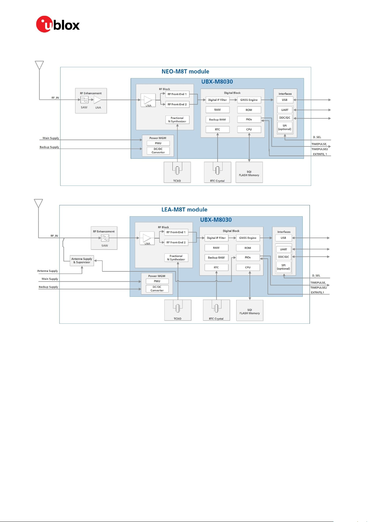
1.4 Block diagram
Figure 1: NEO-M8T block diagram
Figure 2: LEA-M8T block diagram
1.5 Supported GNSS constellations
The NEO-M8T and LEA-M8T GNSS modules are concurrent GNSS receivers that can receive and
track multiple GNSS systems: GPS, Galileo, GLONASS and BeiDou. Owing to the dual-frequency RF
front-end architecture, either GLONASS or BeiDou can be processed concurrently with GPS and
Galileo signals providing reception of three GNSS systems. By default M8T receivers are configured
for concurrent GPS and GLONASS, including QZSS reception. If power consumption is a key factor,
then the receiver should be configured for a single GNSS operation using GPS, Galileo, GLONASS or
BeiDou with QZSS and SBAS disabled. The modules can be configured to receive any single GNSS
constellation or within the set of permissible combinations shown below.
UBX-15025193 - R05 Functional description Page 8 of 36
Production Information
Page 9

NEO/LEA-M8T - Data sheet
GPS
Galileo
GLONASS
BeiDou
• • – – • • • – • • – • • – • – • – –
•
– • •
–
– • – • – – •
•
Table 2 Permissible GNSS combinations (• = enabled)
☞ The augmentation systems: SBAS and QZSS can be enabled only if GPS operation is configured.
☞ Galileo is not enabled in the default configuration.
1.5.1 GPS
The NEO-M8T and LEA-M8T GNSS modules are designed to receive and track the L1C/A signals
provided at 1575.42 MHz by the Global Positioning System (GPS). The modules can receive and
process GPS concurrently with Galileo and one of GLONASS or BeiDou.
1.5.2 GLONASS
The NEO-M8T and LEA-M8T GNSS modules can receive and process GLONASS concurrently with
GPS and Galileo together, or BeiDou. The Russian GLONASS satellite system is a fully deployed
alternative to the US-based Global Positioning System (GPS). The modules are designed to receive
and track the L1OF signals GLONASS provides around 1602 MHz. The ability to receive and track
GLONASS L1OF satellite signals allows design of GLONASS receivers where required by regulations.
1.5.3 BeiDou
The NEO-M8T and LEA-M8T GNSS modules can receive and process BeiDou concurrently with GPS
and Galileo together, or GLONASS. The modules are designed to receive and track the B1 signals
provided at 1561.098 MHz by the BeiDou navigation satellite system. The ability to receive and track
BeiDou B1 satellite signals in conjunction with GPS results in higher coverage, improved reliability and
better accuracy.
1.5.4 Galileo
The NEO-M8T and LEA-M8T GNSS modules can receive and track the E1-B/C signals centered on the
GPS L1 frequency band. GPS and Galileo signals can be processed concurrently together with either
BeiDou or GLONASS signals, enhancing coverage, reliability and accuracy. The SAR return link
message (RLM) parameters for both short and long versions are decoded by the receiver and made
available to users via UBX proprietary messages. See the u-blox 8 / u-blox M8 Receiver Description
including Protocol Specification [3] for more information.
☞ For further guidance on the use of specific GNSS constellations in timing applications, contact
your local u-blox support team.
1.6 Assisted GNSS (A-GNSS)
Supply of aiding information, such as ephemeris, almanac, approximate position and time, will reduce
the time-to-first-fix significantly and improve the acquisition sensitivity. The NEO-M8T and LEA-M8T
products support the u-blox AssistNow Online and AssistNow Offline A-GNSS services, support
AssistNow Autonomous, and are OMA SUPL-compliant.
UBX-15025193 - R05 Functional description Page 9 of 36
Production Information
Page 10

NEO/LEA-M8T - Data sheet
1.6.1 AssistNow
With AssistNow Online, an internet-connected GNSS device downloads assistance data from u-blox’s
AssistNow Online Service at system start-up. AssistNow Online is network-operator independent and
globally available. Devices can be configured to request only ephemeris data for those satellites
currently visible at their location, thus minimizing the amount of data transferred.
TM
Online
☞ The AssistNow Online service provides data for GPS, GLONASS, BeiDou, Galileo and QZSS.
1.6.2 AssistNow
With AssistNow Offline, users download u-blox’s long-term orbit data from the internet at their
convenience. The orbit data can be stored in the NEO-M8T and LEA-M8T GNSS receivers' SQI flash
memory. Thus the service requires no connectivity at system start-up, enabling a position fix within
seconds, even when no network is available. AssistNow Offline offers augmentation for up to 35 days.
TM
Offline
☞ AssistNow Offline service provides data for GPS and GLONASS only, BeiDou and Galileo are not
currently supported.
1.6.3 AssistNow
AssistNow Autonomous provides aiding information without the need for a host or external network
connection. Based on previous broadcast satellite ephemeris data downloaded to and stored by the
GNSS receiver, AssistNow Autonomous automatically generates accurate satellite orbital data
(“AssistNow Autonomous data”) that is usable for future GNSS position fixes. The concept capitalizes
on the periodic nature of GNSS satellites: their position in the sky is basically repeated every 24 hours.
By capturing strategic ephemeris data at specific times over several days, the receiver can predict
accurate satellite ephemeris for up to six days after initial reception.
TM
Autonomous
u-blox’s AssistNow Autonomous benefits are:
Faster fix in situations where GNSS satellite signals are weak
No connectivity required
Compatible with AssistNow Online and Offline (can work stand-alone, or in tandem with these
services)
No integration effort; calculations are done in the background, transparent to the user.
☞ For more details, see the u-blox 8 / u-blox M8 Receiver Description including Protocol Specification
[3] and the MGA Services User Guide [6].
1.7 Augmentation systems
1.7.1 Satellite-based augmentation system (SBAS)
The NEO-M8T and LEA-M8T timing receivers optionally support SBAS (including WAAS in the US,
EGNOS in Europe, MSAS in Japan and GAGAN in India) to deliver improved location accuracy within
the regions covered. However, the additional inter-standard time calibration step used during SBAS
reception results in degraded time accuracy overall.
☞ SBAS reception is disabled by default in NEO-M8T and LEA-M8T.
1.7.2 QZSS
The Quasi-Zenith Satellite System (QZSS) is a regional navigation satellite system that transmits
additional GPS L1 C/A signals for the Pacific region covering Japan and Australia. The NEO-M8T and
LEA-M8T modules are able to receive and track these signals concurrently with GPS signals, resulting
UBX-15025193 - R05 Functional description Page 10 of 36
Production Information
Page 11

NEO/LEA-M8T - Data sheet
Message type
Description
1
Differential GPS corrections
2
Delta differential GPS corrections
3
GPS reference station parameters
9
GPS partial correction set
in better availability especially under challenging signal conditions, for example, in urban canyons. The
L1- SAIF signal provided by QZSS can be enabled for reception via a GNSS configuration message.
1.7.3 IMES
The Japanese Indoor Messaging System (IMES) system is used for indoor position reporting using
low-power transmitters which broadcast a GPS–like signal. The NEO-M8T and LEA-M8T modules can
be configured to receive and demodulate the signal to provide an in-door location estimate.
☞ This service is authorized and available only in Japan.
☞ IMES reception is disabled by default
1.7.4 Differential GPS (D-GPS)
The use of differential GPS data improves GPS position accuracy using real-time data from a nearby
reference receiver or network. D-GPS starts on receipt of valid data according RTCM 10402.3:
“Recommended Standards for Differential GNSS”. RTCM cannot be used together with SBAS and is
applicable only to GPS signals in the NEO-M8T and LEA-M8T. The RTCM implementation supports
the following RTCM 2.3 messages:
Table 3: Supported RTCM 2.3 messages
☞ For more details, see the u-blox 8 / u-blox M8 Receiver Description including Protocol Specification
[3].
1.8 Precision timing, raw data and low duty-cycle operation
1.8.1 Time mode
The NEO-M8T and LEA-M8T support:
a special fixed-position mode improving timing stability in stationary applications
optional single-SV time tracking for difficult RF environments (available in fixed-position mode
only)
receiver autonomous integrity monitoring (RAIM) indication for timing
dual configurable 0.25 Hz to 10 MHz time-pulse outputs
Improved timing performance can be delivered by using the fixed-position mode in stationary
applications. In this mode, positioning uncertainties are eliminated from the calculation of time which
reduces the error and variation in the phase of the TIMEPULSE signal outputs. The known position
also reduces the minimum number of measurements and hence good satellite signals required to
enable RAIM, reported in message UBX-TIM-TP.
Operation with as few as one single satellite signal is supported in this mode, enabling continuity of
timing in situations with extremely limited sky view. The minimum number of signals required may be
increased using message UBX-CFG-NAVX5.
Fixed-position mode is configured with the message CFG-TMODE2 according to Table 4 below either
by initiating a survey-in process (which can take some time to complete accurately) or by entering the
position of the antenna if known. The survey-in process may be performed during discontinuous
UBX-15025193 - R05 Functional description Page 11 of 36
Production Information
Page 12

NEO/LEA-M8T - Data sheet
Time mode settings
Description
Disabled
Standard PVT operation
Survey-in
The receiver computes the average position over an extended time period until a predefined
standard deviation has been reached and the minimum observation time has passed by.
Afterwards the receiver will be automatically set to fixed mode and the timing features will be
activated. Progress during survey-in can be monitored using the TIM-SVIN message.
Fixed mode
Fixed mode is initiated automatically at the completion of a survey-in process or when the
receiver is configured with its 3D position (and standard deviation of uncertainty). Fixed
position coordinates can be entered in ECEF (Earth Center Earth fixed format) or as latitude,
longitude and height.
(on/off low duty-cycle) operation if necessary. In this case the receiver should be allowed to make
several fixes during each cycle to avoid excessive degradation of the survey-in accuracy.
Table 4: Time mode settings
A constellation-specific variant of Universal Ccoordinated Time (UTC) is used as the receiver's basis
for conversion from native GNSS time to UTC. The selection is explicitly specified in message
CFG-NAV5. This is significant when the time-pulse output has been configured (CFG-TP5) to be
aligned with UTC rather than a GNSS time. In this case, a version of UTC should be selected in
CFG-NAV5 of which the receiver has knowledge (from aiding messages or from the GNSS signals
themselves). Other selections may result in relatively large timing uncertainties until the offset
between GNSS time and the selected UTC becomes available (from satellite signals or aiding
messages).
☞ For more information, see the u-blox 8 /u-blox M8 Receiver Description including Protocol
Specification [3].
1.8.2 Timepulse and frequency outputs
The NEO-M8T and LEA-M8T modules provide two time pulse outputs that can be configured in rate
from 0.25 Hz up to 10 MHz by message CFG-TP5. Time pulse alignment can be configured to UTC or
GNSS time according to the standard used in signals being received or to an alternate standard where
inter-standard calibration data is available (from the signals themselves or by aiding). The time pulses
are generated on edges of an asynchronous clock; for pulse rates below 2 Hz, the exact phase of the
TIMEPULSE output is reported before each pulse in the TIM-TP message.
☞ Times reported in navigation messages such as NAV-PVT report the time of the preceding pulse.
1.8.3 Time mark
The NEO-M8T and LEA-M8T modules can be used for precise time measurements with submicrosecond resolution using the external interrupt pins (EXTINT0 and EXTINT1). Rising and falling
edges of these signals are time-stamped to GNSS or UTC time, counted and the results reported in
message TIM-TM2. The reference time is the same as set for TIMEPULSE with CFG-TP5.
☞ For more information, see the u-blox 8 / u-blox M8 Receiver Description including Protocol
Specification [3].
1.8.4 Timing integrity and availability
The NEO-M8T and LEA-M8T modules include the following measures to support applications
requiring excellent timing integrity:
Time uncertainty estimation:
The receiver estimates the uncertainty of the time-pulse and time report based on the observed
signal characteristics. The time and uncertainties are reported together for each standardsspecific time-base in NAV-TIME messages. Under poor signal conditions the estimate of
UBX-15025193 - R05 Functional description Page 12 of 36
Production Information
Page 13

NEO/LEA-M8T - Data sheet
uncertainty may include unresolved ambiguities; for example, for GPS these might be epoch
(millisecond), bit (20 ms) and sub-frame (6 s). Where the output time-base standard is derived
from a different constellation (for example, GPS-time from GLONASS), the estimate of
uncertainty includes inter-constellation offset uncertainties. The estimate of uncertainty is used
to disable or modify the time-pulse output by comparison with the “tAcc” parameter (after
conversion to distance) configured in message CFG-NAV5.
Multi-GNSS signal reception:
Particularly where sky views are limited, the timing accuracy is improved by combining
measurements from two constellations. Inter-GNSS timing offsets are derived locally by the
receiver whenever a timing fix can be achieved independently from each constellation (locally
derived offsets automatically account for antenna, filter and cable dispersion). These offsets are
then used for subsequent combined fixes. Where inter-GNSS offsets cannot be derived locally,
offsets broadcast by the constellation satellites are used where available.
Fix redundancy (RAIM):
The receiver automatically and continually adjusts the significance of individual signal
measurements in the reported estimate of time according to its quality and consistency. This
ensures that the integrity of the reported time is protected from individual faulty signals or
measurements so long as there are more signals in use than the minimum required. The minimum
number changes depending on the situation but whenever it is exceeded “RAIM active” is set in
message TIM-TP to indicate that this protection is active.
Aiding:
While a GNSS receiver may be able to achieve a vernier (sub-microsecond) time-fix even under poor
signal conditions, it may be slow or unable to resolve higher order ambiguities (especially whole
milliseconds for GPS). Sub-millisecond time aiding may be applied to u-blox NEO-M8T and LEAM8T modules by means of a pulse to one of the EXTINT pins in conjunction with a MGA-INI-TIME
message, enabling immediate resolution of ambiguities as well as accelerating time to fix.
1.8.5 Raw data
The NEO/LEA-M8T modules provide raw measurement data for civil L1 band GPS, GLONASS and
BeiDou signals including pseudo-range and carrier phase, Doppler and message payloads. The data
contained in the RXM-RAWX message follows the conventions of a multi-GNSS RINEX 3 observation
file and includes pseudo-range, carrier phase and Doppler measurements along with measurement
quality data. The RXM-SFRBX message provides the demodulated, parity-checked navigation and
signaling message bits for each satellite currently tracked by the receiver including GPS, GLONASS
and BeiDou constellations, SBAS satellites, the QZSS L1S signal and IMES beacons.
Raw measurement data are available once the receiver has established data bit synchronization and
time-of-week. Message data are available for all signals tracked at a sufficient level to achieve data
bit and frame synchronization. For more information, see the u-blox 8 / M8 Receiver Description
including Protocol Specification [3].
1.8.6 Low duty-cycle operation
The NEO-M8T and LEA-M8T low-power timing modules support energy-saving automatic on/off
interval low duty-cycle operation in conjunction with their precision timing features. On/off low dutycycle operation is enabled with the power save mode setting in message CFG-RXM and on/off mode
in message CFG-PM2. Through a set of period and time-out parameters defined in the CFG-PM2
message the receiver can be configured to deliver a new time fix at intervals with a limit on total energy
consumed for searches if no fix can be achieved. Note that the time-pulse output is not available while
the receiver is in the “off” section of each cycle.
The duty-cycle of operation may be reduced significantly by:
provision of sub-millisecond time-aiding to accelerate ambiguity resolution (see 1.8.4 above),
UBX-15025193 - R05 Functional description Page 13 of 36
Production Information
Page 14

NEO/LEA-M8T - Data sheet
provision of ephemeris aiding (message MGA-GPS-EPH) to avoid the need to receive new data
transmissions from the satellites themselves.
Survey-in is supported in conjunction with low duty-cycle operation providing the accuracy benefits of
a long observation interval without the need to keep the receiver continuously powered. To achieve
the best sensitivity on first deployment at a new site, the receiver should be allowed to operate
continuously until the first fix is achieved (up to 20 minutes in very poor signal conditions) before
engaging low duty cycle operation.
☞ For more information, see the u-blox 8 / u-blox M8 Receiver Description including Protocol
Specification [3].
1.9 TIMEPULSE
Two configurable time pulse signals (TIMEPULSE, TIMPULSE2) are available with u-blox NEO-M8T
and LEA-M8T timing modules. The TIMEPULSE outputs generate pulse trains synchronized with
GNSS or UTC time grid with intervals configurable over a wide frequency range. Thus it may be used
as a low frequency time synchronization pulse or as a high frequency reference signal.
☞ The TIMEPULSE2 (TP2) pin should not be held LO during start-up.
By default the primary time pulse signal is enabled and configured to 1 pulse per second. For more
information, see the u-blox 8 / u-blox M8 Receiver Description including Protocol Specification [3].
1.10 Odometer
The odometer provides information on the travelled ground distance (in meters) using solely the
position and Doppler-based velocity of the navigation solution. For each computed travelled distance
since the last odometer reset, the odometer estimates a 1-sigma accuracy value. The total
cumulative ground distance is maintained and saved in the BBR memory.
☞ The odometer feature is disabled by default. For more details, see the u-blox 8 / u-blox M8 Receiver
Description including Protocol Specification [3].
1.11 Data logging
The u-blox NEO-M8T and LEA-M8T receivers can be used in data logging applications. The data
logging feature enables continuous storage of position, velocity and time information to an onboard
SQI flash memory. It can also log the distance from the odometer. The information can be downloaded
from the receiver later for further analysis or for conversion to a mapping tool. For more information,
see the u-blox 8 / u-blox M8 Receiver Description including Protocol Specification [3].
1.12 Geofencing
The u-blox NEO-M8T and LEA-M8T modules support up to four circular geofencing areas defined on
the Earth’s surface using a 2D model. Geofencing is active when at least one geofence is defined, the
current status can be found by polling the receiver. A GPIO pin can be nominated to indicate status or
wake up a host on activation.
1.13 Message integrity protection
The NEO-M8T and LEA-M8T provide a function to detect third party interference with the UBX
message stream sent from receiver to host. The security mechanism “signs” nominated messages
via a subsequent UBX message. This message signature is then compared with one generated by the
host to determine if the message data has been altered.
UBX-15025193 - R05 Functional description Page 14 of 36
Production Information
Page 15

NEO/LEA-M8T - Data sheet
Protocol
Type
NMEA 0183, version 4.0 (V2.3 or V4.1 configurable)
Input/output, ASCII, 0183, version 4.0
UBX
Input/output, binary, u-blox proprietary
RTCM
Input message, 1, 2, 3, 9
1.14 Spoofing detection
Spoofing is a process whereby a malicious third party tries to control the reported position via a “fake”
GNSS broadcast signal. This may result in the form of reporting incorrect position, velocity or time.
To combat against this, the NEO-M8T and LEA-M8T modules include spoofing detection measures
to alert the host when signals appear to be suspicious. The receiver combines a number of checks on
the received signals looking for inconsistencies across several parameters.
1.15 EXTINT: External interrupt
The NEO-M8T and LEA-M8T receivers feature two EXTINT pins, each of which can be used to switch
the receiver on and off or for aiding.
For more information about how to implement and configure these features, see the u-blox 8 / u-blox
M8 Receiver Description including Protocol Specification [3] and the relevant Hardware integration
manual [1] or [2].
1.15.1 Power control
The power control feature allows overriding the automatic active / inactive cycle of power save mode.
The state of the receiver can be controlled through an EXTINT pin.
The receiver can also be forced OFF using EXTINT when power save mode is not active.
1.15.2 Aiding
An EXTINT pin can be used to supply time or frequency aiding data to the receiver.
For time aiding, hardware time synchronization can be achieved by connecting an accurate time pulse
to the EXTINT pin.
Frequency aiding can be implemented by connecting a periodic rectangular signal with a frequency up
to 500 kHz and arbitrary duty cycle (low/high phase duration must not be shorter than 50 ns) to an
EXTINT pin. The applied frequency value is provided to the receiver using UBX messages.
☞ For more information, see the u-blox 8 / u-blox M8 Receiver Description including Protocol
Specification [3].
1.16 Protocols and interfaces
Table 5: Available protocols
All protocols are available on UART, USB, DDC (I2C-compliant) and SPI. For specification of the various
protocols, see the u-blox 8 / u-blox M8 Receiver Description including Protocol Specification [3].
1.17 Interfaces
A number of interfaces are provided for data communication. The embedded firmware uses these
interfaces according to their respective protocol specifications.
UBX-15025193 - R05 Functional description Page 15 of 36
Production Information
Page 16

NEO/LEA-M8T - Data sheet
1.17.1 UART
The NEO-M8T and LEA-M8T modules include one UART interface, which can be used for
communication to a host. It supports configurable baud rates. For supported baud rates, see the
u-blox 8 / u-blox M8 Receiver Description including Protocol Specification [3].
☞ Designs must allow access to the UART and the SAFEBOOT_N function pin for future service,
updates and reconfiguration.
1.17.2 USB
USB interface compatible with USB version 2.0 FS (Full Speed, 12 Mbit/s), can be used for
communication as an alternative to the UART. The pull-up resistor on pin USB_DP is integrated to
signal a full-speed device to the host. The VDD_USB pin supplies the USB interface. The u-blox USB
(CDC-ACM) driver supports Windows Vista plus Windows 7 and 8 operating systems. A separate
driver (CDC-ACM) is not required for Windows 10 which has a built-in USB-serial driver. However,
plugging initially into an internet-connected Windows 10 PC downloads the u-blox combined sensor
and VCP driver package.
USB drivers can be down-loaded from the u-blox web site, www.u-blox.com.
1.17.3 SPI
The SPI interface is designed to allow communication to a host CPU. The interface can be operated in
slave mode only. The maximum transfer rate using SPI is 125 kB/s and the maximum SPI clock
frequency is 5.5 MHz (see Figure 5). Note that SPI is not available in the default configuration because
its pins are shared with the UART and DDC interfaces. The SPI interface can be enabled by connecting
D_SEL (pin 2) to ground (see section 3.1)
1.17.4 Display data channel (DDC)
An I2C-compliant DDC interface is available for communication with an external host CPU or u-blox
cellular modules. The interface can be operated in slave mode only. The DDC protocol and electrical
interface are fully compatible with Fast-Mode of the I2C industry standard. Since the maximum SCL
clock frequency is 400 kHz, the maximum transfer rate is 400 kbit/s.
1.18 Clock generation
1.18.1 Oscillators
The NEO-M8T and LEA-M8T GNSS timing modules incorporate a TCXO for accelerated weak signal
acquisition and stable timing output. The TCXO is carefully selected and screened for stability and
against frequency perturbations across the full operating range (–40 °C to +85 °C).
1.18.2 Real-time clock (RTC) and hardware backup mode
The RTC can be maintained by a secondary 32 kHz oscillator using an RTC crystal. If the main supply
voltage is removed, a battery connected to V_BCKP allows the RTC to continue to run with very low
power consumption. The same supply also maintains a static backup memory for current
configuration information, recent ephemeris, location and auxiliary data necessary to ensure the
fastest re-acquisition when the primary power supply is restored.
1.19 Power management
u-blox GNSS timing product technology offers a power-optimized architecture with built-in
autonomous power saving functions to minimize power consumption at any given time. Furthermore,
UBX-15025193 - R05 Functional description Page 16 of 36
Production Information
Page 17

NEO/LEA-M8T - Data sheet
the receivers can be used in three operating modes: continuous mode for best performance or one of
two power save modes for optimized power consumption. A high-efficiency DC/DC converter is
integrated to minimize power consumption and dissipation across the range of supported power
supply voltages.
☞ For the best GNSS performance, use the power management setup message UBX-CFG-PMS to
configure the full power mode.
1.19.1 Operating modes
The NEO-M8T and LEA-M8T modules have two operating modes:
Continuous mode for best GNSS performance
On/off duty-cycle mode to reduce energy-use in discontinuous operation
☞ Timing and raw data features are not fully supported in cyclic power save mode. There is limited
support for GLONASS, BeiDou and Galileo signals in on/off duty-cycle mode, notably in efficient
reception and use of ephemeris data.
1.19.2 Continuous mode
Continuous mode uses the acquisition engine at full performance, resulting in the shortest possible
TTFF and the highest sensitivity. It searches for all possible satellites until the Almanac is completely
downloaded. The receiver then switches to the tracking engine to lower power consumption.
Thus, a lower tracking current consumption level will be achieved when:
A valid GNSS position is obtained
The entire Almanac has been downloaded
The Ephemeris for each satellite in view is valid
1.19.3 On/off interval power save mode
Where an application requires only intermittent navigation or timing information, an on/off low dutycycle power save mode can be employed. In this mode the receiver starts at intervals configurable
between a few seconds and several hours. Alternatively, the receiver can be re-started on demand by
a hardware signal applied to either EXTINT input or activity on the UART. An EXTINT pin can also be
configured (by CFG-PM2) to define durations when the receiver should be held on or off by hardware
control.
With each start, the receiver stays on for long enough to deliver a new fix or download new ephemeris
if necessary to make a fix. The receiver makes use of one or more of the following sources of aiding to
reduce the duration of each fix and thereby minimize overall energy use:
built-in RTC (time-aiding) or fine time-aiding delivered to an EXTINT pin (see MGA-INI-TIME
messages)
last known or fixed position (see MGA-INI and CFG-TMODE2 messages)
ephemeris and auxiliary aiding data messages (see MGA-GPS, MGA-GLO and MGA-BDS
messages)
☞ On/off duty-cycle power save mode may not provide the minimum energy use when GLONASS,
BeiDou or Galileo signal reception is enabled without ephemeris aiding.
☞ For more information about power management strategies, see the u-blox 8 / u-blox M8 Receiver
Description including Protocol Specification [3].
UBX-15025193 - R05 Functional description Page 17 of 36
Production Information
Page 18

NEO/LEA-M8T - Data sheet
Parameter
Specification
Antenna type
Passive and active antenna
Active antenna recommendations
Minimum gain
Maximum gain
Maximum noise figure
5 dB (at module input)
40 dB 12 (at module input)
1.5 dB
10
11
12
1.20 Antenna
1.20.1 Antenna type
The NEO-M8T includes a SAW filter and an additional LNA and is suitable for use with both passive10
and active11 antennas. The LEA-M8T includes a SAW filter and is suitable for use with active antennas
and antenna distribution systems. Within the recommended range below, lower overall gain can
improve immunity to interference in most situations; higher gain offers slightly better sensitivity.
Table 6: Antenna specifications
1.20.2 Antenna supervision
The LEA-M8T includes a built-in antenna bias supply for nominal 3 V antennas enabled by linking the
filtered VCC_RF supply output pin to the V_ANT antenna supply input pin with a series resistor. The
module then controls the power supply to the antenna, applying power whenever the receiver is active
and removing power during power-save idle times and if a short-circuit is detected. Short-circuit is
detected if the voltage at the antenna supply falls close to zero and is indicated as an alarm in
message MON-HW.
Optionally the EXTINT1 pin may be reassigned to antenna supervision, allowing an external circuit to
indicate to the module that the antenna is open-circuit. This condition is then reported in message
MON-HW.
The NEO-M8T provides a control output for an external antenna supply switch. Antenna supervision
is configurable in both modules using message CFG-ANT.
Antenna supervision is configurable in both modules using message CFG-ANT.
☞ For more details on antenna supervision in NEO-M8T or LEA-M8T, see the relevant hardware
integration manual [1] or [2].
For integration of M8T modules with Cellular products, see the NEO-8Q / NEO-M8 Hardware integration manual [1].
For using active antennas with NEO-M8T modules, see the NEO-8Q / NEO-M8 Hardware integration manual [1].
Gain above 20 dB should be avoided unless interference in the band 1463 MHz to 1710 MHz is adequately controlled.
UBX-15025193 - R05 Functional description Page 18 of 36
Production Information
Page 19

NEO/LEA-M8T - Data sheet
No
Name
I/O
Description
1
TP2/SAFEBOOT_N
I/O
Timepulse 2 / SAFEBOOT_N (for future service, updates and reconfiguration,
must not be held LO during start-up)
2
D_SEL
I
Interface select
3
TIMEPULSE
O
Time pulse (1PPS)
4
EXTINT0
I
External interrupt pin 0
5
USB_DM
I/O
USB data
6
USB_DP
I/O
USB data
7
VDD_USB
I
USB supply
8
RESET_N
I
RESET_N
9
VCC_RF
O
Output voltage RF section
10
GND I Ground
11
RF_IN
I
GNSS signal input
12
GND I Ground
13
GND I Ground
14
LNA_EN13
O
Enable external LNA / Antenna control
15
EXTINT1
I
External interrupt pin 1
16
Reserved
-
Reserved
17
Reserved
-
Reserved
18
SDA
SPI CS_N
I/O
DDC data if D_SEL =1 (or open)
SPI chip select if D_SEL = 0
19
SCL
SPI CLK
I/O
DDC clock if D_SEL =1 (or open)
SPI clock if D_SEL = 0
20
TXD
SPI MISO
O
Serial port if D_SEL =1 (or open)
SPI MISO if D_SEL = 0
21
RXD
SPI MOSI
I
Serial port if D_SEL =1 (or open)
SPI MOSI if D_SEL = 0
22
V_BCKP
I
Backup voltage supply
23
VCC I Supply voltage
24
GND I Ground
13
2 Pin definition
2.1 NEO-M8T pin assignment
Figure 3: NEO-M8T pin assignment
Table 7: NEO-M8T pinout
Compatible with pin labelled ANT_ON in predecessor products
UBX-15025193 - R05 Pin definition Page 19 of 36
Production Information
Page 20
NEO/LEA-M8T - Data sheet
No
Name
I/O
Description
1
SDA
SPI CS_N
I/O
DDC data if D_SEL =1 (or open)
SPI chip select if D_SEL = 0
2
SCL
SPI CLK
I/O
DDC clock if D_SEL =1 (or open)
SPI clock if D_SEL = 0
3
TXD
SPI MISO
O
Serial port if D_SEL =1 (or open)
SPI MISO if D_SEL = 0
4
RXD
SPI MOSI
I
Serial port if D_SEL =1 (or open)
SPI MOSI if D_SEL = 0
5
D_SEL
I
Interface select
6
VCC I Supply voltage
7
GND - Ground
8
VCC_OUT
O
Output voltage (VCC)
9
Reserved
-
Reserved
10
RESET_N
I
RESET_N
11
V_BCKP
I
Backup voltage supply
12
TP2/SAFEBOOT_N
I/O
Timepulse 2 / SAFEBOOT_N (must not be held LO during start-up)
13
GND - Ground
14
GND - Ground
15
GND - Ground
16
RF_IN
I
GPS signal input
17
GND - Ground
18
VCC_RF
O
Output voltage RF section
19
V_ANT
I
Active antenna voltage supply
20
EXTINT114
I
External interrupt pin 1, can be configured as active antenna open circuit
detection pin: ANT_DET_N
21
Reserved
-
Reserved
22
Reserved
-
Reserved
23
Reserved
-
Reserved
14
☞ Pins designated Reserved should not be used. For more information about pinouts, see the NEO-
8Q / NEO-M8 Hardware integration manual [1].
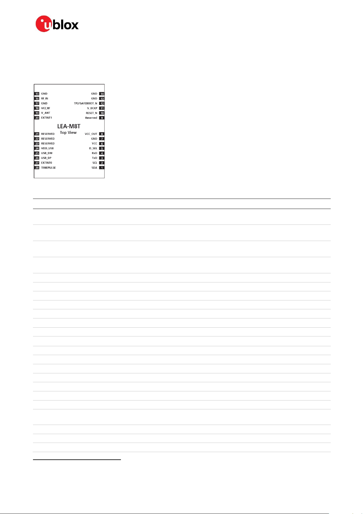
2.2 LEA-M8T pin assignment
Figure 4: LEA-M8T pin assignment
Compatible with pin labelled AADET_N/EXTINT1 in predecessor products
UBX-15025193 - R05 Pin definition Page 20 of 36
Production Information
Page 21

NEO/LEA-M8T - Data sheet
No
Name
I/O
Description
24
VDD_USB
I
USB supply
25
USB_DM
I/O
USB data
26
USB_DP
I/O
USB data
27
EXTINT0
I
External interrupt pin 0
28
TIMEPULSE
O
Timepulse (1 PPS)
Table 8: LEA-M8T pinout
☞ Pins designated Reserved should not be used. For more information about pinouts, see the LEA-
M8S / M8T Hardware integration manual [2].
UBX-15025193 - R05 Pin definition Page 21 of 36
Production Information
Page 22

NEO/LEA-M8T - Data sheet
PIN NUMBER
NEO-M8T
PIN NUMBER
LEA-M8T
D_SEL=”1”
(left open)
D_SEL =”0”
(connected to GND)
20 3 UART TX
SPI MISO
21 4 UART RX
SPI MOSI
19 2 DDC SCL
SPI CLK
18 1 DDC SDA
SPI CS_N
3 Configuration management
Configuration settings can be modified with UBX configuration messages. The modified settings
remain effective until power-down or reset. Settings can also be saved in battery-backed RAM, flash
or both using the UBX-CFG-CFG message. If settings have been stored in battery-backed RAM then
the modified configuration will be retained as long as the backup battery supply is not interrupted.
Settings stored in flash memory will remain effective even after power-down and do not require
backup battery supply.
3.1 Interface selection (D_SEL)
At startup, the D_SEL pin determines which data interfaces are used for communication. If D_SEL is
set high or left open, UART and DDC become available. If D_SEL is set low, that is, connected to
ground, the modules can communicate to a host via SPI.
Table 9: Data interface selection by D_SEL
UBX-15025193 - R05 Configuration management Page 22 of 36
Production Information
Page 23

NEO/LEA-M8T - Data sheet
Parameter
Symbol
Module
Condition
Min
Max
Units
Power supply voltage
VCC
All –0.5
3.6 V Backup battery voltage
V_BCKP
All –0.5
3.6 V USB supply voltage
VDD_USB
All –0.5
3.6
V
Input pin applied DC voltage
Vin
All –0.5
3.6 V Vin_usb
All –0.5
VDD_USB
V
Vrfin
NEO-M8T
LEA-M8T15
0 - 6 - V
DC current through any digital I/O pin
(except supplies)
Ipin 10
mA
VCC_RF output current
ICC_RF
All
100
mA
Input power at RF_IN
Prfin
All
source impedance
= 50 , continuous
wave
13
dBm
Antenna bias voltage
V_ANT
6 V
Antenna bias current
I_ANT
100
mA
Storage temperature
Tstg
All –40
85
°C
15
4 Electrical specification
☞ The limiting values given are in accordance with the Absolute Maximum Rating System (IEC 134).
Stress above one or more of the limiting values may cause permanent damage to the device. These
are stress ratings only and operation of the device at these or at any other conditions above those
given in the characteristics sections of the specification is not implied. Exposure to these limits
for extended periods may affect device reliability.
☞ Where application information is given, it is advisory only and does not form part of the
specification. For more information, see the NEO-8Q / NEO-M8 Hardware integration manual [1]
and the LEA-M8S / M8T Hardware integration manual [2].
4.1 Absolute maximum rating
Table 10: Absolute maximum ratings
⚠ Stressing the device beyond the “Absolute Maximum Ratings” may cause permanent damage.
These are stress ratings only. The product is not protected against overvoltage or reversed
voltages. If necessary, voltage spikes exceeding the power supply voltage specification, given in
Table 10, must be limited to values within the specified boundaries by using appropriate
protection diodes.
Antenna bias is supplied by LEA-M8T module
UBX-15025193 - R05 Electrical specification Page 23 of 36
Production Information
Page 24

NEO/LEA-M8T - Data sheet
Parameter
Symbol
Modules
Min
Typical
Max
Units
Condition
Power supply voltage
VCC
All
2.7
3.0
3.6 V
Supply voltage USB
VDDUSB
All
3.0
3.3
3.6 V
Backup battery voltage
V_BCKP
All
1.4 3.6 V
Backup battery current
I_BCKP
NEO-M8T
15 µA
V_BCKP = 1.8
V, VCC = 0 V
LEA-M8T
17
SW backup current
I_SWBCKP
NEO-M8T
30 µA
VCC = 3 V
LEA-M8T
50
Input pin voltage range
Vin
All 0
VCC+0.5
V
Digital IO pin low level input voltage
Vil
All 0
0.2*VCC
V
Digital IO pin high level input voltage
Vih
All
0.7*VCC
VCC
V Digital IO pin low level output voltage
Vol
All
0.4 V Iol = 4 mA
Digital IO pin high level output voltage
Voh
All
VCC–0.4
V
Ioh = 4 mA
Pull-up resistor for RESET_N (internal)
Rpu
All 11 kΩ
USB_DM, USB_DP
VinU
All
Compatible with USB with 27 Ω series resistance
V_ANT antenna bias voltage
V_ANT
LEA-M8T
2.7 5.5 V I
ANT
< –50 mA
Antenna bias voltage drop
V_ANT_DROP
LEA-M8T
0.1 V
ICC_RF =50
mA
VCC_RF voltage
VCC_RF
All VCC–0.1
V
VCC_RF output current
ICC_RF
All
50
mA
Receiver chain noise figure 16
NFtot
NEO-M8T
2.0 dB
LEA-M8T
4.7 Operating temperature
Topr
All
–40 85
°C
Parameter
Symbol
Module
Typ.
GPS
Typ.
GPS / GLONASS / QZSS / SBAS
Max
Units
Condition
Max. supply current 17
Iccp
All
67
mA
Average supply current 18
Icc
NEO-M8T
25
32 mA
Estimated at 3 V
LEA-M8T
21
28 mA
16
17
18
4.2 Operating conditions
☞ All specifications are at an ambient temperature of +25 °C. Extreme operating temperatures can
significantly impact specification values. Applications operating near the temperature limits
should be tested to ensure the specification.
Table 11: Operating conditions
☞ Operation beyond the specified operating conditions can affect device reliability.
4.3 Indicative current requirements
Table 12 lists examples of the total system supply current for a possible application.
☞ Values in Table 12 are provided for customer information only as an example of typical power
requirements. Values are characterized on samples, actual power requirements can vary
depending on FW version used, external circuitry, number of SVs tracked, signal strength, type of
start as well as time, duration and conditions of test.
Table 12: Indicative power requirements at VCC = 3.0 V
Only valid for the GPS band
Use this figure to dimension maximum current capability of power supply. Measure this parameter with 1 Hz bandwidth.
Simulated GNSS constellation using power levels of -130 dBm. VCC = 3.0 V Use to determine required battery capacity.
UBX-15025193 - R05 Electrical specification Page 24 of 36
Production Information
Page 25
NEO/LEA-M8T - Data sheet
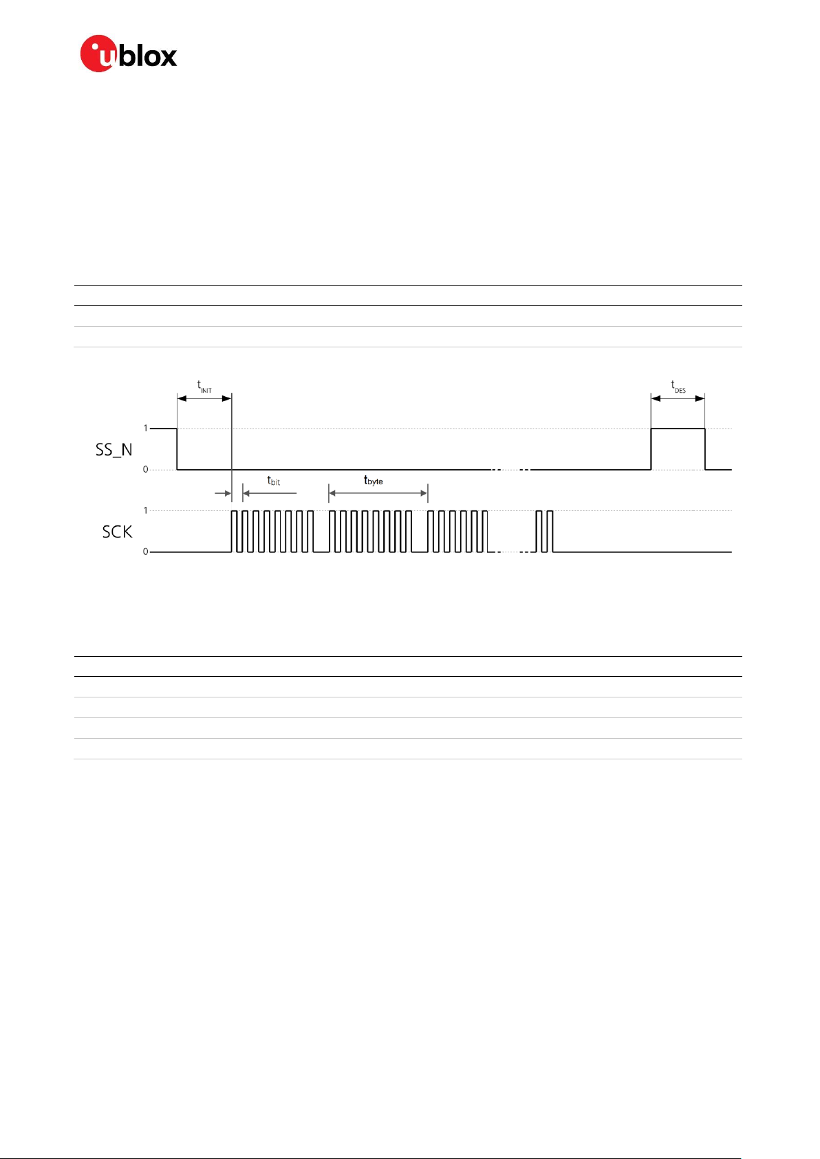
Symbol
Description
SPI CS_N (SS_N)
Slave select signal
SPI CLK (SCK)
Slave clock signal
Parameter
Description
Recommendation
t
INIT
Initialization time
>10 s
t
DES
Deselect time
1 ms.
t
bit
Minimum bit time
180 ns (5.5 MHz max bit frequency)
t
byte
Minimum byte period
8 s (125 kHz max byte frequency)
☞ For more information about power requirements, see the relevant M8T Hardware integration
manual [1] or [2].
☞ For more information on how to noticeably reduce current consumption, see the Power
Management Application Note [5].
4.4 SPI timing diagrams
In order to avoid incorrect operation of the SPI, the user needs to comply with certain timing
conditions. The following signals need to be considered for timing constraints:
Table 13: Symbol description
Figure 5: SPI timing diagram
4.4.1 Timing recommendations
The recommendations below are based on a firmware running from flash memory.
Table 14: SPI timing recommendations
☞ The values in Table 14 result from the requirement of an error-free transmission.
By allowing just a few errors and disabling the glitch filter, the bit rate can be increased
considerably.
4.5 DDC timing diagrams
The DDC interface is I2C Fast Mode compliant. For timing parameters consult the I2C standard.
☞ The maximum bit rate is 400 kbit/s. The interface stretches the clock when slowed down when
serving interrupts, so real bit rates may be slightly lower.
UBX-15025193 - R05 Electrical specification Page 25 of 36
Production Information
Page 26

NEO/LEA-M8T - Data sheet
5 Mechanical specifications
5.1 NEO-M8T
Figure 6: NEO dimensions
☞ For information about the paste mask and footprint, see the NEO-8Q / NEO-M8 Hardware
integration manual [1].
UBX-15025193 - R05 Mechanical specifications Page 26 of 36
Production Information
Page 27

NEO/LEA-M8T - Data sheet
5.2 LEA-M8T
Figure 7: LEA dimensions
☞ For information about the paste mask and footprint, see the LEA-M8S / M8T Hardware
integration manual [2].
UBX-15025193 - R05 Mechanical specifications Page 27 of 36
Production Information
Page 28
NEO/LEA-M8T - Data sheet
Products marked with this lead-free symbol on the product label comply with the
"Directive 2002/95/EC of the European Parliament and the Council on the
Restriction of Use of certain Hazardous Substances in Electrical and Electronic
Equipment" ”RoHS).
All u-blox M8 GNSS modules are RoHS compliant.
6 Reliability tests and approvals
6.1 Reliability tests
☞ The NEO-M8T and LEA-M8T modules are based on AEC-Q100 qualified GNSS chips.
Tests for product family qualifications are according to ISO 16750 "Road vehicles – environmental
conditions and testing for electrical and electronic equipment”, and appropriate standards.
6.2 Approvals
UBX-15025193 - R05 Reliability tests and approvals Page 28 of 36
Production Information
Page 29

NEO/LEA-M8T - Data sheet
7 Product handling and soldering
7.1 Packaging
To enable efficient production, production lot set-up and tear-down, NEO-M8T and LEA-M8T GNSS
modules are delivered as hermetically sealed, reeled tapes. For more information, see the u-blox
Package Information Guide [4].
7.1.1 Reels
NEO-M8T and LEA-M8T GNSS modules are both deliverable in quantities of 250 pcs on a reel.
NEO-M8T and LEA-M8T receivers are shipped on reel type B, as specified in the u-blox Package
Information Guide [4].
7.1.2 NEO-M8T tapes
The dimensions and orientations of the tapes for NEO-M8T modules are specified in Figure 8.
Figure 8: Dimensions and orientation for NEO-M8T modules on tape
UBX-15025193 - R05 Product handling and soldering Page 29 of 36
Production Information
Page 30

NEO/LEA-M8T - Data sheet
7.1.3 LEA-M8T tapes
The dimensions and orientations of the tapes for LEA-M8T modules are specified in Figure 9.
Pin 1 Sprocket Hole
Feed direction
Figure 9: Dimensions and orientation for LEA-M8T modules on tape
7.2 Shipment, storage and handling
For important information regarding shipment, storage and handling, see the u-blox Package
Information Guide [4].
7.2.1 Moisture sensitivity levels
The moisture sensitivity level (MSL) relates to the packaging and handling precautions required. NEOM8T and LEA-M8T modules are rated at MSL level 4.
☞ For MSL standard see IPC/JEDEC J-STD-020, which can be downloaded from www.jedec.org.
☞ For more information regarding MSL, see the u-blox Package Information Guide [4].
7.2.2 Reflow soldering
Reflow profiles are to be selected according u-blox recommendations (see the relevant Hardware
integration manual [1] or [2]).
UBX-15025193 - R05 Product handling and soldering Page 30 of 36
Production Information
Page 31

NEO/LEA-M8T - Data sheet
Unless there is a galvanic coupling between the local GND
(i.e. the work table) and the PCB GND, the first point of
contact when handling the PCB must always be between
the local GND and PCB GND.
Before mounting an antenna patch, connect the ground of
the device.
When handling the RF pin, do not come into contact with
any charged capacitors and be careful when contacting
materials that can develop charges (e.g. patch antenna
~10 pF, coax cable ~50-80 pF/m, soldering iron).
To prevent electrostatic discharge through the RF input, do
not touch any exposed antenna area. If there is any risk
that such exposed antenna area is touched in a non-ESD
protected work area, implement proper ESD protection
measures in the design.
When soldering RF connectors and patch antennas to the
receiver’s RF pin, make sure to use an ESD safe soldering
iron (tip).
7.2.3 ESD handling precautions
⚠ NEO-M8T and LEA-M8T modules are electrostatic sensitive devices (ESD). Observe precautions
for handling! Failure to observe these precautions can result in severe damage to the GNSS
receiver!
GNSS receivers are electrostatic sensitive devices (ESD) and require special precautions when
handling. Particular care must be exercised when handling patch antennas, due to the risk of
electrostatic charges. In addition to standard ESD safety practices, the following measures should be
taken into account whenever handling the receiver:
UBX-15025193 - R05 Product handling and soldering Page 31 of 36
Production Information
Page 32

NEO/LEA-M8T - Data sheet
Interface
Settings
UART output
9600 baud, 8 bits, no parity bit, 1 stop bit
Configured to transmit both NMEA and UBX protocols, but only the following NMEA (and no
UBX) messages have been activated at start-up:
GGA, GLL, GSA, GSV, RMC, VTG, TXT, ZDA
USB output
Configured to transmit both NMEA and UBX protocols, but only the following NMEA (and no
UBX) messages have been activated at start-up:
GGA, GLL, GSA, GSV, RMC, VTG, TXT, ZDA
USB power mode: Bus-powered
UART input
9600 baud, 8 bits, no parity bit, 1 stop bit, autobauding disabled
Automatically accepts following protocols without need of explicit configuration:
UBX, NMEA, RTCM
The GNSS receiver supports interleaved UBX and NMEA messages.
USB input
Automatically accepts following protocols without need of explicit configuration:
UBX, NMEA
The GPS receiver supports interleaved UBX and NMEA messages.
USB power mode: Bus-powered
DDC
Fully compatible with the I2C industry standard, available for communication with an external
host CPU or u-blox cellular modules, operated in slave mode only. Default messages activated.
NMEA and UBX are enabled as input messages, only NMEA as output messages.
Maximum bit rate 400 kbit/s.
SPI
Allow communication to a host CPU, operated in slave mode only. Default messages activated.
SPI is not available in the default configuration.
TIMEPULSE
(1 Hz Nav)
1 pulse per second, synchronized at rising edge, pulse length 100 ms
8 Default messages
Table 15: Default messages
☞ Refer to the u-blox 8 / u-blox M8 Receiver Description including Protocol Specification [3] for
information about other settings.
UBX-15025193 - R05 Default messages Page 32 of 36
Production Information
Page 33

NEO/LEA-M8T - Data sheet
9 Labeling and ordering information
9.1 NEO-M8T product labeling
The labeling of u-blox M8 GNSS modules includes important product information. The location of the
NEO-M8T product type number is shown in Figure 10.
Figure 10: Location of product type number on u-blox NEO-M8T module label
9.2 LEA-M8T product labeling
The labeling of u-blox M8 GNSS modules includes important product information. The location of the
LEA-M8T product type number is shown in Figure 11.
Figure 11: Location of product type number on u-blox LEA-M8T module label
UBX-15025193 - R05 Labeling and ordering information Page 33 of 36
Production Information
Page 34
NEO/LEA-M8T - Data sheet
Format
Structure
Product Name
PPP-TGV
Ordering Code
PPP-TGV-T
Type Number
PPP-TGV-T-XX
Code
Meaning
Example
PPP
Product family
NEO
TG
Platform
M8 = u-blox M8
V
Variant
Function set (A-Z), T = Timing, R = DR, etc.
T
Option / Quality grade
Describes standardized functional element or quality grade
0 = Default variant, A = Automotive
XX
Product detail
Describes product details or options such as hard- and software revision, cable length,
etc.
Ordering code
Product
LEA-M8T-0
u-blox M8 GNSS Module, Timing, TCXO, flash, SAW, 17x22.4 mm, 250 pieces/reel
NEO-M8T-0
u-blox M8 GNSS Module, Timing, TCXO, flash, SAW, LNA, 12.2x16 mm, 250 pieces/reel
9.3 Explanation of codes
Three different product code formats are used. The Product Name is used in documentation such as
this data sheet and identifies all u-blox M8 products, independent of packaging and quality grade. The
Ordering Code includes options and quality, while the Type Number includes the hardware and
firmware versions. Table 16 shows the structure of these three different formats.
Table 16: Product code formats
The parts of the product code are explained in Table 17.
Table 17: Part identification code
9.4 Ordering codes
Table 18: Product ordering codes
☞ Product changes affecting form, fit or function are documented by u-blox. For a list of Product
Change Notifications (PCNs), see our website.
UBX-15025193 - R05 Labeling and ordering information Page 34 of 36
Production Information
Page 35

NEO/LEA-M8T - Data sheet
Revision
Date
Name
Comments
R01
28-Oct-2015
amil
Objective Specification
R02
03-May-2016
amil
Advance Information
R03
21-Jun-2016
amil
Production Information, minor update in Table 1and Table 8, removed
reference to message UBX-CFG-TM2
R04
05-May-2020
ghun, smos,
dama
Corrected NEO-M8T Vrfin maximum input voltage to 6V in Table 10.
Corrected invalid references.
Rebranding.
Editorial changes to reflect the latest company style guide changes.
Updated document information section for LEA-M8T-1-00 product.
R05
2-Jun-2020
mala
Updated type number and PCN reference for NEO-M8T on page 2.
Related documents
[1] NEO-8Q / NEO-M8 Hardware integration manual, UBX-15029985
[2] LEA-M8S / LEA-M8T Hardware integration manual, UBX-15030060
[3] u-blox 8 / u-blox M8 Receiver Description including Protocol Specification, UBX 13003221
[4] u-blox Package Information Guide, UBX-14001652
[5] Power Management Application Note, UBX-13005162
[6] MGA Services User Guide, UBX-13004360
☞ For regular updates to u-blox documentation and to receive product change notifications, register
on our homepage (www.u-blox.com).
Revision history
UBX-15025193 - R05 Related documents Page 35 of 36
Production Information
Page 36

NEO/LEA-M8T - Data sheet
u-blox Offices
North, Central and South America
u-blox America, Inc.
Phone: +1 703 483 3180
E-mail: info_us@u-blox.com
Regional Office West Coast:
Phone: +1 408 573 3640
E-mail: info_us@u-blox.com
Technical Support:
Phone: +1 703 483 3185
E-mail: support@u-blox.com
Headquarters
Europe, Middle East, Africa
u-blox AG
Phone: +41 44 722 74 44
E-mail: info@u-blox.com
Support: support@u-blox.com
Asia, Australia, Pacific
u-blox Singapore Pte. Ltd.
Phone: +65 6734 3811
E-mail: info_ap@u-blox.com
Support: support_ap@u-blox.com
Regional Office Australia:
Phone: +61 2 8448 2016
E-mail: info_anz@u-blox.com
Support: support_ap@u-blox.com
Regional Office China (Beijing):
Phone: +86 10 68 133 545
E-mail: info_cn@u-blox.com
Support: support_cn@u-blox.com
Regional Office China (Chongqing):
Phone: +86 23 6815 1588
E-mail: info_cn@u-blox.com
Support: support_cn@u-blox.com
Regional Office China (Shanghai):
Phone: +86 21 6090 4832
E-mail: info_cn@u-blox.com
Support: support_cn@u-blox.com
Regional Office China (Shenzhen):
Phone: +86 755 8627 1083
E-mail: info_cn@u-blox.com
Support: support_cn@u-blox.com
Regional Office India:
Phone: +91 80 405 092 00
E-mail: info_in@u-blox.com
Support: support_in@u-blox.com
Regional Office Japan (Osaka):
Phone: +81 6 6941 3660
E-mail: info_jp@u-blox.com
Support: support_jp@u-blox.com
Regional Office Japan (Tokyo):
Phone: +81 3 5775 3850
E-mail: info_jp@u-blox.com
Support: support_jp@u-blox.com
Regional Office Korea:
Phone: +82 2 542 0861
E-mail: info_kr@u-blox.com
Support: support_kr@u-blox.com
Regional Office Taiwan:
Phone: +886 2 2657 1090
E-mail: info_tw@u-blox.com
Support: support_tw@u-blox.com
Contact
For complete contact information, visit us at www.u-blox.com.
UBX-15025193 - R05 Contact Page 36 of 36
Production Information
 Loading...