

Page 1

EVK-M91
Evaluation kit
User guide
Abstract
This document describes the structure and use of the EVK-M91
evaluation kit and provides information for evaluating and testing
u-blox M9 positioning technology.
www.u-blox.com
UBX-19056858 - R03
C1-Public
Page 2

EVK-M91-User guide
Document information
Title EVK-M91
Subtitle Evaluation kit
Document type User guide
Document number UBX-19056858
Revision and date R03 03-Nov-2020
Document status
Disclosure restriction C1-Public
This document applies to the following products:
Product name Type number Firmware version PCN reference
EVK-M91 EVK-M91-00-00 SPG 4.04 N/A
u-blox reserves all rights to this document and the information contained herein. Products, names, logos and designs
described herein may in whole or in part be subject to intellectual property rights. Reproduction, use, modification or
disclosure to third parties of this document or any part thereof without the express permission of u-blox is strictly prohibited.
The information contained herein is provided "as is" and u-blox assumes no liability for the use of the information. No warranty,
either express or implied, is given with respect to, including but not limited to, the accuracy, correctness, reliability and fitness
for a particular purpose of the information. This document may be revised by u-blox at any time. For most recent documents,
please visit www.u blox.com.
Copyright © 2020, u-blox AG.
u-blox is a registered trademark of u-blox Holding AG in the EU and other countries.
UBX-19056858 - R03
C1-Public
Page 2 of 26
Page 3

EVK-M91-User guide
Contents
1 Product description.............................................................................................................. 5
1.1 Overview.................................................................................................................................................... 5
1.2 Kit contents..............................................................................................................................................5
1.3 System requirements.............................................................................................................................5
2 Specifications......................................................................................................................... 6
2.1 Safety precautions..................................................................................................................................6
3 Getting started...................................................................................................................... 7
3.1 u-center installation............................................................................................................................... 7
3.2 Hardware installation............................................................................................................................. 7
3.3 Serial port default configuration......................................................................................................... 7
4 Approvals..................................................................................................................................9
5 Device description.............................................................................................................. 10
5.1 Interface connection............................................................................................................................ 10
5.1.1 Interface switch............................................................................................................................10
5.1.2 USB..................................................................................................................................................11
5.1.3 UART...............................................................................................................................................11
5.1.4 SPI....................................................................................................................................................12
5.1.5 I2C....................................................................................................................................................12
5.2 GNSS input signal................................................................................................................................ 13
5.2.1 Antenna connector...................................................................................................................... 13
5.3 Time pulse.............................................................................................................................................. 13
5.4 Reset button..........................................................................................................................................13
5.5 Safe boot button...................................................................................................................................13
5.6 LED...........................................................................................................................................................14
5.7 Flash.........................................................................................................................................................14
5.8 Super capacitor..................................................................................................................................... 14
5.9 EXTINT.................................................................................................................................................... 14
6 Current measurement....................................................................................................... 15
6.1 GNSS current.........................................................................................................................................15
6.2 Backup current......................................................................................................................................15
7 Block diagram.......................................................................................................................16
8 Board layout..........................................................................................................................17
8.1 PCB version B........................................................................................................................................ 17
9 Firmware update..................................................................................................................18
10 Troubleshooting................................................................................................................ 20
11 Common evaluation pitfalls.......................................................................................... 22
Related documents................................................................................................................ 23
Revision history.......................................................................................................................24
Appendix.................................................................................................................................... 25
UBX-19056858 - R03
C1-Public
Contents Page 3 of 26
Page 4

A Glossary......................................................................................................................................................25
Page 5

EVK-M91-User guide
1 Product description
1.1 Overview
EVK-M91 Evaluation Kit makes evaluating the high performance of u-blox M9 positioning
technology simple (see u-blox M9 www.u-blox.com/m9). The built-in USB interface provides both
power supply and high-speed data transfer, keeping the possibility to connect through 14 pin
connector. EVK-M91 has versatile interfaces and measurement points that enable advanced
evaluation needs.
u-blox evaluation kits are compact, and their user-friendly interface and power supply make them
ideally suited for use in laboratories or vehicles. Furthermore, they can be used with a PDA or a
notebook PC, making them the perfect companion through all stages of design-in projects.
Evaluation kit Description Supported products
EVK-M91 u-blox M9 Evaluation kit with TCXO u-blox UBX-M9140 chips, NEO-M9N
Table 1: EVK-M91 supported products
1.2 Kit contents
module
The delivered package contains:
• Compact 105 x 64 x 26 mm EVK-M91 unit
• USB 2.0 cable (type C)
• Active GNSS antenna with 3 m cable
• EVK Welcome card
For EVK-M91 Quick start guide, see start.u-blox.com.
1.3 System requirements
• PC with USB interface (compatible with USB 2.0)
• Operating system: Microsoft Windows 7 onwards (x86 and x64 versions)
• Internet connection for the first time use
UBX-19056858 - R03
C1-Public
1 Product description Page 5 of 26
Page 6

2 Specifications
Parameter Specification
Serial interfaces
Timing interfaces
Dimensions
Power supply
Normal operating temperature
Table 2: EVK-M91 specifications
2.1 Safety precautions
1 USB 2.0 Type C
1 UART, max baud rate 921600 Bd
RS232 +/- 5 V level
14 pin – 3.0 V logic
1 I2C max 400 kHz
1 SPI – max SPI CLK 5.5 MHz, max data rate 1 Mbit/s
1 Time pulse output
105 x 64 x 26 mm
5 V via USB or powered via external power supply pin 14
(V5_IN) and pin 1 (GND)
-40 °C to +65 °C
EVK-M91-User guide
EVK-M91 must be supplied by a PS1 class limited power source. See section 6.2.2.4 of IEC
62368-1:2018 [11] for more information on the PS1 class.
In addition to a limited power source, only ES1 class circuits are to be connected to the EVKM91, including interfaces and antennas. See section 5.2.1.1 of IEC 62368-1:2018 [11] for more
information on the ES1 class.
UBX-19056858 - R03
C1-Public
2 Specifications Page 6 of 26
Page 7

EVK-M91-User guide
3 Getting started
3.1 u-center installation
u-center, the u-blox interactive evaluation software tool is required for configuration, testing,
visualization and data analysis of u-blox GNSS receivers as well as EVKs. The provided user guide
together with the evaluation tool provide useful assistance during all phases of a system integration
project.
u-center can be downloaded from www.u-blox.com/product/u-center. Once the zipped installer file
is downloaded, unzip it and double-click the exe file. The u-center software will be installed on your
system and placed under the “u-blox” folder in the “Start > Programs” menu, you can also choose
the destination folder for the program installation. After a successful installation, u-center can be
started from the Start menu (All Programs > u-blox > u-center > u-center). For more information on
how to evaluate using u-center, refer to the u-center User guide [10].
The required Microsoft CDC-ACM driver for Windows 10 USB interface is available from the
Microsoft Windows Update service. The Windows system driver search mechanism will download
and install the USB driver automatically from the Microsoft Windows Update service.
To evaluate with the Windows 7 and 8 operating systems, the u-blox GNSS standard driver (x64bit)
is needed which can be found in the u-center package.
3.2 Hardware installation
1. Connect the EVK-M91 to a PC running Microsoft Windows. The available interfaces are listed
below. Please refer to section Device description for more information on the interfaces.
• USB-C: Connect via USB-C port.
• UART: Connect via RS232. Set interface switch to I2C.
• SPI / I2C: Connect corresponding pins. Set interface switch accordingly to SPI or I2C. Refer
to Figure 2 to see these interface positions.
Press the RST button after changing the switch setting.
2. The device must always have power, either via USB on the back or the V5_IN input on the
front.
3. Connect the provided GNSS antenna to the evaluation unit and place the antenna in a
location with clear sky view.
4. Start the u-center GNSS evaluation software and select corresponding COM port and baud
rate.
Refer to the u-center User guide [10] for more information.
3.3 Serial port default configuration
Parameter Description Remark
RS232, Input UBX and NMEA protocol at 38400 Baud
RS232, Output UBX and NMEA protocol at 38400 Baud Only NMEA messages are activated by
USB, Input UBX and NMEA protocol
USB, Output UBX and NMEA protocol Only NMEA messages are activated by
Table 3: Default configuration
UBX-19056858 - R03
C1-Public
3 Getting started Page 7 of 26
default
default
Page 8

EVK-M91-User guide
There are also SPI, I2C and UART interfaces available for debugging and design-in purposes
on the digital connector.
UBX-19056858 - R03
C1-Public
3 Getting started Page 8 of 26
Page 9

EVK-M91-User guide
4 Approvals
The EVK-M91 is designed for the presumption of conformity with the essential requirements and
other relevant provisions of Radio Equipment Directive (RED) 2014/53/EU.
The EVK-M91 complies with the Directive 2011/65/EU (EU RoHS 2) and its amendment Directive
(EU) 2015/863 (EU RoHS 3).
The Declaration of Conformity (DoC) is available at u-blox website within Support > Product
Resources > Conformity Declaration.
UBX-19056858 - R03
C1-Public
4 Approvals Page 9 of 26
Page 10
EVK-M91-User guide
5 Device description
EVK-M91 evaluation unit contains the GNSS receiver, external TCXO, SAW and an LNA. Option for
SPI flash can also be evaluated with the evaluation kit.
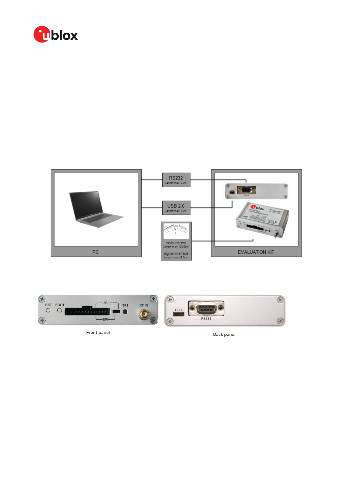
5.1 Interface connection
The EVK-M91 supports all three communication interfaces: UART, I2C and SPI. For connecting the
EVK to a PC, use a standard SUBD-9 cable or the included USB Type-C cable depending on the
interface in use.
The u-blox M9 GNSS receiver has a USB interface which allows direct communication to the receiver
by USB.
Additional measurement equipment can be connected to the front connector.
Figure 1: Connecting the unit for power supply and communication
Figure 2 shows the front and the back panel of the EVK-M91 evaluation unit.
Figure 2: EVK-M91 front and back panels
5.1.1 Interface switch
Use the interface switch on the front panel to choose between I2C/UART and SPI communication
ports. You must reset the unit by pressing the RST button after the interface switch setting has
been changed.
1. I2C – In this selection the EVK operates with the UART (RS232 – back panel or the 3.0 V level
TXD (MISO), RXD (MOSI) at the front panel). Also the communication via 3.0 V I2C interface is
selected.
UBX-19056858 - R03
C1-Public
5 Device description Page 10 of 26
Page 11

EVK-M91-User guide
2. SPI – In this selection the EVK operates only with the SPI interface. RS232 is switched off.
5.1.2 USB
The USB Type-C connector on the evaluation board can be used for both power supply and
communication. The easiest way to evaluate the EVK-M91 operation is to connect the EVK to a PC by
the USB-C 2.0 cable and then to use the u-center to configure and monitor the GNSS functions. The
USB connector has a direct connection to the u-blox M9 receiver, which enables the USB interface
to be used as a communication interface as well.
When the board is connected to the PC, Windows creates a virtual COM port to the PC. This
newly created virtual COM port needs then to be selected on the u-center application. The USB
communication speed is by default set to 38400 baud. EVK-M91 supports speeds up to 921600
baud.
5.1.3 UART
The evaluation unit includes two options for the UART connection, one is an RS232 port for serial
communication with the PC and the other one is the 14-pin connector.
5.1.3.1 RS232
Connect using a straight RS232 serial cable with male and female connectors to the port on your
PC. The maximum cable length is < 3.0 meters. To configure the RS232 port, use the CFG-VALSET
command and select CFG-UART1 Configuration group in the u-center application. The maximum
operating baud rate is 921600 Bd. If you are using a USB to RS232 adaptor cable, you can connect
it directly to the evaluation kit RS232 port.
The 9-pin RS232 female connector is assigned as listed below:
Pin Nr. Assignment
1 & 6 Time pulse
2 TXD/SPI_MISO, GNSS Transmit Data, serial data to external
3 RXD/SPI_MOSI, GNSS Receive Data, serial data from
4 EXTINT
5 GND
7, 8 & 9 not connected
Table 4: EVK-M91 RS232 connector pin description
device
external device
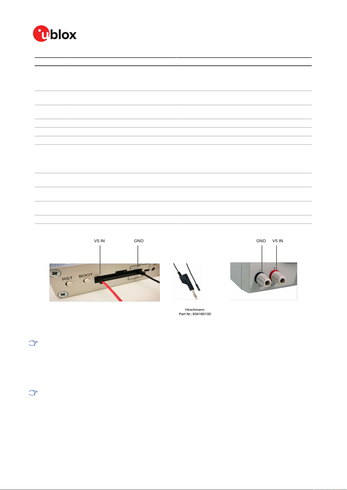
5.1.3.2 14-pin connector
There is a 14-pin connector on the EVK-M91. It provides PIO, interfaces and supply options. All these
pins are ESD protected. The 14-pin connector can be used for interfacing with UART, SPI, I2C and
for evaluating other advanced scenarios.
Pin Nr. Pin name I/O Level Description
14 V5 IN I 4.75-5.25 V Power input – can be used instead of USB
13 GNSS I2 O 5.0 V Supply current measurement (total current) node 2. See
12 GNSS I1 O 5.0 V Supply current measurement (total current) node 1.
description for pin 12.
Connected to 5 V power supply. Current measured over a
1 Ω 1% resistor between pins 12 (GNSS I1) and 11 (GNSS
I2). Pin 12 (GNSS I1) is at higher potential. NOTE: the total
current includes also LNA and SPI flash.
UBX-19056858 - R03
C1-Public
5 Device description Page 11 of 26
Page 12
EVK-M91-User guide
Pin Nr. Pin name I/O Level Description
11 BCKP I1 O 3.0 V Backup supply current measurement node 1. Connected to
10 BCKP I2 O 3.0 V Backup supply current measurement node 2. See
9 VBCKP IN I 3.0 V Backup power supply input – optional input for testing
8 TIMEPULSE O 3.0 V Time pulse signal
7 EXTINT I 3.0 V External interrupt, can be used for time aiding
6 PIO8 I/O 3.0 V Generic input/output (PIO8)
5 SDA/CS I/O 3.0 V
4 SCL/SCK I 3.0 V Clock input. Can also be used as generic input/output
3 TxD/MISO O 3.0 V Serial port transmit or SPI slave transmit, operation
2 RxD/MOSI I 3.0 V Serial port receive or SPI slave receive, operation selected
1 GND I – Recommended common ground pin
Table 5: EVK-M91 14 pin connector pin description
backup supply (super capacitor). Current measured over a
100 Ω 1% resistor between pins 11 (BCKP I1) and 10 (BCKP
I2). Pin 11 (BCKP I1) is at higher potential.
description for pin 11.
backup operation
If slide the interface switch on I2C, then I2C interface
selected; Function: data input / output
If slide the interface switch on SPI, then SPI interface
selected; chip select input – LOW ACTIVE
(PIO4).
selected by interface switch
by interface switch
Figure 3: EVK-M91 example 5 V DC power supply
When using the 3.0 V digital interfaces with your application (e.g. SPI or I2C), a cable length
less than 25 cm is recommended.
5.1.4 SPI
The SPI interface pins are available on 14-pin connector, see section 14-pin connector for more
information.
If using the SPI interface, the Interface switch must be set to "SPI".
5.1.5 I2C
The 14-pin connector contains pins for evaluating I2C bus communication. If using I2C, the Interface
switch must be set to "I2C".
UBX-19056858 - R03
C1-Public
5 Device description Page 12 of 26
Page 13

EVK-M91-User guide
By default, the optional I2C pull-up resistors are not populated on the EVK board. The u-blox M9
GNSS receiver already contains internal pull-up resistors for normal use. If fast communication
speed with long cable length is needed, the optional pull-up resistors can be placed to the reserved
location on the EVK board.
5.2 GNSS input signal
To evaluate the GNSS reception, the GNSS signal must be supplied to the antenna input SMA
connector of the evaluation board. EVK-M91 evaluation kit includes a GPS / Galileo / GLONASS /
BeiDou antenna with a 3.0 m cable. It is possible to connect various active and passive GNSS
antennas with SMA connectors or provide a signal from a recorded or simulated GNSS RF source
to the antenna input.
Refer to the NEO-M9N System Integration Manual [8] for more GNSS antenna / signal
related information and recommendation.
The characterization and certifications for EVK-M91 are applicable only with the active
GNSS antenna included in the evaluation kit (or comparable).
5.2.1 Antenna connector
An SMA female connector is available on the front side (see Figure 2) of the evaluation unit for
connecting an active or a passive antenna. The RF path on EVK-M91 contains an LNA and a SAW
filter having 3.0 V DC voltage in the RF input. The recommended maximum antenna supply current
for active antennas is 40 mA and is limited by the internal antenna short circuit detection feature.
Please refer to [9] for more details. In addition to internal short circuit antenna detection feature,
a hardware short circuit protection limits the maximum current to 100 mA. This pin is also ESD
protected.
5.3 Time pulse
u-blox receivers include a time pulse function providing clock pulses with a configurable pulse period,
pulse length and polarity (rising or falling edge). Check the NEO-M9N Data sheet [7] for detailed
specifications of configurable values.
The time pulse signal is available at the 14-pin and RS232 connectors. In addition, time pulse signal
is connected to the LED on the front panel of the unit.
5.4 Reset button
The RST button on the front panel resets the unit.
5.5 Safe boot button
This is used to set the unit in safe boot mode. In this mode the receiver executes only the minimal
functionality, such as updating new firmware into the SPI flash via UART. In order to set the receiver
in safe boot mode please follow these steps:
1. Press the BOOT button and hold it down
2. Press the RST button
3. Release the RST button
4. Release the BOOT button
5. If the UART interface has to be used, a training sequence has to be sent to the receiver
though u-center firmware update tool or custom message window. The training sequence is
UBX-19056858 - R03
C1-Public
5 Device description Page 13 of 26
Page 14

EVK-M91-User guide
a transmission of 0x55 0x55 at the baud rate of 9600 Bd. Wait for at least 100 milliseconds
before the interface is ready to accept commands.
5.6 LED
On the front panel of the unit, a single blue LED shows the time pulse signal as well as the status
that device is supplied. The LED starts flashing one pulse per second during a GNSS fix. If there is
no GNSS fix, the LED will only be lit, without flashing.
5.7 Flash
EVK-M91 has an SPI flash that is connected to the u-blox M9 receiver. By default it can be used to:
• Store the current configuration permanently
• Save data logging results
•
Hold AssistNow™ Offline and AssistNow™ Autonomous data
EVK-M91 has a 16-Mbit flash. However, only 5 Mbit of this is available for application use. The
remainder of the space is reserved for other features.
5.8 Super capacitor
The evaluation board includes a super capacitor to supply the backup power domain of the EVK-M91
and is charged whenever there is a power supply available, either via USB or the 14 pins connector.
The super capacitor provides backup power directly to the EVK-M91 V_BCKP power input in case of
no other V_BACKUP power supply is provided. When this 1 F capacitor is fully charged to 3.0 V, it can
provide backup power for about 10 hours (t=C*U/I=1*(3.0-1.65)/36uA=37,500 seconds -> 10 hours).
The 3.0 V V_BACKUP power supply can be used to provide power for any needed period of time while
evaluating for very long backup periods.
5.9 EXTINT
On the EVK-M91, the EXTINT signal is available on 14-pin connector, see sections 14-pin connector
and RS232 for more information.
UBX-19056858 - R03
C1-Public
5 Device description Page 14 of 26
Page 15

EVK-M91-User guide
6 Current measurement
6.1 GNSS current
At start-up, the receiver starts in acquisition state to search for available satellites and to download
GNSS orbital data, i.e., ephemeris and almanac. Once the data has been downloaded, the receiver
enters tracking state. In continuous operation, the receiver typically remains in tracking state once
entering it. The current consumption reduces when the receiver enters the tracking state. The time
required to enter tracking mode can be reduced by downloading aiding data from the AssistNow
Online service.
On EVK-M91, the main supply voltage for the u-blox M9 GNSS receiver is 3.0 V. The internal DCDC
converter is enabled to reduce power consumption. To measure the total GNSS supply current with
EVK-M91, follow these steps:
1. Power up EVK-M91.
2. Connect a true RMS voltmeter across GNSS I1 (pin 12) and GNSS I2 (pin 13) of the 14-pin
connector.
3. Read the voltage (and average if necessary) on the voltmeter and convert to current (1 mV
equals 1 mA).
4. Perform the test with good signals and clear sky view to ensure that the receiver can acquire
the satellite signals.
™
The total GNSS current includes the internal LNA, SPI flash and TCXO.
6.2 Backup current
To measure the backup current with EVK-M91, follow these steps:
1. Connect a true RMS voltmeter across BCKP I1 (pin 11) and BCKP I2 (pin 10) of the 14-pin
connector.
2. Remove power supply (USB cable or other external power supply).
3. Read the voltage (and average if necessary) on the voltmeter and convert to current (1 mV
equals 10 µA).
UBX-19056858 - R03
C1-Public
6 Current measurement Page 15 of 26
Page 16

EVK-M91-User guide
7 Block diagram
EVK-M91 block diagram providing an overview on supply voltages and interfaces is shown in Figure
4.
Figure 4: EVK-M91 block diagram
UBX-19056858 - R03
C1-Public
7 Block diagram Page 16 of 26
Page 17

8 Board layout
8.1 PCB version B
The PCB for EVK-M91 is shown in Figure 5.
EVK-M91-User guide
Figure 5: EVK-M91 PCB
UBX-19056858 - R03
C1-Public
8 Board layout Page 17 of 26
Page 18

EVK-M91-User guide
9 Firmware update
This section shows how to update the firmware on EVK-M91 if required.
The EVK-M91 is delivered with the latest version of firmware. However, as newer versions may
become available during the lifetime of the product, you might need to update the firmware.
To update the firmware, connect via USB to u-center and poll UBX-MON-VER to view the installed
firmware, as shown in Figure 6.
Figure 6: Checking EVK-M91 firmware version from u-center
To upload a new firmware follow the instructions below:
1. Select Tools > Firmware Update…. The firmware update window will appear as shown in
Figure 7.
Figure 7: Firmware update tool
2. Select the firmware image by clicking the ellipsis button next to Firmware image.
UBX-19056858 - R03
C1-Public
9 Firmware update Page 18 of 26
Page 19

EVK-M91-User guide
3. Select Use this baudrate for update option and choose a higher baudrate, i.e., 460800 to
make the firmware update faster.
4. Click GO.
5. Poll UBX-MON-VER again to verify the updated firmware.
UBX-19056858 - R03
C1-Public
9 Firmware update Page 19 of 26
Page 20

EVK-M91-User guide
10 Troubleshooting
My application (e.g. u-center) does not receive all messages
When using UART, make sure the baud rate is sufficient. If the baud rate is insufficient, GNSS
receivers based on u-blox M9 GNSS technology will skip excessive messages. Some serial port cards/
adapters (e.g. USB to RS232 converter) frequently generate errors. If a communication error occurs
while u-center receives a message, the message will be discarded.
My application (e.g. u-center) loses the connection to the GNSS receiver
u-blox M9 positioning technology and u-center have an autobauding feature. If frequent
communication errors occur (e.g. due to problems with the serial port), the connection may be lost.
This happens because u-center and the GNSS receiver both autonomously try to adjust the baud
rate. Do not enable the u-center autobauding feature if the GNSS receiver has the autobauding flag
enabled.
Some COM ports are not shown in the port list of my application (e.g. u-center)
Only the COM ports that are available on your computer will show up in the COM port drop down list.
If a COM port is gray, another application running on this computer is using it.
EVK-M91 does not work properly when connected to a GNSS simulator
When using EVK-M91 together with a GNSS simulator, please pay attention to proper handling of
the EVK. A GNSS receiver is designed for real-life use, i.e., time is always moving forward. When using
a GNSS simulator scenarios, the scenario time can be in the past resulting in the receiver to jump
backwards in time. This can have serious side effects on the performance of GNSS receivers.
The solution is to configure the GPS week rollover value to a week number preceding the date in
GNSS simulator scenario. For example, setting the GPS week number to 1200 (corresponding to Jan
2003) allows running simulator scenarios taking place after this date. Please refer to Figure 8 for
how to set the GPS week number with u-center GNSS evaluation software. In addition, always issue
a Cold start command before every simulator test to avoid receiver confusion due to the time jumps.
UBX-19056858 - R03
C1-Public
10 Troubleshooting Page 20 of 26
Page 21

EVK-M91-User guide
Figure 8: Setting GPS week number with u-center GNSS evaluation software
UBX-19056858 - R03
C1-Public
10 Troubleshooting Page 21 of 26
Page 22

EVK-M91-User guide
11 Common evaluation pitfalls
• Parameters may have the same name but a different definition. GNSS receivers may have a
similar size, price and power consumption but can still have different functionalities (e.g. no
support for passive antennas, different temperature range). Also, the definitions of Hot, Warm,
and Cold Start times may differ between suppliers.
• Verify design-critical parameters; do not base a decision on unconfirmed numbers from
datasheets.
• Try to use identical or at least similar settings when comparing the GNSS performance of
different receivers.
• Data, which has not been recorded at the same time and the same place, should not be
compared. The satellite constellation, the number of visible satellites and the sky view might
have been different.
• Do not compare momentary measurements. GNSS is a non-deterministic system. The satellite
constellation changes constantly. Atmospheric effects (i.e. dawn and dusk) have an impact
on signal travel time. The position of the GNSS receiver is typically not the same between two
tests. Comparative tests should therefore be conducted in parallel by using one antenna and a
signal splitter; statistical tests shall be run for 24 hours.
• Monitor the carrier-to-noise-ratio (C/N0). The average C/N0 of the high elevation satellites
should be between 40 dBHz and about 50 dBHz. A low C/N0 will result in a prolonged TTFF and
more position drift.
• When comparing side-by-side receivers, make sure that all receivers have the same signal
levels. The best way to achieve this is by using a signal splitter. Comparing results measured
with different antenna types (with different sensitivity) will lead to incorrect conclusions.
• Try to feed the same signal to all receivers in parallel (i.e. through a splitter); the receivers
will otherwise not have the same sky view. Even small differences can have an impact on the
speed, accuracy, and power consumption. One additional satellite can lead to a lower dilution of
precision (DOP), less position drift, and lower power consumption.
• When doing reacquisition tests, cover the antenna in order to block the sky view. Do not
unplug the antenna since the u-blox M9 positioning technology continuously performs a noise
calibration on idle channels.
• The Interface Switch is used to select “UART/I2C” or “SPI” port. If the receiver is set to “UART/
I2C” mode and configuration is saved by sending the CFG-CFG save command, all input and
output protocols for SPI are disabled. Powering up the EVK in “SPI” mode will result in the
receiver starting with all SPI input and output protocols disabled. Since SPI input has also been
disabled, it is impossible to recover using the SPI interface. Powering up in “UART/I2C” mode
and sending a CFG-CFG clear command restores the SPI port defaults, which makes SPI usable
again.
UBX-19056858 - R03
C1-Public
11 Common evaluation pitfalls Page 22 of 26
Page 23

EVK-M91-User guide
Related documents
[1] UBX-M9140-KA Data sheet, doc. no. UBX-18021372 (NDA required)
[2] UBX-M9140-KA Integration manual, doc. no. UBX-19041089 (NDA required)
[3] UBX-M9140-KA Interface description, doc. no. UBX-19042181 (NDA required)
[4] UBX-M9140-KB Data sheet, doc. no. UBX-18020412 (NDA required)
[5] UBX-M9140-KB Integration manual, doc. no. UBX-18020542 (NDA required)
[6] UBX-M9140-KB Interface description, doc. no. UBX-19039383 (NDA required)
[7] NEO-M9N Data sheet, doc. no. UBX-19014285
[8] NEO-M9N Integration manual, doc. no. UBX-19014286
[9] NEO-M9N Interface description, doc. no. UBX-19035940
[10] u-center User guide, doc. no. UBX-13005250
[11] Information technology equipment – Safety Standard IEC 62368-1:2018
For regular updates to u-blox documentation and to receive product change notifications
please register at www.u-blox.com.
UBX-19056858 - R03
C1-Public
Related documents Page 23 of 26
Page 24

Revision history
Revision Date Name Status / comments
R01 23-Dec-2019 msul, rmak Initial release
R02 03-Apr-2020 msul
R03 03-Nov-2020 msul
Updated FW version to SPG 4.03 in page 2, updated RS232 output voltage
level to +/-5 V in specifications section 2, updated safety precautions in
section 2.1, updated short-circuit threshold value to 40mA in section 4.2.1,
added antenna supervisor part on the block diagram in figure 4, updated
figure 5 for PCB version B in section 7. Added firmware update section 8,
added glossary in appendix section.
Updated FW version to SPG 4.04 in page 2, added approvals section 4,
updated figure in firmware update section 9.
EVK-M91-User guide
UBX-19056858 - R03
C1-Public
Revision history Page 24 of 26
Page 25

Appendix
A Glossary
Abbreviation Definition
BeiDou Chinese navigation satellite system
EVK Evaluation Kit
I2C Inter-Integrated Circuit bus
ESD Electrostatic Discharge
Galileo European navigation satellite system
GLONASS Russian navigation satellite system
GND Ground
GNSS Global Navigation Satellite System
GPS Global Positioning System
IEC International Electrotechnical Commission
PCB Printed Circuit Board
RF Radio frequency
UBX u-blox
QZSS Quasi-Zenith Satellite System
EVK-M91-User guide
UBX-19056858 - R03
C1-Public
Appendix Page 25 of 26
Page 26

EVK-M91-User guide
Contact
For complete contact information visit us at www.u-blox.com.
u-blox Offices
North, Central and South America Headquarters Asia, Australia, Pacific
u-blox America, Inc. u-blox AG u-blox Singapore Pte. Ltd.
Phone: +1 703 483 3180 Phone: +41 44 722 74 44 Phone: +65 6734 3811
E-mail: info_us@u-blox.com E-mail: info@u-blox.com E-mail: info_ap@u-blox.com
Support: support@u-blox.com Support: support_ap@u-blox.com
Regional Office West Coast Regional Office Australia
Phone: +1 408 573 3640 Phone: +61 2 8448 2016
E-mail: info_us@u-blox.com E-mail: info_anz@u-blox.com
Support: support_ap@u-blox.com
Technical Support Regional Office China (Beijing)
Phone: +1 703 483 3185 Phone: +86 10 68 133 545
E-mail: support_us@u-blox.com E-mail: info_cn@u-blox.com
Support: support_cn@u-blox.com
Regional Office China (Chongqing)
Phone: +86 23 6815 1588
E-mail: info_cn@u-blox.com
Support: support_cn@u-blox.com
Regional Office China (Shanghai)
Phone: +86 21 6090 4832
E-mail: info_cn@u-blox.com
Support: support_cn@u-blox.com
Regional Office China (Shenzhen)
Phone: +86 755 8627 1083
E-mail: info_cn@u-blox.com
Support: support_cn@u-blox.com
Regional Office India
Phone: +91 80 4050 9200
E-mail: info_in@u-blox.com
Support: support_in@u-blox.com
Regional Office Japan (Osaka)
Phone: +81 6 6941 3660
E-mail: info_jp@u-blox.com
Support: support_jp@u-blox.com
Regional Office Japan (Tokyo)
Phone: +81 3 5775 3850
E-mail: info_jp@u-blox.com
Support: support_jp@u-blox.com
Regional Office Korea
Phone: +82 2 542 0861
E-mail: info_kr@u-blox.com
Support: support_kr@u-blox.com
Regional Office Taiwan
Phone: +886 2 2657 1090
E-mail: info_tw@u-blox.com
Support: support_tw@u-blox.com
Europe, Middle East, Africa
UBX-19056858 - R03
C1-Public
Page 26 of 26
 Loading...