

Page 1

o explains the potential impact on
EVA-M8
TCXO-to-crystal migration guide
Application note
Abstract
This document provides options and guidelines for migrating the EVA-M8Q TCXO-based SiP module
to EVA-M8M crystal-based SiP module. The application note als
GNSS performance and other possible hardware/firmware concerns.
www.u-blox.com
UBX-20052988 - R02
C1-Public
Page 2

EVA-M8 - Application note
u-blox or third parties may hold intellectual property rights in the products, names, logos and designs included in this
document. Copying,
permitted with the express written permission of u
The information contained herein is provided “as is” and u
implied, is given, including but not limited
purpose of the information. This document may be revised by u
documents, visit www.u
Copyright © u
Document information
Title EVA-M8
Subtitle TCXO-to-crystal migration guide
Document type Application note
Document number UBX-20052988
Revision and date R02 11-Feb-2021
Disclosure restriction C1-Public
UBX-20052988 - R02 Document information Page 2 of 19
C1-Public
reproduction, modification or disclosure to third parties of this document or any part thereof is only
-blox.
-blox assumes no liability for its use. No warranty, either express or
to, with respect to the accuracy, correctness, reliability and fitness for a particular
-blox at any time without notice. For the most recent
-blox.com.
-blox AG.
Page 3

EVA-M8 - Application note
Contents
Document information ................................................................................................................................ 2
Contents .......................................................................................................................................................... 3
1. Introduction ............................................................................................................................................. 4
2. Migration guideline ............................................................................................................................... 5
2.1 EVA-M8 (Q/M) comparison ....................................................................................................................... 5
2.2 RF design ...................................................................................................................................................... 5
2.3 Power requirements ................................................................................................................................... 6
2.4 Real-time clock (RTC) ................................................................................................................................. 6
2.5 VCC_IO monitor ........................................................................................................................................... 7
2.6 Temperature ................................................................................................................................................ 7
2.7 Performance ................................................................................................................................................. 8
Startup sensitivity and TTFF ........................................................................................................... 8
Road test performance analysis ....................................................................................................11
3. Conclusion ............................................................................................................................................. 17
Related documentation ........................................................................................................................... 18
Revision history .......................................................................................................................................... 18
Contact .......................................................................................................................................................... 19
UBX-20052988 - R02 Contents Page 3 of 19
C1-Public
Page 4

EVA-M8 - Application note
1. Introduction
This application note describes the migration procedure from EVA-M8Q to EVA-M8M.
The EVA-M8Q uses a TCXO, while the EVA-M8M uses a crystal. This small difference in the internal
oscillator leads to some considerations described in this document. For example, the frequency
tolerance of the crystal is wider than that of TCXO. This means that the receiver must search over a
wider range of frequencies, which will extend the time to first fix especially in weak signal conditions.
In addition, the crystal’s frequency is highly sensitive to temperature-variant environments.
Therefore, the operating temperature, as well as the heat dissipating systems on the board need to
be taken into consideration.
Nevertheless, with proper adjustments and design guidelines, crystal-based GNSS receivers can
achieve very similar performance to a TCXO-based solution, and are thus worth considering as an
alternative to many applications.
UBX-20052988 - R02 Introduction Page 4 of 19
C1-Public
Page 5

EVA-M8 - Application note
recommended.
mandatory.
Flash FW SPG 3.01
Flash FW SPG 3.01
OTP config.
VCC_IO monitor HIGH
VCC_IO monitor LOW
2. Migration guideline
2.1 EVA-M8 (Q/M) comparison
The table below summarizes the specifications to be considered during the migration.
Field Parameter EVA-M8Q EVA-M8M
HW Oscillator TCXO Crystal
RTC derived from osc. Not possible Possible
Interface config. Same Same
Pinout Same Same
RF design Front-end With passive antenna, an external LNA is
Out of band immunity Same Same
Temp. Storage temp. °(C) Max +85 Max +105
Thermal isolation
Power Req. Supply (Vcc & Vio) (V) [2.7 - 3.6] [1.65 - 3.6]
Supply current (mA)
SW backup current (mA) 2 0.02 0.02
HW backup current (mA) 2 0.015 0.015
Sensitivity
(GPS&GLO)
SW Firmware ROM SPG 3.01 /
Dynamic Tracking (dBm) -167 -164
TTFF (sec)
1
2
3
Optional Recommended
22 23
Same
With passive antenna, an external LNA is
Same
ROM SPG 3.01 /
Table 1: EVA-M8Q to EVA-M8M migration comparison (default mode: GPS & GLONASS including QZSS, SBAS)
☞ When migrating to crystal-based EVA-M8M module, make sure the receiver is not operated in
Galileo-only mode. Crystal variants are not suitable for Galileo-only operation due to worse
performance (TTFF, sensitivity).
2.2 RF design
For designs without an external LNA or using a passive antenna, it is mandatory to include an external
LNA before the EVA-M8M module during the migration redesign, especially for those applications
under difficult GNSS visibility or poor reception. If, in addition, strong out-of-band jammers are close
to the GNSS antenna (for example, a cellular antenna), an additional SAW filter in front of the LNA
might be needed.
Applications with an active antenna or a present external LNA are exempt of RF front-end redesign.
Refer to the EVA-M8 Hardware Integration Manual [1] for more information about passive antenna
designs and recommended LNA/SAW components.
1
Mainly for applications where the GNSS module is under thermal activity on the board.
2
Single crystal feature disabled. Voltage supply = 3.0 V.
3
Cold and hot start under good GNSS visibility and using power levels of -130 dBm.
UBX-20052988 - R02 Migration guideline Page 5 of 19
C1-Public
Page 6

EVA-M8 - Application note
2.3 Power requirements
Crystal-based EVA-M8M allows a wider voltage supply range. This is due to the lower voltage required
by the crystal. Nevertheless, products have overlapping operational voltage ranges and similar
current consumption when using the RTC crystal.
The table below shows the expected current drawn of EVA-M8M and EVA-M8Q. More information is
available in the EVA-M8 Data Sheet [2].
Parameter Symbol Conditions Module Typ
Max. supply current
4
Average
supply current
Backup battery
current
7
Iccp All 67 mA
6
VCC_IO =
VCC = 3 V
VCC_IO =
VCC = 3 V
VCC_IO =
VCC = 3 V
HW Backup mode,
VCC_IO =
EVA-M8M 25 19 mA
EVA-M8Q 26 20 mA
EVA-M8M 22 17 mA
EVA-M8Q 23 18 mA
EVA-M8M 5.3 4.7 mA
EVA-M8Q 6.2 5.7 mA
All 15 µA
5
Icc Acquisition
Icc Tracking
(Continuous mode)
Icc Tracking
(Power Save mode / 1
Hz)
I_BCKP
using the RTC crystal
VCC = 0 V
I_BCKP
using the 26 MHz
XTO in “single
crystal” operation
SW Backup current I_SWBCKP
using the RTC crystal
HW Backup mode,
VCC_IO =
VCC = 0 V
SW Backup mode,
VCC_IO =
EVA-M8M 100 µA
EVA-M8Q N/A8
All 20 µA
VCC = 3 V
I_SWBCKP
using the 26 MHz
XTO in “single
crystal” operation
SW Backup mode,
VCC_IO =
VCC = 3 V
EVA-M8M 105 µA
EVA-M8Q N/A9
Table 2: EVA-M8Q to EVA-M8M power requirements
GPS &
GLONASS
Typ
GPS / QZSS /SBAS
Max Units
2.4 Real-time clock (RTC)
In EVA-M8Q designs without RTC, the TCXO-to-crystal migration offers the option to enable the EVAM8M’s single crystal feature, which uses the crystal as RTC. The single crystal feature will increase
the hardware and software backup currents, but will considerably reduce hot and warm start times.
☞ Note that the single crystal mode increases the back-up current consumption 5 times, which
is a sensitive factor for battery-powered devices.
For more information about the single crystal feature, see EVA-8M / EVA-M8M Hardware Integration
Manual [1].
4
Use this figure to dimension maximum current capability of power supply. Measurement of this parameter with 1 Hz bandwidth.
5
Simulated constellation of 8 satellites is used. All signals are at -130 dBm. VCC= 3 V.
6
Average current from start-up until the first fix.
7
Use this figure to determine required battery capacity.
8
Not applicable, feature not supported.
9
Not applicable, feature not supported.
UBX-20052988 - R02 Migration guideline Page 6 of 19
C1-Public
Page 7

EVA-M8 - Application note
2.5 VCC_IO monitor
This section applies in case an external SQI flash memory is connected.
The EVA-M8 series has a configurable VCC_IO monitor threshold to ensure that the module will start
if the VCC_IO voltage is within the supply range of the SQI flash memory.
By default, this parameter, called “iomonCfg”, is set to 1.54 V in EVA-M8M for using a 1.8 V flash
memory, which is too low for designs with EVA-M8Q using a 3 V flash memory. Consequently, this
needs to be set accordingly in the eFuse (OTP memory).
If VCC_IO voltage 2.7 V to 3.0 V is used, send the following sequence to the module:
- B5 62 06 41 0C 00 00 00 03 1F 04 BA CF 67 FF 7F FF FF E5 95
If VCC_IO voltage 3.0 V to 3.6 V is used, send the following sequence to the module:
- B5 62 06 41 0C 00 00 00 03 1F 4F 22 4C 5C FF 7F 7F FF 8A 7C
☞ The command will permanently set this value and it cannot be reversed.
For more information about the IO monitor configuration, see the EVA-8M / EVA-M8M Hardware
Integration Manual [1].
2.6 Temperature
The frequency drift for crystals and TCXO oscillators is very dependent on the ambient temperature.
Although the receiver can correct such offset, it is recommended to avoid quick temperature changes.
As a brief explanation, a GNSS receiver can track satellite signals up to a certain high dynamic value,
which is defined as Delta frequency/ Delta time (Δf/Δt). As a result, a temperature change in a very
short time at the crystal will end in a very high dynamic, in the worst scenario losing phase lock.
Although both crystal and TCXO are highly sensitive to any quick temperature changes, due to the
wider frequency range of crystals compared to TCXO, special attention is needed for crystal-based
designs.
If the receiver is possibly placed under these conditions, it is highly recommended to isolate the
module by thermally minimizing the thermal conduction over the PCB and place the module far from
fans or other components with quick body temperature changes that can increase the board and
ambient temperature. Adding elements for heat dissipation between the receiver and other elements
as well as increasing the surface contact area of the board around stabilizes the temperature.
The effect of the temperature on the crystal can be seen in the Figure 1 below. u-blox crystal-based
modules can easily re-adjust the frequency drift for normal operation. It is important to mention that
all crystal oscillators qualified by u-blox pass extensive tests to ensure such smooth frequency drift
over full operation temperature range (-40 to +85 °C).
UBX-20052988 - R02 Migration guideline Page 7 of 19
C1-Public
Page 8

EVA-M8 - Application note
Figure 1: Temperature effect on crystal on various crystal-based modules
2.7 Performance
Startup sensitivity and TTFF
Crystal-based GNSS receivers are characterized as having a longer time to synchronize with GNSS
signals. The effect is more visible when the signals are weak and the GNSS visibility is poor.
Such behavior can be seen in Figure 2, where the times to fix of crystal-based EVA-M8M become
longer than those of TCXO-based EVA-M8Q as the GNSS signal power drops. (Note that the scale in
the horizontal axis for the signal power is not linear.)
☞ Note that the values in the horizontal axis are not linear. If all levels were present at the
horizontal axis, the curve would be plain until -140 dBm, where it would increase exponentially
with weaker signals.
UBX-20052988 - R02 Migration guideline Page 8 of 19
C1-Public
Page 9

EVA-M8 - Application note
Figure 2: TTFF vs. signal power for EVA-M8Q and EVA-M8M during cold starts10 (default mode: GPS & GLONASS including
QZSS, SBAS)
In general, a strong signal will give the shortest time to first fix. At room temperature (+25 °C), the
TTFF differences between the EVA-M8Q (orange line in Figure 2) and the EVA-M8M (blue line) grow
as the GNSS signal levels drop. Figure 2 shows that under a strong signals environment (signals with
active antenna), the TTFF is very similar for both TCXO and crystal-based EVA products.
The GNSS signal power levels above 43 dBHz (-130 dBm) are considered as strong signals. The cold
start results in Figure 2 show that the TTFF numbers of EVA-M8Q and EVA-M8M are still very close
to each other even at weaker signal condition of 33 dBHz (-140 dBm). Such Carrier-to-Noise ratio
(C/N0) levels should be achievable with good open-sky visibility (best to have the satellite at the
Zenith) using an active antenna.
If we compare TTFF at different operating temperatures, a small degradation is visible under very cold
environments for crystal-based EVA-M8M, as shown in Figure 3. As an example, a receiver which
starts at -35 °C will gradually increase the crystal temperature due to both components’ proximity
(self-heating), which results in an increase of the clock drift during the acquisition of the GNSS
signals. Again, the consequences associated are not relevant when GNSS signals are strong enough,
as can be seen in the figure below.
10
Results obtained in our test sites using a good LNA in front.
UBX-20052988 - R02 Migration guideline Page 9 of 19
C1-Public
Page 10

EVA-M8 - Application note
Figure 3: TTFF vs. signal power for EVA-M8M during cold starts at +25, -35, and +85 °C (default mode: GPS & GLONASS
including QZSS, SBAS)
For TCXO-based EVA-M8Q, the temperature dependency of the TTFF is quite small, as shown in
Figure 4. This result is expected as the TCXO frequency variation due to temperature is significantly
smaller than the frequency variation of the crystal.
UBX-20052988 - R02 Migration guideline Page 10 of 19
C1-Public
Page 11

EVA-M8 - Application note
Figure 4: TTFF vs. signal power for EVA-M8Q during cold starts at +25, -35, and +85 °C (default mode: GPS & GLONASS
including QZSS, SBAS)
As a summary, the longer TTFFs due to the crystal’s wider drift and extreme operating temperature
can be easily mitigated by using a good antenna or LNA. Under such good GNSS signal conditions, we
can predict a signal power level above -144 dBm, where both TCXO and crystal variants show similar
TTFF values. As mentioned in section 2.2, an external LNA is mandatory when using a passive
antenna with a crystal-based EVA-M8M.
Note that the following results have been obtained using GPS and GLO signals and using the default
configuration.
Road test performance analysis
Road tests show real behavior in dynamic scenarios. The road tests allow measuring the position
accuracy delivered by the receiver. The accuracy, calculated as the offset to the real position, is
showed in error percentiles for 2D and 3D coordinates.
Three different road tests have been carried out for both crystal and TCXO variants. The goal of these
tests is to assess the impact of different signal power levels and to see if the degradation is similar.
☞ The C/N0 value in the following figures and tables is the median of all GPS signals used for
tracking along the test.
☞ The test results are based on limited samples and should be considered as a reference.
UBX-20052988 - R02 Migration guideline Page 11 of 19
C1-Public
Page 12
EVA-M8 - Application note
2.7.2.1 Rural areas with good GNSS visibility
The test in a rural area is characterized as having excellent GNSS visibility most of the time,
alternating with weak signal areas where there are trees and small houses along the road.
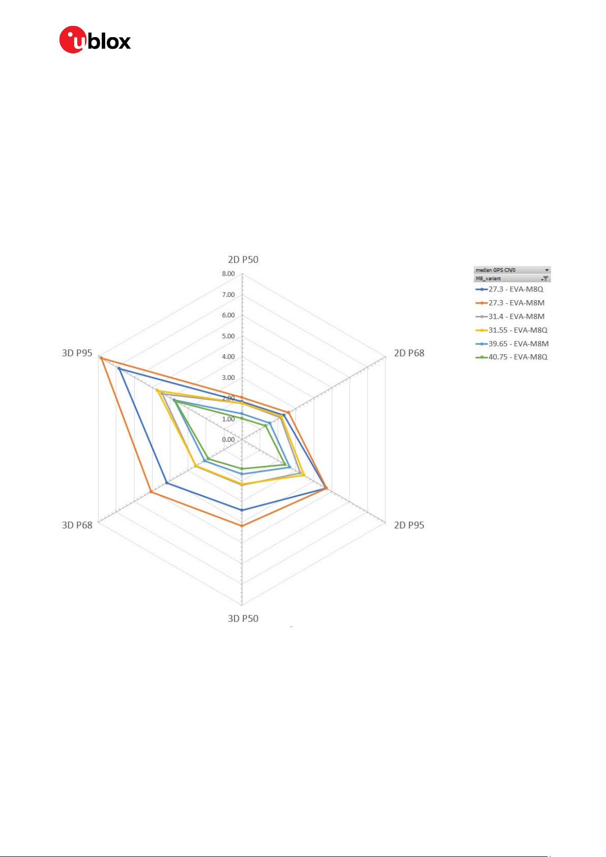
The figure below shows position accuracy for the EVA-M8Q and EVA-M8M on a radar plot under three
different signal power levels. The first one of these three represents designs with good signal
reception, where average C/N0 values for all GNSS signals tracked are around 40 dBHz, suitable for
designs using active or external LNA. The second one is with 8-9 dBHz weaker signal power, average
C/N0 around 31.5 dBHz. The last scenario with a signal around 27 dBHz represents applications with
very poor signal reception.
The goal is to compare the accuracy degradation of both TCXO and crystal-based EVA modules in
these three situations.
Figure 5: Position error in meters for EVA-M8Q and EVA-M8M in percentiles at 27.3, 31.5 and 40 dBHz in rural areas (default
mode: GPS and GLONASS including QZSS, SBAS)
The test results presented in Figure 5 show 6 curves that can be grouped into three. The two inner
ones represent accuracy under good signals, the two in the middle under weaker signals, and the outer
ones for the weakest scenario. The worst performance degradation of the crystal-based EVA-M8M
appears when the average signal levels are dropped to below 30 dBHz. For signals above that
“threshold”, the position accuracy and the degradation relation (Δerror/ Δsignal attenuation) are very
similar for both the TCXO-based EVA-M8Q and the crystal-based EVA-M8M. The accuracy values for
all three test scenarios are also represented in Table 3 below.
UBX-20052988 - R02 Migration guideline Page 12 of 19
C1-Public
Page 13
EVA-M8 - Application note
Values Weakest signal
27.3 dBHz
EVA-M8Q
2D P50 (m) 1.82 2.03 1.75 1.74 1.02 1.27
2D P68 (m) 2.36 2.60 2.21 2.13 1.33 1.61
2D P95 (m) 4.70 4.70 3.45 3.24 2.42 2.64
3D P50 (m) 3.42 4.19 2.14 2.20 1.43 1.67
3D P68 (m) 4.19 5.06 2.56 2.58 1.86 2.02
3D P95 (m) 6.83 7.83 4.71 4.43 3.72 3.74
Table 3: Position error in percentiles for EVA-M8(Q/M) at different signal power levels in rural areas (default mode: GPS and
GLONASS including QZSS, SBAS)
27.3 dBHz
EVA-M8M
Weak signal
31.55 dBHz
EVA-M8Q
31.4 dBHz
EVA-M8M
Good signal
40.75 dBHz
EVA-M8Q
40.7 dBHz
EVA-M8M
2.7.2.2 Urban canyon with weak signal levels and multipath
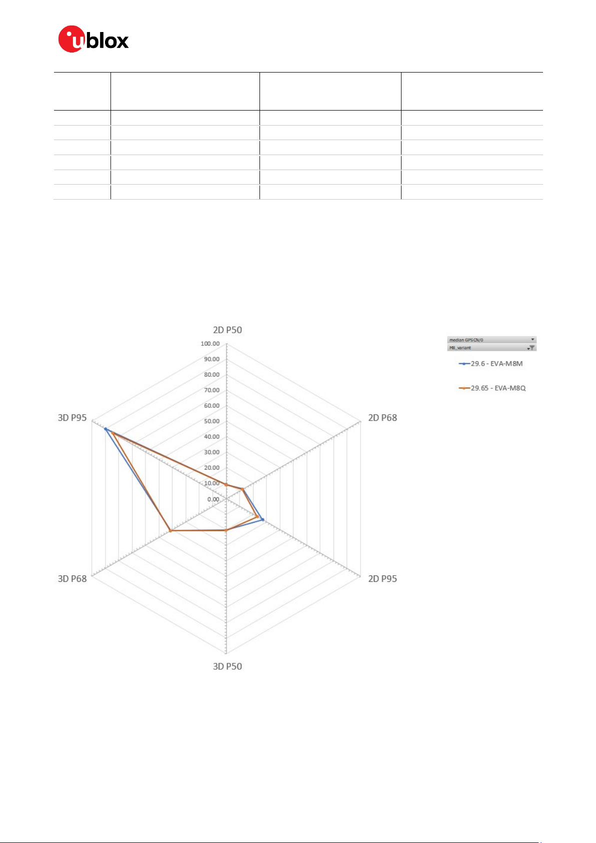
Figure 6 shows the position accuracy percentiles for EVA-M8Q and EVA-M8M modules in the urban
canyon environment. The test results in Figure 6 and Table 4 show that the position accuracy of the
TCXO-based EVA-M8Q and the crystal-based EVA-M8M is very similar in urban canyon with
extremely weak GNSS signal level (average C/N0 at 29.6 dBHz).
Figure 6: Position error in meters for EVA-M8Q and EVA-M8M in percentiles. Urban canyon with good and bad signal
reception conditions (default mode: GPS and GLONASS including QZSS, SBAS)
UBX-20052988 - R02 Migration guideline Page 13 of 19
C1-Public
Page 14

EVA-M8 - Application note
Values Weak signal
29.6 dBHz
EVA-M8Q
2D P50 (m) 9.07 8.89
2D P68 (m) 12.34 12.07
2D P95 (m) 27.19 23.20
3D P50 (m) 20.41 20.46
3D P68 (m) 41.45 41.56
3D P95 (m) 90.06 84.70
Table 4: Position error in percentiles for EVA-M8Q and EVA-M8M at weak signal power levels in urban canyon scenario
(default mode: GPS and GLONASS including QZSS, SBAS)
29.65 dBHz
EVA-M8M
Note that although the position errors are very big for all EVA modules, such performance is expected
for all standard precision receivers under such a particularly challenging environment (poor GNSS
visibility and high multipath effect). The real track followed is seen in the Figure 7 Error! Reference
source not found..
Figure 7: Scenario used for “Urban canyon” to compare performance between TCXO and crystal variants
2.7.2.3 Highway road test
Finally, a highway scenario has been used in the road test, under good GNSS signal and weak signal
conditions. In this case, the receiver calculates a position where conditions change rapidly on a
highway due to the car speed. Figure 8 captures a part of the drive and gives a good representation of
the test conditions.
UBX-20052988 - R02 Migration guideline Page 14 of 19
C1-Public
Page 15

EVA-M8 - Application note
Figure 8: Part of the “Highway” scenario used and track of the receivers
The higher speed is more challenging for GNSS receivers due to the tracking loops. The highway
scenario means the tracking is more difficult. Thus, the degradation of the signal levels has a larger
influence on the position accuracy. The active antennas will significantly help the GNSS receiver
performance here.
Figure 9: Position error in meters for EVA-M8Q and EVA-M8M in percentiles. Highway with strong and weak signal reception
conditions (default mode: GPS and GLONASS including QZSS, SBAS)
UBX-20052988 - R02 Migration guideline Page 15 of 19
C1-Public
Page 16

EVA-M8 - Application note
Values Weak signal
28.5 dBHz
EVA-M8Q
2D P50 (m) 1.37 1.49 1.05 1.06
2D P68 (m) 1.67 1.77 1.25 1.24
2D P95 (m) 2.77 2.80 2.15 2.00
3D P50 (m) 4.03 4.01 1.58 1.61
3D P68 (m) 4.66 4.68 1.88 1.86
3D P95 (m) 6.44 6.36 2.68 2.57
Table 5: Position error in percentiles for EVA-M8Q and EVA-M8M at different signal power levels in highway scenario (default
mode: GPS and GLONASS including QZSS, SBAS)
28.5 dBHz
EVA-M8M
Good signal
41.85 dBHz
EVA-M8Q
41.9 dBHz
EVA-M8M
Highway test results shown in Figure 9 and Table 5 demonstrate once again that the crystal-based
EVA-M8M has very similar position accuracy compared to the TCXO-based EVA-M8Q under both
weak and good GNSS signal conditions on highway.
UBX-20052988 - R02 Migration guideline Page 16 of 19
C1-Public
Page 17

EVA-M8 - Application note
3. Conclusion
From startup sensitivity and TTFF test (section 2.7.1) and road tests (section 2.7.2), we can see that
for customers using an external LNA or an active antenna in current designs, there should be no issue
when switching from TCXO-based EVA-M8Q to crystal-based EVA-M8M.
Large and well-designed passive patch antennas, external LNA or active antennas can work perfectly
well with u-blox EVA-M8M receivers despite the minimal performance differences between the crystal
and the TCXO variant. EVA-M8M is a good crystal-based solution for applications where operation
with a weak signal is not necessary.
UBX-20052988 - R02 Conclusion Page 17 of 19
C1-Public
Page 18

EVA-M8 - Application note
Related documentation
[1] EVA-8M / EVA-M8 Hardware integration manual, UBX-16010593
[2] EVA-M8 Data sheet, UBX-16014189
Revision history
Revision Date Name Comments
R01 14-Dec-2020 cbib, imar Initial release
R02 11-Feb-2021 imar
Minor updates in Figure 2, Figure 3 and Figure 4 (Startup sensitivity and
TTFF plots). Added section 2.7.2 (road test data).
UBX-20052988 - R02 Conclusion Page 18 of 19
C1-Public
Page 19

EVA-M8 - Application note
Contact
For complete contact information, visit us at www.u-blox.com.
u-blox Offices
North, Central and South America
u-blox America, Inc.
Phone: +1 703 483 3180
E-mail: info_us@u-blox.com
Regional Office West Coast:
Phone: +1 408 573 3640
E-mail: info_us@u-blox.com
Technical Support:
Phone: +1 703 483 3185
E-mail: support@u-blox.com
Headquarters
Europe, Middle East, Africa
u-blox AG
Phone: +41 44 722 74 44
E-mail: info@u-blox.com
Support: support@u-blox.com
Asia, Australia, Pacific
u-blox Singapore Pte. Ltd.
Phone: +65 6734 3811
E-mail: info_ap@u-blox.com
Support: support_ap@u-blox.com
Regional Office Australia:
Phone: +61 3 9566 7255
E-mail: info_anz@u-blox.com
Support: support_ap@u-blox.com
Regional Office China (Beijing):
Phone: +86 10 68 133 545
E-mail: info_cn@u-blox.com
Support: support_cn@u-blox.com
Regional Office China (Chongqing):
Phone: +86 23 6815 1588
E-mail: info_cn@u-blox.com
Support: support_cn@u-blox.com
Regional Office China (Shanghai):
Phone: +86 21 6090 4832
E-mail: info_cn@u-blox.com
Support: support_cn@u-blox.com
Regional Office China (Shenzhen):
Phone: +86 755 8627 1083
E-mail: info_cn@u-blox.com
Support: support_cn@u-blox.com
Regional Office India:
Phone: +91 80 405 092 00
E-mail: info_in@u-blox.com
Support: support_in@u-blox.com
Regional Office Japan (Osaka):
Phone: +81 6 6941 3660
E-mail: info_jp@u-blox.com
Support: support_jp@u-blox.com
Regional Office Japan (Tokyo):
Phone: +81 3 5775 3850
E-mail: info_jp@u-blox.com
Support: support_jp@u-blox.com
Regional Office Korea:
Phone: +82 2 542 0861
E-mail: info_kr@u-blox.com
Support: support_kr@u-blox.com
Regional Office Taiwan:
Phone: +886 2 2657 1090
E-mail: info_tw@u-blox.com
Support: support_tw@u-blox.com
UBX-20052988 - R02 Conclusion Page 19 of 19
C1-Public
 Loading...