

Page 1

Abstract
Description of how to update the firmware on u-blox cellular modules using EasyFlash, FOAT (over
AT commands), and the Firmware Install command.
www.u-blox.com
UBX-13001845 - R18
Cellular module firmware
update
Using EasyFlash, FOAT and Firmware Install command
Application note
Page 2

Cellular module firmware update - Application note
Title
Cellular module firmware update
Subtitle
Using EasyFlash, FOAT and Firmware Install command
Document type
Application note
Document number
UBX-13001845
Revision and date
R18
15-May-2020
Disclosure restriction
Product status
Corresponding content status
Functional sample
Draft
For functional testing. Revised and supplementary data will be published later.
In development /
Prototype
Objective specification
Target values. Revised and supplementary data will be published later.
Engineering sample
Advance information
Data based on early testing. Revised and supplementary data will be published later.
Initial production
Early production information
Data from product verification. Revised and supplementary data may be published later.
Mass production /
End of life
Production information
Document contains the final product specification.
Product name
LEON-G1 series
SARA-G3 series
SARA-U2 series
LISA-U2 series
TOBY-L2 series
MPCI-L2 series
TOBY-R2 series
LARA-R2 series
TOBY-L4 series
u-blox or third parties may hold intellectual property rights in the products, names, logos and designs included in this
document. Copying, reproduction, modification or disclosure to third parties of this document or any part thereof is only
permitted with the express written permission of u-blox.
The information contained herein is provided “as is” and u-blox assumes no liability for its use. No warranty, either express or
implied, is given, including but not limited to, with respect to the accuracy, correctness, reliability and fitness for a particular
purpose of the information. This document may be revised by u-blox at any time without notice. For the most recent
documents, visit www.u-blox.com.
Copyright © u-blox AG.
Document information
This document applies to the following products:
UBX-13001845 - R18 Page 2 of 43
Page 3

Cellular module firmware update - Application note
Contents
Document information ................................................................................................................................ 2
Contents .......................................................................................................................................................... 3
1 Introduction ............................................................................................................................................. 5
2 FW update ................................................................................................................................................ 6
3 EasyFlash ................................................................................................................................................. 8
3.1 FW download over UART or UART AUX .................................................................................................. 8
3.2 FW download over USB ............................................................................................................................. 11
3.3 FW download over USB (TOBY-L2, MPCI-L2 series only) ................................................................. 14
4 Firmware update Over AT commands (FOAT) ........................................................................... 16
4.1 TOBY-L2, MPCI-L2 series AT command syntax ................................................................................. 16
4.1.1 Defined values ................................................................................................................................... 16
4.1.2 Error result codes ............................................................................................................................. 18
4.2 LEON-G1, SARA-G3, LISA-U2, SARA-U2, TOBY-R2, LARA-R2 series AT command syntax..... 18
4.2.1 Defined values ....................................................................................................................................21
4.2.2 Error result codes ..............................................................................................................................21
4.2.3 FW update procedure on LISA-U2 series ..................................................................................... 22
5 Firmware install (+UFWINSTALL) ................................................................................................. 23
5.1 Introduction ................................................................................................................................................ 23
5.2 LISA-U2, SARA-U2, LARA-R2, TOBY-R2 AT command syntax ....................................................... 23
5.2.1 Defined values ................................................................................................................................... 24
5.3 TOBY-L2, MPCI-L2 AT command syntax ............................................................................................. 25
5.3.1 Defined values ................................................................................................................................... 25
5.4 TOBY-L4 AT command syntax ............................................................................................................... 27
5.4.1 Defined values ................................................................................................................................... 27
5.5 Firmware Install specifications .............................................................................................................. 28
5.5.1 Generation of the “update file” ...................................................................................................... 28
5.5.2 Recovery mechanism ....................................................................................................................... 29
5.5.3 Installation performance ................................................................................................................. 29
5.5.4 Limitations ......................................................................................................................................... 29
Appendix ....................................................................................................................................................... 30
A Glossary ................................................................................................................................................. 30
B Firmware Install error result codes ................................................................................................ 31
B.1 LISA-U2, SARA-U2, LARA-R2, TOBY-R2, TOBY-L4 error result codes .......................................... 31
B.2 LISA-U2 final results codes ..................................................................................................................... 31
B.3 LARA-R2, TOBY-R2, SARA-U2 final result codes ............................................................................... 32
B.4 TOBY-L2, MPCI-L2 error result codes ................................................................................................... 33
B.5 TOBY-L4 final result codes ..................................................................................................................... 33
C FOTA demo application in m-center ............................................................................................ 34
C.1 FOTA: firmware downloading procedure ............................................................................................. 35
C.2 FOTA: firmware upgrading procedure .................................................................................................. 35
UBX-13001845 - R18 Page 3 of 43
Page 4

Cellular module firmware update - Application note
D FOAT/UFWUPD on a Linux system ............................................................................................... 36
D.1 Minicom ....................................................................................................................................................... 36
D.2 Sx command .............................................................................................................................................. 40
E Disabling the automatic notification of FW update ................................................................ 41
Related documents ................................................................................................................................... 42
Revision history .......................................................................................................................................... 42
Contact .......................................................................................................................................................... 43
UBX-13001845 - R18 Page 4 of 43
Page 5
Cellular module firmware update - Application note
EasyFlash
FOAT
FWINSTALL
UART
UART
AUX
USB
UART
UART
AUX
USB
SPI
UART
USB
TOBY-L2 series
1
2
2
MPCI-L2 series
2
TOBY-R2 series
LARA-R2 series
SARA-U2 series
3
3
LISA-U2 series
LISA-U2 "04", "82",
"83" product versions
SARA-G3 series
LEON-G1 series
TOBY-L4 series
“50” / ”51” product
versions
Command
Response
Description
AT+CGMR
11.40
OK
11.40 is an example of a modem version.
1
2
3
1 Introduction
This document briefly describes the firmware update mechanism for u-blox cellular modules.
The cellular firmware comprises three parts:
The module image
The module parameters
The module file system, which contains data that can be stored by the user (such as SMS/text
messages)
To completely update the firmware, it is necessary to download at least the module image and
parameters; the module file system is optional.
The three images are resident in dedicated areas of the flash memory.
☞ It is possible to update the firmware to a newer version or to revert to an older one.
☞ The LEON-G1 series the firmware can be reverted to an older firmware version only by using the
EasyFlash tool.
☞ The modules supporting OMA-DM and ODIS may automatically notify an OMA-DM server in the
event of a Firmware Update. See appendix E for more details.
Table 1: Firmware update procedures and interfaces used on u-blox cellular modules
The +CGMR AT command allows the user to verify the module modem version:
Not supported by TOBY-L2 "00" product versions
Not supported by MPCI-L2 "00" and "60" product versions and by TOBY-L2 "00", "50" and "60" product versions
Not supported by "00", "03", "53", "63", "73" product versions
UBX-13001845 - R18 Introduction Page 5 of 43
Page 6
Cellular module firmware update - Application note
Attribute
Description
Firmware
Firmware of the module
NVM
All parameters described in appendix B.2 of the u-blox AT command manual [1]
Profiles
All parameters described in appendix B.1 of the u-blox AT command manual [1]
FS (File System)
Place where the user can store his own files
Calibration data
Data not belonging to above listed attributes
Product
EasyFlash
FOAT (+UFWUPD) <filetype>=[0..2]
FOTA (+UFWINSTALL)
LEON-G1 series
NVM, profiles, FS
0:
1: FS
Not available
SARA-G3 series
NVM, profiles, FS
0: NVM, profiles
1: FS
Not available
LISA-U1 series
NVM, profiles, FS
0: NVM, profiles
1: NVM, profiles, FS
2: NVM, profiles, FS
Not available
LISA-U2 series
NVM, profiles, FS
0: NVM, profiles
1: NVM, profiles, FS
2: NVM, profiles, FS
Not available
SARA-U2 series
NVM, profiles, FS
0: NVM, profiles
1: NVM, profiles, FS
2: NVM, profiles, FS
NVM, profiles
2 FW update
This section introduces the different methods available to update the firmware of the cellular module.
For each method, it is shown what will change in the cellular module with respect to the previous FW
version. Table 2 shows the different attributes that may be affected by a firmware update.
Table 2: Attributes involved in FW update
The following methods are available for the FW update:
EasyFlash tool: EasyFlash is a tool for the Windows OS to download the firmware from a PC
through a module serial interface (USB or UART)
Firmware update over AT (FOAT) by means of the +UFWUPD AT command; the FOAT is a method
to update the firmware by transferring the related file from an external device (e.g. application
host processor) to the module through the AT interface
Firmware installation from a FS file. The firmware installation from a file is triggered by the
+UFWINSTALL AT command and uses a file stored in the module’s file system (e.g. a file retrieved
from a FOTA server). This procedure can be used as a final step for the FW update procedure
Table 3 lists the cellular series modules, and for each one, the three firmware update methods. Each
method lists the attributes that are changed after the firmware update (i.e. reset to the factoryprogrammed values). If an attribute is not listed, it means that it is not changed after the update
procedure.
For example, for LEON-G1 series modules using the FOAT (+UFWUPD) method with <filetype>=0, it
will not change the NVM, profiles and FS, while with <filetype>=1 it will not change the NVM and
profiles, but will change the FS.
☞ The “Firmware” attribute is not listed in Table 3, because it is updated in all the methods:
EasyFlash, +UFWUPD [with <filetype> 0 and 2], +UFWINSTALL.
UBX-13001845 - R18 FW update Page 6 of 43
Page 7

Cellular module firmware update - Application note
Product
EasyFlash
FOAT (+UFWUPD) <filetype>=[0..2]
FOTA (+UFWINSTALL)
LISA-U2
"04" / "82" / "83" product versions
NVM, profiles, FS
0: NVM, profiles
1: NVM, profiles, FS
2: NVM, profiles, FS
NVM, profiles
MPCI-L2 series
NVM, profiles, FS
NVM, profiles, FS
NVM, profiles, FS
TOBY-L2 series
NVM, profiles, FS
NVM, profiles, FS
NVM, profiles, FS
TOBY-R2 series
NVM, profiles, FS
0: NVM, profiles
1: NVM, profiles, FS
2: NVM, profiles, FS
NVM, profiles
LARA-R2 series
NVM, profiles, FS
0: NVM, profiles
1: NVM, profiles, FS
2: NVM, profiles, FS
NVM, profiles
TOBY-L4
“50” / “51” product version
NVM, profiles
Not Available
NVM, profiles
Table 3: Applicable products and attributes that will change when performing a FW update
UBX-13001845 - R18 FW update Page 7 of 43
Page 8

Cellular module firmware update - Application note
4
4
3 EasyFlash
☞ See Table 1 for the list of modules and interfaces supporting EasyFlash.
A proper setup file, e.g. EasyFlash_<xx.yy.zz>.exe, is used to install the executable file and the needed
components.
☞ EasyFlash has been tested on these operating systems: Windows XP, Windows Vista (32/64 bit),
Windows 7 (32/64 bit), Windows 8 (32/64 bit), Windows 8.1 (32/64 bit) (32/64 bit).
The EasyFlash tool requires a file in DOF format, which includes the firmware components (module
image, module parameters, module file system) that are needed to perform a FW update.
The FW update using EasyFlash requires a PC or Notebook. The EasyFlash executable file and the
.DOF file (containing the firmware version to update) must be stored in the same folder in the PC or
Notebook. Only one .DOF file should be in the folder.
For LEON-G1 and SARA-G3 series modules, the .ROF file of the current firmware used by the module
must be stored in the same folder where the EasyFlash executable file and the firmware version (in
DOF file format) are located. The .ROF file is a downloadable file that makes it possible to revert to an
older FW release. It is only required for reverting to older FW for LEON-G1 and SARA-G3, and is not
required for other modules. Before reverting to a previous firmware version, store only one .ROF file
and one .DOF file in the same folder together with the EasyFlash tool executable file.
Each cellular product family has a unique EasyFlash version (i.e. LEON-G1 EasyFlash cannot be used
for LISA-U2 / SARA-G3 series modules and vice versa):
LEON-G1 series: EasyFlash_2G_v.2.3
SARA-G3, SARA-U2, LISA-U2, TOBY-R2, LARA-R2, TOBY-L4
TOBY-L2, MPCI-L2 series: EasyFlash_<05.aa.bb>
Always use the latest available tool version; <aa.bb> and <yy.zz> indicate the tool version.
series: EasyFlash_<06.yy.zz>
3.1 FW download over UART or UART AUX
☞ This section does not apply to TOBY-L4 series modules.
To update the module firmware using EasyFlash over UART or UART AUX interface, follow these
steps:
1. Power on the module.
2. Connect the PC or notebook to the UART or UART AUX interface of the module by means of
proper voltage translators (e.g. USB to UART converters) or by means of the proper configuration
of the connected application processor in pass-through mode.
☞ See the corresponding EVK user guide for the correct jumpers and slides configuration for the FW
update.
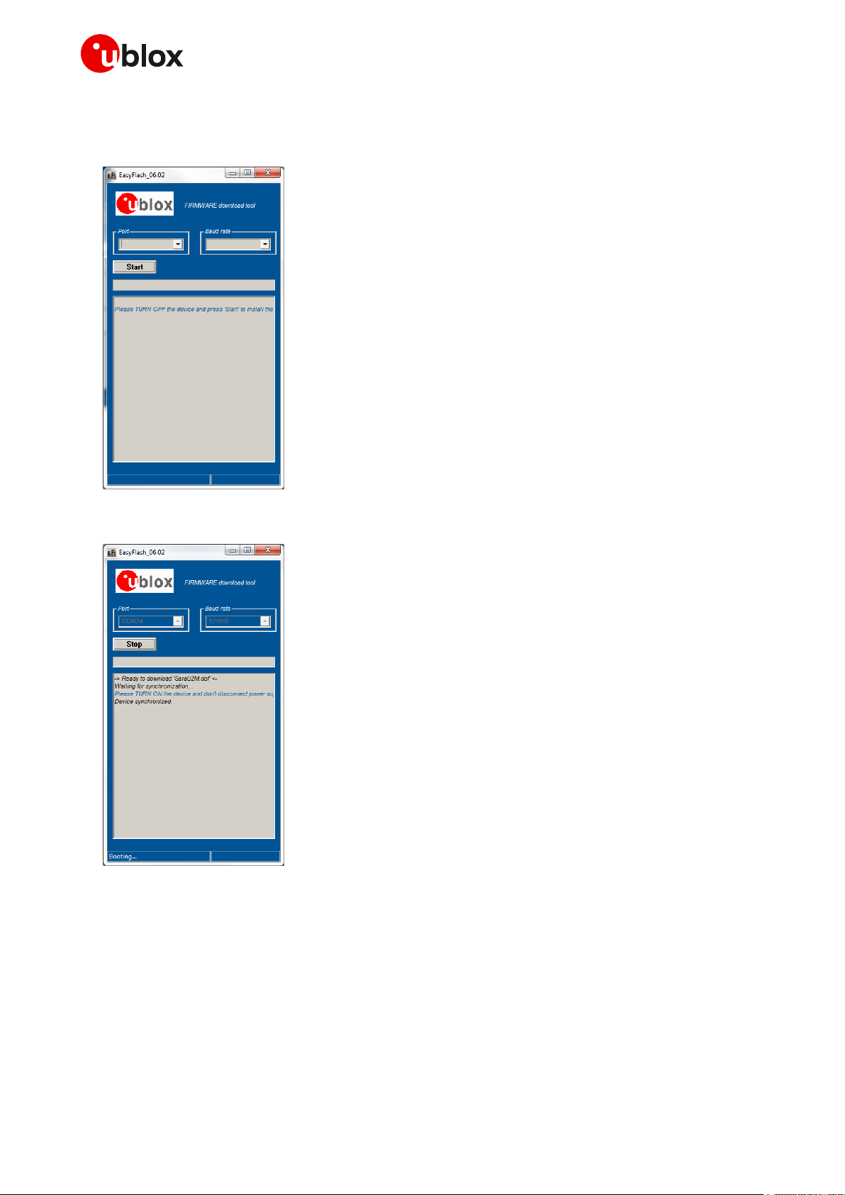
3. Run the EasyFlash tool.
Do not use EasyFlash_06.02.00 and previous versions for the FW update on TOBY-L4 series
UBX-13001845 - R18 EasyFlash Page 8 of 43
Page 9
Cellular module firmware update - Application note
4. Select the COM port where the module is connected and the baud rate (921’600 bit/s is suggested
if supported by the used external parts).
5. Click the EasyFlash “Start” button.
6. Keep the module RESET_N input low for a proper time period when performing a module reset.
UBX-13001845 - R18 EasyFlash Page 9 of 43
Page 10
Cellular module firmware update - Application note
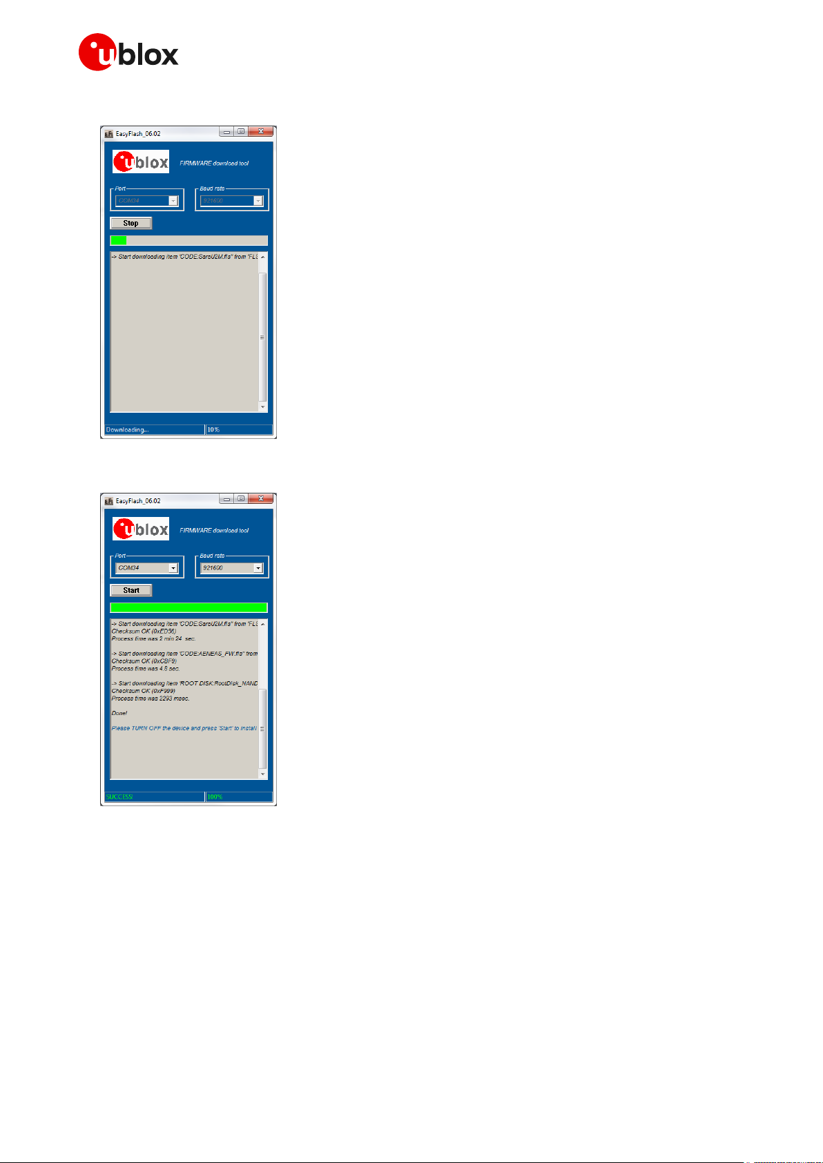
7. The download starts.
8. The firmware update is completed!
9. Close EasyFlash tool and reset the module.
UBX-13001845 - R18 EasyFlash Page 10 of 43
Page 11
Cellular module firmware update - Application note
3.2 FW download over USB
☞ This section does not apply to TOBY-L2 / MPCI-L2 / LEON-G1 / SARA-G3 series modules.
The firmware download using EasyFlash tool over the USB interface is similar to that for UART or
UART AUX, following these steps:
☞ Install the FlashUSB drivers before flashing over the USB interface. If the drivers are not installed,
the download does not start.
1. Power on the module.
2. Connect the PC or the notebook to the USB interface of the module.
☞ See the corresponding EVK user guide for the correct jumpers and slides configuration for the FW
update.
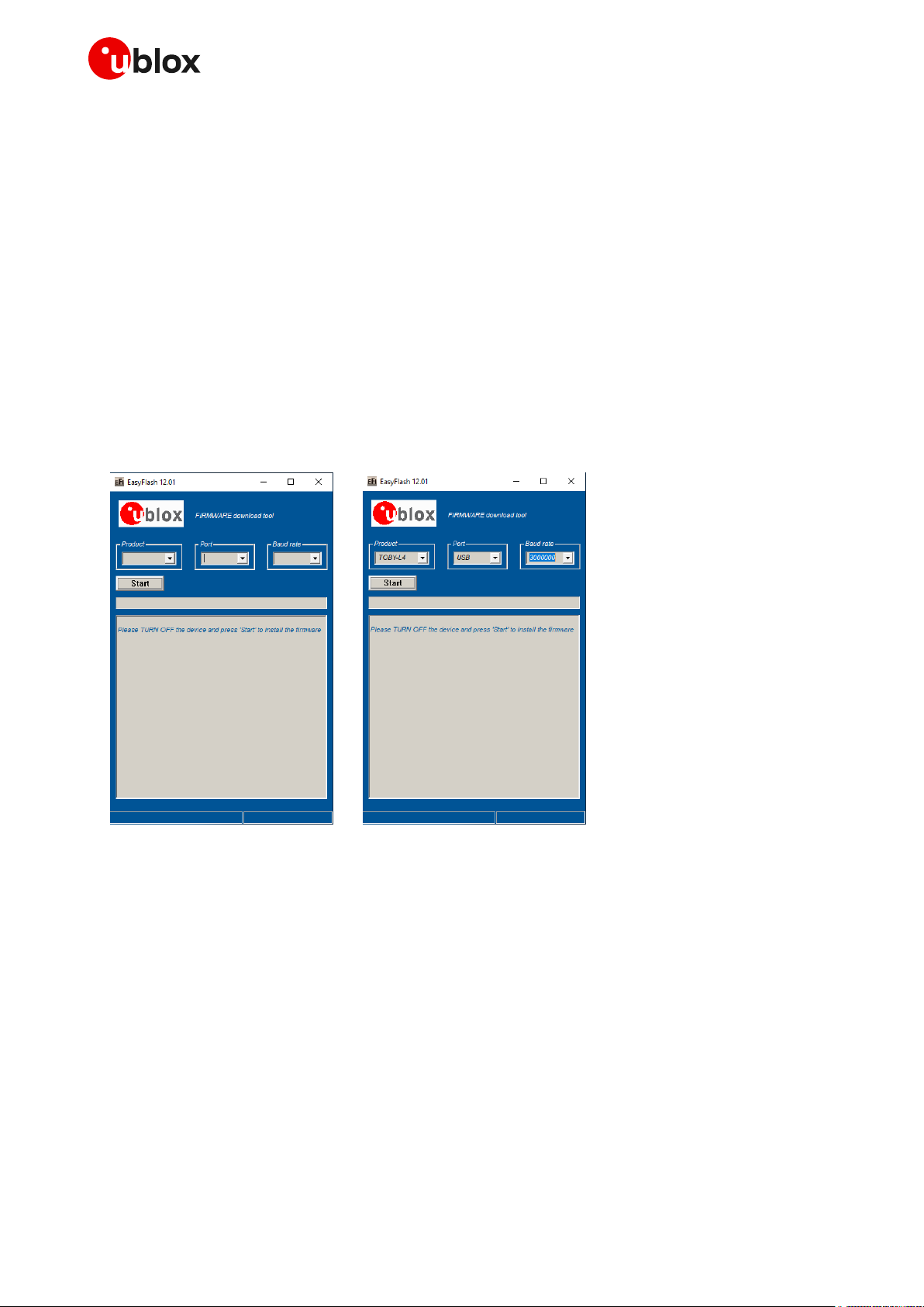
3. Run the EasyFlash tool.
4. Select the interested module series clicking on "Product" combo box and select the interface by
means of the “Port” combo box (the COM port and baud rate are not applicable when using USB).
UBX-13001845 - R18 EasyFlash Page 11 of 43
Page 12
Cellular module firmware update - Application note
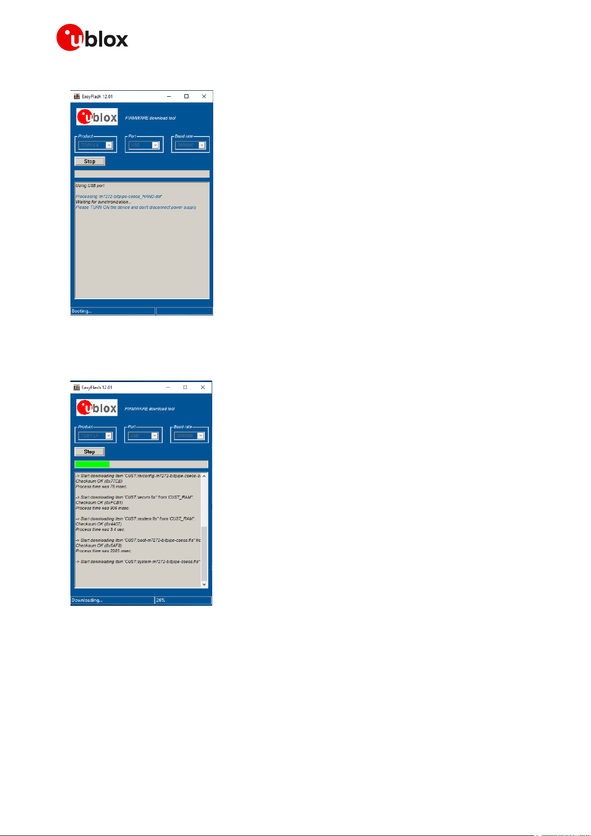
5. Click the EasyFlash “Start” button.
6. Keep the module RESET_N input low for a proper time period when performing a module reset.
7. The download starts.
UBX-13001845 - R18 EasyFlash Page 12 of 43
Page 13
Cellular module firmware update - Application note
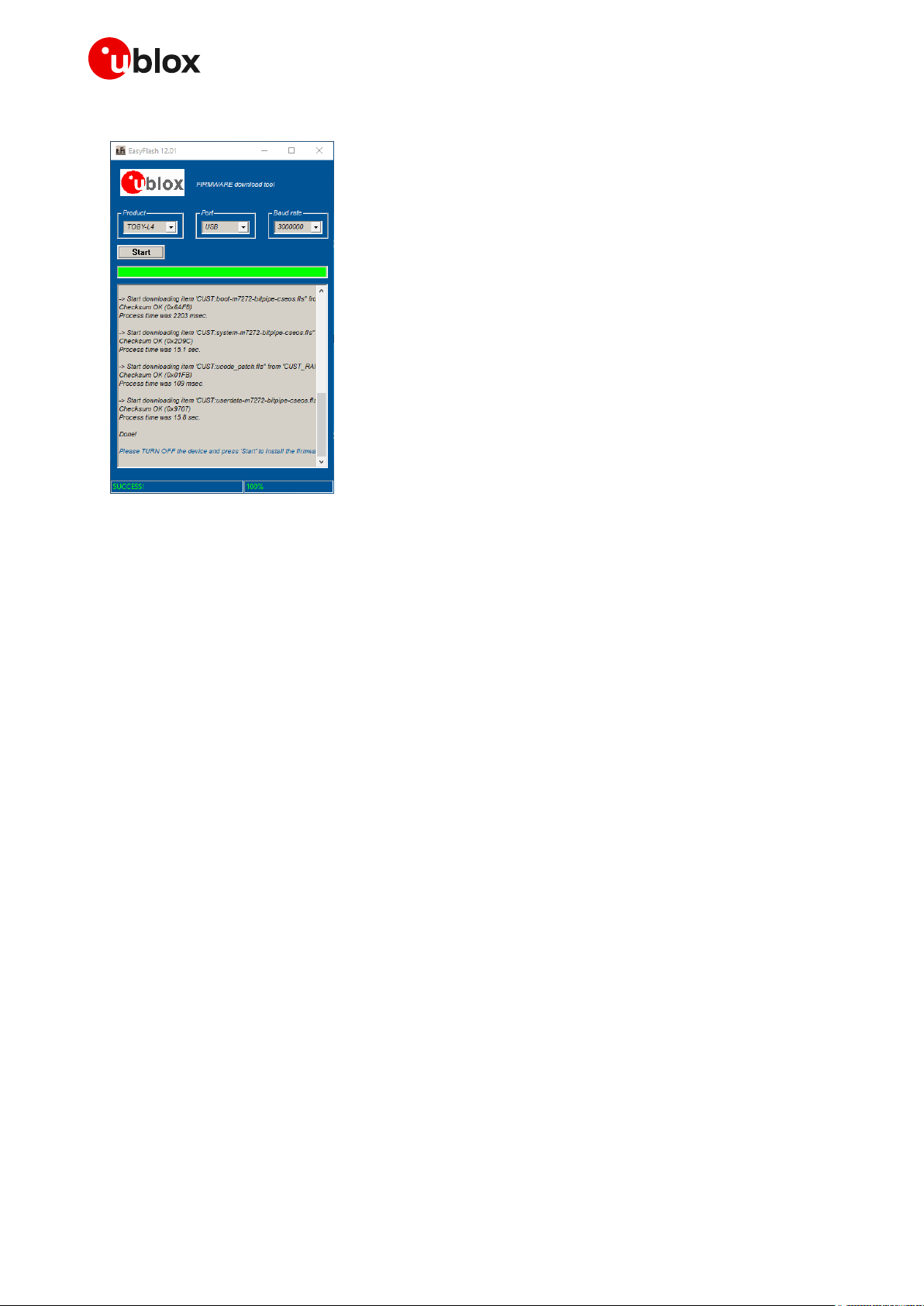
8. The firmware update is completed!
9. Close the EasyFlash tool and reset the module to start.
UBX-13001845 - R18 EasyFlash Page 13 of 43
Page 14

Cellular module firmware update - Application note
3.3 FW download over USB (TOBY-L2, MPCI-L2 series only)
The firmware download using EasyFlash tool over the USB interface is similar to that for UART or
UART AUX.
☞ Install the TOBY-L2 USB drivers before flashing over the USB interface. If the drivers are not
installed, the download does not start.
To download the firmware with EasyFlash, follow these steps:
1. Power on the module.
2. Connect the PC or the notebook to the module USB interface.
3. Run the EasyFlash tool.
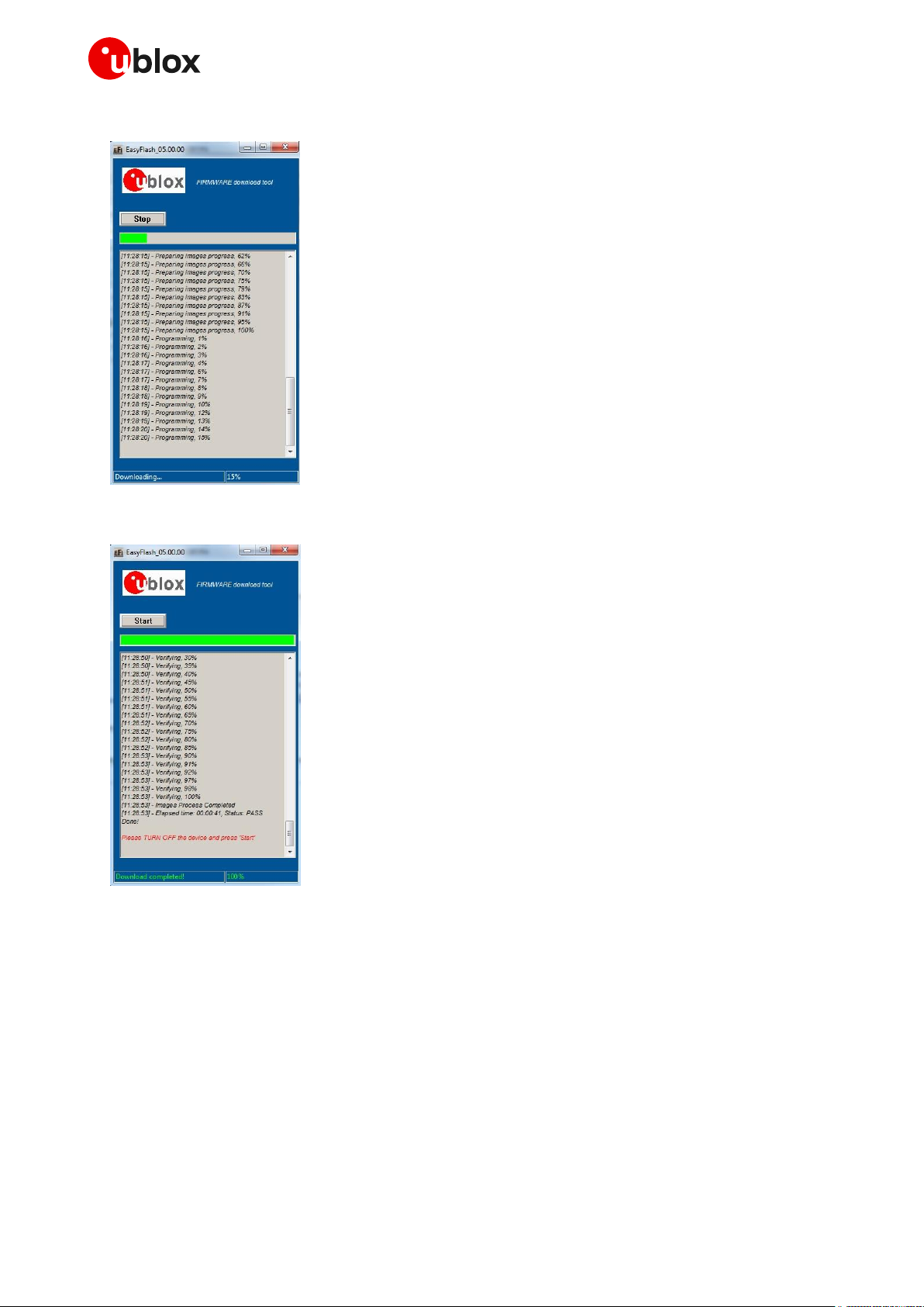
4. Click the EasyFlash “Start” button and wait for packet decompression (yellow progress bar).
5. Keep the module RESET_N input low for a proper time period when performing a module reset.
UBX-13001845 - R18 EasyFlash Page 14 of 43
Page 15
Cellular module firmware update - Application note
6. The download starts.
7. The firmware update is completed!
8. Close the EasyFlash tool and reset the module to start.
UBX-13001845 - R18 EasyFlash Page 15 of 43
Page 16

Cellular module firmware update - Application note
Type
Syntax
Response
Example
Set
AT+UFWUPD=<md5>
+UFWUPD: ONGOING
CCC…
OK
UFWUPD REBOOT
AT+UFWUPD=a07a5534201b2e42dd2d
964920e57319
+UFWUPD: ONGOING
CCC…
OK
UFWUPD REBOOT
Parameter
Type
Description
<md5>
Number
32 hex number
4 Firmware update Over AT commands (FOAT)
☞ See Table 1 for the list of modules and interfaces supporting FOAT.
The firmware update can be carried out via the AT interface of the module (see the table reported in
section 1) through the +UFWUPD AT command and Xmodem (or Xmodem-1k protocol) protocol. After
having downloaded the “FOAT update” file delivered by u-blox, the Xmodem protocol will update the
module.
☞ The Xmodem protocol handles the errors (data corruption, data loss etc.) internally during the
update phase.
☞ When a firmware update is triggered, the host processor can choose either the Xmodem-1k
protocol (1024 byte packets) or Xmodem protocol (128 byte packets).
The command syntax differs depending on the module series. See the corresponding section for the
detailed description.
4.1 TOBY-L2, MPCI-L2 series AT command syntax
On TOBY-L2 / MPCI-L2 series, the FW update over AT commands is performed by means of a BIN file
officially released by u-blox. To start the process, the proper MD5 signature is needed.
☞ Use the proper released file (*.bin) for Xmodem (128) and Xmodem-1k (1024) and use as <md5>
value the MD5 signature of the file (*.zip) used with +UFWINSTALL AT command.
4.1.1 Defined values
☞ The <md5> parameter is not mandatory for TOBY-L2/ MPCI-L2 "00", "50", "60" product versions.
The AT command can be issued over the USB or the UART (if supported) interface of the module.
On receiving the AT+UFWUPD command, the module:
Starts the Xmodem protocol and waits for data on the channel where the command has been sent.
Sends the waiting characters to the host terminal via the AT interface: up to ten “C” (0x43)
characters and up to ten <NACK> (0x15) characters. Each character is sent with a 10 second
timeout after the last one. The total timeout is 200 s. This is the time during which the host
terminal must send TX data.
☞ If the data is sent while the “C” character is coming, the protocol uses the CRC method to detect
transmission errors, otherwise the standard CHECKSUM method is used.
Then it is possible to download the new module image via the Xmodem protocol using a standard
terminal program with HW flow control (e.g. with a PC environment HyperTerminal with these
UBX-13001845 - R18 Firmware update Over AT commands (FOAT) Page 16 of 43
Page 17

Cellular module firmware update - Application note
settings: frame format 8N1, HW flow control active, baud rate configurable, power saving disabled).
Intra-character timeout is 1 second, (after receiving first valid data from the host).
The maximum number of allowed errors (timeout, bad data) is 10, after that Xmodem exit with this
string:
ERROR1
☞ On TOBY-L2 “00”, “01”, “50” and “60” product versions and MPCI-L2 “00” and “60” product
versions if 10 errors are provided, the Xmodem exits with these strings:
"too many errors; giving up"
ERROR1
Once the update file has been downloaded, if the <md5> parameter is provided correctly (32 hex
digits), then the MD5 check is performed.
If the <md5>parameter is provided incorrectly (less digits, more digits, or at least one non-hex digit),
then the download will not be started, the module will exit from Firmware Update Mode, and the
current firmware will be started. A proper error result code will be issued on the same channel where
the command has been sent.
When a firmware update is triggered, the host processor can choose either the Xmodem-1k protocol
(1024 byte packets) or Xmodem protocol (128 byte packets).
The module sends an <EOT> character (0x04) via the terminal for notifying the end of the download.
At the end of the download procedure, the module reboots and starts the update process, which
will take about 1 minute. No messages are issued on the terminal during this phase.
When the module reboots, the USB will be detached, and attached again at the next boot in
Firmware Update Mode (with the same USB CDC–ACM enumeration of operative mode). The USB
port will be ready within 60 seconds after reboot. The user must connect again with the USB
CDC-ACM port.
At the end of the update process the module reboots again with the new firmware installed and
the NVM and profile parameters set to factory-programmed values.
☞ The Xmodem protocol handles the errors (data corruption, data loss etc.) internally during the
update phase.
☞ In case of power loss during the update phase, at the next module wake-up a fault is detected and
the module remains in Firmware Update Mode expecting the upload to restart from Xmodem
handshake.
☞ If the FW download ends with an ERROR1 condition, the module exits from Firmware Update Mode
and returns to normal mode since the FW is still unchanged and usable (FW not corrupted by
previous download process)
☞ If the module does not receive any data from the host terminal after the tenth <NACK>, then the
module will exit from Firmware Update Mode and return to normal mode. Since the FW is
unchanged and still usable, ERROR1 is issued from the module to indicate: FW not corrupted by
previous update process.
On the USB interface this performance is provided:
Speed: ~500 kB/s
Time to download update.zip: ~6 minutes
Time to perform the update: ~1 minute
UBX-13001845 - R18 Firmware update Over AT commands (FOAT) Page 17 of 43
Page 18

Cellular module firmware update - Application note
Response
Description
ERROR1
too many errors; giving up
General error. The operation has been interrupted before starting to write
in flash, the current FW is unchanged; the module exits Firmware Update
Mode and starts the current FW
bad block ones compl
Block number error
unexpected block no, #num, expecting #num1
Unexpected block number
crc error, expected num, got num1
CRC error
checksum error, expected num, got num1
Checksum error
md5 not matching, update failed
ERROR1
Download has been done correctly but the MD5 calculated from the
downloaded file does not match the one provided in the command.
The module exits Firmware Update Mode and starts the current FW.
short md5, update failed
ERROR1
md5 provided in the command is shorter than expected.
Download is not started. The module exits Firmware Update Mode and
starts the current FW.
long md5, update failed
ERROR1
md5 provided in the command is longer than expected.
Download is not started. The module exits Firmware Update Mode and
starts the current FW.
md5 with no hex digits, update failed
ERROR1
md5 provided in the command has at least one non-hex digit.
Download is not started. The module exits Firmware Update Mode and
starts the current FW.
missing md5, update failed
ERROR1
md5 ins missing from provided AT command. The update is not started.
The module exits Firmware Update Mode and starts the actual FW.
4.1.2 Error result codes
4.2 LEON-G1, SARA-G3, LISA-U2, SARA-U2, TOBY-R2,
LARA-R2 series AT command syntax
Depending on the firmware update type to perform, a file in .FLS or in .DFFS format is needed.
The file in .FLS format includes all the needed parts for the FW, NVM and profile update
The file in .DFFS format includes all the needed parts for the File System update
☞ LEON-G1, SARA-G3, SARA-U2 (except for SARA-U201) and LISA-U2 series (except for
LISA-U2x0-x1S and previous versions) allow updating the File System using only the file in DFFS
format.
☞ It is not possible to update the firmware using a peripheral where the multiplexer is enabled.
On receiving the +UFWUPD AT command, the module:
Resets, restarts and switches to Firmware Update Mode
Configures the serial port at the new baud rate (if any)
In case of FOAT over USB, the module will be detached after sending the command (because of
the reset), and attached again at the next boot in Firmware Update Mode (with the same USB
CDC–ACM enumeration of operative mode). USB port will be ready within 5 s after the command
issued. The user must connect again with the USB CDC–ACM port.
Sends the IRC +UFWUPD: ONGOING command to the host terminal via the AT interface, followed
by up to three “C” (0x43) characters and up to ten <NACK> (0x15) characters. The first three “C”
characters are sent with a 3 second timeout after the last one, next <NACK> characters are sent
with a 10 s timeout after the last one. The total timeout is 109 seconds. This is the timeout within
which the host terminal must send TX data
UBX-13001845 - R18 Firmware update Over AT commands (FOAT) Page 18 of 43
Page 19

Cellular module firmware update - Application note
DTE
Cellular module
Description
AT+UFWUPD=0,460800
+UFWUPD: ONGOING
Cellular module response sent at
460’800 bit/s
CCC<NACK><NACK><NACK><NACK><NACK><
NACK><NACK><NACK><NACK><NACK>
Sent at 460’800 bit/s: up to 10 <NACK>s
Code image using Xmodem-1k protocol
sent (at 460’800 bit/s) to the u-blox
cellular module
OK
Cellular module response sent at
460’800 bit/s: the download is complete
and the reboot follows.
The module is updated to the new FW
versions and it is ready to receive further
commands.
☞ If data is sent while the “C” character is coming, the protocol uses the CRC method to detect
transmission errors, otherwise the standard CHECKSUM method is used.
Then it is possible to download the new module image via the Xmodem protocol using a standard
terminal program at the selected baud rate without flow control (e.g. HyperTerminal with these
settings: frame format 8N1, no flow control, baud rate configurable, power saving disabled). At the
end of the procedure, the final response is sent at the baud rate set for the FW update. When the
FOAT procedure is completed, the baud rate is set to the current loaded profile of the new FW version.
☞ Both IRC and any further final responses are sent at the new baud rate. Only a syntax error in the
AT+UFWUPD command triggers an error result code at the original baud rate.
☞ LEON-G1 series requires Xmodem packets to be sent within 50 ms.
☞ SARA-G3 series requires Xmodem packets to be sent within 100 ms.
☞ LISA-U2 and SARA-U2 series require flow control active on the UART interface. If the flow control
is disabled, the RTS line must be held to the ON state.
Table 4 provides an example of the Firmware update Over AT commands procedure.
Table 4: Firmware Over AT commands procedure
UBX-13001845 - R18 Firmware update Over AT commands (FOAT) Page 19 of 43
Page 20

Cellular module firmware update - Application note
☞ LEON-G1 series modules send a <CAN> character (0x18) after 8 MB of data instead of waiting for
the <EOT> character (0x04) from the sender. The <CAN> character can be interpreted as an
ABORT from the module side.
☞ LISA-U2 / SARA-U2 and SARA-G3 series modules send an <EOT> character (0x04) via the terminal
for notifying the end of the download.
☞ On LISA-U2 / SARA-U2 series, the <CAN> response is issued if it reaches the timeout after
receiving the first character. Issue a new AT+UFWUPD command for a new FOAT session.
☞ In case of power loss during the update, at the next module wake-up a fault is detected and the
module remains in Firmware Update Mode, expecting the upload to restart from an Xmodem
handshake.
☞ If the FW download ends with an ERROR condition, the module remains in Firmware Update Mode,
expecting the upload to restart from Xmodem handshake (all ERROR condition except ERROR1,
described in section 4.2.2).
☞ If the module does not receive any data from the host terminal after ten <NACK>s, then the
module will exit from Firmware Update Mode and return to normal mode. Since the FW is
unchanged and still usable, ERROR1 is issued from the module to indicate: FW not corrupted by
previous update process.
☞ If <filetype> is set to 2, make sure the file contains both the firmware and File System images.
UBX-13001845 - R18 Firmware update Over AT commands (FOAT) Page 20 of 43
Page 21

Cellular module firmware update - Application note
Type
Syntax
Response
Example
Set
AT+UFWUPD=<filetype>[,<speed>]
+UFWUPD: ONGOING
(sent at new baud rate, if
specified)
AT+UFWUPD=0
+UFWUPD: ONGOING
Test
AT+UFWUPD=?
+UFWUPD: (list of supported
<filetype>s),(list of
supported <speed>s)
OK
+UFWUPD: (0-2),(57600,115200,2
30400,460800,921600)
OK
IRC
+UFWUPD: ONGOING
Parameter
Type
Description
<filetype>
Number
Download type
0: firmware image update
1: file system image update
2: firmware and file system image update
<speed>
Number
Baud rate in b/s
115’200 (default value)
230’400
460’800
921’600
3’000’000
3’250’000
6’000’000
6’500’000
LEON-G1
LISA-U2
SARA-G3
SARA-U2
TOBY-R2
LARA-R2
Table 5: AT+UFWUPD command syntax
4.2.1 Defined values
Table 6: AT+UFWUPD parameter description
☞ <filetype>=1 is not supported by SARA-G300 / SARA-G310 modules.
☞ <filetype>=2 is supported only by LISA-U2 “00”, “01” and SARA-U201 product versions.
☞ <speed>=3’000’000, 3’250’000, 6’000’000, 6’500’000 are not supported by LEON-G1 / SARA-G3 /
LISA-U2 / SARA-U2 series modules.
☞ On SARA-U2 "04" product version the FW update process is not allowed on the AUX UART
interface.
4.2.2 Error result codes
These icons indicate the products to which the error result codes apply:
: LEON-G1 series
: LISA-U2 series
: SARA-G3 series
: SARA-U2 series
: TOBY-R2 series
: LARA-R2 series
UBX-13001845 - R18 Firmware update Over AT commands (FOAT) Page 21 of 43
Page 22

Cellular module firmware update - Application note
Response
Product
Description
ERROR1
The operation has been interrupted before starting to
write in flash. The current FW is unchanged and the
module exits Firmware Update Mode and starts the
current FW.
ERROR2
The operation has been interrupted during FW updating
(after starting to write in flash). The current firmware is
corrupted and the module remains in Firmware Update
Mode.
ERROR3
The signature check fails.
ERROR4
The module has received an unexpected EOT because
not all the expected bytes have been received.
ERROR5
The boot does not support the selected baud rate.
ERROR6
Invalid AT command sent during boot.
FLS header decoding
failed
An error occurs during decoding of file header.
Buffer Data Overrun
Data is sent too slowly.
Timeout
No data is coming. The +UFWUPD command must be resent (if the image has not been corrupted by previous
update procedures, otherwise update autonomously
restarts).
DTE
Cellular module
Description
AT+UFWUPD=0
+UFWUPD: ONGOING
Firmware image update
AT+UFWUPD=1
+UFWUPD: ONGOING
Flash File System image update
After the firmware image update, the
module boots and it will be available to the
user after the time needed for the file
system formatting (maximum 2 minutes).
DTE
Cellular module
Description
AT+UFWUPD=2
+UFWUPD: ONGOING
Firmware and Flash File System image
update
LARA-R2
TOBY-R2
SARA-U2
SARA-G3
LISA-U2
LEON-G1
LARA-R2
TOBY-R2
SARA-U2
SARA-G3
LISA-U2
LEON-G1
LEON-G1
SARA-G3
LEON-G1
LEON-G1
LEON-G1
LARA-R2
TOBY-R2
SARA-U2
SARA-G3
LISA-U2
LEON-G1
SARA-G3
LEON-G1
LARA-R2
TOBY-R2
SARA-U2
SARA-G3
LISA-U2
LEON-G1
Table 7: AT+UFWUPD error codes
☞ ERROR2 is not sent in LISA-U2 / SARA-U2 when an EOT has interrupted the firmware update
process.
4.2.3 FW update procedure on LISA-U2 series
On LISA-U2 "01" product versions it is not possible to use <filetype>=2 to simultaneously download
both the firmware image and the flash file system. Follow this procedure to update the firmware
version from LISA-U2 "01" product versions to LISA-U2 "x2" product versions:
Follow this procedure to revert the firmware version from LISA-U2x0-x2S to LISA-U2x0-x1S:
UBX-13001845 - R18 Firmware update Over AT commands (FOAT) Page 22 of 43
Page 23

Cellular module firmware update - Application note
Type
Syntax
Response
Example
Set
AT+UFWINSTALL=<filename>[,<Ser
ial_Port_Number>[,<BaudRate>]]
OK
AT+UFWINSTALL="update.upd",1,1
15200
OK
Test
AT+UFWINSTALL=?
+UFWINSTALL: "filename",(list
of supported
<Serial_Port_Number>s),(list
of supported <BaudRate>s)
OK
+UFWINSTALL: "filename",(0,1,4
-
6),(19200,38400,57600,115200,2
30400,460800,921600)
OK
URC
+UUFWINSTALL: <progress
install>
5 Firmware install (+UFWINSTALL)
5.1 Introduction
☞ See Table 1 for the list of modules and interfaces supporting the firmware install feature.
The firmware installation procedure triggers the firmware update installation via AT command,
starting from an update file stored in module file system.
The +UFWINSTALL command handles the firmware installation procedure. This command could be
used as the final part of implementation of a FW update procedure after having stored the FW update
package in the module file system.
The update file must be stored in the module file system before starting the firmware update
installation procedure. Otherwise an error result code is issued. The procedure to store the update file
in the module file system is up to the user via OTA/FTP/HTTP, or using the +UDWNFILE AT command.
The firmware update can be triggered using the following interfaces:
UART with configurable baud rate (only one port is available)
USB with configurable USB instance
The “OK” final result code notifies that the module correctly received the FW update request and the
update process will start immediately thereafter.
During the update process, the module cannot be used to make calls, even emergency calls. The
update process is fault tolerant, even if the battery is suddenly removed.
At the end of a successful installation, the module boots up, NVM and profiles data are set to the
factory-programmed values of the new firmware version, and the SIM is reset (the PIN will be required
if enabled). See the u-blox AT commands manual [1] for the factory-programmed values.
⚠ Do not remove the power supply or reset the module during the installation procedure even if it is
fault tolerant! The module will reboot automatically after the end of update procedure.
5.2 LISA-U2, SARA-U2, LARA-R2, TOBY-R2 AT command syntax
UBX-13001845 - R18 Firmware install (+UFWINSTALL) Page 23 of 43
Page 24

Cellular module firmware update - Application note
Parameter
Type
Description
<filename>
String
Update file previously downloaded in module file system. The update file
can have different extension.
<Serial_Port_Number>
Number
Serial interface where the progress percentage and information text
responses will be sent:
0: no info will be shown
1: UART interface
4: USB1
5: USB2
6: USB3
If omitted, the command will take as default value for
<Serial_Port_Number> the port where the command is issued.
<BaudRate>
Number
Available baud rates in b/s:
19’200
38’400
57’600
115’200
230’400
460’800
921’600
3’000’000
3’250’000
6’000’000
6’500’000
When a USB interface is selected, the parameter has no effect in the FW
install configuration.
If omitted, the command will take as default value for the parameter the
baud rate of the port where the command is issued.
<progress_install>
Integer
Provides the installation progress from 0 to 100 and update result (see
section B).
5.2.1 Defined values
☞ <speed>=3’000’000, 3’250’000, 6’000’000, 6’500’000 are not supported by LISA-U2 / SARA-U2
series modules.
☞ Store the update file into the module file system before starting the install with +UFWINSTALL.
Otherwise the “FFS file not found” error result code is issued. The procedure for FS storing is up
to the user (via +UFTPC, or +UDWNFILE). When the new FW has been installed, the user can
optionally delete the “filename” using the file system AT commands (for more details, see the
u-blox AT command manual [1] +UDELFILE).
During the update operations, the +UUFWINSTALL URC displays the progress indication and the
result operation on the interface chosen via the +UFWINSTALL command. When the FW update is
completed, a URC will notify the final result of the operation. The last URC with a value greater than
100 indicates the update operation result (e.g. 128 means operation completed with success). For
more details, see section B.
☞ The progression of the installation is incremental, but the URC step can be different from 1.
UBX-13001845 - R18 Firmware install (+UFWINSTALL) Page 24 of 43
Page 25

Cellular module firmware update - Application note
Command
Response
AT+UDWNFILE="Update_FW_90_to_91.upd",867263
OK
AT+UFWINSTALL="Update_FW_90_to_91.upd",1,115200
OK +UUFWINSTALL: 1
+UUFWINSTALL: 2
+UUFWINSTALL: 3
+UUFWINSTALL: 4
…
+UUFWINSTALL: 99
+UUFWINSTALL: 100
+UUFWINSTALL: 128
AT+UDELFILE="Update_FW_90_to_91.upd"
OK
Command
Response
AT+UFTPC=4,"Update_FW_90_to_91.upd","Update_FW_90_
to_91.upd"
OK
AT+UFWINSTALL="Update_FW_90_to_91.upd",1,115200
OK +UUFWINSTALL: 1
+UUFWINSTALL: 2
+UUFWINSTALL: 3
+UUFWINSTALL: 4
…
+UUFWINSTALL: 99
+UUFWINSTALL: 100
+UUFWINSTALL: 128
AT+UDELFILE="Update_FW_90_to_91.upd"
OK
Type
Syntax
Response
Example
Set
AT+UFWINSTALL=<md5>
OK
UFWINSTALL REBOOT
AT+UFWINSTALL=a07a553420
1b2e42dd2d964920e57319
OK
UFWINSTALL REBOOT
Test
AT+UFWINSTALL=?
OK
Parameter
Type
Description
<md5>
Number
32 hexadecimal number
Example with +UDWNFILE:
Example with +UFTPC:
Prerequisite: an FTP connection is already established (see the AT commands examples application
note [2] for more details.
5.3 TOBY-L2, MPCI-L2 AT command syntax
5.3.1 Defined values
After the command is issued, the module reboots and starts the installation process, which will take
about 1 minute. No result codes are issued on the terminal during this phase. At the end of the update
UBX-13001845 - R18 Firmware install (+UFWINSTALL) Page 25 of 43
Page 26
Cellular module firmware update - Application note
Command
Response
AT+UDWNFILE="update.zip",23245004
OK
AT+UFWINSTALL=3ab67be42a797549699bf2f22f84860d
OK
UFWINSTALL REBOOT
Command
Response
AT+UFTPC=100,"Update.zip"
OK
+UUFTPCR: 100,1,a07a5534201b2e42dd2d964920e57319
AT+UFWINSTALL=a07a5534201b2e42dd2d964920e57319
OK
UFWINSTALL REBOOT
Command
Response
AT+UHTTPC=1,100,"/update_L210_FWI.zip"
OK
+UUHTTPCR: 1,100,1,200,"a57c33e66457a89ad0abb7c2d9
aa7938"
AT+UFWINSTALL=a57c33e66457a89ad0abb7c2d9aa7938
OK
UFWINSTALL REBOOT
5
process, the module reboots again with the new firmware installed, NVM parameters and the file
system restored to the factory-programmed values.
If the <md5> parameter is correctly provided (32 hex digits), then a check is done with the update file
stored in the module.
If the <md5> parameter is provided incorrectly (less digits, more digits, or at least one non-hex digit),
then the install process will not be started, the module will exit from Firmware Install Mode, and the
current firmware will continue to run. An appropriate error result code will be issued on the same
interface where the command has been sent.
In case of power loss during the installation phase, at the next module wake-up a fault is detected and
the module remains in Firmware Install Mode until the end of the procedure (installation terminated).
Store the update file into the module cache folder before starting the install with +UFWINSTALL.
Otherwise the “update file not found” error result code is issued. The procedure for storing is up to the
user by means of +UDWNFILE, +UFTPC or +UHTTPC AT commands. These commands erase the
cache content before storing the new update file.
Example with +UDWNFILE:
Prerequisite: the name of the file must be “update.zip” (for more details, see the AT commands
manual [2]).
Example with +UFTPC:
Prerequisite: an FTP connection is already established (for more details, see the AT commands
examples application note [2]).
Example with +UHTTPC5:
Prerequisite: Configure an HTTP application profile to ensure access to the HTTP or HTTPS server
(see the AT commands examples application note [2] for more details).
The example does not apply to TOBY-L200 / TOBY-L210 / TOBY-L220 / TOBY-L280 / MPCI-L200 / MPCI-L210 / MPCI-L220 /
MPCI-L280 "00", "01", "02", "62", "72" and TOBY-L201 / MPCI-L201 "01" product versions, TOBY-L201-01S TOBY-L200-03S-00,
TOBY-L201-02S-00, TOBY-L210-03A-00, TOBY-L210-03S-00, TOBY-L280-03S-00 and MPCI-L201-02S-00.
UBX-13001845 - R18 Firmware install (+UFWINSTALL) Page 26 of 43
Page 27
Cellular module firmware update - Application note
Type
Syntax
Response
Example
Set
AT+UFWINSTALL
OK
AT+UFWINSTALL
OK
+UUFWINSTALL: REBOOT
AT: READY
+UUFWINSTALL: 128
Test
AT+UFWINSTALL=?
OK
URC
+UUFWINSTALL: <status_install>
Parameter
Type
Description
<status_install>
Number/String
Provides the installation start message (“REBOOT” string) and the update
result code (see the section B)
5.4 TOBY-L4 AT command syntax
5.4.1 Defined values
Store the update file into the module before starting the FW installation with the +UFWINSTALL AT
command. The procedure for storing is up to the user by means of the +UDWNFILE AT command.
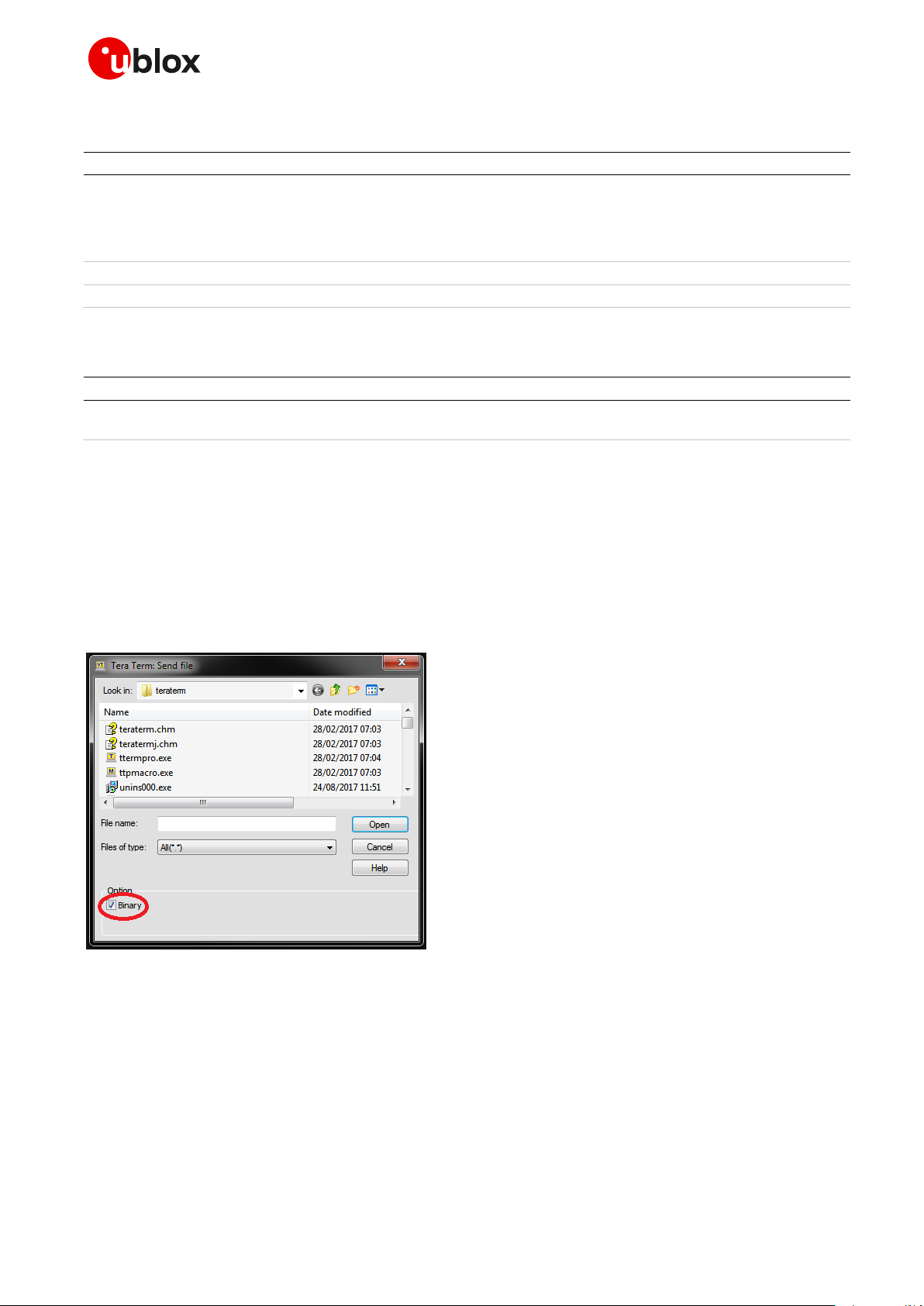
TOBY-L4 modules have a dedicated communications port (referenced as “EXT”) for dealing with user-
provided files. The +UDWNFILE and +UDELFILE AT commands support the “FOTA_EXT” tag to
distinguish the update package sent to this dedicated port. Send in binary mode the files to this port
(i.e. not using Xmodem or other similar protocols). To achieve this, properly configure the flags or
settings of the serial communication tools (e.g. Teraterm for Windows) in order to send files using
only “raw binary” mode (see Figure 1, for example):
Figure 1: Teraterm send file dialog example
In a Linux environment, after issuing the AT+UDWNFILE command, it is possible to send binary files
to a serial device using these commands, assuming that “/dev/ttyACM3” is the EXT serial port and
“ota−update.zip” is the update package file:
stty –F /dev/ttyACM3 raw -echo (to set the port in raw non echo mode)
cat ota-update.zip > /dev/ttyACM3 (to download the firmware to the module)
☞ Remove a possible update file, due to a previously failed firmware install procedure, using the
+UDELFILE AT command, before sending a new update file. Since the +UDWNFILE AT command
supports also sending an update file in blocks, it is highly recommended to do this. If there are no
UBX-13001845 - R18 Firmware install (+UFWINSTALL) Page 27 of 43
Page 28

Cellular module firmware update - Application note
Command
Response (AT interface)
Response (EXT port)
AT+UDELFILE="","FOTA_EXT"
OK
AT+UDWNFILE="",20000000,"FOTA_EXT"
> <send first chunk of 20000000 bytes to EXT PORT>
OK AT+UDWNFILE="",20000000,"FOTA_EXT"
> <send second chunk of 20000000 bytes to EXT PORT>
OK AT+UDWNFILE="",3442631,"FOTA_EXT"
> <send last chunk of 3442631 bytes to EXT PORT>
OK AT+UFWINSTALL
OK
+UUFWINSTALL: REBOOT
AT: READY
+UUFWINSTALL: 128
update files stored, the +UDELFILE returns an error result code. After a correct completion of a
firmware update procedure, the update file is automatically deleted.
After the command is issued, the module reboots and starts the FW installation process which will
take up to 3-4 minutes long. During the update process, the module reboots multiple times. No
intermediate result codes are issued on the terminal during this phase. The update package file is
stored in a dedicated area of the module flash, so the update process can also be delayed and
triggered after a reboot.
The +UFWINSTALL AT command checks only for the presence of the update file. Consistency checks
are done during the update procedure. If the checks fail, the update file is left in the module file system
and a proper URC with the error result code is issued after the final reboot (see section B). In case of a
power loss during the installation phase, at the next module boot a fault is detected and the module
remains in Firmware Install Mode until the end of the procedure (installation terminated).
At the end of the FW update process, the module reboots again with the new firmware installed; NVM,
profiles and the file system are restored to the factory-programmed values. The final
+UUFWINSTALL URC shows the firmware update result code (error or success).
Example with +UDWNFILE: update file is 43’442’631 bytes and split in chunks of 20’000’000 bytes
5.5 Firmware Install specifications
5.5.1 Generation of the “update file”
The “Update file” contains the binary differences between the source and target firmware region
which is updatable, e.g. all the constant sources.
The update file contains the binary data to allow the user to update the FW module.
u-blox delivers the “update file” for customers.
☞ On the TOBY-L4 series, the update file always contains a complete update to the target version.
UBX-13001845 - R18 Firmware install (+UFWINSTALL) Page 28 of 43
Page 29

Cellular module firmware update - Application note
5.5.2 Recovery mechanism
In case of a firmware update failure (for instance possibly due to power loss or cable detach), the FW
installation procedure starts again. In the event of a FW install failure but where the update process
has still not written anything in the flash memory, the update procedure stops and runs the old
firmware.
☞ If the power is removed before 35 s the AT+UFWINSTALL command must be re-issued.
5.5.3 Installation performance
The installation time depends on the update file size and the section changed in the SW memory map
between two SW versions.
The time to update the firmware can vary and in the worst case is less than 10 minutes.
5.5.4 Limitations
Update procedure cannot update the module file system. All the user settings (NVM, profiles) are
restored to the factory-programmed values. Calibration data are retained.
☞ The file system is restored to the factory-programmed value (see Table 3).
UBX-13001845 - R18 Firmware install (+UFWINSTALL) Page 29 of 43
Page 30

Cellular module firmware update - Application note
Abbreviation
Definition
API
Application Programming Interface
AT
AT Command Interpreter Software Subsystem, or attention
CRC
Cyclic Redundancy Check
DOF
Download One File
DTE
Data Terminal Equipment
EOT
End of Transmission
FFS
Flash File System
FOAT
Firmware Over AT commands
FOTA
Firmware Over The Air
FTP
File Transfer Protocol
FW
Firmware
IMEI
International Mobile Equipment Identity
IP
Internet Protocol
IRC
Intermediate Result Code
NVM
Non Volatile Memory
ODIS
OMA-DM IMEI Sync
OMA-DM
Open Mobile Alliance – Download Management
PC
Personal Computer
PDP
Packet Data Protocol
PIN
Personal Identification Number
RAM
Random Access Memory
RTS
Request To Send
SIM
Subscriber Identification Module
SMS
Short Message Service
SW
Software
UA
Update Agent
UART
Universal Asynchronous Receiver-Transmitter
UPI
Update Installer
URC
Unsolicited Result Code
URL
Uniform Resource Locator
USB
Universal Serial Bus
Appendix
A Glossary
Table 8: Explanation of the abbreviations and terms used
UBX-13001845 - R18 Appendix Page 30 of 43
Page 31

Cellular module firmware update - Application note
Verbose description
Numeric code
Description
+CME ERROR: not supported
4
One of the following cases has occurred:
wrong serial port number
wrong baud rate
number of parameters not allowed
file name too long
+CME ERROR: FFS file not found
1624
The update file is not stored in the FS or the file name is wrong
Numeric code
Description
128
General Success Code
129
General Failure Code
130
Error in a run parameter
131
Expected length error
132
Structural error
133
Signature error
134
Given RAM is not enough
135
Does not behave as RAM
136
Memory allocation failure
137
Flash writing failure
138
Flash erasing failure
139
Flash reading failure
140
One API function is not declared
141
Backup buffer(s) not sector aligned
142
Start address is not sector aligned
143
File does not exist
144
RO or no access rights
145
File does not exist
146
No access rights
147
Cannot resize file
148
Cannot read specified size
149
Cannot close file handle
150
Failed creating symbolic link
B Firmware Install error result codes
B.1 LISA-U2, SARA-U2, LARA-R2, TOBY-R2, TOBY-L4 error
result codes
The +UFWINSTALL command returns an error result code when there is a syntax error or a problem
during the installation procedure.
Error result codes generated due to a syntax error:
B.2 LISA-U2 final results codes
Error result codes during the install procedure resulting from the +UFWINSTALL command during
the installation procedure:
UBX-13001845 - R18 Appendix Page 31 of 43
Page 32

Cellular module firmware update - Application note
Numeric code
Description
151
Failed creating directory
152
Bad operation number for update
153
Unsupported compression
154
Can not apply reverse update for update not generated as reverse update
155
Number of backup buffers given to UPI does not match number in update file
156
Sector size mismatch between UPI and update file
157
UPI was not compiled to support reverse update
158
UPI was not compiled to support IFS on compressed images
159
UPI was not compiled to support IFS
160
Source mismatch in scout only operation
161
There is not enough RAM to run with operation=2 (Dry update)
162
Update file too long - corrupted
163
Mismatch between deletes sig and update deletes buffers signature
164
Number of fragments in section is not 1
165
Over all number of backup sects too big
166
Update file is corrupt: signature mismatch between update header signature and calculated signature
167
File signature does not match signature
168
Signature for the target buffer does not match the one stored in the update file
169
Too many dirty buffers
170
UPI version mismatch between UPI and update file
171
Scout version mismatch between UPI and update file
172
Partition name is different in update and in UPI data
173
There is not enough flash to update or install the files
174
There is not enough backup space on device
175
UPI does not support RW file system update
176
UPI does not support image update
177
Deployment Package header is invalid
178
Deployment Package signature is invalid
179
Deployment Package version is not supported
180
Requested ordinal does not exist in Deployment Package
181
Requested component was not found in Deployment Package
B.3 LARA-R2, TOBY-R2, SARA-U2 final result codes
Here below are listed the allowed final result codes that can be issued at the finalization of the install
procedure by means of the +UFWINSTALL command:
128: FW update successfully performed
165: wrong delta file in use
In case a different error result code is provided, please contact u-blox Technical Support offices
for support
UBX-13001845 - R18 Appendix Page 32 of 43
Page 33

Cellular module firmware update - Application note
Response
Description
md5 not matching, update failed
ERROR3
The MD5 calculated from the stored file is not matching the one provided in the
command. The module exits Firmware Install Mode and starts the actual FW
short md5, update failed
ERROR1
The MD5 provided in the command has been detected as being too short. The
install is not started. The module exits Firmware Install Mode and starts the actual
FW
long md5, update failed
ERROR1
The MD5 provided in the command has been detected as being too long. The install
is not started. The module exits Firmware Install Mode and starts the actual FW
missing md5, update failed
ERROR1
The MD5 is missing from provided the AT command. The install is not started. The
module exits Firmware Install Mode and starts the actual FW
md5 with no hex digits, update failed
ERROR1
The MD5 provided in the command has been detected with at least one non-hex
digits. The install is not started. The module exits Firmware Install Mode and starts
the actual FW
update file not found
ERROR1
The update file is not found in the specific folder. The install is not started. The
module exits Firmware Install Mode and starts the actual FW
B.4 TOBY-L2, MPCI-L2 error result codes
This table lists the allowed error result codes applicable to TOBY-L2 / MPCI-L2:
B.5 TOBY-L4 final result codes
Here below are listed the allowed final result codes that can be issued at the finalization of the install
procedure by means of the +UFWINSTALL command:
128: FW update successfully performed
132: update package invalid or corrupted
In case a different error result code is provided, please contact u-blox Technical Support offices
for support
UBX-13001845 - R18 Appendix Page 33 of 43
Page 34

Cellular module firmware update - Application note
Log showing
the events
and the
operations
performed
and the
errors that
occurred
Progress bar
indicating
the FW
upgrade
FTP data
received via
SMS or
edited locally
<tags> used
by m-center
to recognize
“FOTA” SMS
Tel number
sending the
Buttons for
manually
triggering
the
download
and update
C FOTA demo application in m-center
FOTA (Firmware Over The Air) is a method used for updating the software on connected electronic
devices such as mobile phones and tablet computers.
The FOTA demo application is implemented in m-center. The purpose of this application is to
demonstrate the use of the Firmware Installation feature (+UFWINSTALL).
FOTA can be started both via SMS and manually via the m-center dedicated menu.
☞ For more details, see the m-center Help.
☞ To use the FOTA demo application on m-center, a PDP context shall already be active.
Example of SMS text:
<FOTA_tag>: <ftp_address>,<username>,<password>,<path>,<update_filename>
FOTADWN: 195.34.89.147:21,u949p4,*****,/data/FOTA,Update_MSY_FW_22.92_to_22.91.ENG0100.upd
UBX-13001845 - R18 Appendix Page 34 of 43
Page 35

Cellular module firmware update - Application note
m-center (application) u-blox cellular module User
SMS for FTP download (1)
SMS notification
AT cmd: read SMS
SMS content
AT FTP cmds: login, file retrieve
FTP: login, retrieve FW file
Fw .file
URC: FW file retrieve
check presence
of retrieved file
AT cmd: send download ack. SMS (2)
SMS: download ack.
FTP server
(1) SMS containing FTP parameters (IP address, path, filename, username, password...)
(2) SMS containing the name of retrieved file
check SMS
u-blox cellular modulem-center (application) User
SMS for FW update (1)
SMS notification
AT command: read SMS
SMS content
check
SMS
AT cmd: start FW update
AT cmd: send upgrade ack. SMS (2)
SMS: upgrade ack.
(1) SMS containing the name of the FW file (downloaded in FS), this SMS can be omitted if a “FOTAALL" SMS has been used
(2) SMS containing the FW version
reset
FW update process
reboot
AT command: read FW version
FW version
AT cmd: check FW update result
FW update result
FW upgrade progress indication
display FW
upgrade
progress &
errors
C.1 FOTA: firmware downloading procedure
C.2 FOTA: firmware upgrading procedure
UBX-13001845 - R18 Appendix Page 35 of 43
Page 36

Cellular module firmware update - Application note
D FOAT/UFWUPD on a Linux system
It is also possible to perform FOAT on a Linux based operating system.
The following solution has been tested:
minicom
sx command
D.1 Minicom
1. Open the minicom application.
UBX-13001845 - R18 Appendix Page 36 of 43
Page 37

Cellular module firmware update - Application note
2. Configure the Xmodem protocol to 1k. Open the minicom control panel: press “CTRL+A” then “Z”.
Open the menu “Configure minicom” (shortcut press “O”).
3. Open the menu “File Transfer protocols”.
UBX-13001845 - R18 Appendix Page 37 of 43
Page 38

Cellular module firmware update - Application note
4. Configure the Xmodem protocol to Xmodem-1k. Add the option “-k” to Xmodem program if not
present.
5. Start the FOAT update via the AT command +UFWUPD.
UBX-13001845 - R18 Appendix Page 38 of 43
Page 39

Cellular module firmware update - Application note
6. When it is displayed the information:
+UFWUPD: ONGOING
CC
Now it is possible to start the transfer of the update file: open the “Send files” menu, the shortcut is
“CTRL+A”, then “Z” and “S”. Select the file to upload.
7. Now the update procedure shall be started.
UBX-13001845 - R18 Appendix Page 39 of 43
Page 40

Cellular module firmware update - Application note
D.2 Sx command
First check if “Sx” is available in the Linux distribution, otherwise install it. It is possible to check
by typing the command “Sx” in a terminal window:
Use the screen command to manage the Linux terminal. In this case assume that ACM0 is the
modem port:
o Open a terminal
o Type: screen /dev/ttyACM0 921600
o Now it is possible to send AT commands to the module. Issue +UFWUPD and wait for “CCC”.
o Press “CTRL+A” followed by “:”. Now it is possible to issue a Linux command.
o Type: “exec !! sx yourfile.zip” and in yourfile.zip specify the full path of the file. This command
line will start the Xmodem-1k.
o The FOAT should have started now.
UBX-13001845 - R18 Appendix Page 40 of 43
Page 41

Cellular module firmware update - Application note
Product
OMA-DM automatic notification
LEON-G1 series
SARA-G3 series
LISA-U1 series
LISA-U2 series
SARA-U2 series
MPCI-L2 series
TOBY-L2 series
TOBY-R2 series
Yes
LARA-R202
Yes
LARA-R203
Yes
LARA-R204
LARA-R211
TOBY-L4006
Yes
E Disabling the automatic notification of FW
update
Due to AT&T ODIS requirements, some modules (see Table 9) will automatically attempt to notify the
OMA-DM server when the firmware is updated.
Table 9: OMA-DM automatic notification on u-blox cellular modules
UBX-13001845 - R18 Appendix Page 41 of 43
Page 42

Cellular module firmware update - Application note
Revision
Date
Name
Status / Comments
-
12-Apr-2011
lpah
Removed the applicability of the document to LUCY added LISA-U1/H1
sIntroduction3EasyFlash3EasyFlash3EasyFlashFW download over USB
1
20-Jun-2011
fali
Added description to revert firmware using EasyFlash tool 3
2
29-Jul-2011
lpah
Removed LISA-H1 series
Chapter 3.1: improved description for FW download with EasyFlash
3
09-Jan-2012
dbar, lpah
Extended to include LISA-U2 series. FOAT procedure supported by LISA-U1 /
LISA-U2 series (except for LISA-U1x0-00 versions)
Updated chapter 4 - FOAT procedure
4
22-Jun-2012
lpah
Improve FOAT procedure description4
5
02-Aug-2012
dbar
New EasyFlash tool version
Added table to indicate the Firmware update procedures allowed on u-blox
wireless modulesTable 1: Firmware update procedures and interfaces used on
u-blox cellular modules 1
6
15-Oct-2012
lpah
Extended to include LISA-U260 / LISA-U270 productscontactTable 1: Firmware
update procedures and interfaces used on u-blox cellular modules
7
29-Mar-2013
spun
Extension to include SARA-G3 series
Last revision with docu number WLS-CS-11001 134
A
25-Sep-2013
lpah
Added more details on FOAT procedure on LISA-U2 modules
R10
14-Oct-2013
mvoc
Added section 5. Firmware install (+UFWINSTALL) and FWINSTALL Error
Messages Appendix
R11
26-Sep-2014
mvoc
Extended the document to TOBY-L2 and SARA-U2 series4
R12
19-Oct-2015
mvoc
Extended the document with +UFWINSTALL command on TOBY-L2 series
R13
04-Apr-2016
mvoc
Extended document applicability to LISA-U201-83S and MPCI-L2
R14
04-Aug-2016
mvoc
Added description of methods for FW update to chapter 2; updated EasyFlash
revision; extended the document applicability to SARA-U201
R15
04-Jul-2017
mtom / mvoc
“Disclosure restriction” replaces “Document status” on page 2 and document
footer
Extended document applicability to TOBY-R2 / LARA-R2
How to disable the Automatic Notification after the Firmware Update
Table 1 Added TOBY-R2 / LARA-R2 and SARA-U2 UART supported for
+UFWINSTALL
Table 3 updated with TOBY-R2 / LARA-R2
+UFWINSTALL Error code for TOBY-R2 / LARA-R2 added
R16
22-Sep-2017
mvoc
Extended the applicability of FW install to SARA-U2 series
R17
03-Jan-2018
gtoc
Extended the document applicability to TOBY-L4 series
R18
08-May-2020
aflo, mvoc,
asci
CI updated; added example with +UHTTPC AT command for TOBY-L2 / MPCIL2 series; added remarks on TOBY-L4 in 5.5.2 Recovery Mechanism; added
example with +UDWNFILE AT command for TOBY-L2 / MPCI-L2 series;
improved FOAT procedure for TOBY-L2 series
Related documents
[1] u-blox AT commands manual, UBX-13002752
[2] u-blox AT commands examples application note, UBX-13001820
[3] u-blox TOBY-L4 series uCPU build system application note, UBX-17001102
☞ For regular updates to u-blox documentation and to receive product change notifications, register
on our homepage (www.u-blox.com).
Revision history
UBX-13001845 - R18 Related documents Page 42 of 43
Page 43

Cellular module firmware update - Application note
u-blox Offices
North, Central and South America
u-blox America, Inc.
Phone: +1 703 483 3180
E-mail: info_us@u-blox.com
Regional Office West Coast:
Phone: +1 408 573 3640
E-mail: info_us@u-blox.com
Technical Support:
Phone: +1 703 483 3185
E-mail: support@u-blox.com
Headquarters
Europe, Middle East, Africa
u-blox AG
Phone: +41 44 722 74 44
E-mail: info@u-blox.com
Support: support@u-blox.com
Asia, Australia, Pacific
u-blox Singapore Pte. Ltd.
Phone: +65 6734 3811
E-mail: info_ap@u-blox.com
Support: support_ap@u-blox.com
Regional Office Australia:
Phone: +61 2 8448 2016
E-mail: info_anz@u-blox.com
Support: support_ap@u-blox.com
Regional Office China (Beijing):
Phone: +86 10 68 133 545
E-mail: info_cn@u-blox.com
Support: support_cn@u-blox.com
Regional Office China (Chongqing):
Phone: +86 23 6815 1588
E-mail: info_cn@u-blox.com
Support: support_cn@u-blox.com
Regional Office China (Shanghai):
Phone: +86 21 6090 4832
E-mail: info_cn@u-blox.com
Support: support_cn@u-blox.com
Regional Office China (Shenzhen):
Phone: +86 755 8627 1083
E-mail: info_cn@u-blox.com
Support: support_cn@u-blox.com
Regional Office India:
Phone: +91 80 405 092 00
E-mail: info_in@u-blox.com
Support: support_in@u-blox.com
Regional Office Japan (Osaka):
Phone: +81 6 6941 3660
E-mail: info_jp@u-blox.com
Support: support_jp@u-blox.com
Regional Office Japan (Tokyo):
Phone: +81 3 5775 3850
E-mail: info_jp@u-blox.com
Support: support_jp@u-blox.com
Regional Office Korea:
Phone: +82 2 542 0861
E-mail: info_kr@u-blox.com
Support: support_kr@u-blox.com
Regional Office Taiwan:
Phone: +886 2 2657 1090
E-mail: info_tw@u-blox.com
Support: support_tw@u-blox.com
Contact
For complete contact information, visit us at www.u-blox.com.
UBX-13001845 - R18 Contact Page 43 of 43
 Loading...