

Page 1
Abstract
This document describes the structure and use of the C93-M8E application board and provides
information for evaluating and testing u-blox M8 Untethered Dead Reckoning (UDR) positioning
technology.
www.u-blox.com
UBX-15031067 - R04
C1-Public
C93-M8E
Application board
User guide
Page 2

C93-M8E - User guide
Title
C93-M8E
Subtitle
Application board
Document type
User guide
Document number
UBX-15031067
Revision and date
R04
6-Aug-2020
Disclosure Restriction
C1-Public
Product status
Corresponding content status
In development /
Prototype
Objective specification
Target values. Revised and supplementary data will be published later.
Engineering sample
Advance information
Data based on early testing. Revised and supplementary data will be published later.
Initial production
Early production information
Data from product verification. Revised and supplementary data may be published later.
Mass production /
End of life
Production information
Document contains the final product specification.
Product name
Type number
Hardware version
Firmware version
PCN reference
Product status
C93-M8E
C93-M8E-0-00
A
Flash FW 3.01
UDR 1.31 EVA
N/A
Early Production
information
u-blox or third parties may hold intellectual property rights in the products, names, logos and designs included in this
document. Copying, reproduction, modification or disclosure to third parties of this document or any part thereof is only
permitted with the express written permission of u-blox.
The information contained herein is provided “as is” and u-blox assumes no liability for its use. No warranty, either express or
implied, is given, including but not limited to, with respect to the accuracy, correctness, reliability and fitness for a particular
purpose of the information. This document may be revised by u-blox at any time without notice. For the most recent
documents, visit www.u-blox.com.
Copyright © u-blox AG.
Document information
This document applies to the following products:
UBX-15031067 - R04 Page 2 of 23
C1-Public Document information
Page 3

C93-M8E - User guide
Contents
Document information ................................................................................................................................ 2
Contents .......................................................................................................................................................... 3
1 Product description .............................................................................................................................. 4
1.1 Overview ........................................................................................................................................................ 4
1.2 C93-M8E package includes ...................................................................................................................... 4
1.3 Evaluation software .................................................................................................................................... 4
1.4 System requirements ................................................................................................................................ 4
2 Specifications ......................................................................................................................................... 5
3 Device description ................................................................................................................................. 6
3.1 Interface connection and measurement ................................................................................................ 6
3.2 Integrated GNSS antenna ......................................................................................................................... 6
3.3 Evaluation unit ............................................................................................................................................. 6
3.3.1 USB ........................................................................................................................................................ 7
3.3.2 Pin header ............................................................................................................................................. 7
3.3.3 LED......................................................................................................................................................... 7
3.3.4 Backup battery .................................................................................................................................... 7
3.3.5 GNSS configuration ........................................................................................................................... 7
4 Setting up ................................................................................................................................................. 8
4.1 C93-M8E installation ................................................................................................................................. 8
4.1.1 Mounting the C93-M8E ..................................................................................................................... 8
4.1.2 Connecting the cables ....................................................................................................................... 8
4.2 Recommended configuration ................................................................................................................... 9
4.2.1 Serial port default configuration ..................................................................................................... 9
4.2.2 UDR configuration .............................................................................................................................. 9
4.3 UDR receiver operation ............................................................................................................................11
4.4 Accelerated initialization and calibration procedure .........................................................................13
5 Test drives ............................................................................................................................................ 14
6 Block diagram ...................................................................................................................................... 15
7 Board layout .......................................................................................................................................... 16
8 Schematic ............................................................................................................................................. 18
9 Troubleshooting .................................................................................................................................. 19
10 Common evaluation pitfalls ............................................................................................................ 21
Related documents ................................................................................................................................... 22
Revision history .......................................................................................................................................... 22
Contact .......................................................................................................................................................... 23
UBX-15031067 - R04 Page 3 of 23
C1-Public Contents
Page 4

C93-M8E - User Guide
1 Product description
1.1 Overview
Based on the EVA-M8E module, the C93-M8E application board enables immediate evaluation of ublox’s Untethered Dead Reckoning (UDR) technology in most vehicle applications. The C93-M8E
includes the antenna, RTC and peripheral components that are required to complete an end-product
design, all enclosed in a small case, ready for mounting in a vehicle application. The built-in USB
interface provides both power supply and high-speed data transfer, and eliminates the need for an
external power supply. The C93-M8E is compact, and ideally suited for use in laboratories and
vehicles. It can be used directly with a PDA or a notebook PC via its USB interface. Schematics and
layouts are available, allowing the C93-M8E to be used as a basis for customer designs.
1.2 C93-M8E package includes
C93-M8E application board in clear plastic housing
USB cable
18-mm patch type GNSS antenna
1.3 Evaluation software
The u-center software installation package for the C93-M8E can be downloaded from
www.u-blox.com/en/evaluation-software-and-tools.
Once the .zip file is downloaded, extract the file contents in the Tools folder and double-click the
extracted .exe file. The software components will be installed in your system and placed under the
“u-blox” folder in the “Start > Programs” menu.
The u-center application is an interactive tool for configuration, testing, visualization and data
analysis of GNSS receivers. It provides useful assistance during all phases of a system integration
project. The latest version of the u-center should be used.
1.4 System requirements
PC with USB interface
Operating system: Windows Vista onwards (x86 and x64 versions)
USB drivers are provided in the installed software
UBX-15031067 - R04 Product description Page 4 of 23
C1-Public
Page 5

2 Specifications
Parameter
Specification
USB
1 micro USB V2.0
Extra connectors
connection pins for UART communication, 3.3 V
Dimensions
49 x 49 x 20 mm
Power supply
5 V via USB or external powered via extra power supply pin 1 (VCC) and common
supply/interface ground pin 6 (GND)
Normal Operating temperature
-40 °C to +65 °C
Table 1: C93-M8E specifications
C93-M8E - User Guide
UBX-15031067 - R04 Specifications Page 5 of 23
C1-Public
Page 6

C93-M8E - User Guide
3 Device description
3.1 Interface connection and measurement
For connecting the application board to a PC, use the included USB cable or 6-pin connector. USB
provides both power and a communication channel.
Figure 1: Connecting the unit for power supply and communication
3.2 Integrated GNSS antenna
The C93-M8E includes an 18-mm patch type GNSS antenna. The PCB design allows for patch
antennas of up to 25 mm to be fitted (soldering required).
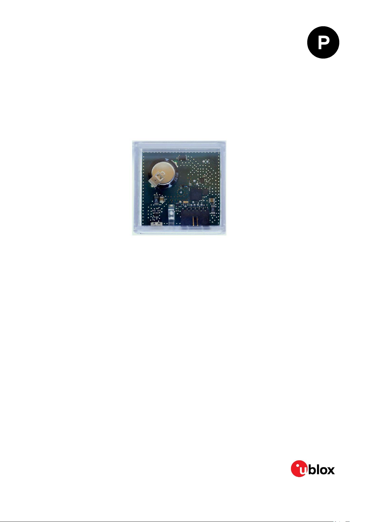
3.3 Evaluation unit
Figure 2 shows C93-M8E application board.
Figure 2: C93-M8E application board
UBX-15031067 - R04 Device description Page 6 of 23
C1-Public
Page 7

C93-M8E - User Guide
Pin no.
Assignment
1
VCC 2 TXD, GPS Transmit Data, serial data to DTE, 3 V logic level inverted
3
RXD, GPS Receive Data, serial data from DTE, 3 V logic level inverted
4
Connect to RESET pin of EVA-M8E
5
Connect to SAFEBOOT pin of EVA-M8E
6
GND
3.3.1 USB
A micro USB V2.0 compatible port is featured for data communication and power supply.
3.3.2 Pin header
The C93-M8E application board includes a 6-pin latching connector from the TE Connectivity
AMPMODU MTE series. Mating cable receptacles from this series include part numbers 5-1039605 and 5-103957-5. The 6-pin header is assigned as listed in Table 2:
Table 2: Pin header description for C93-M8E
☞ Note that the UART signals are at 3 V logic levels, suitable only for direct connection to a host
microcontroller. For connection to standard RS-232 level interfaces on PCs or other equipment,
a separate inverting level-shifter buffer must be used (e.g. MAX3232).
3.3.3 LED
On the front panel of the unit, a single blue LED may be configured to follow the receiver time pulse
signal using message UBX-CFG-TP5. The time-pulse may be configured so that the LED starts
flashing at one pulse per second during a valid GNSS fix. If there is no GNSS fix, the LED will only be
lit, without flashing. The time pulse is enabled by default in C93-M8E.
3.3.4 Backup battery
The unit includes a “Supercapacitor” type rechargeable backup battery. This is necessary to store
calibration, dead-reckoning and orbital information between operations, and it also supports Real
Time Clock (RTC) to enable immediate startup in DR mode and fast acquisition of GNSS signals.
Once fully charged, the capacitor provides around 24 hours of backup supply.
3.3.5 GNSS configuration
The C93-M8E supports GPS, QZSS, GLONASS, Galileo and BeiDou.
The GNSS to be used can be configured on u-center (View > Messages View > UBX-CFG-GNSS). For
more information, refer to the u-center User Guide [6] and the u-blox 8 / u-blox M8 Receiver
Description including Protocol Specification [5].
UBX-15031067 - R04 Device description Page 7 of 23
C1-Public
Page 8
C93-M8E - User Guide
4 Setting up
4.1 C93-M8E installation
The following sections describe the steps required to complete the C93-M8E hardware installation.
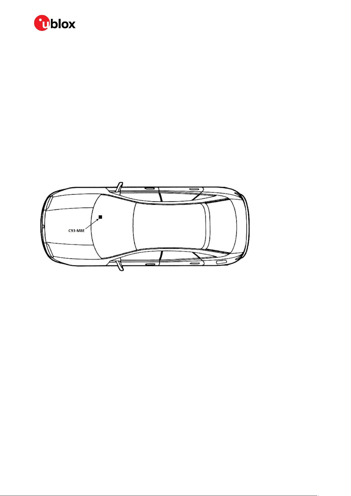
4.1.1 Mounting the C93-M8E
The C93-M8E application board should be firmly attached to the car body so as to avoid any
movement or vibration with respect to the car body. The application board should not be attached to
any “live” (unsprung) part of the vehicle’s suspension. Often it is enough to use strong double-sided
tape or Velcro tape glued to the bottom of the C93-M8E casing. The C93-M8E must be secured
against any change in position and particularly orientation with respect to the vehicle frame.
Figure 3: Example installation of the C93-M8E on car dashboard
☞ For best performance, the integrated antenna needs to have the best sky view possible in the car
or outside of the car.
4.1.2 Connecting the cables
Rather than using USB alone, we recommend using the 6-pin latching receptacle recommended
above because it locks securely to the front connector of the C93-M8E. Other 0.1" receptacles may
be compatible. You will need to solder the necessary I/O cables to signal sources and outputs as
shown in Table 3.
1. Connect the unit to a PC running Microsoft Windows by
1.1. USB: Connect via USB port or
1.2. UART: Connect via 6-pin header via an inverting RS-232 level shifter (e.g. MAX3232).
2. The device is powered either via USB or from a 5 V supply via pin no.1 of the 6-pin header.
3. Start the u-center GNSS Evaluation Software and select the corresponding COM port and baud
rate.
☞ Refer to the u-center User Guide [6] for more information.
UBX-15031067 - R04 Setting up Page 8 of 23
C1-Public
Page 9
C93-M8E - User Guide
Parameter
Description
Remark
UART Port 1, input
UBX and NMEA protocol at 9,600 Bd
UART Port 1, output
UBX and NMEA protocol at 9,600 Bd
Only NMEA messages are activated
USB, input
UBX and NMEA protocol
USB, output
UBX and NMEA protocol
Only NMEA messages are activated
4.2 Recommended configuration
For an optimum navigation performance, the recommended configuration is as follows:
Navigation rate: The default DR/GNSS-fused navigation solution update rate of 1 Hz is
recommended. You can set the navigation update rate with the message UBX-CFG-RATE. (In this
mode navigation rates of up to 30 Hz are also available from the UBX-HNR-PVT message.)
Signal attenuation compensation: For installations where the signals are attenuated due to the
C93-M8E placement, the signal attenuation compensation feature can be used to restore normal
performance. There are three possible modes:
o Disabled: no signal attenuation compensation is performed
o Automatic: the receiver automatically estimates and compensates for the signal attenuation
o Configured: the receiver compensates for the signal attenuation based on a configured value
These modes can be selected using UBX-CFG-NAVX5 message.
☞ In the case of the "configured" mode, the user should input the maximum C/N0 observed in a
clear-sky environment, excluding any outliers or unusually high values. The configured value can
have a large impact on the receiver performance, so should be chosen carefully.
☞ For more information, refer to the u-blox 8 / u-blox M8 Receiver Description including Protocol
Specification [5].
4.2.1 Serial port default configuration
Table 3: Default configuration
4.2.2 UDR configuration
By default, C93-M8E is ready to operate in UDR navigation mode. The following sections describe
how to configure the parameters specific to the installations.
☞ The statuses of different modes of UDR receiver are output in the UBX-ESF-STATUS message.
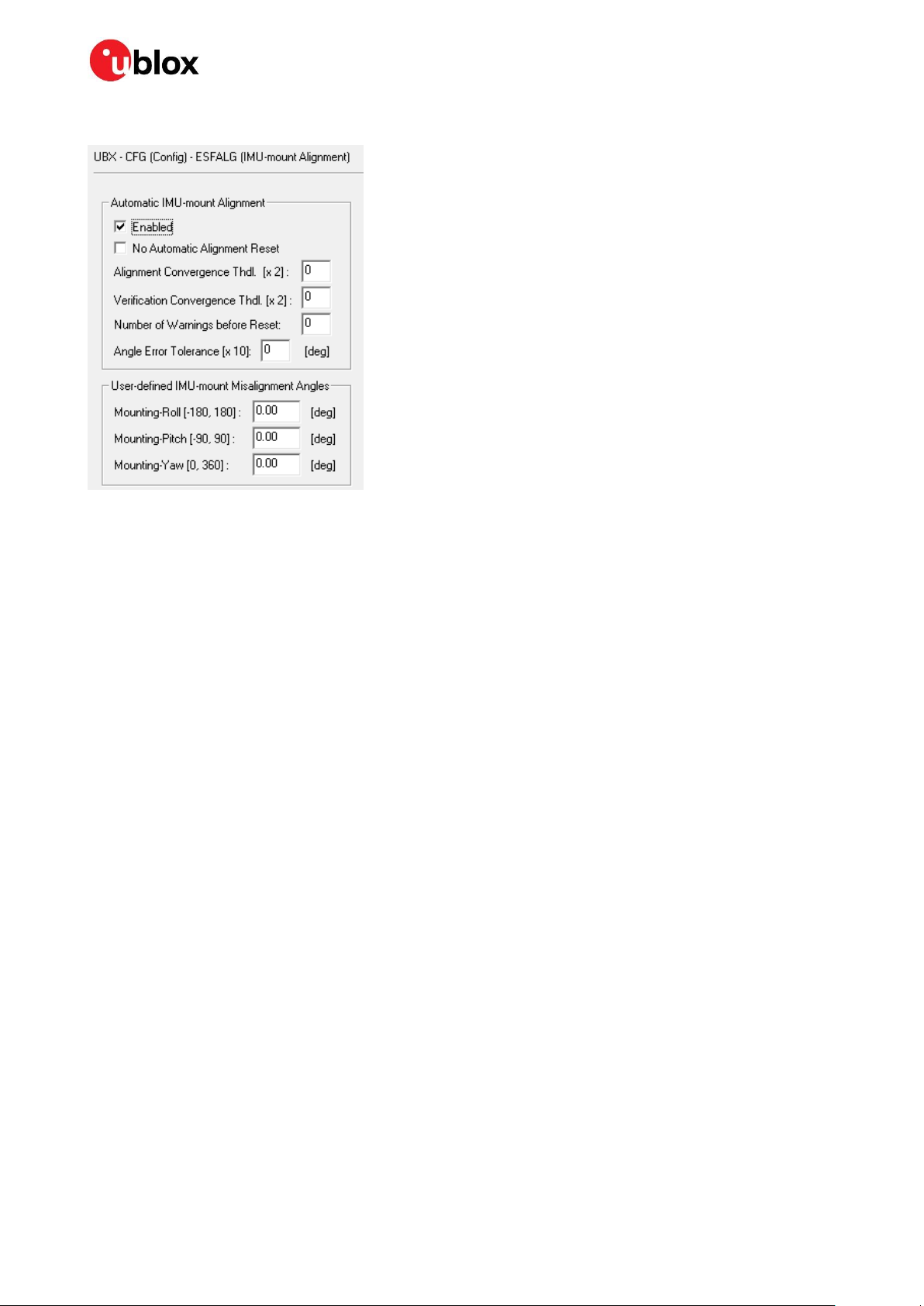
4.2.2.1 Sensor/IMU mount angles configurations
Dead reckoning performance relies on accurate configuration of the sensor mount configuration
angles. The angles may be measured and configured manually or established using the Automatic
IMU-mount Alignment feature described below. In either case the configuration is made using
message UBX-CFG-ESFALG.
If you do not know or are not completely certain how to measure the Sensor-mount Misalignment
Angles correctly, enable the Automatic IMU-mount Alignment (see below). Click the Send button
after selecting “Automatic IMU-mount Alignment”. The correct angles will then be determined
automatically in Phase II of the calibration drive (see section 4.4).
UBX-15031067 - R04 Setting up Page 9 of 23
C1-Public
Page 10
C93-M8E - User Guide
Figure 4: u-center showing how to enable Automatic IMU-mount Alignment with UBX-CFG-ESFALG
If you know the IMU-mount Misalignment Angles, enter those values into the UBX-CFG-ESFALG
dialog shown in Figure 4. Make sure the “Automatic IMU-mount Alignment” is unselected. Click the
Send button. For more information, refer to the u-blox 8 / u-blox M8 Receiver Description including
Protocol Specification [5].
☞ Automatically determined IMU-mount Alignment angles do not survive a cold start (either by
command or loss of the battery backup supply). If it is important that automatically determined
angles continue to be used after the next cold start, follow the procedure in section 4.3.1.2.
☞ If the user reverts to factory defaults with UBX-CFG-CFG command, the UBX-CFG-ESFALG with
correct configuration values (yaw, pitch, roll) shall be issued again.
4.2.2.2 Saving the configuration permanently
If, for example, automatically determined IMU mount angles should be used after the next cold start,
they can be saved in the receiver’s non-volatile memory and will be re-used until the automatic
alignment feature is next enabled. Proceed as follows:
When configuration is indicated as completed in the UBX-ESF-STATUS and UBX-ESF-ALG
windows, copy the angles from UBX-ESF-ALG display to the UBX-CFG-ESFALG dialog. Unselect
the “Automatic IMU-mount Alignment” in UBX-CFG-ESFALG dialog and click the Send button.
Save the configuration as described below.
The entire current configuration of the receiver (including configuration data and all UDR
parameters) can be saved to BBR and non-volatile memory (flash) by sending UBX-CFG-CFG
command (see Figure 5 below).
UBX-15031067 - R04 Setting up Page 10 of 23
C1-Public
Page 11

C93-M8E - User Guide
Figure 5: u-center showing how to save current configuration with UBX-CFG-CFG
4.3 UDR receiver operation
The sections below describe the UDR receiver operation modes.
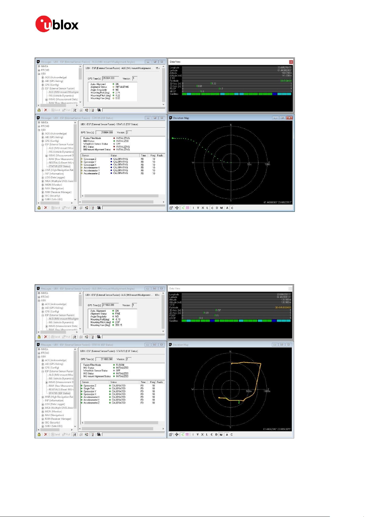
4.3.1.1 Initialization mode
The purpose of the Initialization phase is to estimate all unknown parameters that are required for
achieving fusion. In this case, the required sensor calibration status shows NOT CALIBRATED. Note
that the initialization phase requires good GNSS signal conditions as well as periods during which
vehicle is stationary and moving (including turns). Once all required initialization steps are achieved,
fusion mode is triggered and the calibration phase begins.
UBX-15031067 - R04 Setting up Page 11 of 23
C1-Public
Page 12
C93-M8E - User Guide
Figure 6: Screenshot of u-center showing the INITIALIZING mode in UBX-ESF-STATUS message
4.3.1.2 Fusion mode
Once the initialization phase is achieved, the receiver enters navigation mode and starts to compute
combined GNSS/Dead-reckoning fixes and to calibrate the sensor required for computing the fused
navigation solution. The sensor calibration status outputs CALIBRATING. As soon as the calibration
reaches a status where optimal fusion performance can be expected, the sensor calibration status
is flagged as CALIBRATED (see Figure 7).
Figure 7: Screenshot of u-center showing the sensor calibration as CALIBRATED
UBX-15031067 - R04 Setting up Page 12 of 23
C1-Public
Page 13

C93-M8E - User Guide
4.4 Accelerated initialization and calibration procedure
This section describes how to perform fast initialization and calibration of the UDR receiver for
evaluation purposes.
The duration of the initialization phase mostly depends on the quality of the GNSS signals and the
dynamics encountered by the vehicle. Therefore the car should be driven to an open and flat area
such as an empty open-sky parking area. The initialization and calibration drive should contain
phases where the car is stopped during a few minutes (with engine turned-on), phases where the car
is doing normal left and right turns, and phases where the speed is above 30 km/h under good GNSS
reception conditions.
☞ Note that the calibration status of some used sensors might fall back to CALIBRATING if the
receiver is operated in challenging conditions. In such cases, the quality of the fused navigation
will be degraded until optimal conditions are again available for re-calibrating the sensors.
☞ For more information, refer to the u-blox 8 / u-blox M8 Receiver Description including Protocol
Specification [5].
UBX-15031067 - R04 Setting up Page 13 of 23
C1-Public
Page 14

C93-M8E - User Guide
5 Test drives
We recommend recording and archiving the data of your test drives. You can enable additional debug
messages by clicking the Debug button, and then clicking the Record button (see Figure 8). When
prompted to poll for configuration, click Yes (see Figure 9).
Figure 8: The Debug and Record buttons are used for extra messages and debugging / post-analysis
Figure 9: Allow polling and storing of the receiver configuration into log file
UBX-15031067 - R04 Test drives Page 14 of 23
C1-Public
Page 15

6 Block diagram
EVA-M8E
FLASH
RTC
BACKUP
LNA + SAW
PATCH
ANTENNA
50 Ω
50 Ω
SENSORS
Power
regulator
USB (5V)
Pin header
1.65 V–3.6 V
3.3 V
Interfaces
USB
UART
Figure 10: C93-M8E block diagram
Power
C93-M8E - User Guide
UBX-15031067 - R04 Block diagram Page 15 of 23
C1-Public
Page 16
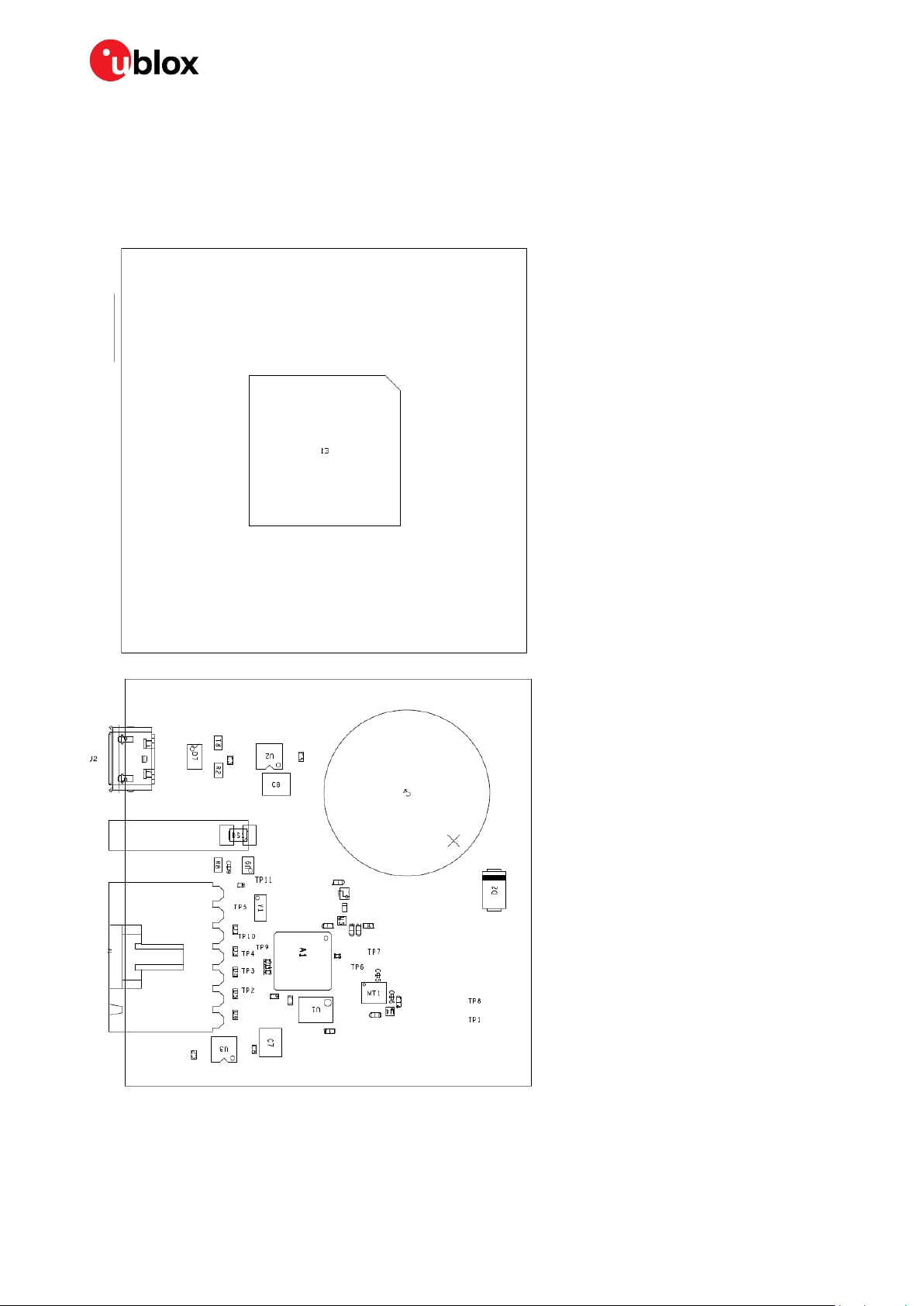
C93-M8E - User Guide
Figure 11: C93-M8E layout: top and bottom
7 Board layout
Figure 11 shows the C93-M8E board layout. See Table 4 for the application board component list.
UBX-15031067 - R04 Board layout Page 16 of 23
C1-Public
Page 17

C93-M8E - User Guide
PART
DESCRIPTION
A1
GPS RECEIVER U-BLOX EVA-M8E QFN36 -40/+85 °C
C1, C2, C3, C10, C14
C18
CAP CER X5R 0402 1U0 10% 6.3 V
C4
CAP ELECTRIC DOUBLE LAYER THT PANASONIC SERIES SG 1F 30% 5.5 V
C5, C6
CAP CER X7R 0402 10N 10% 16 V
C7, C8
CAP CER X5R 1210 10U 10% 10 V
C9
CAP CER X5R 0402 2U2 20% 6.3 V
C11
CAP CER COG 0402 1P8 +/-0.1P 25 V
C12
CAP CER COG 0402 22P 5% 25 V
C13
CAP CER X7R 0402 1N0 10% 16 V
C15, C16, C19
CAP CER X5R 0201 100N 10% 6.3 V
C17
CAP CER COG 0402 47P 5% 25 V
D1, D3, D4, D5, D6
VARISTOR BOURNS MLE SERIES CG0402MLE-18G 18 V
D2
SURFACE MOUNT SCHOTTKY BARRIER RECTIFIER SS14 1A -55/+125 °C
D7
USB DATA LINE PROTECTION ST USBLC6-2SC6 SOT23-6
DS1
LED OSRAM HYPER MINI TOPLED LB M673-L1N2-35 BLUE 0.02 A
E1
ANTENNA PATCH THT 18MM X 18MM X 4MM TAOGLAS 1561MHZ,1575MHZ,1602MHZ 40/+85 °C
FB1
FERRITE BEAD MURATA BLM15HD 0402 1000R@100 MHZ
FL1
SAW FILTER FOR GPS/GLONASS/BEIDOU TST TA1343A -40/+85°C
J1
6PIN 90\xB0 2.54MM PITCH DISCONNECTABLE CRIMP CONNECTOR -40/+85°C
J2
CON USB RECEPTACLE MICRO B TYPE SMD - MOLEX 47346-0001 - TID60001597 30V 1 A
L1
IND MURATA LQW15A 0402 8N7 3% 0.54A -55/+125 °C
MT1
SMAL, LOW POWER INERTIAL MEASUREMENT UNIT BMI160 BMI160 3.6V -40/+85 °C
R1, R2
RES THICK FILM CHIP 0603 22R 5% 0.1W -55/+125 °C
R3, R4, R5, R6
RES THICK FILM CHIP 0201 220R 5% 0.05 W
R7
RES THICK FILM CHIP 0201 1K0 5% 0.05 W
R8
RES THICK FILM CHIP 0603 100R 5% 0.1 W
U1
WINBOND W25Q16DVZPIG 16MBIT SERIAL QUAD I/O SPI FLASH MEMORY 2.7 - 3.6 V
USON8 3.6V -40/+85 °C
U2, U3
LOW DROPOUT REGULATOR LINEAR LT1962 MS8 3.3V 0.3 A
U4
LOW DROPOUT REGULATOR MICREL MIC5503 1.8V 0.3A -40/+125 °C
U5
LOW NOISE AMPLIFIER GAAS MMIC 1.575 GHZ 1.5V-3.6V JRC EPFFP6-A2 3.6V -40/+85 °C
U9
TINY LOGIC UHS BUFFER OE_N ACTIVE LOW FAIRCHILD NC7SZ125 SC70
Y1
CRYSTAL CL=7PF MICRO CRYSTAL CC7 GOLD TERMINATION 32.768KHZ 100PPM -40/+85 °C
Table 4: C93-M8E component list
UBX-15031067 - R04 Board layout Page 17 of 23
C1-Public
Page 18

8 Schematic
C93-M8E - User Guide
Figure 12: Schematic C93-M8E
UBX-15031067 - R04 C1-Public Schematic
Page 18 of 23
Page 19

C93-M8E - User Guide
9 Troubleshooting
My application (e.g. u-center) does not receive anything
Check whether the blue LED on the application board is blinking. Also make sure that the USB cable
is properly connected to the application board and the PC. By default, the application board outputs
NMEA protocol on Serial Port 1 at 9600 Bd, or on the USB.
My application (e.g. u-center) does not receive all messages
When using UART, make sure the baud rate is sufficient. If the baud rate is insufficient, GNSS
receivers based on u-blox M8 GNSS technology will skip excessive messages. Some serial port
cards/adapters (i.e. USB-to-RS232 converter) frequently generate errors. If a communication error
occurs while u-center receives a message, the message will be discarded.
My application (e.g. u-center) loses the connection to the GNSS receiver
u-blox M8 positioning technology and u-center have an autobauding feature. If frequent
communication errors occur (e.g. due to problems with the serial port), the connection may be lost.
This happens because u-center and the GNSS receiver both autonomously try to adjust the baud rate.
Do not enable the u-center autobauding feature if the GNSS receiver has the autobauding flag
enabled.
The COM port does not send any messages
Be sure that the slide switch at the front side is set to RS232 and not USB. In USB Mode the RS232
pins on the DB9 connector are switched off.
Some COM ports are not shown in the port list of my application (e.g. u-center)
Only the COM ports that are available on your computer will show up in the COM port drop down list.
If a COM Port is gray, another application running on this computer is using it.
The position is off by a few dozen meters
u-blox M8 GNSS technology starts up with the WGS84 standard GNSS datum. If your application
expects a different datum, you will most likely find the positions to be off by a few dozen meters. Do
not forget to check the calibration of u-center map files.
The position is off by hundreds of meters
Position drift may also occur when almanac navigation is enabled. The satellite orbit information
retrieved from an almanac is much less accurate than the information retrieved from the ephemeris.
With an almanac-only solution, the position will only have an accuracy of a few kilometers but it may
start up faster or still navigate in areas with obscured visibility when the ephemeris from one or
several satellites has not yet been received. The almanac information is NOT used for calculating a
position if valid ephemeris information is present, regardless of the setting of this flag.
In NMEA protocol, position solutions with high deviation (e.g. due to enabling almanac navigation) can
be filtered with the Position Accuracy Mask. UBX protocol does not directly support this since it
provides a position accuracy estimation, which allows the user to filter the position according to his
requirements. However, the “Position within Limits” flag of the UBX-NAV-STATUS message indicates
whether the configured thresholds (i.e. P Accuracy Mask and PDOP) are exceeded.
TTFF times at startup are much longer than specified
At startup (after the first position fix), the GNSS receiver performs an RTC calibration to have an
accurate internal time source. A calibrated RTC is required to achieve minimal startup time.
Before shutting down the receiver externally, check the status in MON-HW in field “Real Time Clock
Status”. Do not shut down the receiver if the RTC is not calibrated.
UBX-15031067 - R04 Contents Page 19 of 23
C1-Public
Page 20

C93-M8E - User Guide
The C93-M8E does not meet the TTFF specification
Make sure the C93-M8E has a good sky view. An obstructed view leads to prolonged startup times. In
a well-designed system, the average of the C/No ratio of high elevation satellites should be in the
range of 40 dBHz to about 50 dBHz. With a standard off-the-shelf active antenna, 47 dBHz should
easily be achieved. Low C/No values lead to a prolonged startup time.
C93-M8E does not preserve the configuration in case of removed power
u-blox M8 GNSS technology uses a slightly different concept than most other GNSS receivers do.
Settings are initially stored to volatile memory. In order to save them permanently, sending a second
command is required. This allows testing the new settings and reverting to the old settings by
resetting the receiver if the new settings aren’t good. This provides safety, as it is no longer possible
to accidentally program a bad configuration (e.g. disabling the main communication port).
UBX-15031067 - R04 Contents Page 20 of 23
C1-Public
Page 21

C93-M8E - User Guide
10 Common evaluation pitfalls
A parameter may have the same name but a different definition. GNSS receivers may have a
similar size, price and power consumption but can still have different functionalities (e.g. no
support for passive antennas, different temperature range). Also, the definitions of hot, warm and
cold start times may differ between suppliers.
Verify design-critical parameters; do not base a decision on unconfirmed numbers from data
sheets.
Try to use identical or at least similar settings when comparing the GNSS performance of different
receivers.
Data that has not been recorded at the same time and the same place should not be compared.
The satellite constellation, the number of visible satellites and the sky view might have been
different.
Do not compare momentary measurements. GNSS is a non-deterministic system. The satellite
constellation changes constantly. Atmospheric effects (i.e. dawn and dusk) have an impact on
signal travel time. The position of the GNSS receiver is typically not the same between two tests.
Comparative tests should therefore be conducted in parallel by using one antenna and a signal
splitter; statistical tests shall be run for 24 hours.
Monitor the Carrier-To-Noise-Ratio. The average C/No ratio of the high elevation satellites should
be between 40 dBHz and about 50 dBHz. A low C/No ratio will result in a prolonged TTFF and more
position drift.
When comparing receivers side by side, make sure that all receivers have the same signal levels.
The best way to achieve this is by using a signal splitter. Comparing results measured with
different antenna types (with different sensitivity) will lead to incorrect conclusions.
Try to feed the same signal to all receivers in parallel (i.e. through a splitter); the receivers will not
have the same sky view otherwise. Even small differences can have an impact on the accuracy.
One additional satellite can lead to a lower DOP and less position drift.
UBX-15031067 - R04 Contents Page 21 of 23
C1-Public
Page 22

C93-M8E - User Guide
Revision
Date
Name
Comments
R01
07-Jun-2016
njaf
Advance Information.
R02
24-Apr-2018
pmcm
Firmware Update.
R03
12-Dec-2018
njaf
Update to Early Production Information.
R04
06-Aug-2020
njaf
Update the firmware version to UDR1.31
Added 4.2.2.1 about IMU alignment configurations
Related documents
[1] EVA-M8E Data sheet, UBX-15028061
[2] EVA-M8E Hardware integration manual, UBX-15028542
[3] NEO-M8U Data sheet, UBX-15015679
[4] NEO-M8U Hardware integration manual, UBX-15016700
[5] u-blox 8 / u-blox M8 Receiver Description including Protocol Specification (Public version), UBX-
13003221
[6] u-center User Guide, UBX-13005250
☞ For regular updates to u-blox documentation and to receive product change notifications, register
on our homepage (www.u-blox.com).
Revision history
UBX-15031067 - R04 Related documents Page 22 of 23
C1-Public
Page 23

Contact
u-blox Offices
North, Central and South America
u-blox America, Inc.
Phone: +1 703 483 3180
E-mail: info_us@u-blox.com
Regional Office West Coast:
Phone: +1 408 573 3640
E-mail: info_us@u-blox.com
Technical Support:
Phone: +1 703 483 3185
E-mail: support@u-blox.com
Headquarters
Europe, Middle East, Africa
u-blox AG
Phone: +41 44 722 74 44
E-mail: info@u-blox.com
Support: support@u-blox.com
Asia, Australia, Pacific
u-blox Singapore Pte. Ltd.
Phone: +65 6734 3811
E-mail: info_ap@u-blox.com
Support: support_ap@u-blox.com
Regional Office Australia:
Phone: +61 2 8448 2016
E-mail: info_anz@u-blox.com
Support: support_ap@u-blox.com
Regional Office China (Beijing):
Phone: +86 10 68 133 545
E-mail: info_cn@u-blox.com
Support: support_cn@u-blox.com
Regional Office China (Chongqing):
Phone: +86 23 6815 1588
E-mail: info_cn@u-blox.com
Support: support_cn@u-blox.com
Regional Office China (Shanghai):
Phone: +86 21 6090 4832
E-mail: info_cn@u-blox.com
Support: support_cn@u-blox.com
Regional Office China (Shenzhen):
Phone: +86 755 8627 1083
E-mail: info_cn@u-blox.com
Support: support_cn@u-blox.com
Regional Office India:
Phone: +91 80 405 092 00
E-mail: info_in@u-blox.com
Support: support_in@u-blox.com
Regional Office Japan (Osaka):
Phone: +81 6 6941 3660
E-mail: info_jp@u-blox.com
Support: support_jp@u-blox.com
Regional Office Japan (Tokyo):
Phone: +81 3 5775 3850
E-mail: info_jp@u-blox.com
Support: support_jp@u-blox.com
Regional Office Korea:
Phone: +82 2 542 0861
E-mail: info_kr@u-blox.com
Support: support_kr@u-blox.com
Regional Office Taiwan:
Phone: +886 2 2657 1090
E-mail: info_tw@u-blox.com
Support: support_tw@u-blox.com
For complete contact information, visit us at www.u-blox.com.
UBX-15031067 - R04 Contact Page 23 of 23
C1-Public
C93-M8E - User Guide
 Loading...