

Page 1

information for
C102-F9R
Application board
User guide
Abstract
This document describes the structure and use of the C102-F9R and provides
evaluating and testing u-blox F9 high precision sensor fusion positioning technology.
UBX-20029244 - R03
C1-Public www.u-blox.com
Page 2

C102-F9R - User guide
u
document. Copying, reproduction, modification or disclosure to third parties of this document or any part thereof is only
permitted with the express wr
The information contained herein is provided “as is” and u
implied, is given, including but not limited
purpose of the information. This document may be revised by u
documents, visit www.u
Copyright © u
Document information
Title C102-F9R
Subtitle Application board
Document type User guide
Document number UBX-20029244
Revision and date R03 29-Oct-2020
Disclosure Restriction
C1-Public
This document applies to the following products:
Product name Type number Firmware version PCN reference
C102-F9R C102-F9R-0-00 HPS 1.00
C100 v1.0
C100-MSG v1.0
N/A
-blox or third parties may hold intellectual property rights in the products, names, logos and designs included in this
itten permission of u-blox.
-blox assumes no liability for its use. No warranty, either express or
to, with respect to the accuracy, correctness, reliability and fitness for a particular
-blox at any time without notice. For the most recent
-blox.com.
-blox AG.
UBX-20029244 - R03 Document information Page 2 of 32
C1-Public
Page 3

C102-F9R - User guide
Contents
Document information ................................................................................................................................ 2
Contents .......................................................................................................................................................... 3
1 Introduction ............................................................................................................................................. 5
1.1 Highlights ..................................................................................................................................................... 5
1.2 Kit includes ................................................................................................................................................... 5
1.3 System requirements ................................................................................................................................ 5
1.4 Evaluation steps .......................................................................................................................................... 5
2 Device description ................................................................................................................................. 6
2.1 USB................................................................................................................................................................. 6
2.2 UART .............................................................................................................................................................. 6
2.3 Antenna ......................................................................................................................................................... 6
2.4 14-pin front connector ............................................................................................................................... 6
2.5 10-pin rear connector ................................................................................................................................. 7
2.6 Reset and safe boot buttons .................................................................................................................... 7
2.7 I2C/SPI slide switch .................................................................................................................................... 7
2.8 LED ................................................................................................................................................................. 7
3 Setting up ................................................................................................................................................. 8
3.1 Preparation ................................................................................................................................................... 8
3.2 Installation .................................................................................................................................................... 8
3.2.1 Mounting the device and the antenna to the vehicle .................................................................. 8
3.2.2 Connecting the cables ....................................................................................................................... 8
3.3 Configuring the device ............................................................................................................................... 9
3.3.1 ADR configuration .............................................................................................................................. 9
4 Configurable CAN interface ............................................................................................................ 10
4.1 Valid configurations .................................................................................................................................10
4.2 Configuring the interface ........................................................................................................................10
4.3 C100 MSG ...................................................................................................................................................10
4.3.1 Configuration parameters ..............................................................................................................11
4.4 Configuration process ..............................................................................................................................11
4.4.1 Connections .......................................................................................................................................11
4.4.2 RealTerm ............................................................................................................................................11
4.5 Updating the MCU firmware ...................................................................................................................13
Appendix ....................................................................................................................................................... 14
A.1 CAN termination ................................................................................................................................. 14
B CAN configuration examples .......................................................................................................... 14
B.1 Wheel tick configurations ................................................................................................................ 14
B.1.1 Two rear-wheel ticks and direction ...................................................................................... 14
B.1.2 Single tick and direction .......................................................................................................... 15
B.2 Speed configurations ........................................................................................................................ 16
B.2.1 Two rear wheels and direction ............................................................................................... 16
UBX-20029244 - R03 Contents Page 3 of 32
C1-Public
Page 4

C102-F9R - User guide
B.2.2 Single speed ................................................................................................................................. 16
B.2.3 Signed speed ............................................................................................................................... 17
B.2.4 Offset speed ................................................................................................................................ 17
C Step-by-step example ...................................................................................................................... 18
D Schematic ............................................................................................................................................. 25
Related documents ................................................................................................................................... 31
Revision history .......................................................................................................................................... 31
Contact .......................................................................................................................................................... 32
UBX-20029244 - R03 Contents Page 4 of 32
C1-Public
Page 5

C102-F9R - User guide
1 Introduction
The C102-F9R application board can be used to evaluate and test the high precision sensor fusion
positioning technology of the ZED-F9R module. The built-in USB interface provides both power supply
and a high-speed communications interface. The device is compact, and it provides a flexible and
user-friendly interface between the GNSS module and test vehicles. Furthermore, it can be used with
a notebook or PC running the GUI-driven u-center application, making it the perfect companion
through all stages of evaluation and design-in phases of projects.
1.1 Highlights
• Multi-band multi-constellation GNSS
• Automotive Dead Reckoning (ADR)
• Real-time kinematic (RTK)
• Configurable CAN interface
• Dedicated pins for wheel tick and direction inputs
• USB, UART, RS-232 connections
• A short-term battery-backed RAM (BBR)
1.2 Kit includes
• Application board with enclosure
• USB cable
• Active multi-band GNSS antenna with a 5 m cable
• 14-pin breakout cable
• One-month trial license from correction service provider (available in regions defined by the
service provider)
1.3 System requirements
• A PC with Windows operating system
• u-center GNSS evaluation software
• Odometer input from vehicle
• Internet connection for correction data
1.4 Evaluation steps
Experience the lane-accurate performance of the u-blox F9R module in four simple steps:
1. Set up
2. Calibrate
3. Test
4. Analyze
UBX-20029244 - R03 Introduction Page 5 of 32
C1-Public
Page 6

C102-F9R - User guide
2 Device description
2.1 USB
A USB 2.0-compatible serial port is featured for data communication and power supply. USB drivers
are installed automatically through Windows update.
2.2 UART
The unit includes an RS-232 port which can be dynamically connected to the UARTs of the ZED-F9R
module or the MCU. Selection of the UART connection is controlled by the NEO_UART_SEL and
MCU_UART _SEL pins on the front connector.
NEO_UART_SEL MCU_UART_SEL Connected component
LOW OPEN Reserved
OPEN LOW MCU
OPEN OPEN ZED-F9R
LOW LOW None
The selected UART interface is also available via the RxD and TxD pins on the front connector.
☞ RxD and TxD pins on the front connector are at TTL voltage levels.
⚠ Flow control should not be used with the RS-232 port.
2.3 Antenna
The kit includes u-blox ANN-MB L1/L2 active multi-band GNSS antenna with a 5-meter cable. There
is a female SMA connector (RF IN) available on the front side of the unit for connecting the antenna.
⚠ Do not use the SMA connector in the back. It is reserved for future use.
2.4 14-pin front connector
The connector and its signals are described in the table below.
Pin no. Pin name I/O Level Description
14 VIN 5-24V I 5 - 24 V Power input – can be used in place of USB
13 GND Common ground pin for case-work, power and serial interface connections
12 CAN_H I Connect to the vehicle CAN high wire (ISO 11898-2)
11 CAN_L I Connect to the vehicle CAN low wire (ISO 11898-2)
10 NEO_UART_SEL I - Reserved
9 MCU_UART_SEL I - Pull-down signal for enabling UART communication with the MCU
8 TIME_MARK I Time mark input
7 WHEELTICK I 5 - 24 V Wheel tick pulse input
6 DIRECTION I 5 - 24 V Direction of travel input
5 SDA Reserved
4 SCL Reserved
3 TxD I/O 3.3 V UART TxD
2 RxD I/O 3.3 V UART RxD
1 GND_A Ground for wheel tick and direction signals
⚠ Leave the reserved pins open.
UBX-20029244 - R03 Device description Page 6 of 32
C1-Public
Page 7

C102-F9R - User guide
2.5 10-pin rear connector
This connector is used for updating the MCU firmware. See section 4.5 for more information.
2.6 Reset and safe boot buttons
The reset button on the front panel resets the unit.
The safe boot button is used to set the unit in safe boot mode. In this mode the receiver executes only
the minimal functionality, such as updating new firmware into the SQI flash. USB communication is
disabled while in safe boot mode.
To set the receiver in safe boot mode:
• Press and hold the BOOT button.
• Press the RST button.
• Release the RST button.
• Release the BOOT button.
To use UART in safe boot mode, a training sequence needs to be sent to the receiver. The training
sequence is a transmission of two bytes (0x55 0x55) at the baud rate of 9600. Wait for at least 100
milliseconds before the interface is ready to accept commands.
2.7 I2C/SPI slide switch
⚠ The switch must be kept at the I2C position to ensure correct operation of the device!
⚠ Contact u-blox technical support for assistance if required.
2.8 LED
On the front panel of the unit, a single blue LED may be configured to follow the receiver time pulse
signal. If there is no GNSS fix, the LED will be lit without flashing.
UBX-20029244 - R03 Device description Page 7 of 32
C1-Public
Page 8

C102-F9R - User guide
3 Setting up
3.1 Preparation
ADR requires odometer sensor input from the vehicle reference point (VRP), that is, wheel ticks or
speed, and direction. The following options are available:
1. WHEELTICK and DIRECTION pins
2. UBX-ESF-MEAS messages
3. CAN_H and CAN_L pins
See the ZED-F9R documentation ([1], [2]) for more information about options 1 and 2. For option 3,
refer to chapter 4.
☞ By default, the CAN bus is terminated by the unit. See appendix A.1 for how to change the
termination.
⚠ Take care when connecting to the vehicle to avoid blocking the CAN bus traffic, potentially
creating serious malfunction of the vehicle.
High-precision positioning uses RTK, which can be easily configured with the u-center NTRIP client.
Refer to the ZED-F9R documentation ([1], [2]) and u-center User guide [3] for more information.
☞ The provided correction service provider credentials are valid only in certain regions. Check the
validity of the license in your region from the correction service provider webpage.
3.2 Installation
Follow these steps to complete the installation.
3.2.1 Mounting the device and the antenna to the vehicle
Attach the device to the vehicle firmly to avoid any movement or vibration. For testing purposes, a
good location is near the VRP, that is, the center of the rear axle.
⚠ Dead reckoning performance can be seriously impaired by changes in the orientation of the device.
Place the provided GNSS antenna in a location with an unobstructed view of the sky, for example, the
roof of the vehicle. For best performance, ensure that the antenna has contact to a ground plane with
a minimum of 100–150 mm diameter.
⚠ To achieve the best possible performance, the GNSS antenna should be positioned on the vehicle
roof over the EVK. If the antenna is placed at a significant distance from the EVK, a position offset
can be introduced which might affect the accuracy of the navigation solution. To compensate for
the position offset, advanced configurations can be applied. Contact u-blox support for more
information on advanced configurations.
3.2.2 Connecting the cables
1. Connect the GNSS antenna to the RF connector on the front panel.
2. Connect the ADR signals to the related pins on the front connector:
a. Analog wheel tick and direction signals to pins WHEELTICK and DIRECTION, or
b. CAN high to CAN_H, CAN low to CAN_L.
3. Connect the device to a PC via USB for host interface and to power the device.
UBX-20029244 - R03 Setting up Page 8 of 32
C1-Public
Page 9

C102-F9R - User guide
Alternatively, host interface can be established via UART pins on the front connector or the RS-232
connector. In this case, power must be provided via USB or the VIN and GND pins on the front
connector.
☞ Use the provided 14-pin breakout cable to securely connect the front connector pins. The unused
wires must be isolated.
3.3 Configuring the device
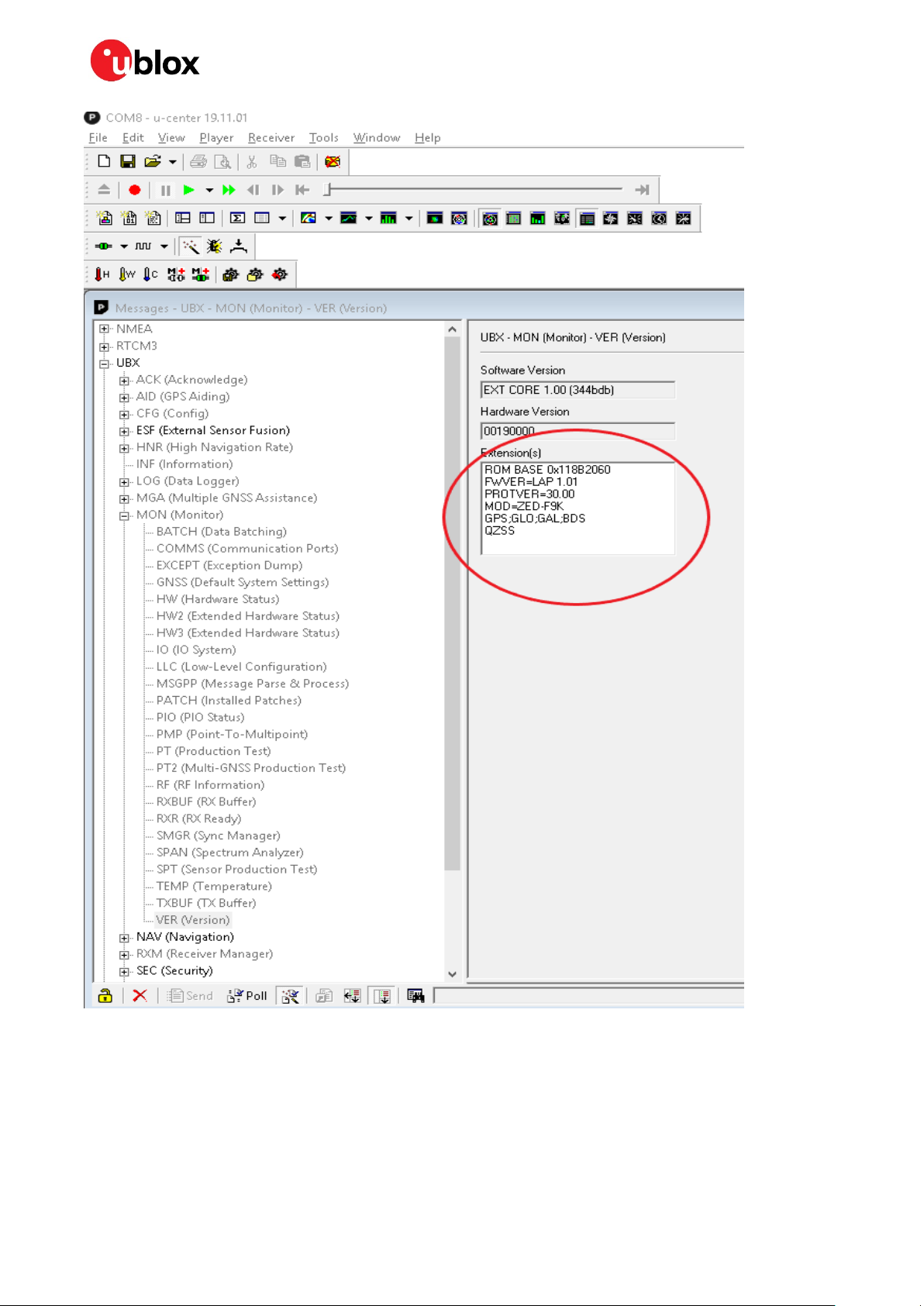
With u-center connected to the COM port assigned to the ZED-F9R module, verify that the host
interface to the ZED-F9R is established. This can be verified with u-center “Messages” view by polling
the UBX-MON-VER message. A valid response proves that the host interface is connected correctly.
3.3.1 ADR configuration
The receiver can be configured with UBX-CFG-VALSET messages. Consult the ZED-F9R
documentation ([1], [2]) for more information about the configuration.
1. Enable automatic alignment of the IMU with key ID CFG-SFIMU-AUTO_MNTALG_ENA. Set the
value to 1.
2. Configure the odometer sensor input depending on the used sensor:
a. If the wheel tick and direction pins on the front connector are used, enable the use of the wheel
tick pin by setting the value for key ID CFG-SFODO-USE_WT_PIN to 1.
b. If using the CAN interface or the software interface, the wheel tick pin must be disabled. Set
the value for key ID CFG-SFODO-USE_WT_PIN to 0. See chapter 4 for instructions on how to
configure the CAN interface.
☞ It is highly recommended to verify that the configuration is correct and to perform system sanity
checks.
UBX-20029244 - R03 Setting up Page 9 of 32
C1-Public
Page 10

C102-F9R - User guide
4 Configurable CAN interface
The device has a configurable high-speed CAN (ISO 11898-2) interface. The on-board MCU converts
the configured CAN messages into UBX-ESF-MEAS messages which are sent to the receiver via I2C.
4.1 Valid configurations
The CAN interface supports the following configurations:
• Single tick from VRP + direction
• Wheel ticks from both rear wheels + direction
• Speed from VRP + direction
• Speed from both rear wheels + direction
See appendix B for example configurations.
4.2 Configuring the interface
Communication with the MCU can be established via UART. Connect the front connector pin
MCU_UART_SEL to ground to enable the MCU communication.
The MCU UART runs at baud rate 115200.
The following messages are supported:
• CONFIG GET – Reports the current CAN configuration.
o Hex string: 0x43 0xa2 0x10 0x00 0x10 0x20
• CONFIG CLEAR – Deletes the current CAN configuration.
o Hex string: 0x43 0xa2 0x12 0x00 0x12 0x24
• CONFIG SET – Sends a configuration for one data field.
o Hex string: generate with the tool
Sending the commands to the MCU can be done through a terminal program. We recommend using
RealTerm. For more information, see [4].
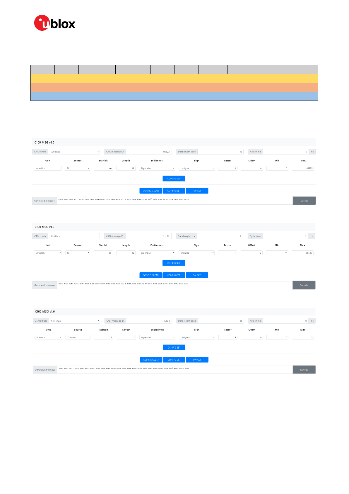
4.3 C100 MSG
C100 MSG is a browser-based tool for generating C100 MCU configuration messages for the
configurable CAN feature. It can be run entirely locally, without an internet connection. Figure 1 shows
a screenshot of the tool.
Figure 1: C100 MSG tool
UBX-20029244 - R03 Configurable CAN interface Page 10 of 32
C1-Public
Page 11

C102-F9R - User guide
The numbers in the list below refer to Figure 1:
• 1: Select the blue buttons in the middle to generate messages.
• 2: Fill these fields for CONFIG SET messages.
• 3: The generated message is displayed in the text field at the bottom. It is automatically copied to
the clipboard.
• 4: Use the decode button to parse the contents of a message pasted in the text field (3).
☞ Ensure that the version number of the tool matches the MCU firmware version. Compatibility
between versions is not guaranteed.
4.3.1 Configuration parameters
The following fields are required to generate a CONFIG SET message:
• CAN bitrate: bitrate of the CAN bus
• CAN message ID: ID of the message containing the wanted data
• Data length code: number of bytes in the CAN message
• Cycle time: time between consecutive messages
• Unit: the unit of measurement for the data
• Source: rear-left, rear-right wheel, etc.
• Startbit: index of the LSB of the value field within the CAN message
• Length: the bit-length of the value field
• Endianness: Big-endian (Motorola) or Little-endian (Intel)
• Sign: value is signed or unsigned
• Factor: scaling factor representing the value of one bit in the selected unit
• Offset: positive offset which shifts the zero point of the raw value
• Min/Forward:
o Wheel tick and speed – sets the minimum value. Values smaller than this are discarded.
o Direction – represents the value indicating forward movement
• Max/Backward:
o Wheel tick and speed – sets the maximum value. Values greater than this are discarded.
o Direction – represents the value indicating backward movement
4.4 Configuration process
Follow these steps to configure the CAN interface:
4.4.1 Connections
1. Connect the pin MCU_UART_SEL to the GND pin. Ensure that the pin NEO_UART_SEL is
disconnected.
2. Connect a PC to the MCU via RS-232 cable or the front connector UART pins.
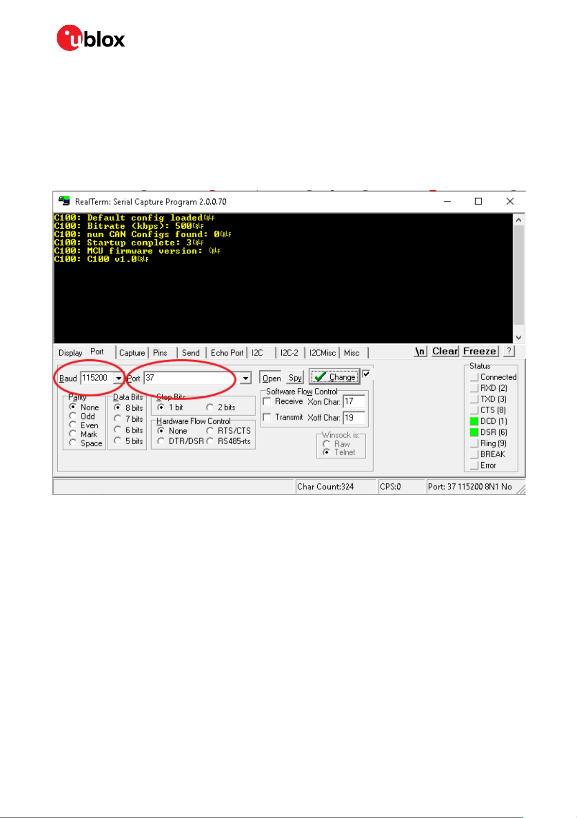
4.4.2 RealTerm
1. Select the port associated with the UART connection in the Port tab.
2. Set baud rate to 115200.
3. Apply changes by selecting the Change button. See the figure below.
UBX-20029244 - R03 Configurable CAN interface Page 11 of 32
C1-Public
Page 12

C102-F9R - User guide
Power on the device. The following startup message should be displayed in the terminal window:
4. Setting up the configurable CAN feature:
4.1. Open the RealTerm Send tab.
4.2. Generate CONFIG SET message(s) in the MSG tool.
4.3. Copy and paste a CONFIG SET message into the text field.
4.4. Send the message by selecting the Send Numbers button.
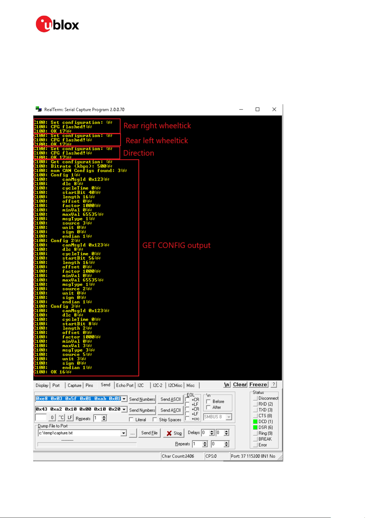
The following dialog should be displayed when a configuration has been accepted:
When all configuration messages have been sent:
4.5. Generate a CONFIG GET message.
4.6. Send the CONFIG GET message.
4.7. A dialog similar to the one shown below should be displayed and can be used to validate the
configurations.
UBX-20029244 - R03 Configurable CAN interface Page 12 of 32
C1-Public
Page 13

C102-F9R - User guide
A configuration entry can be overwritten by sending a new CONFIG SET message with the same unit
and source.
☞ All configuration entries can be deleted with the CONFIG CLEAR message.
4.5 Updating the MCU firmware
New MCU firmware and corresponding tool versions may be released e.g. to support new features or
to increase the performance of the application. To update the firmware, the following equipment is
required:
- Silicon Labs IDE or Flash Programming Utilities software [5], and
- USB debug adapter for 8-bit MCUs [6]
Follow these steps to flash the new firmware:
1. Power up the device.
2. Connect the debugger to the 10-pin rear connector.
3. If using the Silicon Labs IDE:
a. Select Debug > Connect
b. Select Debug > Download
to connect the Debugger to the MCU.
object file
and input the correct file to the opened window.
c. Select Download to start the flashing process.
4. If using Flash Programming Utilities, follow the instructions accompanying the software.
5. After the device is flashed, disconnect the debugger and reboot the device.
6. Confirm that the firmware version string matches by either checking what the MCU outputs
during bootup, or by sending a FW GET command.
UBX-20029244 - R03 Configurable CAN interface Page 13 of 32
C1-Public
Page 14

C102-F9R - User guide
Startbit
Length
Byte order
Value type
Factor
Offset
Min
Max
Unit
Source
40
16
big-endian
unsigned
1 0 0
65535
tick
RR
56
16
big-endian
unsigned
1 0 0
65535
tick
RL 8 2
big-endian
unsigned
1 0 0
3
direction
direction
Appendix
A.1 CAN termination
The CAN bus is terminated by including the jumper circled in Figure 2. The jumper is included by
default. If the termination needs to be removed, open the enclosure and remove the jumper.
Figure 2: Jumper (circled)
B CAN configuration examples
This appendix contains example CAN configurations. Each example uses the following settings for
the CAN bus:
• CAN bitrate: 500 kbps
• CAN message ID: 0x123
• DLC: 8
• Cycle time: 0 ms
The example messages are compatible with firmware C100 v1.0.
B.1 Wheel tick configurations
B.1.1 Two rear-wheel ticks and direction
This configuration uses wheel ticks from two rear wheels and a separate direction signal. The
configuration entries are described in the tables below.
UBX-20029244 - R03 Page 14 of 32
C1-Public
Page 15

C102-F9R - User guide
byte/bit 7 6 5 4 3 2 1 0 0
1 msb
lsb 2
3
4 msb
5
lsb 6 msb
7
lsb
Startbit
Length
Byte order
Value type
Factor
Offset
Min
Max
Unit
Source
32
16
big-endian
unsigned
1 0 0
65535
tick
combined 8 2
big-endian
unsigned
1 0 0
3
direction
direction
byte/bit 7 6 5 4 3 2 1 0 0
1 msb
lsb 2
3 msb
4
lsb 5
6
7
The following CONFIG SET messages are generated for this configuration:
• RR: 0x43 0xa2 0x11 0x13 0x03 0x23 0x01 0x00 0x00 0x08 0x00 0x28 0x10 0x00 0x00 0x00 0x00
0xff 0xff 0xe8 0x03 0x34 0x01 0xa9 0xa8
• RL: 0x43 0xa2 0x11 0x13 0x03 0x23 0x01 0x00 0x00 0x08 0x00 0x38 0x10 0x00 0x00 0x00 0x00
0xff 0xff 0xe8 0x03 0x24 0x01 0xa9 0x48
• dir: 0x43 0xa2 0x11 0x13 0x03 0x23 0x01 0x00 0x00 0x08 0x00 0x08 0x02 0x00 0x00 0x00 0x00
0x03 0x00 0xe8 0x03 0x5f 0x01 0xab 0x01
B.1.2 Single tick and direction
This configuration uses single-tick data and a separate direction signal. The configuration entries are
described in the tables below.
The following CONFIG SET messages are generated for this configuration:
• tick: 0x43 0xa2 0x11 0x13 0x03 0x23 0x01 0x00 0x00 0x08 0x00 0x20 0x10 0x00 0x00 0x00 0x00
0xff 0xff 0xe8 0x03 0x44 0x01 0xb1 0x68
• dir: 0x43 0xa2 0x11 0x13 0x03 0x23 0x01 0x00 0x00 0x08 0x00 0x08 0x02 0x00 0x00 0x00 0x00
0x03 0x00 0xe8 0x03 0x5f 0x01 0xab 0x01
UBX-20029244 - R03 Appendix Page 15 of 32
C1-Public
Page 16

C102-F9R - User guide
Startbit
Length
Byte order
Value type
Factor
Offset
Min
Max
Unit
Source
52
12
big-endian
unsigned
0.1 0 0
409.6
km/h
RR
56
12
big-endian
unsigned
0.1 0 0
409.6
km/h
RL 8 2
big-endian
unsigned
1 0 0
3
direction
direction
byte/bit 7 6 5 4 3 2 1 0 0
1 msb
lsb 2
3
4
5 msb
6
lsb
msb
7
lsb
Startbit
Length
Byte order
Value type
Factor
Offset
Min
Max
Unit
Source
24
8
little-endian
unsigned
1 0 0
255
mph
combined 8 2
little-endian
unsigned
1 0 0
3
direction
direction
byte/bit 7 6 5 4 3 2 1 0 0
1 msb
lsb 2
3 msb
lsb 4
5
6
B.2 Speed configurations
B.2.1 Two rear wheels and direction
This configuration uses speed from two rear wheels and a separate direction signal. The configuration
entries are described in the tables below.
The following CONFIG SET messages are generated for this configuration:
• RR: 0x43 0xa2 0x11 0x13 0x03 0x23 0x01 0x00 0x00 0x08 0x00 0x34 0x0c 0x00 0x00 0x00 0x00
0x00 0x10 0x64 0x00 0x39 0x01 0x41 0x58
• RL: 0x43 0xa2 0x11 0x13 0x03 0x23 0x01 0x00 0x00 0x08 0x00 0x38 0x0c 0x00 0x00 0x00 0x00
0x00 0x10 0x64 0x00 0x29 0x01 0x35 0x68
• dir: 0x43 0xa2 0x11 0x13 0x03 0x23 0x01 0x00 0x00 0x08 0x00 0x08 0x02 0x00 0x00 0x00 0x00
0x03 0x00 0xe8 0x03 0x5f 0x01 0xab 0x01
B.2.2 Single speed
This configuration uses a single-speed signal and a separate direction signal. The configuration
entries are described in the tables below.
UBX-20029244 - R03 Appendix Page 16 of 32
C1-Public
Page 17

C102-F9R - User guide
7
Startbit
Length
Byte order
Value type
Factor
Offset
Min
Max
Unit
Source
36
16
big-endian
signed
0.01
0
-327.68
327.67
km/h
RR
52
16
big-endian
signed
0.01
0
-327.68
327.67
km/h
RL
byte/bit 7 6 5 4 3 2 1 0 0
1
2 msb
3
4
lsb
msb
5
6
lsb 7
Startbit
Length
Byte order
Value type
Factor
Offset
Min
Max
Unit
Source
16
16
little-endian
unsigned
0.01
50
-50
605.35
mph
RR
32
16
little-endian
unsigned
0.01
50
-50
605.35
mph
RL
byte/bit 7 6 5 4 3 2 1 0 0
1
2
lsb 3 msb
4
lsb
The following CONFIG SET messages are generated for this configuration:
• speed: 0x43 0xa2 0x11 0x13 0x03 0x23 0x01 0x00 0x00 0x08 0x00 0x18 0x08 0x00 0x00 0x00
0x00 0xff 0x00 0xe8 0x03 0x4a 0x00 0xa7 0xc0
• dir: 0x43 0xa2 0x11 0x13 0x03 0x23 0x01 0x00 0x00 0x08 0x00 0x08 0x02 0x00 0x00 0x00 0x00
0x03 0x00 0xe8 0x03 0x5f 0x00 0xaa 0x00
B.2.3 Signed speed
This configuration uses a signed speed signal from both rear wheels. The configuration entries are
described in the tables below.
The following CONFIG SET messages are generated for this configuration:
• RR: 0x43 0xa2 0x11 0x13 0x03 0x23 0x01 0x00 0x00 0x08 0x00 0x24 0x10 0x00 0x00 0x00 0x80
0xff 0x7f 0x0a 0x00 0x39 0x03 0xcb 0x03
• RL: 0x43 0xa2 0x11 0x13 0x03 0x23 0x01 0x00 0x00 0x08 0x00 0x34 0x10 0x00 0x00 0x00 0x80
0xff 0x7f 0x0a 0x00 0x29 0x03 0xcb 0xa3
B.2.4 Offset speed
This configuration uses an offset speed signal from both rear wheels. The configuration entries are
described in the tables below.
UBX-20029244 - R03 Appendix Page 17 of 32
C1-Public
Page 18

C102-F9R - User guide
5
msb
6
7
The following CONFIG SET messages are generated for this configuration:
• RR: 0x43 0xa2 0x11 0x13 0x03 0x23 0x01 0x00 0x00 0x08 0x00 0x10 0x10 0x88 0x13 0x78 0xec
0x77 0xec 0x0a 0x00 0x3a 0x00 0x19 0xb2
• RL: 0x43 0xa2 0x11 0x13 0x03 0x23 0x01 0x00 0x00 0x08 0x00 0x20 0x10 0x88 0x13 0x78 0xec
0x77 0xec 0x0a 0x00 0x2a 0x00 0x19 0x52
C Step-by-step example
This step-by-step guide will use the example from section B.1.1.
Assumptions:
• User is familiar with u-center.
• USB will be used for powering the device and for the u-center interface.
• Odometer sensor measurements will be provided from the vehicle CAN bus via CAN_H and CAN_L
pins on the front connector.
• UART RS-232 connector will be used for the configurable CAN.
• RealTerm is used as the PC terminal application for the configurable CAN.
• u-center NTRIP client is used for supplying RTK corrections.
Connecting the device:
1. Connect a cable between MCU_UART_SEL and ground. This will select the MCU UART.
2. Connect UART cable to PC.
3. Connect USB cable to PC. Check that the blue light on the front panel is active.
Checking u-center:
4. Open u-center.
5. Connect to the ZED-F9R:
o Receiver > Connection > COMxx
6. Verify that the connection is established. Poll UBX-MON-VER, and check that the FWVER is
correct as shown in the figure below.
UBX-20029244 - R03 Appendix Page 18 of 32
C1-Public
Page 19
C102-F9R - User guide
7. Update ZED-F9R if necessary (Tools > Firmware Update).
UBX-20029244 - R03 Appendix Page 19 of 32
C1-Public
Page 20

C102-F9R - User guide
Configuring ZED-F9R
ZED-F9R configuration can be set with UBX-CFG-VALSET message and the appropriate
configuration keys.
8. Disable output messages on I2C (MCU is connected to I2C):
o CFG-I2COUTPROT-UBX = false
o CFG-I2COUTPROT-NMEA = false
9. Enable automatic alignment:
o CFG-SFIMU-AUTO_MNTALG_ENA = true
10. (Optional) Enable priority navigation mode (10 Hz):
o CFG-RATE-NAV_PRIO = 10
o CFG-UART1-BAUDRATE = 115200
• You need to increase UART1 baud rate if you are using the priority navigation mode.
Enabling logging/debug messages
Messages can be enabled with UBX-CFG-VALSET with CFG-MSGOUT-xx configuration keys.
The following hex string contains the recommended minimum set of debug messages required by ublox for any issues which may need investigation.
B5 62 06 8A 54 00 00 05 00 00 3E 02 91 20 01 98 02 91 20 01 9D 02 91 20 01 44 01 91 20 01 3F
01 91 20 01 39 02 91 20 01 66 02 91 20 01 26 01 91 20 01 7A 02 91 20 01 0D 01 91 20 01 08 01
91 20 01 09 00 91 20 01 18 00 91 20 01 6B 02 91 20 01 16 02 91 20 01 2F 02 91 20 01 3B 7C
☞ The debug messages are supplied here as a hex string because it contains some proprietary
messages.
11. Copy and paste the hex string into the Custom Messages field in u-center Messages view, and
select the Send button (circled in the figure below).
UBX-20029244 - R03 Appendix Page 20 of 32
C1-Public
Page 21

C102-F9R - User guide
UBX-20029244 - R03 Appendix Page 21 of 32
C1-Public
Page 22
C102-F9R - User guide
Configuring the CAN interface in RealTerm
1. Open RealTerm.
2. Select the Port tab.
3. Select the PC port corresponding to the MCU UART.
4. Set baud rate to 115200.
5. Restart the C100.
6. MCU startup dialog should appear in the terminal.
UBX-20029244 - R03 Appendix Page 22 of 32
C1-Public
Page 23
C102-F9R - User guide
Startbit
Length
Byte order
Value type
Factor
Offset
Min
Max
Unit
Source
40
16
big-endian
unsigned
1 0 0
65535
tick
RR
56
16
big-endian
unsigned
1 0 0
65535
tick
RL 8 2
big-endian
unsigned
1 0 0
3
direction
direction
Generating the CONFIG SET strings with the MSG tool
From B.1.1:
7. Use the MSG tool to generate the CONFIG SET messages.
Rear-right wheel tick:
Rear-left wheel tick:
Direction:
The following CONFIG SET messages are generated for this configuration:
• RR: 0x43 0xa2 0x11 0x13 0x03 0x23 0x01 0x00 0x00 0x08 0x00 0x28 0x10 0x00 0x00 0x00 0x00
0xff 0xff 0xe8 0x03 0x34 0x01 0xa9 0xa8
• RL: 0x43 0xa2 0x11 0x13 0x03 0x23 0x01 0x00 0x00 0x08 0x00 0x38 0x10 0x00 0x00 0x00 0x00
0xff 0xff 0xe8 0x03 0x24 0x01 0xa9 0x48
• dir: 0x43 0xa2 0x11 0x13 0x03 0x23 0x01 0x00 0x00 0x08 0x00 0x08 0x02 0x00 0x00 0x00 0x00
0x03 0x00 0xe8 0x03 0x5f 0x01 0xab 0x01
UBX-20029244 - R03 Appendix Page 23 of 32
C1-Public
Page 24
C102-F9R - User guide
Sending CONFIG SET strings to MCU:
8. Open RealTerm.
9. Select the Send tab.
10. Copy and paste the rear-right wheel tick CONFIG SET string to the RealTerm text box.
11. Select the Send Numbers button.
Verify configurations with CONFIG GET string, 0x43 0xa2 0x10 0x00 0x10 0x20.
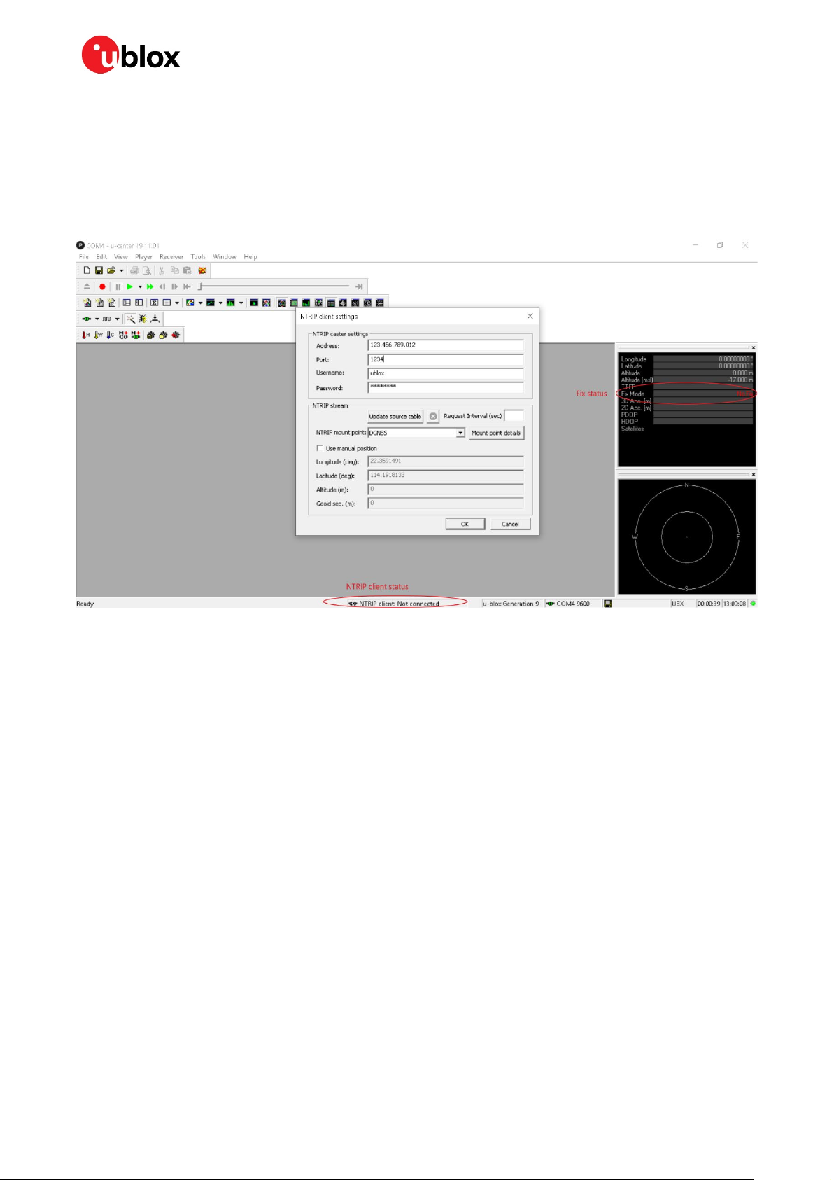
Configuring u-center NTRIP client
UBX-20029244 - R03 Appendix Page 24 of 32
C1-Public
Page 25
C102-F9R - User guide
12. Connect receiver to u-center.
13. Open NTRIP client: Receiver > NTRIP client.
14. Input correction service provider credentials.
15. Select OK.
16. NTRIP client status can be monitored in the lower part of the u-center frame, see the circle in the
figure below.
17. Fix status can be monitored with the docking windows > data view.
D Schematic
The following pages include the complete schematic for the C102-F9R board. Note that the GNSS
module in the schematic is F9K, but otherwise the schematic is accurate.
UBX-20029244 - R03 Appendix Page 25 of 32
C1-Public
Page 26

C102-F9R - User guide
UBX-20029244 - R03 Appendix Page 26 of 32
C1-Public
Page 27

C102-F9R - User guide
UBX-20029244 - R03 Appendix Page 27 of 32
C1-Public
Page 28

C102-F9R - User guide
UBX-20029244 - R03 Appendix Page 28 of 32
C1-Public
Page 29

C102-F9R - User guide
UBX-20029244 - R03 Appendix Page 29 of 32
C1-Public
Page 30

C102-F9R - User guide
UBX-20029244 - R03 Appendix Page 30 of 32
C1-Public
Page 31

C102-F9R - User guide
Related documents
[1] ZED-F9R Integration manual, UBX-20039643
[2] ZED-F9R Interface description, UBX-19056845
[3] u-center user guide, UBX-13005250
[4] RealTerm Serial Terminal, https://realterm.sourceforge.io/
[5] Silicon Labs 8-bit Microcontroller Software, https://www.silabs.com/products/development-
tools/software/8-bit-8051-microcontroller-software
[6] Silicon Labs 8-bit USB Debug Adapter, https://www.silabs.com/development-tools/mcu/8-bit/8-
bit-usb-debug-adapter
☞ For regular updates to u-blox documentation and to receive product change notifications, register
on our homepage (www.u-blox.com).
Revision history
Revision Date Name Status / Comments
R01 21-Jul-2020 jilm Initial release
R02 02-Oct-2020 jilm Corrected HPS FW number.
Added chapter 4.5 for updating the MCU FW.
Added mention about advanced DR config. application note in 3.2.1.
R03 29-Oct-2020 jilm Updated related documents
UBX-20029244 - R03 Related documents Page 31 of 32
C1-Public
Page 32

C102-F9R - User guide
Contact
For complete contact information, visit us at www.u-blox.com.
u-blox Offices
North, Central and South America
u-blox America, Inc.
Phone: +1 703 483 3180
E-mail: info_us@u-blox.com
Regional Office West Coast:
Phone: +1 408 573 3640
E-mail: info_us@u-blox.com
Technical Support:
Phone: +1 703 483 3185
E-mail: support@u-blox.com
Headquarters
Europe, Middle East, Africa
u-blox AG
Phone: +41 44 722 74 44
E-mail: info@u-blox.com
Support: support@u-blox.com
Asia, Australia, Pacific
u-blox Singapore Pte. Ltd.
Phone: +65 6734 3811
E-mail: info_ap@u-blox.com
Support: support_ap@u-blox.com
Regional Office Australia:
Phone: +61 2 8448 2016
E-mail: info_anz@u-blox.com
Support: support_ap@u-blox.com
Regional Office China (Beijing):
Phone: +86 10 68 133 545
E-mail: info_cn@u-blox.com
Support: support_cn@u-blox.com
Regional Office China (Chongqing):
Phone: +86 23 6815 1588
E-mail: info_cn@u-blox.com
Support: support_cn@u-blox.com
Regional Office China (Shanghai):
Phone: +86 21 6090 4832
E-mail: info_cn@u-blox.com
Support: support_cn@u-blox.com
Regional Office China (Shenzhen):
Phone: +86 755 8627 1083
E-mail: info_cn@u-blox.com
Support: support_cn@u-blox.com
Regional Office India:
Phone: +91 80 405 092 00
E-mail: info_in@u-blox.com
Support: support_in@u-blox.com
Regional Office Japan (Osaka):
Phone: +81 6 6941 3660
E-mail: info_jp@u-blox.com
Support: support_jp@u-blox.com
Regional Office Japan (Tokyo):
Phone: +81 3 5775 3850
E-mail: info_jp@u-blox.com
Support: support_jp@u-blox.com
Regional Office Korea:
Phone: +82 2 542 0861
E-mail: info_kr@u-blox.com
Support: support_kr@u-blox.com
Regional Office Taiwan:
Phone: +886 2 2657 1090
E-mail: info_tw@u-blox.com
Support: support_tw@u-blox.com
UBX-20029244 - R03 Contact Page 32 of 32
C1-Public
 Loading...