

Page 1

enables
.
C101-D9S
Application board (rev. C)
User guide
Abstract
This document explains the use of C101-D9S application board. The C101-D9S board
customers to evaluate L-band GNSS correction services with the NEO-D9S correction data receiver
UBX-20031865 - R01 www.u-blox.com
C1-Public
Page 2

Document information
u-blox or third parties may hold intellectual property rights in the products, names, logos and designs included in this
document. Copying, reproduction, modification or disclosure to third parties of this document or any part thereof is only
permitted with the express written permission
The information contained herein is provided “as is” and u
implied, is given, including but not limited
purpose of the information. This document may be revised by u
documents, visit www.u
Copyright © u
Title C101-D9S
C101-D9S - User guide
Subtitle
Document type
Application board (rev. C)
User guide
Document number UBX-20031865
Revision and date
R01 30-Jul-2020
Disclosure restriction C1-Public
This document applies to the following products:
Product name Type number Firmware version PCN reference
C101-D9S C101-D9S-0-00 FW V1.04 PMP 1.04 N/A
UBX-20031865 - R01 Document information Page 2 of 15
C1-Public
-blox AG.
-blox.com.
of u-blox.
-blox assumes no liability for its use. No warranty, either express or
to, with respect to the accuracy, correctness, reliability and fitness for a particular
-blox at any time without notice. For the most recent
Page 3

C101-D9S - User guide
Contents
Document information ................................................................................................................................ 2
Contents .......................................................................................................................................................... 3
1 Introduction ............................................................................................................................................. 4
1.1 Package contents ....................................................................................................................................... 4
2 C101-D9S product overview .............................................................................................................. 5
2.1 Components ................................................................................................................................................. 5
2.2 Jumpers ........................................................................................................................................................ 6
3 C101-D9S standalone operation ...................................................................................................... 7
Appendix .......................................................................................................................................................... 9
A Glossary .................................................................................................................................................... 9
B NEO-D9S L-band configurations ...................................................................................................... 9
C L-band antenna specification ............................................................................................................ 9
D NEO-D9S UART2 to Arduino pins .................................................................................................. 10
E C101-D9S schematics ...................................................................................................................... 11
Related documentation ........................................................................................................................... 14
Revision history .......................................................................................................................................... 14
Contact .......................................................................................................................................................... 15
UBX-20031865 - R01 Contents Page 3 of 15
C1-Public
Page 4

C101-D9S - User guide
1 Introduction
The C101-D9S board is a convenient tool that allows customers to become familiar with the u-blox
NEO-D9S L-band correction data receiver. The board provides facilities for evaluating the product and
demonstrating its key features.
NEO-D9S is a satellite data receiver for L-band correction broadcasts and can be configured for use
with a variety of correction services. Using such correction services enables high precision navigation
globally in multiple regions, as well as coverage across continents.
The C101-D9S application board offers:
• NEO-D9S module for use as L-band correction data receiver
• USB connection for communication and power supply
• L-band antenna connection for receiving the satellite data stream
• Arduino shield connection
1.1 Package contents
The delivered package contains:
• C101-D9S board
• L-band antenna
• Antenna ground plane (12 cm circular)
• USB interconnect cable
• Jumper connectors
Prior to using the board, it is useful to download the appropriate evaluation software and keep handy
the documents listed in the Related documents section.
UBX-20031865 - R01 Introduction Page 4 of 15
C1-Public
Page 5

C101-D9S - User guide
2 C101-D9S product overview
2.1 Components
C101-D9S houses the NEO-D9S L-band correction data receiver. The board is powered from the USB
cable connection or via Arduino shield. The main components of the board are listed below and shown
in Figure 1 and Figure 2:
• Native USB port
• FTDI USB bridge
• SMA RF connector and antenna supply capability (L-band)
• UART2 interface through Arduino shield
• NEO-D9S RESET button
• NEO-D9S SAFEBOOT button
Figure 1: C101-D9S block diagram
UBX-20031865 - R01 C101-D9S product overview Page 5 of 15
C1-Public
Page 6
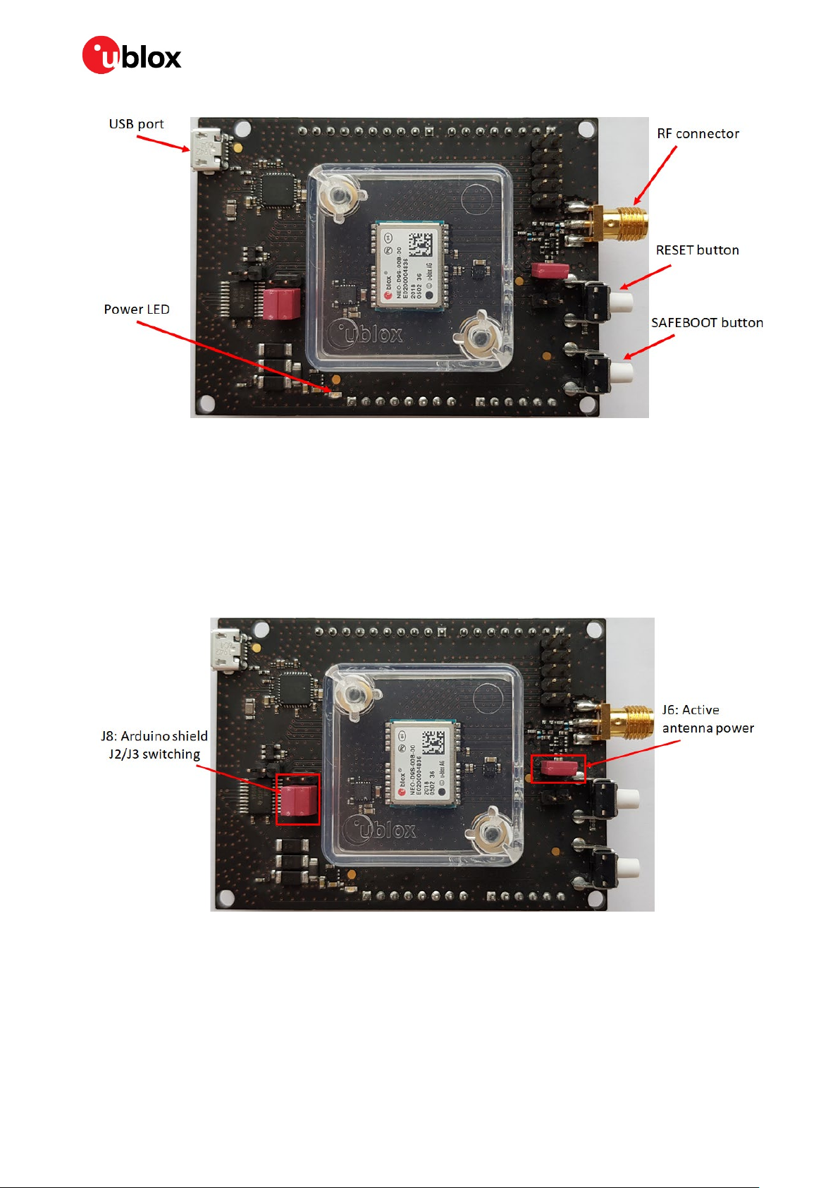
Figure 2: C101-D9S quick start basic overview
C101-D9S - User guide
2.2 Jumpers
The board is delivered with the following default jumpers:
• J6: This jumper provides 3.3 V power supply to an external active antenna plugged to the SMA RF
connector. The current limit circuit is also enabled up to 60 mA.
• J8: This jumper switches the communication from the UART2 of the NEO-D9S to the J2 or J3
connector of the Arduino shield (refer to Appendix D for further details).
Figure 3: C101-D9S jumpers overview
For further details, see the C101-D9S schematic in Appendix E.
UBX-20031865 - R01 C101-D9S product overview Page 6 of 15
C1-Public
Page 7
C101-D9S - User guide
3 C101-D9S standalone operation
This section provides some quicksteps to enable NEO-D9S standalone operation, and connecting via
u-center (see u-center user guide [3]).
• Connect the supplied L-band antenna to the RF SMA connector. Ensure good visibility of the GEO
communication satellites.
• Connect the USB to a Windows PC, this will power the board. The FTDI and USB drivers will be
installed automatically from Windows Update when the user connects the board for the first time.
• The power LED will turn on in blue color.
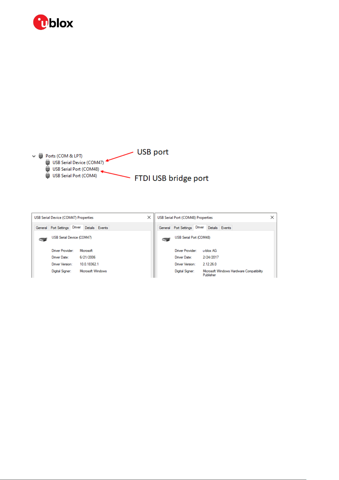
• Start the Device Manager utility from Windows. Two new ports will be visible under the Ports tab:
the USB Serial Device is the Native USB port and the USB Serial Port is the FTDI USB bridge port,
as shown in Figure
Figure 4: Windows Device Manager Ports identifications
4.
Figure 5: FTDI USB bridge and USB ports properties
• Start u-center and connect to one of the COM ports. If you are using the FTDI USB bridge, make
sure the baud rate in u-center is set to 9600.
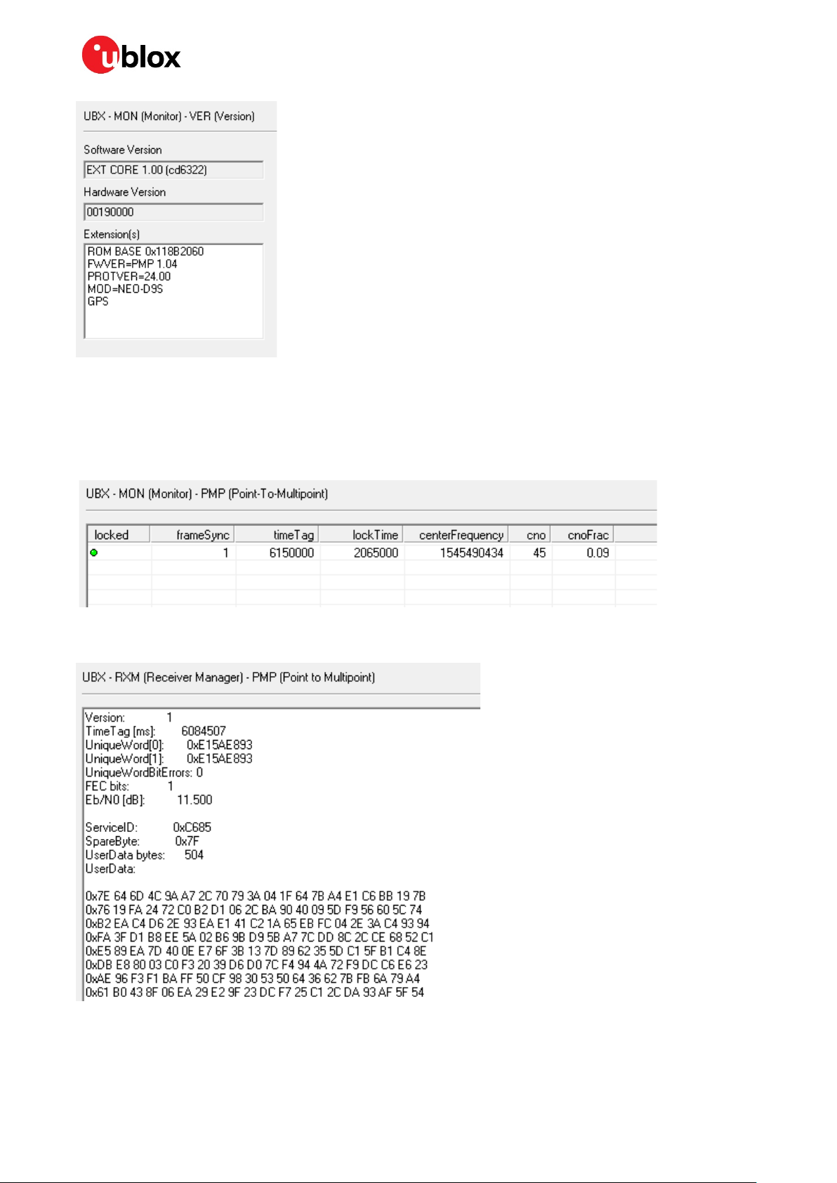
• Poll UBX-MON-VER message and check the content as shown in Figure
6.
UBX-20031865 - R01 C101-D9S standalone operation Page 7 of 15
C1-Public
Page 8
C101-D9S - User guide
Figure 6: UBX-MON-VER message
NEO-D9S needs to be properly configured to receive the L-band signal correction data. See Appendix
B for the default NEO-D9S L-band configuration, which can be adapted for other services.
The messages UBX-MON-PMP and UBX-RXM-PMP (see Figure 7 and Figure 8) can be polled or
enabled to check respectively the reception of the signal and the decoded correction data.
Figure 7: UBX-MON-PMP message
Figure 8: UBX-RXM-PMP message
UBX-20031865 - R01 C101-D9S standalone operation Page 8 of 15
C1-Public
Page 9

Appendix
A Glossary
Abbreviation Definition
FTDI Future Technology Device International
GEO Geostationary Earth Orbit
LED Light Emitting Diode
LNA Low Noise Amplifier
RF Radio Frequency
RHCP Right Hand Circular Polarized
SMA SubMiniature version A
UART Universal Asynchronous Receiver Transmitter
USB Universal Serial Bus
Table 1: Explanation of the abbreviations and terms used
C101-D9S - User guide
B NEO-D9S L-band configurations
Correction services from several providers are available via the L-band communication satellites. The
service provider will have several correction service specific configurations that need to be configured
before the receiver can provide the relevant service provider data such as:
• Service provider service ID
• Service provider frequency based on geographical location
• Service provider data rate
This means that the frequency allocation for a particular service provider could change. Service
providers do provide information on any frequency changes when required.
The NEO-D9S default L-band configuration keys are listed below:
• CFG-PMP-CENTER_FREQUENCY = 1539812500 Hz
• CFG-PMP-SEARCH_WINDOW = 2200 Hz
• CFG-PMP-USE_SERVICE_ID = 1 (true)
• CFG-PMP-SERVICE_ID = 50821
• CFG-PMP-DATA_RATE = 2400 (B2400) bps
• CFG-PMP-USE_DESCRAMBLER = 1 (true)
• CFG-PMP-DESCRAMBLER_INIT = 23560
• CFG-PMP-USE_PRESCRAMBLING = 0 (false)
• CFG-PMP-UNIQUE_WORD = 16238547128276412563
The NEO-D9S correction data receiver is fully compliant with the u-blox configuration concept. The
messages UBX-CFG-VALSET, UBX-CFG-VALGET and UBX-CFG-VALDEL are used to configure the
above keys. See the NEO-D9S Integration manual [1] for further details.
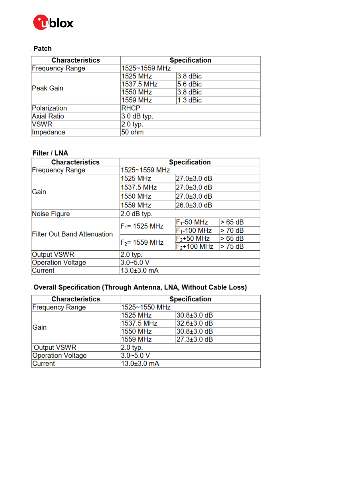
C L-band antenna specification
The following is an overview of the provided Inpaq L-band antenna, LBAND01D-S6-00:
UBX-20031865 - R01 Appendix Page 9 of 15
C1-Public
Page 10
C101-D9S - User guide
See the NEO-D9S Integration manual [1] for further details.
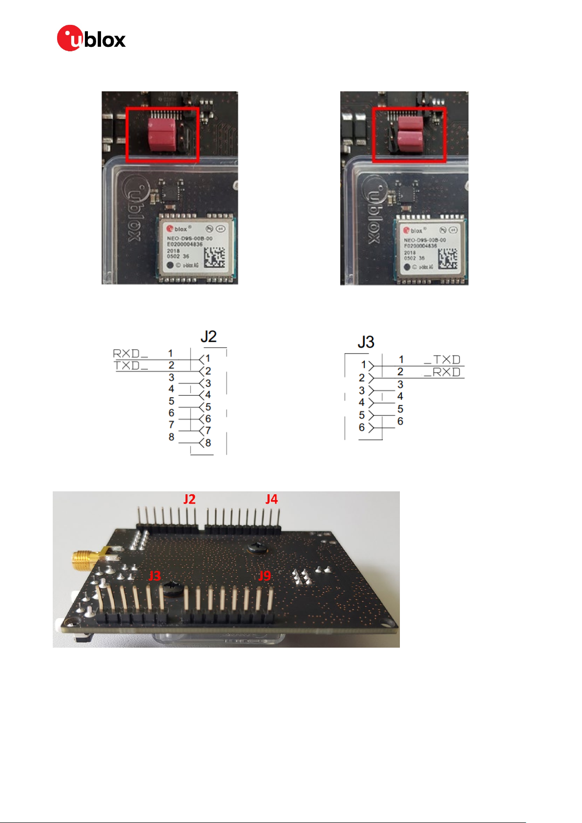
D NEO-D9S UART2 to Arduino pins
Depending on the position of the jumper J8 on the C101-D9S board, communication with the UART2
port of the NEO-D9S is enabled on the Arduino connector pins as shown below:
UBX-20031865 - R01 Appendix Page 10 of 15
C1-Public
Page 11
C101-D9S - User guide
The communication takes place through the
pins 1 and 2 of the J2 connector:
The communication takes place through the
pins 1 and 2 of the J3 connector:
Figure 9 shows the placement of the Arduino connectors on the C101-D9S board.
Figure 9: C101-D9S Arduino connectors
E C101-D9S schematics
The following pages show the complete schematics for the C101-D9S evaluation board.
UBX-20031865 - R01 Appendix Page 11 of 15
C1-Public
Page 12

C101-D9S - User guide
UBX-20031865 - R01 Appendix Page 12 of 15
C1-Public
Page 13

C101-D9S - User guide
UBX-20031865 - R01 Appendix Page 13 of 15
C1-Public
Page 14

C101-D9S - User guide
Related documentation
[1] NEO-D9S Integration manual, UBX-19026111
[2] ZED-F9P Integration manual, UBX-18010802
[3] u-center User guide, UBX-13005250
☞ For product change notifications and regular updates of u-blox documentation, register on our
website, www.u-blox.com.
Revision history
Revision Date Name Comments
R01 30-Jul-2020 dama Initial release
UBX-20031865 - R01 Related documentation Page 14 of 15
C1-Public
Page 15

Contact
For complete contact information, visit us at www.u-blox.com.
u-blox Offices
North, Central and South America
u-blox America, Inc.
Phone: +1 703 483 3180
E-mail: info_us@u-blox.com
Regional Office West Coast:
Phone: +1 408 573 3640
E-mail: info_us@u-blox.com
Technical Support:
Phone: +1 703 483 3185
E-mail: support@u-blox.com
Headquarters
Europe, Middle East, Africa
u-blox AG
Phone: +41 44 722 74 44
E-mail: info@u-blox.com
Support: support@u-blox.com
C101-D9S - User guide
Asia, Australia, Pacific
u-blox Singapore Pte. Ltd.
Phone: +65 6734 3811
E-mail: info_ap@u-blox.com
Support: support_ap@u-blox.com
Regional Office Australia:
Phone: +61 3 9566 7255
E-mail: info_anz@u-blox.com
Support: support_ap@u-blox.com
Regional Office China (Beijing):
Phone: +86 10 68 133 545
E-mail: info_cn@u-blox.com
Support: support_cn@u-blox.com
Regional Office China (Chongqing):
Phone: +86 23 6815 1588
E-mail: info_cn@u-blox.com
Support: support_cn@u-blox.com
Regional Office China (Shanghai):
Phone: +86 21 6090 4832
E-mail: info_cn@u-blox.com
Support: support_cn@u-blox.com
Regional Office China (Shenzhen):
Phone: +86 755 8627 1083
E-mail: info_cn@u-blox.com
Support: support_cn@u-blox.com
Regional Office India:
Phone: +91 80 405 092 00
E-mail: info_in@u-blox.com
Support: support_in@u-blox.com
Regional Office Japan (Osaka):
Phone: +81 6 6941 3660
E-mail: info_jp@u-blox.com
Support: support_jp@u-blox.com
Regional Office Japan (Tokyo):
Phone: +81 3 5775 3850
E-mail: info_jp@u-blox.com
Support: support_jp@u-blox.com
Regional Office Korea:
Phone: +82 2 542 0861
E-mail: info_kr@u-blox.com
Support: support_kr@u-blox.com
Regional Office Taiwan:
Phone: +886 2 2657 1090
E-mail: info_tw@u-blox.com
Support: support_tw@u-blox.com
UBX-20031865 - R01 Contact Page 15 of 15
C1-Public
 Loading...