

Page 1
blox modules in a Bluetooth
Implementing Bluetooth
mesh with u-connectXpress
software
Bluetooth mesh
Application note
Abstract
This application note describes how to use Bluetooth mesh-enabled umesh network.
UBX-19025268 - R06
C1-Public www.u-blox.com
Page 2

Implementing Bluetooth mesh with u-connectXpress software - Application note
u-blox or third parties may hold intellectual property rights in the products, names, logos and designs included in this
document. Copying, reproduction, modification or disclosure to third parties of this document or any part thereof is only
permitted with the
The information contained herein is provided “as is” and u
implied, is given, including but not limited
purpose of the information. This document may be revised by u
documents, visit www.u
Copyright © u
Document information
Title
Implementing Bluetooth mesh with u-connectXpress software
Subtitle Bluetooth mesh
Document type
Document number
Application note
UBX-19025268
Revision and date R06 12-Feb-2021
Disclosure restriction C1-Public
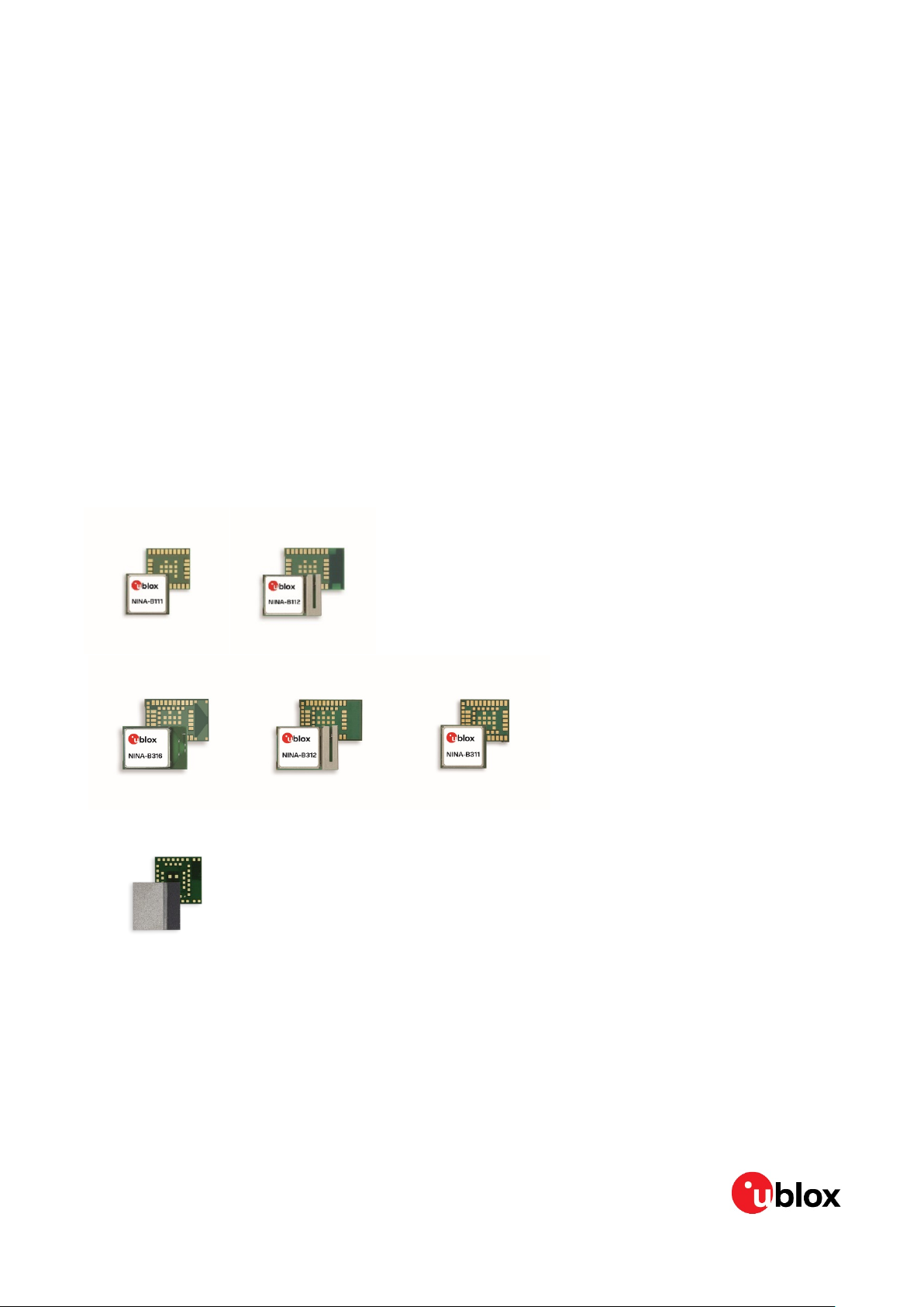
This document applies to the following products:
Product name u-connectXpress software version
ANNA-B112 MESH-2.1.0
NINA-B111 MESH-5.1.0
NINA-B112 MESH-5. 1.0
NINA-B311 v3.0.0
NINA-B312 v3.0.0
NINA-B316 v3.0.0
express written permission of u-blox.
-blox assumes no liability for its use. No warranty, either express or
to, with respect to the accuracy, correctness, reliability and fitness for a particular
-blox at any time without notice. For the most recent
-blox.com.
-blox AG.
UBX-19025268 - R06 Document information Page 2 of 41
C1-Public
Page 3

Implementing Bluetooth mesh with u-connectXpress software - Application note
Contents
Document information ............................................................................................................................. 2
Contents ....................................................................................................................................................... 3
1 Introduction .......................................................................................................................................... 7
1.1 General information about Bluetooth® mesh ....................................................................................... 7
1.2 Bluetooth mesh with u-connect software ............................................................................................. 8
1.3 Example used in this document ............................................................................................................... 8
1.4 Configuring the evaluation kits ................................................................................................................ 9
1.5 Clearing the non-volatile memory .......................................................................................................... 10
2 Mesh models in u-connectXpress software ............................................................................. 11
2.1 Introduction ................................................................................................................................................ 11
2.2 Example client model in u-connectXpress ........................................................................................... 11
2.3 Example server model in u-connectXpress .......................................................................................... 12
3 Provisioning u-connectXpress modules .................................................................................... 13
3.1 Introduction ................................................................................................................................................ 13
3.2 Provisioning using AT commands ......................................................................................................... 14
3.2.1 Client node ......................................................................................................................................... 14
3.2.2 Server node ........................................................................................................................................ 14
3.3 Provisioning using a smartphone application ..................................................................................... 15
4 Configuring u-connectXpress mesh node ................................................................................ 16
4.1 Client node .................................................................................................................................................. 16
4.2 Server node ................................................................................................................................................. 16
4.3 Remote configuration .............................................................................................................................. 16
5 Running the sample mesh network ............................................................................................ 18
Appendix .................................................................................................................................................... 20
A AT commands for Bluetooth mesh ............................................................................................. 20
A.1 Set Bluetooth mode +UBTMODE ........................................................................................................... 20
A.1.1 Description ......................................................................................................................................... 20
A.1.2 Syntax ................................................................................................................................................. 20
A.1.3 Defined values ................................................................................................................................... 20
A.1.4 Notes ................................................................................................................................................... 20
A.2 Set device info +UBTMDID ...................................................................................................................... 20
A.2.1 Description ......................................................................................................................................... 20
A.2.2 Syntax ................................................................................................................................................. 20
A.2.3 Defined values ................................................................................................................................... 21
A.3 Add Model +UBTMMOD ........................................................................................................................... 21
A.3.1 Description ......................................................................................................................................... 21
A.3.2 Syntax ................................................................................................................................................. 21
A.3.3 Defined values ................................................................................................................................... 21
A.4 Add generic model +UBTMMODG ......................................................................................................... 21
A.4.1 Description ......................................................................................................................................... 22
UBX-19025268 - R06 Contents Page 3 of 41
C1-Public
Page 4

Implementing Bluetooth mesh with u-connectXpress software - Application note
A.4.2 Syntax ................................................................................................................................................. 22
A.4.3 Defined values ................................................................................................................................... 22
A.5 Bind device key to remote configuration server +UBTMCCB .......................................................... 22
A.5.1 Description ......................................................................................................................................... 22
A.5.2 Syntax ................................................................................................................................................. 22
A.5.3 Defined values ................................................................................................................................... 23
A.6 Unbind device key of remote configuration server +UBTMCCU ..................................................... 23
A.6.1 Description ......................................................................................................................................... 23
A.6.2 Syntax ................................................................................................................................................. 23
A.6.3 Defined values ................................................................................................................................... 23
A.7 Set mesh configuration parameters +UBTMCFG .............................................................................. 23
A.7.1 Description ......................................................................................................................................... 23
A.7.2 Syntax ................................................................................................................................................. 23
A.7.3 Defined values ................................................................................................................................... 24
A.8 Mesh configuration event +UUBTMC ................................................................................................... 24
A.8.1 Description ......................................................................................................................................... 24
A.8.2 Defined values ................................................................................................................................... 24
A.9 Add opcode +UBTMOPC .......................................................................................................................... 24
A.9.1 Description ......................................................................................................................................... 24
A.9.2 Syntax ................................................................................................................................................. 24
A.9.3 Defined values ................................................................................................................................... 24
A.10 Add element +UBTMELM ........................................................................................................................ 25
A.10.1 Description ......................................................................................................................................... 25
A.10.2 Syntax ................................................................................................................................................. 25
A.10.3 Defined values ................................................................................................................................... 25
A.11 Publish opcode +UBTMPUB .................................................................................................................... 25
A.11.1 Description ......................................................................................................................................... 25
A.11.2 Syntax ................................................................................................................................................. 25
A.11.3 Defined values ................................................................................................................................... 26
A.12 Reliable publish of opcode +UBTMRPUB ............................................................................................. 26
A.12.1 Description ......................................................................................................................................... 26
A.12.2 Syntax ................................................................................................................................................. 26
A.12.3 Defined values ................................................................................................................................... 26
A.13 Reply to a message +UBTMRPY ............................................................................................................ 27
A.13.1 Description ......................................................................................................................................... 27
A.13.2 Syntax ................................................................................................................................................. 27
A.13.3 Defined values ................................................................................................................................... 27
A.14 Message event +UUBTMRCV ................................................................................................................. 27
A.14.1 Description ......................................................................................................................................... 27
A.14.2 Defined values ................................................................................................................................... 27
A.15 Publish status event +UUBTMPSE ....................................................................................................... 28
A.15.1 Description ......................................................................................................................................... 28
A.15.2 Defined values ................................................................................................................................... 28
UBX-19025268 - R06 Contents Page 4 of 41
C1-Public
Page 5

Implementing Bluetooth mesh with u-connectXpress software - Application note
A.16 Node version +UBTMVER ........................................................................................................................ 28
A.16.1 Description ......................................................................................................................................... 28
A.16.2 Defined values ................................................................................................................................... 28
A.16.3 Defined values ................................................................................................................................... 29
A.17 Define network key +UBTMNKY ............................................................................................................ 29
A.17.1 Description ......................................................................................................................................... 29
A.17.2 Syntax ................................................................................................................................................. 29
A.17.3 Defined values ................................................................................................................................... 29
A.18 Define application key +UBTMAKY ....................................................................................................... 29
A.18.1 Description ......................................................................................................................................... 29
A.18.2 Syntax ................................................................................................................................................. 29
A.18.3 Defined values ................................................................................................................................... 30
A.19 Add subscription address +UBTMSUB ................................................................................................ 30
A.19.1 Description ......................................................................................................................................... 30
A.19.2 Syntax ................................................................................................................................................. 30
A.19.3 Defined values ................................................................................................................................... 30
A.20 Delete subscription +UBTMSUBD ......................................................................................................... 30
A.20.1 Description ......................................................................................................................................... 30
A.20.2 Syntax ................................................................................................................................................. 30
A.20.3 Defined values ................................................................................................................................... 31
A.21 Add local address +UBTMADR ............................................................................................................... 31
A.21.1 Description ......................................................................................................................................... 31
A.21.2 Syntax ................................................................................................................................................. 31
A.21.3 Defined values ................................................................................................................................... 31
A.22 Clear local address +UBTMADRCLR ..................................................................................................... 31
A.22.1 Description ......................................................................................................................................... 31
A.22.2 Syntax ................................................................................................................................................. 32
A.23 Bind application key +UBTMAKB ........................................................................................................... 32
A.23.1 Description ......................................................................................................................................... 32
A.23.2 Syntax ................................................................................................................................................. 32
A.23.3 Defined values ................................................................................................................................... 33
A.24 Add publish address +UBTMPAD .......................................................................................................... 33
A.24.1 Description ......................................................................................................................................... 33
A.24.2 Syntax ................................................................................................................................................. 33
A.24.3 Defined values ................................................................................................................................... 33
A.25 Add device key +UBTMDKY .................................................................................................................... 33
A.25.1 Description ......................................................................................................................................... 33
A.25.2 Syntax ................................................................................................................................................. 33
A.25.3 Defined values ................................................................................................................................... 34
A.26 Set element model parameters +UBTMEMP ...................................................................................... 34
A.26.1 Description ......................................................................................................................................... 34
A.26.2 Defined values ................................................................................................................................... 34
A.27 Set relay status +UBTMRLY ................................................................................................................... 34
UBX-19025268 - R06 Contents Page 5 of 41
C1-Public
Page 6

Implementing Bluetooth mesh with u-connectXpress software - Application note
A.27.1 Description ......................................................................................................................................... 34
A.27.2 Syntax ................................................................................................................................................. 35
A.27.3 Defined values ................................................................................................................................... 35
A.28 Clear mesh stack flash storage +UBTMCLR ....................................................................................... 35
A.28.1 Description ......................................................................................................................................... 35
A.28.2 Syntax ................................................................................................................................................. 35
B Limitations ......................................................................................................................................... 36
C Power consumption ......................................................................................................................... 37
D Glossary .............................................................................................................................................. 38
Related documentation ......................................................................................................................... 39
Revision history ....................................................................................................................................... 40
Contact ....................................................................................................................................................... 41
UBX-19025268 - R06 Contents Page 6 of 41
C1-Public
Page 7
Implementing Bluetooth mesh with u-connectXpress software - Application note
1 Introduction
1.1 General information about Bluetooth® mesh
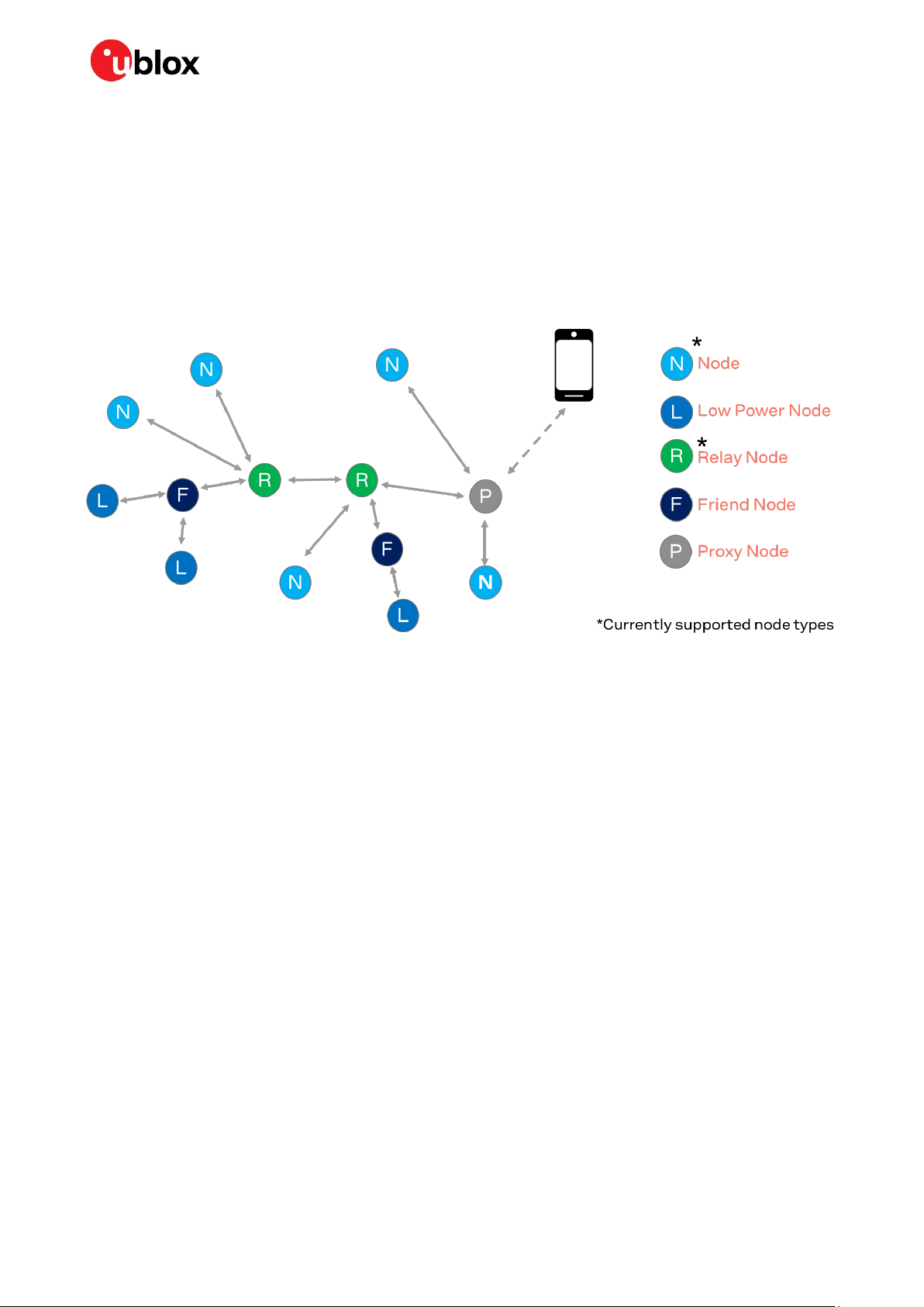
Bluetooth mesh is a specification for forming mesh networks developed by the Bluetooth SIG
(http://www.bluetooth.org). See reference [2] for additional information. It was developed to support
a number of use cases for large scale networks. The nodes can communicate using one-to-one,
one-to-many, and many-to-many communication. Each node in a Bluetooth mesh network has one of
the defined node types as shown in Figure 1.
Figure 1: Different node types in Bluetooth mesh network
The nodes communicate using messages defined by opcodes, which is a number that identifies the
message.
Each node has a “model”, which defines the functionality of the node, similar to the general structure
of a mesh node in Figure 2. The models can be generic, as is predefined in the Bluetooth mesh
standard, or proprietary and defined by the implementer. With u-connect software, the models for the
node functionality can be provided using AT commands and letting an external MCU handle the logic
of the node, as described in chapter 2.
To add a device to a mesh network, you need to “provision” it, meaning you give it an address on the
network and add crypto keys for the network; see chapter 3 for a detailed description. Information
about the “configuration” of a node, or how to add publish and subscription addresses for the models
in the node are also provided in chapter 3.
UBX-19025268 - R06 Introduction Page 7 of 41
C1-Public
Page 8
Implementing Bluetooth mesh with u-connectXpress software - Application note
Node
Subscriptions
Elements
Publication
Models
Figure 2: Elements and models in Bluetooth mesh
In a mesh node that is based on u-connect software, define the models first and then provision and
configure the node.
For more information about Bluetooth Mesh in general, see [2] and [3].
Operations
(Opcodes)
Per model;
Get (read), Set (write), Set
Unacked and
Status operations
1.2 Bluetooth mesh with u-connect software
Bluetooth mesh can be used with u-connectXpress software. With u-connectXpress software, you
need to add an external MCU to handle events.
This application note will describe how to:
• Use u-connectXpress software in a Bluetooth mesh network
• Provision and configure a u-blox module running u-connectXpress for a Bluetooth mesh network
The applicable software versions are listed on page 2 in this document. Separate mesh-enabled
software is used in ANNA-B1 and NINA-B1 products.
The limitations of mesh-enabled u-connectXpress software and u-connectXpress software in mesh
mode are described in appendix B.
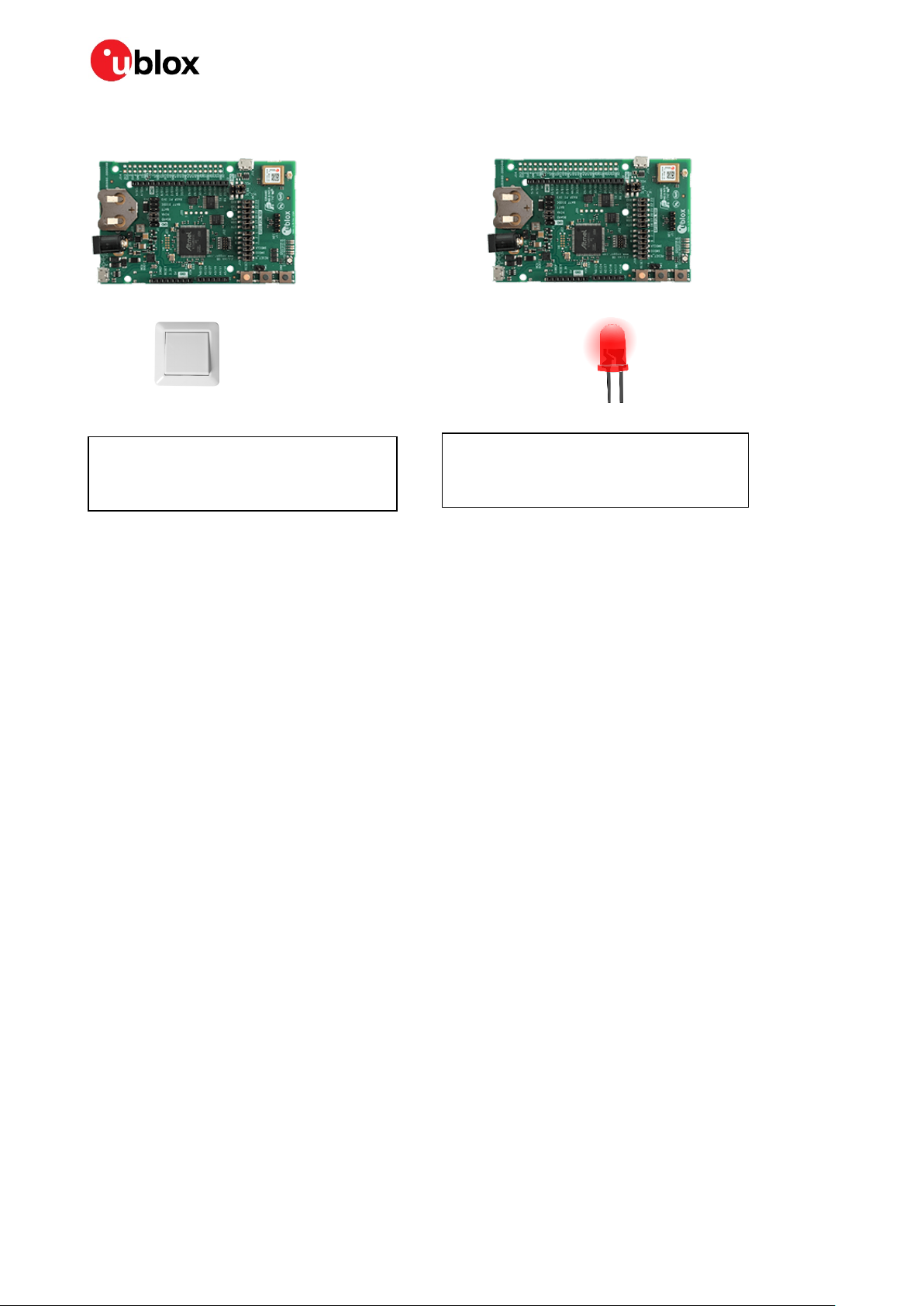
1.3 Example used in this document
This document provides sample instructions for building a very small mesh network with two nodes
using u-connect software. The sample setup has one server node and one client node. The server node
will implement an OnOff server that enables turning on or off an LED over the mesh network,
corresponding to a mesh-enabled lightbulb or smart-plug.
Both the server and client are running on NINA-B3 Evaluation kits.
UBX-19025268 - R06 Introduction Page 8 of 41
C1-Public
Page 9
Implementing Bluetooth mesh with u-connectXpress software - Application note
OnOff client
Address: 0x5002
Implemented using u-connectXpress
Figure 3: Overview of the sample application
For details on the NINA-B3 evaluation kits, see the EVK-NINA-B3 user guide [9].
OnOff server
Address: 0x5000
Implemented using u-connectXpress
1.4 Configuring the evaluation kits
This section provides information on how to configure the nodes in order to communicate on the same
network and with the applications running on each node.
A node in a mesh network needs to go through a number of stages in order to be functional:
1. Define models and opcodes for node
2. Provision node with keys in order to connect to a Bluetooth mesh network
3. Configure node with publish and subscribe addresses
This document describes the various configuration steps in the following chapters:
1. One evaluation kit is configured as a client in chapter 2.2.
2. One evaluation kit is configured as a server in chapter 2.3.
3. The kits are provisioned with network keys in chapter 3.
4. The kits are configured with addresses in chapter 4.
5. In chapter 5 the example is run using AT commands.
☞ All u-connect software mesh nodes have the Bluetooth mesh relay node functionality enabled by
default so that it is possible to easily extend this example to several nodes.
UBX-19025268 - R06 Introduction Page 9 of 41
C1-Public
Page 10

Implementing Bluetooth mesh with u-connectXpress software - Application note
1.5 Clearing the non-volatile memory
During development, more than just AT+UFACTORY is required to make a complete factory reset,
including removing all mesh configuration, provisioning data and model definitions:
# 1) Clear the mesh stack’s flash memory (provisioning) and clear the local unicast address:
AT+UBTMCLR
# The module will restart again
AT+ UBTMADRCLR
AT&W
AT+CPWROFF
# The module will restart again
# 2) Clear the model definition:
AT+UFACTORY
AT+CPWROFF
If it is only desired to go to an unprovisioned state, step 1 above is enough. In that case, the previously
defined model is kept.
☞ Note that this action may have implications on the network you are using. Normally it is not
allowed to reuse an address until the network keys have been changed, so this should only be done
when the whole network is reset.
UBX-19025268 - R06 Introduction Page 10 of 41
C1-Public
Page 11
Implementing Bluetooth mesh with u-connectXpress software - Application note
Sensors and actuators
2 Mesh models in u-connectXpress software
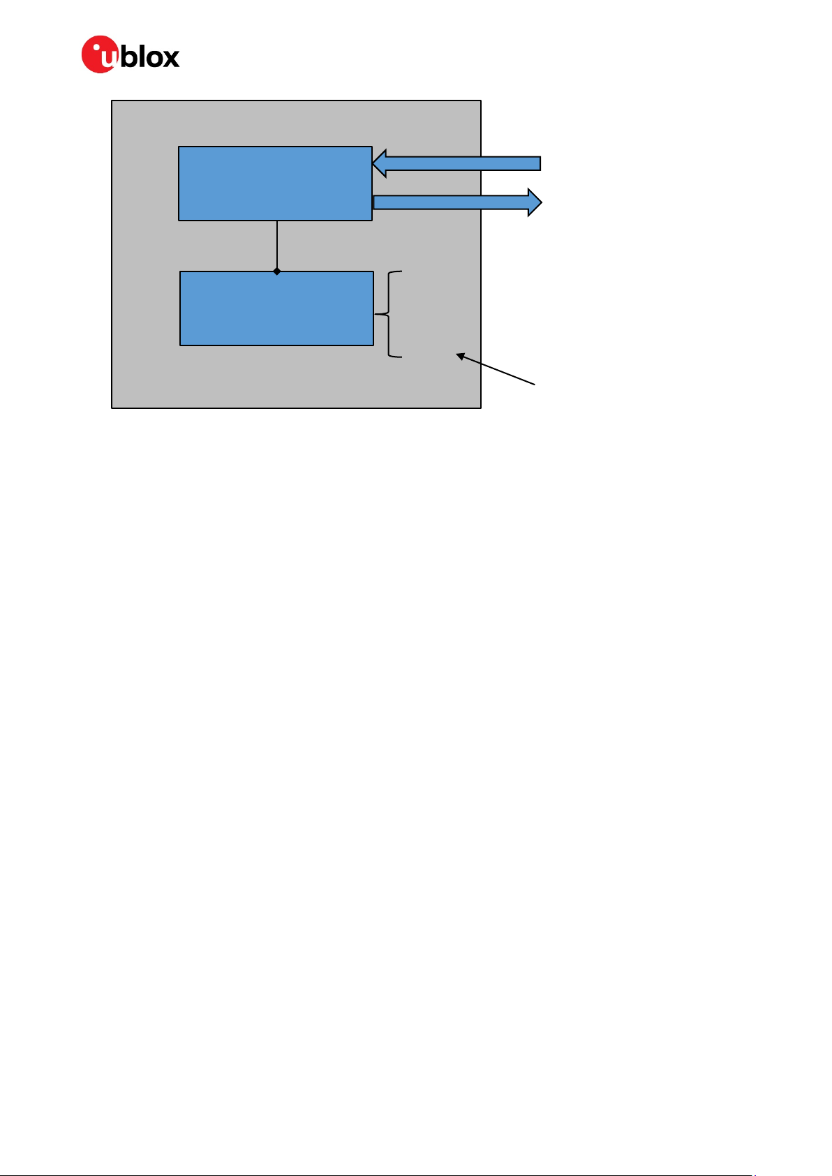
2.1 Introduction
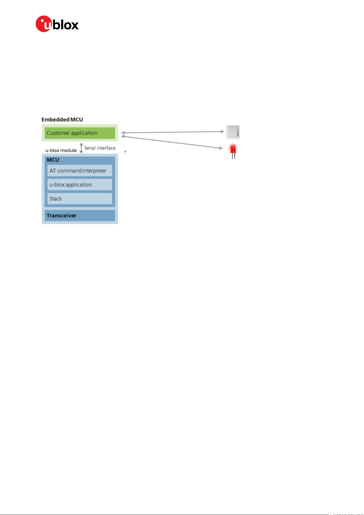
In u-connectXpress, the functionality of the models is implemented using AT commands and the logic
must reside on an external MCU. The external MCU communicates over a serial interface (UART)
using AT commands as shown in Figure 4.
Figure 4: Software architecture of u-connectXpress
The mesh functionality in u-connectXpress is implemented using AT commands described in the
u-connect AT commands manual [1].
u-connectXpress nodes can be configured easily using the s-center application [6] from u-blox;
however, any terminal application that can connect to a UART can also be used. If you are unfamiliar
with u-connectXpress, watch the introductory video provided in reference [7].
Before the model definition can start you need to set the module in mesh mode:
# Set module in Bluetooth Low Energy + mesh mode
AT+UBTMODE=6
AT&W
AT+CPWROFF
For AT command examples and further information about the parameters, see appendix A.
2.2 Example client model in u-connectXpress
In this section a Generic OnOff client is defined in the u-connectXpress node.
When using the predefined Bluetooth SIG models, messages need not be added explicitly as they are
already included in the stored model. The models are identified using the numbers as described in the
Mesh Model Specification [2]. The Generic OnOff client has the SIG Model ID - 0x1001.
# Model index 0, Generic OnOff client
AT+UBTMMODG=0,1001
AT+UBTMELM=0,0
AT&W
AT+CPWROFF
As shown above, add a generic model (AT+UBTMMODG) and then instantiate it to an element on the node
(
AT+UBTMELM). Then, store the new model and element and restart the node.
The node is now ready to be provisioned and configured as described in sections 3.2.1 and 4.1.
UBX-19025268 - R06 Mesh models in u-connectXpress software Page 11 of 41
C1-Public
Page 12

Implementing Bluetooth mesh with u-connectXpress software - Application note
If using a proprietary model, define the model and its associated messages using AT+UBTMMOD and
define your opcodes using
AT+UBTMOPC, see appendix A for additional information.
2.3 Example server model in u-connectXpress
The code examples in this chapter implement the Generic OnOff Server as described in section 1.3.
The Generic OnOff server has the SIG Model ID - 0x1000, see the Mesh Model Specification [2].
# Model index 0, Generic OnOff Server
AT+UBTMMODG=0,1000
AT+UBTMELM=0,0
AT&W
AT+CPWROFF
UBX-19025268 - R06 Mesh models in u-connectXpress software Page 12 of 41
C1-Public
Page 13

Implementing Bluetooth mesh with u-connectXpress software - Application note
3 Provisioning u-connectXpress modules
3.1 Introduction
A mesh node needs to be provisioned with the following:
• Network key(s)
• Device key
• Application key(s)
• Unicast Address
A u-blox mesh module can be provisioned either using AT commands or a smartphone application.
The configuration step is needed in order to give the u-blox module some information that is specific
to the elements and models configured on the module, such as:
• Publishing address for messages
• Connecting application keys to the model instances
• Subscription addresses
Provisioning and configuration is done after the node is loaded with the initial models.
The node goes through the following five states during the provisioning and configuration, as
described in Table 1.
State Description
0 Node completely empty. Add elements and opcodes followed by store and reboot (AT&W + AT+CPWROFF). This is
described in chapter 2.
1 Internal structures built. Needs a new reboot with AT+CPWROFF
2 Node can now be provisioned with AT commands or via GATT proxy (smartphone app)
3 Node is provisioned but needs to be configured for publish/subscribe. AT+UBTMCLR will bring node back to State 2
4 Node subscribes to at least one address. AT+UBTMCLR will bring node back to State 2
Table 1: State transitions during the setup of a mesh node
The AT commands shown in Table 1 are described in the u-connect AT commands manual [1] or as
specific mesh commands in Appendix A.
The u-connectXpress nodes are provisioned and configured either using AT commands over UART or
the nRF Mesh application [4] as described in the following sections.
After provisioning, the module has enough information to connect to the local mesh network but
needs further configuration regarding binding application keys to models, publishing and
subscription.
For the initial release of the u-connect software, the module must subscribe to at least one address
(could be a dummy address) to reach the configuration state 4 mentioned in Table 1.
UBX-19025268 - R06 Provisioning u-connectXpress modules Page 13 of 41
C1-Public
Page 14

Implementing Bluetooth mesh with u-connectXpress software - Application note
3.2 Provisioning using AT commands
See the u-connect AT commands manual [1] for more information on the AT commands used. Keys
for your own network can be generated from an online UUID generator.
Note that this example uses the same Network Key and Application Key for the nodes to be able to
communicate with each other, we also use the same Device Key which is not necessary.
3.2.1 Client node
Below is an example of provisioning a module using AT commands. This is the client node in our
example:
# Set network key index 0
AT+UBTMNKY=0,5F5F6E6F726469635F5F73656D695F5F
# Define application key index 0, network index 0
AT+UBTMAKY=0,0,5F116E6F726469635F5F73656D695F5F
# Set unicast address for node (only 1 address in this example). Address 5002 (see
chapter 1.3)
AT+UBTMADR=5002,1
# Set Device Key for node
AT+UBTMDKY=000102030405060708090A0B0C0D0E0F
# Store and reset
AT&W
AT+CPWROFF
3.2.2 Server node
This example provisions a server that can be controlled by a client provisioned according to the
example in section 3.2.1:
# Set network key index 0 (same as client module)
AT+UBTMNKY=0,5F5F6E6F726469635F5F73656D695F5F
# Define application key index 0, network index 0 (same as client module)
AT+UBTMAKY=0,0,5F116E6F726469635F5F73656D695F5F
# Set unicast address for node (only 1 address in this example). Address 5000 (see
chapter 1.3)
AT+UBTMADR=5000,1
# Set Device Key for node (can be different from other module, here a single key is used
for simplicity)
AT+UBTMDKY=000102030405060708090A0B0C0D0E0F
# Store and reset
AT&W
AT+CPWROFF
UBX-19025268 - R06 Provisioning u-connectXpress modules Page 14 of 41
C1-Public
Page 15
Implementing Bluetooth mesh with u-connectXpress software - Application note
3.3 Provisioning using a smartphone application
The u-blox mesh nodes can also be configured using the nRF Mesh application available through
Google Play Store [4] and Apple App Store [5].
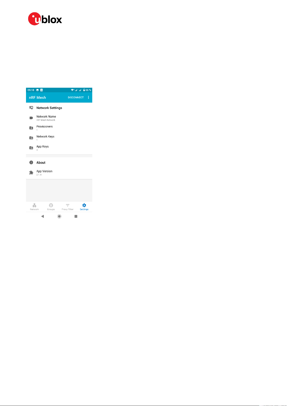
In order to provision using the smartphone application, set up your network key and application keys
(or predefined keys) in the Settings tab of the application, as shown in Figure 5.
Figure 5 nRF mesh settings
The next step is to find and provision all the nodes on your network. The application will automatically
add all unprovisioned nodes that support provisioning over GATT and let you provision them with the
keys and a unicast address.
UBX-19025268 - R06 Provisioning u-connectXpress modules Page 15 of 41
C1-Public
Page 16

Implementing Bluetooth mesh with u-connectXpress software - Application note
4 Configuring u-connectXpress mesh node
The configuration of a mesh node is done via AT commands. Example of the items that need to be
configured are:
• Binding application keys to instantiated models
• Set up publishing addresses for instantiated models
• Add subscriptions for status messages from specific elements
4.1 Client node
# Bind element 0, model 0, to application key 0
AT+UBTMAKB=0,0,0
# Set publishing address for OnOff client address 0x5000 (Server node)
AT+UBTMPAD=0,0,5000
# Restart module
AT+CPWROFF
4.2 Server node
# Bind element 0, model 0, to application key 0
AT+UBTMAKB=0,0,0
# Dummy subscription address to take node to state 4, see Table 1
# In this example we use a group address for subscription
AT+UBTMSUB=0,0,C001
# Restart module
AT+CPWROFF
4.3 Remote configuration
The remote configuration feature is a convenient way to change the configuration of a mesh node
over the mesh network.
The remote configuration is done by sending configuration messages from a Configuration Client to
a Configuration Server on the node that is to be configured.
The Configuration Client needs to have access to the device key of the node that is to be configured.
All nodes have a Configuration Server Model enabled by default, but the Configuration Client model
needs to be enabled. In order to remotely configure a node in the Bluetooth mesh network, a
Configuration client node must be added to another node in the network. For information about the
Configuration Server model, see the Mesh Profile Specification [2].
The following example shows how to add a Configuration Client model to the client that configures
the OnOff server node (commands added to previously described configurations are shown in
italic
):
# Set module in Bluetooth Low Energy + mesh mode
AT+UBTMODE=6
AT&W
AT+CPWROFF
# Model index 0, SIG ID 0x1001 Generic OnOff client
AT+UBTMMODG=0,1001
AT+UBTMELM=0,0
UBX-19025268 - R06 Configuring u-connectXpress mesh node Page 16 of 41
C1-Public
Page 17

Implementing Bluetooth mesh with u-connectXpress software - Application note
# SIG ID 0x0001 Configuration Client
AT+UBTMMODG=1,0001
AT+UBTMELM=1,1
AT&W
AT+CPWROFF
# Add network key, device key an application key
AT+UBTMNKY=0,5F5F6E6F726469635F5F73656D695F5F
AT+UBTMAKY=0,0,5F116E6F726469635F5F73656D695F5F
# Note that we have 2 addresses due to the 2 models on the node
AT+UBTMADR=5002,2
AT+UBTMDKY=000102030405060708090A0B0C0D0E0F
AT&W
AT+CPWROFF
# Bind element 0, model 0, to application key 0
AT+UBTMAKB=0,0,0
# Set publishing address for OnOff client address 0x5000 (Server node)
AT+UBTMPAD=0,0,5000
AT+CPWROFF
# Bind configuration server address and device key
AT+UBTMCCB=1,1,5000,000102030405060708090A0B0C0D0E0F
# Send “Config Relay Get” Message
AT+UBTMRPUB=1,1,8026,8028,5,99
# Config Server responds with “Config Relay Status”. 0100 => Relay active
+UUBTMRCV:FF,1,1,8028,1,5000,1,5003,5,-29,0100
UBX-19025268 - R06 Configuring u-connectXpress mesh node Page 17 of 41
C1-Public
Page 18

Implementing Bluetooth mesh with u-connectXpress software - Application note
Client
Server
AT+UBTMPUB=0,0,8202,0100
AT+UBTMRPY=00,8204,0100
Server turns on light
AT+UBTMPUB=0,0,8203,0000
Server turns off light
AT+UBTMRPY=00
AT+UBTMPUB=0,0,8201
AT+UBTMRPY=00,8204,00000
Server returns status
# Turn on LED by sending Generic OnOff Set
AT+UBTMPUB=0,0,8202,0100
# Client sends Generic OnOff Set, Light
AT+UBTMRPY=00,8204,0100
# Server node responds with Generic OnOff
53,01
5 Running the sample mesh network
The very small mesh network should now be set up and ready to run.
Messages can be sent from the client node using AT commands from a terminal application, for
example s-center.
This small example covers three simple use cases:
1. Turn on the LED.
2. Turn off the LED using unacknowledged Set.
3. Query the LED value.
This example does not light any LED as none are available. The messages sent between the client and
server nodes are shown in Figure 6.
Figure 6 Messages sent when operating simple mesh network
Further information about the sequence messages and unsolicited events sent to the host are shown
in Table 2.
Client Node Server Node
(0x8202) with parameter 01 (On) and TID 00
Status (0x8204).
# +UUBTMRCV:FF,0,0,8204,1,5000,1,5002,5,-
UBX-19025268 - R06 Running the sample mesh network Page 18 of 41
C1-Public
LED and reply with status
# +UUBTMRCV:00,0,0,8202,1,5002,1,5000,5,52,0100
Page 19

Implementing Bluetooth mesh with u-connectXpress software - Application note
AT+UBTMPUB=0,0,8203,0000
# Client sends Generic OnOff set
AT+UBTMRPY=00
# No status message for unacknowledged set
# Query LED value by sending Generic OnOff
AT+UBTMPUB=0,0,8201
# Client sends Generic OnOff Get, reply
AT+UBTMRPY=00,8204,0000
# Server node responds with Generic OnOff
53,00
Client Node Server Node
# Turn off LED by sending Generic OnOff Set
Unacknowledged (0x8203)
# with parameter 00 (Off) + TID 00
Get (0x8201)
Status (0x8204).
# +UUBTMRCV:FF,0,0,8204,1,5000,1,5002,5,-
Table 2 Example usage of Bluetooth mesh network
Unacknowledged
# +UUBTMRCV:00,0,0,8203,1,5002,1,5000,5,52,0000
# No status message sent, but reception
acknowledged to stack
with Generic OnOff Status
# +UUBTMRCV:00,0,0,8201,1,5002,1,5000,5,52,
UBX-19025268 - R06 Running the sample mesh network Page 19 of 41
C1-Public
Page 20

Implementing Bluetooth mesh with u-connectXpress software - Application note
AT+UBTMODE = <mode>
AT+UBTMODE?
+UBTMODE:<mode>
OK
ERROR
AT+UBTMDID = <company ID>, <product ID>, <version ID>
AT+UBTMDID?
+UBTMDID:<company ID>, <product ID>, <version ID>
OK
ERROR
Appendix
A AT commands for Bluetooth mesh
A.1 Set Bluetooth mode +UBTMODE
AT command Description
Add node composition data
A.1.1 Description
Set the mode of the module.
A.1.2 Syntax
Response Description
Successful write response
Error Response
A.1.3 Defined values
Parameter Type Default value Min. value Max. value Description
mode Integer - 0 0x7 Bit mask setting BT mode.
Bit 0: BT classic (N/A)
Bit 1: BT LE
Bit 2: BT mesh
Set BT mesh + BT LE for
combined usage
(AT+UBTMODE=6)
A.1.4 Notes
This command requires a Store (AT&W) and Restart (AT+CPWROFF) to take effect.
A.2 Set device info +UBTMDID
AT command Description
Add node composition data
A.2.1 Description
Set the parameters that identify the node when a provisioner is preparing to provision the node.
A.2.2 Syntax
Response Description
UBX-19025268 - R06 Appendix Page 20 of 41
C1-Public
Successful write response
Error Response
Page 21

Implementing Bluetooth mesh with u-connectXpress software - Application note
AT+UBTMMOD=<model index>,<Type>,<company ID>,<model ID>
AT+ UBTMMOD =<model index>
+UBTMMOD:<number of opcodes>,<Type>,<Company Id>
<Model Id>,<opcode >[<opcode>[…]]
OK
ERROR
AT+UBTMMODG=<model index>,<model ID>
A.2.3 Defined values
Parameter Type Default value Min. value Max. value Description
company ID Byte array
2 octets
product ID Byte array
2 octets
version ID Byte array
2 octets
- 0x0000 0xFFFF 16-bit company identifier
assigned by the Bluetooth SIG
- 0x0000 0xFFFF 16-bit vendor-assigned product
identifier
- 0x0000 0xFFFF 16-bit vendor-assigned product
version identifier
A.3 Add Model +UBTMMOD
AT command Description
Adds a model
Reads model at index <model index>
A.3.1 Description
Defines and adds a model. The model can later be instantiated to an element through AT+UBTMELM.
A.3.2 Syntax
Response Description
Read response
Successful write response
Error Response
A.3.3 Defined values
Parameter Type Default value Min value Max value Description
Model index Integer - 0 14/29 The Index the module will be
saved in
Type Integer 0 0 1 0: Server model
1: Client Model
Company ID Byte array
2 octets
Model ID Byte array
2 octets
Number of opcodes Integer
opcode Byte array
2 octets
- 0 0xFFFF Bluetooth SIG Company
Identifier
- 0 0xFFFF vendor-assigned model
identifier
Opcodes are added to the
model via AT+UBTMOPC
command.
☞ For more information about the max limits for parameters, see Appendix B.
A.4 Add generic model +UBTMMODG
AT command Description
Adds a generic SIG model
UBX-19025268 - R06 Appendix Page 21 of 41
C1-Public
Page 22

Implementing Bluetooth mesh with u-connectXpress software - Application note
OK
ERROR
AT+UBTMCCB=<element index>,<model
index>,<remote address>,<device key>
OK
ERROR
A.4.1 Description
Add a generic model and its corresponding opcodes, as specified in Mesh Model Specification 1.0 [2].
The opcodes can be listed using
element through
AT+UBTMLELM.
AT+ UBTMMOD =<model index>. The model is later instantiated to an
A.4.2 Syntax
Response Description
Successful write response
Error Response
A.4.3 Defined values
Parameter Type Default value Min value Max value Description
Model index Integer - 0 14/29 The Index the module will
be saved in
Model ID Byte array
2 octets
- 0 0xFFFF SIG assigned identifier
☞ For more information about the max limits for parameters, see Appendix B.
A.5 Bind device key to remote configuration server +UBTMCCB
AT command Description
Bind device key to a remote configuration server
A.5.1 Description
Binds a device key of a remote Configuration Server to a Configuration Client on the local node. The
local node shall first define a Configuration Client model (e.g. using
shall then be instantiated on element 1 (or higher).
After defining the model
AT+UBMCCB can be used as preparation to send Configuration Server
commands to the remote node.
Example:
AT+UBTMRPUB=1,1,8026,8028,5,99
This command requests the relay status of the remote node using Config Relay Get with the expected
answer message Config Relay Status.
Added device keys are stored in persistent memory. Only one remote Configuration Server can be
configured at the time.
key positions are occupied.
AT+UBTMCCB sets the current remote server and will return ERROR if all device
AT+UBTMCCU can be called to free up a device key position.
For more information on the configuration commands available please see the Mesh Profile
Specification [2].
AT+UBTMMODG=1,0001). The model
A.5.2 Syntax
Response Description
UBX-19025268 - R06 Appendix Page 22 of 41
C1-Public
Successful write response
Error Response
Page 23

Implementing Bluetooth mesh with u-connectXpress software - Application note
AT+UBTMCCU=<remote address>
OK
ERROR
AT+UBTMCFG=<param_tag>, <param_val>
AT+UBTMCFG=<param_tag>
AT+UBTMCFG
+UBTMCFG: <param_tag>, <param_val>
OK
ERROR
A.5.3 Defined values
Parameter Type Default value Min value Max value Description
Element Index Integer - 0 19/58 Element index to add
Model index Integer - 0 14/29 The Index the module will
be saved in
Remote address Byte array
2 bytes
Device Key Byte array
16 octets
- 0 0xFFFF Address
- - - The device key
☞ For more information about the max limits for parameters, see Appendix B.
A.6 Unbind device key of remote configuration server
+UBTMCCU
AT command Description
Unbinds the key from remote address.
A.6.1 Description
Unbinds the key from the remote address and frees a device key position for use by AT+UBTMCCB.
A.6.2 Syntax
Response Description
Successful write response
Error Response
A.6.3 Defined values
Parameter Type Default value Min value Max value Description
Remote address Byte array
16 octets
- - - Remote address
A.7 Set mesh configuration parameters +UBTMCFG
AT command Description
Write Bluetooth mesh configuration
Read Bluetooth mesh configuration for tag
Read Bluetooth mesh configuration for all tags
A.7.1 Description
Configures Bluetooth mesh parameters. The values are kept in volatile memory and will have an
immediate effect.
A.7.2 Syntax
Response Description
UBX-19025268 - R06 Appendix Page 23 of 41
C1-Public
One row per applicable tag.
Successful write response
Error Response
Page 24

Implementing Bluetooth mesh with u-connectXpress software - Application note
+UUBTMC:<event type>,<data>
Description
AT+UBTMOPC=<model index>,<opcode>
Adds an opcode to an existing model
OK
ERROR
A.7.3 Defined values
Param tag Default value Min value Max value Description
1 - - - Output power for originator role.
Valid values are:
-40, -20, -16, -12, -8, -4, 0, 2, 3, 4,
5, 6, 7 and 8 dBm.
2 Output power for relay role. Valid
values are:
-40, -20, -16, -12, -8, -4, 0, 2, 3, 4,
5, 6, 7 and 8 dBm
.
A.8 Mesh configuration event +UUBTMC
AT command Description
Mesh configuration event
A.8.1 Description
This event is sent when an external actor, such as an app running on a smartphone, provisions the
node or adds a new application key.
A.8.2 Defined values
Parameter Type Description
Event type Integer 0: Provisioning complete
1: Application Key added
Data Byte array Byte array, 2 bytes in length.
Event type 0: unicast address
Event type 1: application key index
A.9 Add opcode +UBTMOPC
AT command
A.9.1 Description
Add an opcode to a previously defined model. The opcodes of the model can be listed using AT+
UBTMMOD =<model index>.
A.9.2 Syntax
Response Description
Successful write response
Error Response
A.9.3 Defined values
Parameter Type Default value Min value Max value Description
Model index Integer - 0 14/29 The Index the module will be
opcode Byte array
2 octets
UBX-19025268 - R06 Appendix Page 24 of 41
C1-Public
saved in
- - - Bluetooth SIG or Vendor
specific Opcode
Page 25

Implementing Bluetooth mesh with u-connectXpress software - Application note
AT+UBTMELM=<element index>,<model index>
AT+UBTMLELM=<element index>
OK
ERROR
+UBTMELM:<number of
models>,<modelix>[<modelix>[…]]
AT+UBTMPUB=<element index>, <model
index>, <opcode>, [<data>]
OK
ERROR
☞ For more information about the max limits for parameters, see Appendix B.
A.10 Add element +UBTMELM
AT command Description
Add a model to an element.
Reads models linked to element at index <element index>
A.10.1 Description
Add the model at model index to the element at the given element index. Creates a new element if
necessary or adds the model to an existing element.
A.10.2 Syntax
Response Description
Successful write response
Error Response
A.10.3 Defined values
Parameter Type Default value Min value Max value Description
Element Index Integer - 0 19/58 Element index to add
model index (1..n) Integer - 0 14/29 The model index as
specified in
AT+UBTMMOD
number of models Integer
model ix Byte array
1 octet
Hexadecimal model index
☞ For more information about the max limits for parameters, see Appendix B.
A.11 Publish opcode +UBTMPUB
AT command Description
Publishes the data
A.11.1 Description
Publishes an access layer message to the publish address of the model instance.
A.11.2 Syntax
Response Description
UBX-19025268 - R06 Appendix Page 25 of 41
C1-Public
Successful write response
Error Response
Page 26

Implementing Bluetooth mesh with u-connectXpress software - Application note
AT+UBTMRPUB=<element index>, <model
<timeout>,<reliable ID>, [<data>]
OK
ERROR
A.11.3 Defined values
Parameter Type Default value Min value Max value Description
Element index Integer - 0 19/58 Index of the element
Model index Integer - 0 14/29 Index of the model
Opcode Byte array
2 octets
data Byte array
Max 128 bytes
- - - Bluetooth SIG or Vendor specific
Opcode
- - - Message to be published
☞ For more information about the max limits for parameters, see Appendix B.
A.12 Reliable publish of opcode +UBTMRPUB
AT command Description
Starts publishing a reliable message
index>, <opcode>, <reply opcode>,
A.12.1 Description
Start publishing a reliable message.
A.12.2 Syntax
Response Description
Successful write response
Error Response
A.12.3 Defined values
Parameter Type Default value Min value Max value Description
Element index Integer - 0 19/58 Index of the element
Model Index Integer 0 14/29 Index of the model
Opcode Byte array
2 octets
Reply Opcode Byte array
2 octets
Timeout Integer - 0 60 The time (sec ) until the message is
Reliable ID Integer - 0 0xFF The ID of this message that will be
data Byte array
Max 255 bytes
- - - Bluetooth SIG or Vendor specific
Opcode
- - - Bluetooth SIG or Vendor specific
Opcode
timed out
sent back in the status event (user
defined)
- - - Message to be published
☞ For more information about the max limits for parameters, see Appendix B.
UBX-19025268 - R06 Appendix Page 26 of 41
C1-Public
Page 27

Implementing Bluetooth mesh with u-connectXpress software - Application note
AT+UBTMRPY=<event
handle>[,<opcode>,<data>]
OK
ERROR
+UUBTMRCV:<event handle>,<element index>,
value>, <RSSI>,<data>
A.13 Reply to a message +UBTMRPY
AT command Description
Reply to a message received with the event +UUBTMRCV
A.13.1 Description
Reply to a reliable GET or SET. Shall also be called (without the optional parameters) after receiving a
status message.
Messages with event handle 0xFF do not need a reply.
A.13.2 Syntax
Response Description
Successful write response
Error Response
A.13.3 Defined values
Parameter Type Default value Min value Max value Description
Event handle Integer - - - The handle received with
+UUBTMRCV which this
command will reply to
Opcode Byte array
2 octets
Data Byte array
Max 128 bytes
- - - Bluetooth SIG or Vendor specific
Opcode
- - - The reply message
A.14 Message event +UUBTMRCV
AT Event Description
<model index>,<opcode>,<source address
type>, <source address>,<destination
address type>, <destination address>,<TTL
A.14.1 Description
An unsolicited event from the mesh stack. It contains a message to an instance of a model with the
given opcode. The user must always, with the exceptions described below, reply to this event with an
AT+UBTMRPY command. The reply shall use the event handle.
• Unsolicited messages that are received from a group address do not need to be replied to.
• Reply messages themselves, for example a Generic OnOff Status message, do not need a reply.
• These kind of messages have the event handle “FF”.
A.14.2 Defined values
Parameter Type Description
Event handle Integer The event handle which will be used with the reply message.
element index Integer Index of the element
Model index Integer Index of the model
opcode Byte array Bluetooth SIG or Vendor specific Opcode
An unsolicited event from the mesh stack
UBX-19025268 - R06 Appendix Page 27 of 41
C1-Public
Page 28

Implementing Bluetooth mesh with u-connectXpress software - Application note
+UUBTMPSE=<reliable ID>,<status>
AT+UBTMVER=<version ID>
AT+ UBTMVER?
Parameter Type Description
2 octets
source address type Integer 0: Invalid
1: Unicast
2: Virtual*
3: Group
source address Byte array
2 octets
destination address type Integer 0: Invalid
destination address Byte array
2 octets
TTL value Integer TTL (number of hops)
RSSI Integer RSSI value for last hop in mesh network
data Byte array
Max 128 bytes
Source address of the message
1: Unicast
2: Virtual*
3: Group
* Virtual addresses are not supported yet
Destination address of the message
The message
A.15 Publish status event +UUBTMPSE
AT event Description
An unsolicited event sent when an AT+UBTMRPUB fails or is cancelled
A.15.1 Description
This event is sent when a reliable publish message times out or has been cancelled by the user.
A.15.2 Defined values
Parameter Type Description
Reliable ID Integer The ID passed by the user when calling AT+UBTMRPUB
status Integer 1: timed out
2: cancelled*
* Cancelling a reliable message is not supported yet
A.16 Node version +UBTMVER
AT command Description
Sets a user defined value for the version of this node
Reads the current version and node configuration status
A.16.1 Description
Set a number that identifies the version of this node. The meaning and usage of the version number
is free to be defined by the user.
Reads the version number.
A.16.2 Defined values
Parameter Type Default value Min value Max value Description
Version ID Integer 0 0 0xFFFFFFFF The user defined version ID
UBX-19025268 - R06 Appendix Page 28 of 41
C1-Public
Page 29

Implementing Bluetooth mesh with u-connectXpress software - Application note
+UBTMVER:<Version ID>,
<Config status>
AT+UBTMNKY=<netkey index>,<netkey>
OK
ERROR
AT+UBTMAKY=<appkey index>,
<netkey index>,<appkey>
OK
ERROR
A.16.3 Defined values
Parameter Type Default value Min value Max value Description
Version ID Integer 0 0 0xFFFFFFFF The user defined version ID
Config status Integer - 0 4 0: Node empty
1: Models and elements step #1
2: Models and elements finished
3: Provisioned
4: Configured (at least partially)
A.17 Define network key +UBTMNKY
AT command Description
Define network key
A.17.1 Description
Add a subnetwork and its associated network key index.
A.17.2 Syntax
Response Description
Successful write response
Error Response
A.17.3 Defined values
Parameter Type Default value Min value Max value Description
netkey index Integer - 0 0xFFFF The network key index of the
subnetwork being added
netkey Byte array
16 octets
- - - The network key
A.18 Define application key +UBTMAKY
AT command Description
Define application key for the node
A.18.1 Description
Add an application key and its associated key index to a subnetwork.
A.18.2 Syntax
Response Description
Successful write response
Error Response
UBX-19025268 - R06 Appendix Page 29 of 41
C1-Public
Page 30

Implementing Bluetooth mesh with u-connectXpress software - Application note
AT+UBTMSUB=<element index>,<model
index>,<subscription address>
OK
ERROR
AT+UBTMSUBD=<element index>,<model
index>,<subscription address>
OK
ERROR
A.18.3 Defined values
Parameter Type Default value Min value Max value Description
appkey index Integer - 0 0xFFFF The application key index of the
application key being added
netkey index Integer - 0 0xFFFF The index of the subnetwork this
application key belongs to
appkey Byte array
16 octets
- - - The application key
A.19 Add subscription address +UBTMSUB
AT command Description
Add subscription address
A.19.1 Description
Add the specified address to the global subscription list and immediately starts a subscription for the
model instance defined by the specified element.
☞ For information about the limitations related to the number of publish and subscription
addresses, see Appendix B.
A.19.2 Syntax
Response Description
Successful write response
Error Response
A.19.3 Defined values
Parameter Type Default value Min value Max value Description
element index Integer - 0 19/58 Index of the element
Model index Integer - 0 14/29 Index of the model
subscription
address
Byte array
2 octets
- - - The raw 16-bit address to
subscribe to
☞ For more information about the max limits for parameters, see Appendix B.
A.20 Delete subscription +UBTMSUBD
AT command Description
Delete subscription address
A.20.1 Description
Cancel subscription of the specified address for the model instance defined by the specified element.
A.20.2 Syntax
Response Description
UBX-19025268 - R06 Appendix Page 30 of 41
C1-Public
Successful write response
Error Response
Page 31

Implementing Bluetooth mesh with u-connectXpress software - Application note
AT+UBTMADR = <first unicast addr>,
<number of unicast addresses>
AT+UBTMADR?
OK
ERROR
+UBTMADR:<first
addresses>
AT+UBTMADRCLR
A.20.3 Defined values
Parameter Type Default value Min value Max value Description
element index Integer - 0 19/58 Index of the element
Model index Integer - 0 14/29 Index of the model
subscription
address
Byte array
2 octets
- - - The raw 16-bit address to
subscribe to
☞ For more information about the max limits for parameters, see Appendix B.
A.21 Add local address +UBTMADR
AT command Description
Add local unicast addresses. All addresses are consecutive based on the
first one.
Reads the unicast address(es)
A.21.1 Description
Set the unicast addresses of the node. Part of provisioning a node.
A.21.2 Syntax
Response Description
Successful write response
Error Response
A.21.3 Defined values
Parameter Type Default value Min value Max value Description
unicast addr>,
<number of unicast
first unicast addr Byte array
number of unicast
addresses
- - - First address in the range of
2 octets
Integer - 1 10 Number of addresses in the
unicast addresses
range of unicast addresses
A.22 Clear local address +UBTMADRCLR
AT command Description
Clear local unicast address(es)
A.22.1 Description
☞ Initial mesh software release specific command. This command may be removed in upcoming
releases.
The flash memory is split in one part which can be cleared with
one part for the mesh stack (mesh keys, configuration, and so on.). This command erases the NVDS
product setting storage of the node’s address.
UBX-19025268 - R06 Appendix Page 31 of 41
C1-Public
AT+UFACTORY (product settings) and
Page 32

Implementing Bluetooth mesh with u-connectXpress software - Application note
OK
AT+UBTMAKB = <element index>,
<model index>,<appkey index>
OK
ERROR
A.22.2 Syntax
Response Description
Successful read response
A.23 Bind application key +UBTMAKB
AT command Description
Bind model instance to the application key
A.23.1 Description
Bind model to the app key both for publish and subscription.
A.23.2 Syntax
Response Description
Successful write response
Error Response
UBX-19025268 - R06 Appendix Page 32 of 41
C1-Public
Page 33

Implementing Bluetooth mesh with u-connectXpress software - Application note
AT+UBTMPAD = <element index>,
<model index>, <publish address>
OK
ERROR
AT+UBTMDKY = <device key>
OK
ERROR
A.23.3 Defined values
Parameter Type Default value Min value Max value Description
element index Integer - 0 19/58 Index of the element
Model index Integer - 0 14/29 Index of the model
appkey index Integer - 0 0xFFFF The application key index of the
application key added with
+UBTMAKY
☞ For more information about the max limits for parameters, see Appendix B.
A.24 Add publish address +UBTMPAD
AT command Description
Add local publish address
A.24.1 Description
Set the publish address for the given model instance.
☞ See Appendix B for limitations regarding number of publish and subscription addresses.
A.24.2 Syntax
Response Description
Successful write response
Error Response
A.24.3 Defined values
Parameter Type Default value Min value Max value Description
element index Integer - 0 19/58 Index of the element
Model index Integer - 0 14/29 Index of the model
publish address Byte array
16 octets
- - - Address to set as the current
publish address
☞ For more information about the max limits for parameters, see Appendix B.
A.25 Add device key +UBTMDKY
AT command Description
Add device key
A.25.1 Description
Add a device key. The key is implicitly bound to all network keys. This command also binds this key to
the default Config Server, which all mesh nodes shall include.
A.25.2 Syntax
Response Description
UBX-19025268 - R06 Appendix Page 33 of 41
C1-Public
Successful write response
Error Response
Page 34

Implementing Bluetooth mesh with u-connectXpress software - Application note
AT+UBTMEMP= <element index>, <model index>,
<tag>[,<value>]
OK
ERROR
AT+UBTMRLY = <relay status>
[,< RetransmitCount>,< TxIntervalSteps>]
A.25.3 Defined values
Parameter Type Default value Min value Max value Description
device key Byte array
16 octets
- - - The device key
A.26 Set element model parameters +UBTMEMP
AT command Description
Define parameters for a model instance
A.26.1 Description
Set parameters for a given model instance. The values are kept in volatile memory and will have an
immediate effect.
Response Description
Successful write response
Error Response
A.26.2 Defined values
Parameter Type Default value Min value Max value Description
element index Integer - 0 19/58 Index of the element
Model index Integer - 0 14/29 Index of the model
tag Integer - 0 4 0: default TTL value
1: Retransmit count
2: Retransmit interval steps
3: Publish period resolution
4: Publish period number of steps
value Integer tag 1: 5
others: 0
Tag 2
Retransmit interval steps
is set in 50 ms steps, using the formula
Retransmission interval = (retransmit interval steps +1) * 50
Tag 3
Publish period resolution
Value Description
0 The step resolution is 100 ms
1 The step resolution is 1 s
2 The step resolution is 10 s
3 The step resolution is 10 min
Tag 4
Publish period number of steps
is set according to the following table:
, using the formula
0 - Tag value
Publish period = publish period steps * publish period resolution
A.27 Set relay status +UBTMRLY
AT command Description
A.27.1 Description
Set the relay status for the node. The setting is stored persistently.
UBX-19025268 - R06 Appendix Page 34 of 41
C1-Public
Define relay status for the node
Page 35

Implementing Bluetooth mesh with u-connectXpress software - Application note
OK
ERROR
AT+UBTMCLR
OK
A.27.2 Syntax
Response Description
Successful write response
Error Response
A.27.3 Defined values
Parameter Type Default value Min value Max value Description
relay status Integer - 0 1 0: off
1: on
RetransmitCount Integer 0 0 0xFF Number of transmissions for each
packet
TxIntervalSteps Integer 0 20 10240 Advertisement interval in
milliseconds
A.28 Clear mesh stack flash storage +UBTMCLR
AT command Description
Erase all persistent storage used by the mesh stack.
A.28.1 Description
Initial mesh software release specific command, may be removed in upcoming releases.
In the current implementation, the node’s configuration is stored using two separate flash storage
implementations. To clear the mesh stack configuration on a script node, the following sequence
should be used:
AT+UBTMCLR
<triggers system restart>
AT+UBTMADRCLR
AT&W
AT+CPWROFF
A.28.2 Syntax
Response Description
Successful call response
UBX-19025268 - R06 Appendix Page 35 of 41
C1-Public
Page 36

Implementing Bluetooth mesh with u-connectXpress software - Application note
AT+UBTMMOD
AT+UBTMELM
B Limitations
This appendix lists the limitations in Bluetooth mesh-enabled u-connectXpress software. Some
limitations are related to functionality that is not directly related to Bluetooth mesh.
As the RAM and flash memories in NINA-B1 and ANNA-B112 products are smaller than those in
NINA-B3 products, the Bluetooth mesh-capable u-connectXpress software on these products has
further limitations than the software installed on NINA-B3 versions.
Feature ANNA-B1 / NINA-B1 NINA-B3
Maximum number of models created
(using
Maximum number of elements created
(using
Maximum number of non-virtual
addresses handled by mesh Device
Manager (stored publish or subscribe
addresses)
u-blox Extended Data Mode, EDM Not available Yes (standard u-connectXpress)
Maximum number of Bluetooth Low
Energy links
Production Mode Not available Yes (standard u-connectXpress)
LFCLK selection for ANNA-B112 Can only use external XTAL N/A
When using the Central Low Energy role
you will need to increase number of
Bluetooth Low Energy links to 2.
MTU size Locked to 69 in mesh mode Locked to 69 in mesh mode
Table 3 Software limitations
)
)
15 30
20 59
40 184
3 8 (standard u-connectXpress)
Valid Valid
☞ For more information about EDM, see the u-blox extended data mode, protocol specification [10].
☞ For more information about the LFCLK in ANNA-B112, see the ANNA-B112 system Integration
manual [12].
UBX-19025268 - R06 Appendix Page 36 of 41
C1-Public
Page 37

Implementing Bluetooth mesh with u-connectXpress software - Application note
C Power consumption
Power consumption of the relay nodes in a Bluetooth mesh network is normally very high compared
to other Bluetooth low energy nodes. The reason for this is that the Bluetooth mesh relay nodes are
scanning continuously for advertising packets, and thus the radio is active in receive mode close to
100% of the time.
The power consumption of a NINA-B1 node in a typical Bluetooth mesh configuration is shown in
Table 4.
NINA-B1 module configuration Average current consumption @ 1.8 V
Bluetooth mesh, relay functionality and UART enabled. No
traffic in network. Default Bluetooth low energy
configuration settings.
Table 4 Average power consumption of a NINA-B1 Bluetooth mesh node.
This power consumption has been measured in several different scenarios, but as the radio is active
constantly the power consumption does not vary very much between each of the tested scenarios.
The power consumption of a u-connectXpress node can be slightly reduced by disabling the UART,
but this is in a Bluetooth mesh context only applicable to a relay node, where the connected MCU
does not need to send or receive any Bluetooth mesh messages. For more details, see the u-connect
AT commands manual [1] and the NINA-B1 data sheet [14].
~10 mA
UBX-19025268 - R06 Appendix Page 37 of 41
C1-Public
Page 38

Implementing Bluetooth mesh with u-connectXpress software - Application note
D Glossary
Abbreviation Definition
ASCII American Standard Code for Information Interchange
CPU Central Processing Unit
EDM u-blox Extended Data Mode
EVK Evaluation Kit
GATT Generic Attribute Profile
GPIO General-purpose input/output
LFCLK Low Frequency Clock
MCU Micro Controller Unit
RSSI Received signal strength indication
SPS u-blox Low Energy Serial Port Service
TTL Time To Live
UART Universal Asynchronous Receiver-Transmitter
UUID Universally Unique Identifier
Table 5: Explanation of the abbreviations and terms used
UBX-19025268 - R06 Appendix Page 38 of 41
C1-Public
Page 39

Implementing Bluetooth mesh with u-connectXpress software - Application note
Related documentation
[1] u-connect AT commands manual, UBX-14044127
[2] Bluetooth mesh networking specifications, https://www.bluetooth.com/specifications/mesh-
specifications/
[3] Blog entry introducing Bluetooth mesh, https://www.bluetooth.com/blog/introducing-
bluetooth-mesh-networking/
[4] nRF Mesh application,
https://play.google.com/store/apps/details?id=no.nordicsemi.android.nrfmeshprovisioner
[5] Apple app store, https://www.apple.com/ios/app-store/
[6] s-center, https://www.u-blox.com/en/product/s-center
[7] Youtube playlist introducing u-connectXpress,
https://www.youtube.com/watch?v=EYeD7F6LJ3A&list=PLSzSoRUA4EXuYX7OH94xxzi3TL
MhVSx7X
[8] NINA-B3 series system integration manual, UBX-17056748
[9] EVK-NINA-B3 user guide, UBX-17056481
[10] u-blox extended data mode, protocol specification, UBX-14044126
[11] u-blox Low Energy serial port service, UBX-16011192
[12] ANNA-B112 system integration manual, UBX-18009821
[13] NINA-B1 system integration manual, UBX-15026175
[14] NINA-B1 Data sheet, UBX-15019243
☞ For product change notifications and regular updates of u-blox documentation, register on our
website, www.u-blox.com.
UBX-19025268 - R06 Related documentation Page 39 of 41
C1-Public
Page 40

Implementing Bluetooth mesh with u-connectXpress software - Application note
Revision history
Revision Date Name Comments
R01 11-Jul-2019 mape, flun Initial release.
R02 3-Apr-2020 mape Added updates for experimental release 2 of Bluetooth mesh.
Added commands +UBTMCCB, +UBTMCCU, +UUBTMC.
Corrected element index max to 58.
Corrected model index max to 29.
Max reliable id ->0xFF.
General improvements.
R03 2-June-2020 mape, ctur General improvements.
Minor clarification on +UBTMRPY
R04 7-Sep-2020 mape Added NINA-B3 SW 3.0.0 as supported SW release.
R05 20-Nov-20202 mape Removed AT+UBTMTTL and added AT+UBTMEMP
R06 12-Feb-2021 mape Updated applicable versions. Minor clarifications.
Added appendix C Power Consumption.
UBX-19025268 - R06 Revision history Page 40 of 41
C1-Public
Page 41

Implementing Bluetooth mesh with u-connectXpress software - Application note
Contact
For complete contact information, visit us at www.u-blox.com.
u-blox Offices
North, Central and South America
u-blox America, Inc.
Phone: +1 703 483 3180
E-mail: info_us@u-blox.com
Regional Office West Coast:
Phone: +1 408 573 3640
E-mail: info_us@u-blox.com
Technical Support:
Phone: +1 703 483 3185
E-mail: support@u-blox.com
Headquarters
Europe, Middle East, Africa
u-blox AG
Phone: +41 44 722 74 44
E-mail: info@u-blox.com
Support: support@u-blox.com
Asia, Australia, Pacific
u-blox Singapore Pte. Ltd.
Phone: +65 6734 3811
E-mail: info_ap@u-blox.com
Support: support_ap@u-blox.com
Regional Office Australia:
Phone: +61 3 9566 7255
E-mail: info_anz@u-blox.com
Support: support_ap@u-blox.com
Regional Office China (Beijing):
Phone: +86 10 68 133 545
E-mail: info_cn@u-blox.com
Support: support_cn@u-blox.com
Regional Office China (Chongqing):
Phone: +86 23 6815 1588
E-mail: info_cn@u-blox.com
Support: support_cn@u-blox.com
Regional Office China (Shanghai):
Phone: +86 21 6090 4832
E-mail: info_cn@u-blox.com
Support: support_cn@u-blox.com
Regional Office China (Shenzhen):
Phone: +86 755 8627 1083
E-mail: info_cn@u-blox.com
Support: support_cn@u-blox.com
Regional Office India:
Phone: +91 80 405 092 00
E-mail: info_in@u-blox.com
Support: support_in@u-blox.com
Regional Office Japan (Osaka):
Phone: +81 6 6941 3660
E-mail: info_jp@u-blox.com
Support: support_jp@u-blox.com
Regional Office Japan (Tokyo):
Phone: +81 3 5775 3850
E-mail: info_jp@u-blox.com
Support: support_jp@u-blox.com
Regional Office Korea:
Phone: +82 2 542 0861
E-mail: info_kr@u-blox.com
Support: support_kr@u-blox.com
Regional Office Taiwan:
Phone: +886 2 2657 1090
E-mail: info_tw@u-blox.com
Support: support_tw@u-blox.com
UBX-19025268 - R06 Contact Page 41 of 41
C1-Public
 Loading...