

Page 1
Carrier Class
airMAX™ BaseStation
Page 2

Page 3
Introduction
Introduction
Thank you for purchasing a Rocket Series product.
This Quick Start Guide is for use with the following model:
Model Operating Frequency
Rocket M5 5.25 - 5.6 GHz and 5.65 - 5.85 GHz
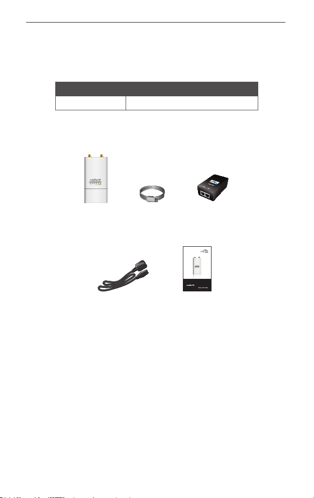
Package Contents
Rocket M5 Metal Strap 24V PoE Adapter
Carrier Class
™
BaseStation
AirMAX
Power Cord Quick Start Guide
Installation Requirements
• Antenna needs to have clear line of sight to the sky.
• Shielded Category 5 (or above) cabling should be used for all
wired Ethernet connections and should be grounded through
the AC ground of the PoE.
We recommend that you protect your networks from the
most brutal environments and devastating ESD attacks
with industrial-grade shielded Ethernet cable from Ubiquiti
Networks. For more details, visit www.ubnt.com/toughcable
1
Page 4
Rocket™ M5
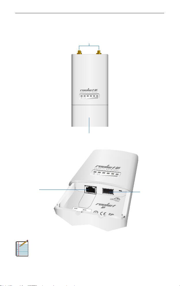
Hardware Overview
Antenna
Connectors
Removable Cover
Ethernet Port
2
USB Port
Note: The USB port is reserved for future use.
Page 5
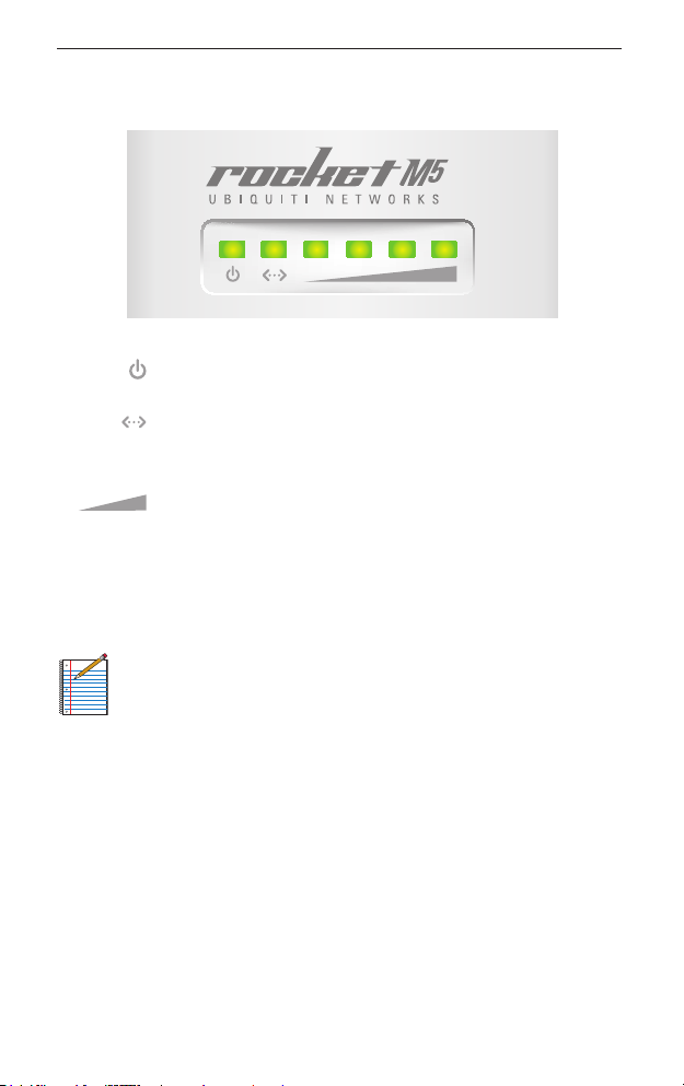
LEDs
Hardware Overview
Power The Power LED will light steady green when
the Rocket M5 is connected to a power source.
Ethernet The Ethernet LED will light steady green
when an active Ethernet connection is made to the
Ethernet port and flash when there is activity.
Signal The first Signal LED is lit when the wireless
signal strength is above -94 dBm, the second LED
when the wireless signal strength is above -80 dBm,
the third LED when the wireless signal strength
is above -73 dBm, and the fourth LED when the
wireless signal strength is above -65 dBm.
Note: By default, the Signal LEDs represent the wireless
signal strength with default threshold values. In the airOS
interface, you can modify the threshold values for each LED.
The settings can be configured on the Advanced tab under
Signal LED Thresholds.
3
Page 6
Rocket™ M5
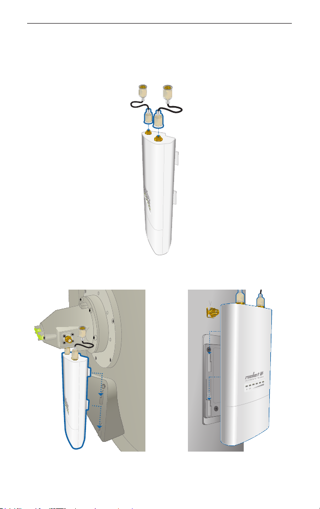
Connecting the Rocket M5
1. Connect the RF cables to the connectors labeled Chain 0 and
Chain 1 on the Rocket M5.
2. Slide the Rocket M5 on to the antenna mount.
Mounting on a Dish Antenna Mounting on a Sector Antenna
4
Page 7

Connecting the Rocket M5
3. Attach the RF cables from the Rocket M5 to the connectors on
the antenna.
Connecting to a Dish Antenna Connecting to a Sector Antenna
5
Page 8

Rocket™ M5
Connecting Power over Ethernet
1. Remove the port cover by lifting the release latch on the
bottom of the Rocket M5 and sliding the cover off.
2. Connect an Ethernet cable to the Ethernet port and to the
Ethernet port labeled POE on the PoE Adapter.
6
Page 9

Connecting Power over Ethernet
3. Connect an Ethernet cable from your LAN to the Ethernet port
labeled LAN on the PoE Adapter.
4. Connect the power cord to the power port on the PoE Adapter.
Connect the other end of the power cord to a power outlet.
5. Replace the port cover.
7
Page 10

Rocket™ M5
airOS Confirmation
Verify connectivity in the airOS interface.
1. Make sure that your host machine is connected via Ethernet to
the Rocket M5.
2. Configure the Ethernet adapter on your host system with a
static IP address on the 192.168.1.x subnet.
3. Launch your Web browser and type http://192.168.1.20 in the
address field. Press enter (PC) or return (Mac).
4. The login screen will appear. Enter ubnt in the Username and
Password fields. Select your Country and Language. You must
agree to the Terms of Use to use the product. Click Login.
Note: U.S. product versions are locked to the U.S. Country
Code to ensure compliance with FCC regulations.
The airOS Interface will appear, allowing you to customize your
settings as needed.
Installer Compliance Responsibility
Devices must be professionally installed and it is the professional
installer's responsibility to make sure the device is operated within
local country regulatory requirements.
8
Page 11

Specifications
Since Ubiquiti Networks equipment can be paired with a variety
of antennas and cables, the Antenna Gain, Cable Loss, and Output
Power fields are provided to the professional installer to assist in
meeting regulatory requirements.
Specifications
RocketM5Specications
Dimensions 16 x 8 x 3 cm
Weight 0.5 kg
Ports (1) 10/100 Ethernet Port
RF Connectors (2) RPSMA (Waterproof)
Enclosure Outdoor UV Stabilized Plastic
Max Power Consumption 6.5 Watts
Power Supply 24V, 1A PoE Supply Included
Power Method Passive PoE (Pairs 4, 5+; 7,8 return)
Operating Temperature -30 to 75° C
Operating Humidity 5 to 95% Condensing
Shock and Vibrations ETSI300-019-1.4
Operating Frequency 5.25 - 5.6 GHz and 5.65 - 5.85 GHz
(-22 to 167° F)
9
Page 12

Rocket™ M5
Safety Notices
1. Read, follow, and keep these instructions.
2. Heed all warnings.
3. Only use attachments/accessories specified by the
manufacturer.
WARNING: Do not use this product in location that can be
submerged by water.
WARNING: Avoid using this product during an electrical
storm. There may be a remote risk of electric shock from
lightning.
Electrical Safety Information
1. Compliance is required with respect to voltage, frequency, and
current requirements indicated on the manufacturer’s label.
Connection to a different power source than those specified
may result in improper operation, damage to the equipment or
pose a fire hazard if the limitations are not followed.
2. There are no operator serviceable parts inside this equipment.
Service should be provided only by a qualified service
technician.
3. This equipment is provided with a detachable power cord
which has an integral safety ground wire intended for
connection to a grounded safety outlet.
a. Do not substitute the power cord with one that is not the
provided approved type. Never use an adapter plug to
connect to a 2-wire outlet as this will defeat the continuity
of the grounding wire.
b. The equipment requires the use of the ground wire as a
part of the safety certification, modification or misuse can
provide a shock hazard that can result in serious injury or
death.
c. Contact a qualified electrician or the manufacturer if there
are questions about the installation prior to connecting the
equipment.
10
Page 13

General Warranty
General Warranty
UBIQUITI NETWORKS, Inc (“UBIQUITI NETWORKS”) represents and
warrants that the Products furnished hereunder shall be free from defects
in material and workmanship for a period of one (1) year from the date
of shipment by UBIQUITI NETWORKS under normal use and operation.
UBIQUITI NETWORKS sole and exclusive obligation under the foregoing
warranty shall be to repair or replace, at its option, any defective Product
that fails during the warranty period. The expense of removal and
reinstallation of any item is not included in this warranty.
The foregoing warranty is exclusive and in lieu of all other warranties,
express or implied, including the implied warranties of merchantability
and fitness for a particular purpose and any warranties arising from a
course of dealing, usage or trade practice with respect to the products.
Repair or replacement in the manner provided herein shall be the sole
and exclusive remedy of Buyer for breach of warranty and shall constitute
fulfillment of all liabilities of UBIQUITI NETWORKS with respect to the
quality and performance of the Products. UBIQUITI NETWORKS reserves
the right to inspect all defective Products (which must be returned by
Buyer to UBIQUITI NETWORKS factory freight prepaid).
No Products will be accepted for replacement or repair without obtaining
a Return Materials Authorization (RMA) number from UBIQUITI NETWORKS.
Products returned without an RMA number will not be processed and will
be returned to Buyer freight collect. UBIQUITI NETWORKS shall have no
obligation to make repairs or replacement necessitated by catastrophe,
fault, negligence, misuse, abuse, or accident by Buyer, Buyer’s customers or
any other parties. The warranty period of any repaired or replaced. Product
shall not extend beyond its original term.
Warranty Conditions
The foregoing warranty shall apply only if:
(I) The Product has not been subjected to misuse, neglect or unusual
physical, electrical or electromagnetic stress, or some other type of
accident.
(II) No modification, alteration or addition has been made to the Product
by persons other than UBIQUITI NETWORKS or UBIQUITI NETWORK’S
authorized representatives or otherwise approved by UBIQUITI
NETWORKS.
(III) The Product has been properly installed and used at all times in
accordance, and in all material respects, with the applicable Product
documentation.
(IV) All Ethernet cabling runs use CAT5 (or above) shielded cabling.
Disclaimer: UBIQUITI NETWORKS does not warrant that the operation of
the products is error-free or that operation will be uninterrupted. In no
event shall UBIQUITI NETWORKS be responsible for damages or claims
of any nature or description relating to system performance, including
coverage, buyer’s selection of products for buyer’s application and/or
failure of products to meet government or regulatory requirements.
11
Page 14

Rocket™ M5
Returns
In the unlikely event a defect occurs, please work through the dealer or
distributor from which this product was purchased.
Compliance
FCC
Changes or modifications not expressly approved by the party responsible
for compliance could void the user’s authority to operate the equipment.
This device complies with Part 15 of the FCC Rules. Operation is subject to
the following two conditions:
1. This device may not cause interference, and
2. This device must accept any interference, including interference that
may cause undesired operation of the device.
NOTE: This equipment has been tested and found to comply with the
limits for a Class A digital device, pursuant to part 15 of the FCC Rules.
These limits are designed to provide reasonable protection against
harmful interference when the equipment is operated in a commercial
environment. This equipment generates, uses, and can radiate radio
frequency energy and, if not installed and used in accordance with
the instruction manual, may cause harmful interference to radio
communications. Operations of this equipment in a residential area is likely
to cause harmful interference in which case the user will be required to
correct the interference at his own expense.
For MPE and antenna usage details, please visit our website at
www.ubnt.com/compliance
RF Exposure Warning
The transceiver described here emits radio frequency energy. Although
the power level is low, the concentrated energy from a directional antenna
may pose a health hazard. Do not allow people to come closer than
37.2cmtotheantennawhenthetransmitterisoperating.
Additional information on RF exposure is available on the Internet at
www.fcc.gov/oet/info/documents/bulletins
L'émetteur-récepteur décrit ici émet de l'énergie de fréquence radio.
Bien que le niveau de puissance est faible, l'énergie concentrée à partir
d'une antenne directionnelle peut présenter un danger pour la santé. Ne
paspermettreauxgensdeserapprocherde37.2cmàl'antennelorsque
l'émetteur est en marche.
Des renseignements supplémentaires sur l'exposition aux RF est
disponible sur Internet à www.fcc.gov/oet/info/documents/bulletins
12
Page 15

Compliance
CE Marking
CE marking on this product represents the product is in compliance with
all directives that are applicable to it.
Alert sign! Follows CE marking
Alert sign must be indicated if a restriction on use applied to the product
and it must follow the CE marking.
NB-Identification number (if there is any)
Notified body number is indicated if it is involved in the conformity
assessment procedure.
Please check the CE mark on the product label to find out which notified
body was involved during assessment.
RoHS/WEEE Compliance Statement
English
European Directive 2002/96/EC requires that the equipment bearing this symbol on
the product and/or its packaging must not be disposed of with unsorted municipal
waste. The symbol indicates that this product should be disposed of separately from
regular household waste streams. It is your responsibility to dispose of this and other
electric and electronic equipment via designated collection facilities appointed by
the government or local authorities. Correct disposal and recycling will help prevent
potential negative consequences to the environment and human health. For more
detailed information about the disposal of your old equipment, please contact
your local authorities, waste disposal service, or the shop where you purchased the
product.
13
Page 16

Rocket™ M5
Deutsch
Die Europäische Richtlinie 2002/96/EC verlangt, dass technische Ausrüstung, die
direkt am Gerät und/oder an der Verpackung mit diesem Symbol versehen ist,
nicht zusammen mit unsortiertem Gemeindeabfall entsorgt werden darf. Das
Symbol weist darauf hin, dass das Produkt von regulärem Haushaltmüll getrennt
entsorgt werden sollte. Es liegt in Ihrer Verantwortung, dieses Gerät und andere
elektrische und elektronische Geräte über die dafür zuständigen und von der
Regierung oder örtlichen Behörden dazu bestimmten Sammelstellen zu entsorgen.
Ordnungsgemäßes Entsorgen und Recyceln trägt dazu bei, potentielle negative
Folgen für Umwelt und die menschliche Gesundheit zu vermeiden. Wenn Sie weitere
Informationen zur Entsorgung Ihrer Altgeräte benötigen, wenden Sie sich bitte an die
örtlichen Behörden oder städtischen Entsorgungsdienste oder an den Händler, bei
dem Sie das Produkt erworben haben.
Español
La Directiva 2002/96/CE de la UE exige que los equipos que lleven este símbolo en
el propio aparato y/o en su embalaje no deben eliminarse junto con otros residuos
urbanos no seleccionados. El símbolo indica que el producto en cuestión debe
separarse de los residuos domésticos convencionales con vistas a su eliminación.
Es responsabilidad suya desechar este y cualesquiera otros aparatos eléctricos
y electrónicos a través de los puntos de recogida que ponen a su disposición el
gobierno y las autoridades locales. Al desechar y reciclar correctamente estos
aparatos estará contribuyendo a evitar posibles consecuencias negativas para
el medio ambiente y la salud de las personas. Si desea obtener información más
detallada sobre la eliminación segura de su aparato usado, consulte a las autoridades
locales, al servicio de recogida y eliminación de residuos de su zona o pregunte en la
tienda donde adquirió el producto.
Français
La directive européenne 2002/96/CE exige que l’équipement sur lequel est apposé
ce symbole sur le produit et/ou son emballage ne soit pas jeté avec les autres ordures
ménagères. Ce symbole indique que le produit doit être éliminé dans un circuit
distinct de celui pour les déchets des ménages. Il est de votre responsabilité de jeter
ce matériel ainsi que tout autre matériel électrique ou électronique par les moyens
de collecte indiqués par le gouvernement et les pouvoirs publics des collectivités
territoriales. L’élimination et le recyclage en bonne et due forme ont pour but de
lutter contre l’impact néfaste potentiel de ce type de produits sur l’environnement et
la santé publique. Pour plus d’informations sur le mode d’élimination de votre ancien
équipement, veuillez prendre contact avec les pouvoirs publics locaux, le service de
traitement des déchets, ou l’endroit où vous avez acheté le produit.
Italiano
La direttiva europea 2002/96/EC richiede che le apparecchiature contrassegnate
con questo simbolo sul prodotto e/o sull’imballaggio non siano smaltite insieme
ai rifiuti urbani non differenziati. Il simbolo indica che questo prodotto non deve
essere smaltito insieme ai normali rifiuti domestici. È responsabilità del proprietario
smaltire sia questi prodotti sia le altre apparecchiature elettriche ed elettroniche
mediante le specifiche strutture di raccolta indicate dal governo o dagli enti
pubblici locali. Il corretto smaltimento ed il riciclaggio aiuteranno a prevenire
conseguenze potenzialmente negative per l’ambiente e per la salute dell’essere
umano. Per ricevere informazioni più dettagliate circa lo smaltimento delle vecchie
apparecchiature in Vostro possesso, Vi invitiamo a contattare gli enti pubblici di
competenza, il servizio di smaltimento rifiuti o il negozio nel quale avete acquistato il
prodotto.
14
Page 17

Declaration of Conformity
Declaration of Conformity
Česky
[Czech]
Dansk
[Danish]
Nederlands
[Dutch]
English
Eesti
[Estonian]
Suomi
[Finnish]
Français
[French]
Deutsch
[German]
Ελληνική
[Greek]
UBIQUITI NETWORKS tímto prohla uje, e tento UBIQUITI
NETWORKS device, je ve shod se základními po adavky a dal ími p
íslu n mi ustanoveními sm rnice 1999/5/ES.
Undertegnede UBIQUITI NETWORKS erklærer herved, at følgende
udstyr UBIQUITI NETWORKS device, overholder de væsentlige krav
og øvrige relevante krav i direktiv 1999/5/EF.
Hierbij verklaart UBIQUITI NETWORKS dat het toestel UBIQUITI
NETWORKS device, in overeenstemming is met de essentiële eisen
en de andere relevante bepalingen van richtlijn 1999/5/EG.
Bij deze verklaart UBIQUITI NETWORKS dat deze UBIQUITI
NETWORKS device, voldoet aan de essentiële eisen en aan de
overige relevante bepalingen van Richtlijn 1999/5/EC.
Hereby, UBIQUITI NETWORKS, declares that this UBIQUITI
NETWORKS device, is in compliance with the essential
requirements and other relevant provisions of Directive 1999/5/EC.
Käesolevaga kinnitab UBIQUITI NETWORKS seadme UBIQUITI
NETWORKS device, vastavust direktiivi 1999/5/EÜ põhinõuetele ja
nimetatud direktiivist tulenevatele teistele asjakohastele sätetele.
UBIQUITI NETWORKS vakuuttaa täten että UBIQUITI NETWORKS
device, tyyppinen laite on direktiivin 1999/5/EY oleellisten
vaatimusten ja sitä koskevien direktiivin muiden ehtojen
mukainen.
Par la présente UBIQUITI NETWORKS déclare que l’appareil
UBIQUITI NETWORKS, device est conforme aux exigences
essentielles et aux autres dispositions pertinentes de la directive
1999/5/CE.
Par la présente, UBIQUITI NETWORKS déclare que ce UBIQUITI
NETWORKS device, est conforme aux exigences essentielles et
aux autres dispositions de la directive 1999/5/CE qui lui sont
applicables.
Hiermit erklärt UBIQUITI NETWORKS, dass sich diese UBIQUITI
NETWORKS device, in Übereinstimmung mit den grundlegenden
Anforderungen und den anderen relevanten Vorschriften der
Richtlinie 1999/5/EG befindet”. (BMWi)
Hiermit erklärt UBIQUITI NETWORKS die Übereinstimmung des
Gerätes UBIQUITI NETWORKS device, mit den grundlegenden
Anforderungen und den anderen relevanten Festlegungen der
Richtlinie 1999/5/EG. (Wien)
ΜΕ ΤΗΝ ΠΑΡΟΥΣΑ UBIQUITI NETWORKS ΔΗΛΩΝΕΙ ΟΤΙ UBIQUITI
NETWORKS device, ΣΥΜΜΟΡΦΩΝΕΤΑΙ ΠΡΟΣ ΤΙΣ ΟΥΣΙΩΔΕΙΣ
ΑΠΑΙΤΗΣΕΙΣ ΚΑΙ ΤΙΣ ΛΟΙΠΕΣ ΣΧΕΤΙΚΕΣ ΔΙΑΤΑΞΕΙΣ ΤΗΣ ΟΔΗΓΙΑΣ
1995/5/ΕΚ.
15
Page 18

Rocket™ M5
Magyar
[Hungarian]
Íslenska
[Icelandic]
Italiano
[Italian]
Latviski
[Latvian]
Lietuviškai
[Lithuanian]
Malti
[Maltese]
Norsk
[Norwegian]
Slovensky
[Slovak]
Svenska
[Swedish]
Español
[Spanish]
Polski
[Polish]
Português
[Portuguese]
Română
[Romanian]
Alulírott, UBIQUITI NETWORKS nyilatkozom, hogy a
UBIQUITI NETWORKS device, megfelel a vonatkozó alapvetõ
követelményeknek és az 1999/5/EC irányelv egyéb elõírásainak.
Hér me l sir UBIQUITI NETWORKS yfir ví a UBIQUITI NETWORKS
device, er í samræmi vi grunnkröfur og a rar kröfur, sem ger ar eru í
tilskipun 1999/5/EC.
Con la presente UBIQUITI NETWORKS dichiara che questo
UBIQUITI NETWORKS device, è conforme ai requisiti essenziali ed
alle altre disposizioni pertinenti stabilite dalla direttiva 1999/5/CE.
Ar o UBIQUITI NETWORKS deklar , ka UBIQUITI NETWORKS device,
atbilst Direkt vas 1999/5/EK b tiskaj m pras b m un citiem ar to saist
tajiem noteikumiem.
UBIQUITI NETWORKS deklaruoja, kad šis UBIQUITI NETWORKS
įrenginys atitinka esminius reikalavimus ir kitas 1999/5/EB
Direktyvos nuostatas.
Hawnhekk, UBIQUITI NETWORKS, jiddikjara li dan UBIQUITI
NETWORKS device, jikkonforma mal- ti ijiet essenzjali u ma
provvedimenti o rajn relevanti li hemm fid-Dirrettiva 1999/5/EC.
UBIQUITI NETWORKS erklærer herved at utstyret UBIQUITI
NETWORKS device, er i samsvar med de grunnleggende krav og
øvrige relevante krav i direktiv 1999/5/EF.
UBIQUITI NETWORKS t mto vyhlasuje, e UBIQUITI NETWORKS
device, sp a základné po iadavky a v etky príslu né ustanovenia
Smernice 1999/5/ES.
Härmed intygar UBIQUITI NETWORKS att denna UBIQUITI
NETWORKS device, står I överensstämmelse med de väsentliga
egenskapskrav och övriga relevanta bestämmelser som framgår
av direktiv 1999/5/EG.
Por medio de la presente UBIQUITI NETWORKS declara que el
UBIQUITI NETWORKS device, cumple con los requisitos esenciales
y cualesquiera otras disposiciones aplicables o exigibles de la
Directiva 1999/5/CE.
Niniejszym, firma UBIQUITI NETWORKS o wiadcza, e produkt serii
UBIQUITI NETWORKS device, spełnia zasadnicze wymagania i inne
istotne postanowienia Dyrektywy 1999/5/EC.
UBIQUITI NETWORKS declara que este UBIQUITI NETWORKS
device, está conforme com os requisitos essenciais e outras
disposições da Directiva 1999/5/CE.
Prin prezenta, declarăm că acest produs este în conformitate cu
cerinţele esenţiale şi cu alte prevederi relevante din Directiva
1999/5/CE.
16
JL122311
Page 19

Page 20

Ubiquiti Networks Support
Email: support@ubnt.com
Phone (9 a.m. - 5 p.m. PST): 408-942-1153
Online Resources
Wiki Page: www.ubnt.com/wiki
Support Forum: www.ubnt.com/forum
Downloads: www.ubnt.com/support/downloads
www.ubnt.com
© 2011 Ubiquiti Networks, Inc. All rights reserved.
 Loading...