

Page 1

Carrier Class
AirMax BaseStation
Page 2

Page 3
Introduction
Introduction
Thank you for purchasing the PowerBridge M5 X3. This is a pointto-point CPE wireless device.
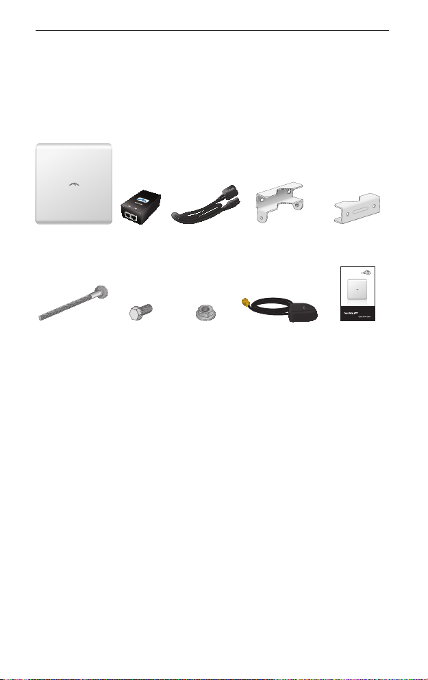
Package Contents
PowerBridge
M5 X3
M8X135
Carriage Bolts
(Qty. 4)
48V PoE
Adapter
Serrated
Flange Bolts
(Qty. 4)
Power Cord Antenna Bracket
Serrated
Flange Lock
Nuts (Qty. 4)
Clamps (Qty. 2)
GPS Patch
Antenna
Pole Bracket
Clamps (Qty. 2)
Carrier Class
AirMax BaseStation
Quick Start
Guide
Installation Requirements
• Adjustable wrench or one 16 mm and one 24 mm wrench
• Flathead screwdriver
• Shielded Category 5 (or above) cabling should be used for all
wired Ethernet connections and should be grounded through
the AC ground of the PoE.
We recommend that you protect your networks from the
most brutal environments and devastating ESD attacks
with industrial-grade shielded Ethernet cable from Ubiquiti
Networks. For more details, visit www.ubnt.com/toughcable
1
Page 4
PowerBridge M5 X3
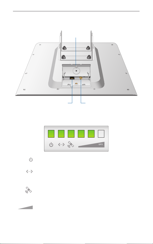
Hardware Overview
Cover
LEDs
2
Ethernet Port
Connects to GPS
Patch Antenna
Power The Power LED will light steady green when
the PowerBridge is connected to a power source.
Ethernet The Ethernet LED will light steady green
when an active Ethernet connection is made and
flash when there is activity.
GPS The GPS LED lights up green when the GPS
signal strength can sustain AirSync operation. This
requires a minimum of 3 satellite connections.
Signal The first Signal LED is lit when the wireless
signal strength is above -94 dBm, the second LED
when the wireless signal strength is above -77 dBm,
and the third LED when the wireless signal signal
strength is above -65 dBm.
Page 5
Hardware Installation
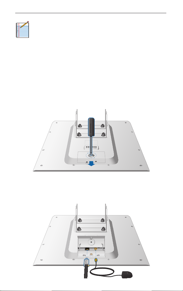
Note: By default, the Signal LEDs represent the wireless
signal strength with default threshold values. In the airOS
interface, you can modify the threshold values for each
LED or configure the LEDs to display the GPS connection
quality instead. The settings can be configured on the
Advanced tab under Signal LED Thresholds.
Hardware Installation
To install the PowerBridge M5 X3, perform the following steps:
1. Use a flathead screwdriver to unlock the cover. Turn the screw
counter-clockwise until it is loose. The screw remains attached
to the cover. Lift the cover by pressing down and raising it up.
2. Connect an Ethernet cable and the GPS Patch Antenna. There
are grooves for the cables on the cover. Align them properly
and slide the cover back on and secure it with the screw.
3
Page 6

PowerBridge M5 X3
3. Insert the M8X135 Carriage Bolts into the Antenna Bracket
Clamps.
4. Connect the Antenna Bracket Clamps to the PowerBridge using
the four Serrated Flange Bolts.
4
Page 7

Hardware Installation
5. Mount the PowerBridge to the pole by performing the
following steps:
a. Position the PowerBridge in the desired mounting location
on the pole.
b. Slide the Pole Bracket Clamps on to the Carriage Bolts.
c. Use the four Serrated Flange Lock Nuts to secure the
PowerBridge to the pole.
6. Adjust the operating angle of the PowerBridge by adjusting the
Serrated Flange Bolts on the top Antenna Bracket Clamp.
5
Page 8

PowerBridge M5 X3
7. Connect the other end of the Ethernet cable from the
PowerBridge to the Ethernet port labeled POE on the PoE
Adapter.
8. Connect an Ethernet cable from your LAN to the Ethernet port
labeled LAN on the PoE Adapter.
6
Page 9

Hardware Installation
9. Connect the power cord to the power port on the PoE Adapter.
Connect the other end of the power cord to a power outlet.
10. Place the GPS Patch Antenna on the mounting hardware.
7
Page 10

PowerBridge M5 X3
Accessing the AirOS Utility
1. Make sure that your host machine is connected to the LAN that
is connected to the PowerBridge.
2. Configure the Ethernet adapter on your host system with a
static IP address on the 192.168.1.x subnet (e.g. 192.168.1.100).
3. Launch your Web browser and type http://192.168.1.20 in the
address field and press enter (PC) or return (Mac).
4. The login screen will appear. Enter ubnt in the Username and
Password fields. Select your Country and Language. You must
agree to the Terms of Use to use the product. Click Login.
Note: U.S. product versions are locked to the U.S. Country
Code to ensure compliance with FCC regulations.
The AirOS Interface will appear allowing you to customize your
settings as needed.
Installer Compliance Responsibility
Devices must be professionally installed and it is the professional
installer's responsibility to make sure the device is operated within
local country regulatory requirements.
8
Page 11

Specifications
Specifications
Enclosure Size 445 x 416 x 34 mm
Weight 3.82 kg
Max Power Consumption 8 Watts
Power Supply 48V, 0.5A surge protection
integrated PoE adapter included
Power Method Passive PoE (Pairs 4, 5+; 7,8 return)
Operating Temperature -30 to 80° C
Operating Humidity 5 to 95% Condensing
Operating Frequency
Device Supports 5170 - 5875 MHz
USA/Canada Supports* 5745 - 5850 MHz
Networking Interface (1) 10/100/1000 Ethernet Port
* Products shipped in the USA/Canada are locked to the US Country Code to
ensure compliance with FCC regulations.
9
Page 12

PowerBridge M5 X3
Safety Notices
1. Read, follow, and keep these instructions.
2. Heed all warnings.
3. Only use attachments/accessories specified by the
manufacturer.
WARNING: Do not use this product in location that can
be submerged by water.
WARNING: Avoid using this product during an electrical
storm. There may be a remote risk of electric shock from
lightning.
Electrical Safety Information
1. Compliance is required with respect to voltage, frequency, and
current requirements indicated on the manufacturer’s label.
Connection to a different power source than those specified
may result in improper operation, damage to the equipment or
pose a fire hazard if the limitations are not followed.
2. There are no operator serviceable parts inside this equipment.
Service should be provided only by a qualified service technician.
3. This equipment is provided with a detachable power cord which
has an integral safety ground wire intended for connection to a
grounded safety outlet.
a. Do not substitute the power cord with one that is not the
provided approved type. Never use an adapter plug to
connect to a 2-wire outlet as this will defeat the continuity of
the grounding wire.
b. The equipment requires the use of the ground wire as a part
of the safety certification, modification or misuse can provide
a shock hazard that can result in serious injury or death.
c. Contact a qualified electrician or the manufacturer if there
are questions about the installation prior to connecting the
equipment.
d. Protective earthing is provided by Listed AC adapter. Building
installation shall provide appropriate short-circuit backup
protection.
e. Protective bonding must be installed in accordance with
local national wiring rules and regulations.
10
Page 13

General Warranty
General Warranty
UBIQUITI NETWORKS, Inc (“UBIQUITI NETWORKS”) represents
and warrants that the Products furnished hereunder shall be free
from defects in material and workmanship for a period of one (1)
year from the date of shipment by UBIQUITI NETWORKS under
normal use and operation. UBIQUITI NETWORKS sole and exclusive
obligation under the foregoing warranty shall be to repair or
replace, at its option, any defective Product that fails during the
warranty period. The expense of removal and reinstallation of any
item is not included in this warranty.
The foregoing warranty is exclusive and in lieu of all other
warranties, express or implied, including the implied warranties
of merchantability and fitness for a particular purpose and any
warranties arising from a course of dealing, usage or trade practice
with respect to the products. Repair or replacement in the manner
provided herein shall be the sole and exclusive remedy of Buyer
for breach of warranty and shall constitute fulfillment of all
liabilities of UBIQUITI NETWORKS with respect to the quality and
performance of the Products. UBIQUITI NETWORKS reserves the
right to inspect all defective Products (which must be returned by
Buyer to UBIQUITI NETWORKS factory freight prepaid).
No Products will be accepted for replacement or repair without
obtaining a Return Materials Authorization (RMA) number from
UBIQUITI NETWORKS. Products returned without an RMA number
will not be processed and will be returned to Buyer freight collect.
UBIQUITI NETWORKS shall have no obligation to make repairs
or replacement necessitated by catastrophe, fault, negligence,
misuse, abuse, or accident by Buyer, Buyer’s customers or any
other parties. The warranty period of any repaired or replaced.
Product shall not extend beyond its original term.
Warranty Conditions
The foregoing warranty shall apply only if:
(I) The Product has not been subjected to misuse, neglect or unusual
physical, electrical or electromagnetic stress, or some other type
of accident.
11
Page 14

PowerBridge M5 X3
(II) No modification, alteration or addition has been made to
the Product by persons other than UBIQUITI NETWORKS
or UBIQUITI NETWORK’S authorized representatives or
otherwise approved by UBIQUITI NETWORKS.
(III) The Product has been properly installed and used at all times
in accordance, and in all material respects, with the applicable
Product documentation.
(IV) All Ethernet cabling runs use CAT5 (or above) shielded cabling.
Disclaimer: UBIQUITI NETWORKS does not warrant that the
operation of the products is error-free or that operation will
be uninterrupted. In no event shall UBIQUITI NETWORKS be
responsible for damages or claims of any nature or description
relating to system performance, including coverage, buyer’s
selection of products for buyer’s application and/or failure of
products to meet government or regulatory requirements.
Returns
In the unlikely event a defect occurs, please work through the
dealer or distributor from which this product was purchased.
Compliance
FCC
Changes or modifications not expressly approved by Ubiquiti
Networks, Inc. could void the user’s authority to operate the
equipment.
This device complies with Part 15 of the FCC Rules. Operation is
subject to the following two conditions:
1. This device may not cause interference, and
2. This device must accept any interference, including
interference that may cause undesired operation of the device.
NOTE: This equipment has been tested and found to comply
with the limits for a Class A digital device, pursuant to part 15 of
the FCC Rules. These limits are designed to provice reasonable
protection against harmful interference when the equipment
is operated in a commercial environment. This equipment
generates, uses, and can radiate radio frequency energy and, if not
installed and used in accordance with the instruction manual, may
12
Page 15

Compliance
cause harmful interference to radio communications. Operations
of this equipment in a residential area is likely to cause harmful
interference in which case the user will be required to correct the
interference at his own expense.
RF Exposure Warning
The transceiver described here emits radio frequency energy.
Although the power level is low, the concentrated energy from
a directional antenna may pose a health hazard. Do not allow
people to come closer than 157 cm to the antenna when the
transmitter is operating.
Additional information on RF exposure is available on the Internet
at www.fcc.gov/oet/info/documents/bulletins
L'émetteur-récepteur décrit ici émet de l'énergie de fréquence
radio. Bien que le niveau de puissance est faible, l'énergie
concentrée à partir d'une antenne directionnelle peut présenter
un danger pour la santé. Ne pas permettre aux gens de se
rapprocher de 157 cm à l'antenne lorsque l'émetteur est en
marche.
Des renseignements supplémentaires sur l'exposition aux RF est
disponible sur Internet à www.fcc.gov/oet/info/documents/
bulletins
CE Marking
CE marking on this product represents the product is in
compliance with all directives that are applicable to it.
Alert sign! Follows CE marking
Alert sign must be indicated if a restriction on use applied to the
product and it must follow the CE marking.
NB-Identification number (if there is any)
Notified body number is indicated if it is involved in the
conformity assessment procedure.
Please check the CE mark on the product label to find out which notified
body was involved during assessment.
13
Page 16

PowerBridge M5 X3
Declaration of Conformity
Česky
[Czech]
Dansk
[Danish]
Nederlands
[Dutch]
English
Eesti
[Estonian]
Suomi
[Finnish]
Français
[French]
Deutsch
[German]
Ελληνική
[Greek]
Magyar
[Hungarian]
Íslenska
[Icelandic]
Italiano
[Italian]
UBIQUITI NETWORKS tímto prohla uje, e tento UBIQUITI
NETWORKS device, je ve shod se základními po adavky a dal ími p
íslu n mi ustanoveními sm rnice 1999/5/ES.
Undertegnede UBIQUITI NETWORKS erklærer herved, at følgende
udstyr UBIQUITI NETWORKS device, overholder de væsentlige krav
og øvrige relevante krav i direktiv 1999/5/EF.
Hierbij verklaart UBIQUITI NETWORKS dat het toestel UBIQUITI
NETWORKS device, in overeenstemming is met de essentiële eisen
en de andere relevante bepalingen van richtlijn 1999/5/EG.
Bij deze verklaart UBIQUITI NETWORKS dat deze UBIQUITI
NETWORKS device, voldoet aan de essentiële eisen en aan de
overige relevante bepalingen van Richtlijn 1999/5/EC.
Hereby, UBIQUITI NETWORKS, declares that this UBIQUITI
NETWORKS device, is in compliance with the essential
requirements and other relevant provisions of Directive 1999/5/EC.
Käesolevaga kinnitab UBIQUITI NETWORKS seadme UBIQUITI
NETWORKS device, vastavust direktiivi 1999/5/EÜ põhinõuetele ja
nimetatud direktiivist tulenevatele teistele asjakohastele sätetele.
UBIQUITI NETWORKS vakuuttaa täten että UBIQUITI NETWORKS
device, tyyppinen laite on direktiivin 1999/5/EY oleellisten
vaatimusten ja sitä koskevien direktiivin muiden ehtojen
mukainen.
Par la présente UBIQUITI NETWORKS déclare que l’appareil
UBIQUITI NETWORKS, device est conforme aux exigences
essentielles et aux autres dispositions pertinentes de la directive
1999/5/CE.
Hiermit erklärt UBIQUITI NETWORKS, dass sich diese UBIQUITI
NETWORKS device, in Übereinstimmung mit den grundlegenden
Anforderungen und den anderen relevanten Vorschriften der
Richtlinie 1999/5/EG befindet”. (BMWi)
ΜΕ ΤΗΝ ΠΑΡΟΥΣΑ UBIQUITI NETWORKS ΔΗΛΩΝΕΙ ΟΤΙ UBIQUITI
NETWORKS device, ΣΥΜΜΟΡΦΩΝΕΤΑΙ ΠΡΟΣ ΤΙΣ ΟΥΣΙΩΔΕΙΣ
ΑΠΑΙΤΗΣΕΙΣ ΚΑΙ ΤΙΣ ΛΟΙΠΕΣ ΣΧΕΤΙΚΕΣ ΔΙΑΤΑΞΕΙΣ ΤΗΣ ΟΔΗΓΙΑΣ
1995/5/ΕΚ.
Alulírott, UBIQUITI NETWORKS nyilatkozom, hogy a
UBIQUITI NETWORKS device, megfelel a vonatkozó alapvetõ
követelményeknek és az 1999/5/EC irányelv egyéb elõírásainak.
Hér me l sir UBIQUITI NETWORKS yfir ví a UBIQUITI NETWORKS
device, er í samræmi vi grunnkröfur og a rar kröfur, sem ger ar eru í
tilskipun 1999/5/EC.
Con la presente UBIQUITI NETWORKS dichiara che questo UBIQUITI
NETWORKS device, è conforme ai requisiti essenziali ed alle altre
disposizioni pertinenti stabilite dalla direttiva 1999/5/CE.
14
Page 17

Declaration of Conformity
Latviski
[Latvian]
Lietuviškai
[Lithuanian]
Malti
[Maltese]
Norsk
[Norwegian]
Slovensky
[Slovak]
Svenska
[Swedish]
Español
[Spanish]
Polski
[Polish]
Português
[Portuguese]
Ar o UBIQUITI NETWORKS deklar , ka UBIQUITI NETWORKS device,
atbilst Direkt vas 1999/5/EK b tiskaj m pras b m un citiem ar to saist
tajiem noteikumiem.
UBIQUITI NETWORKS deklaruoja, kad šis UBIQUITI NETWORKS
įrenginys atitinka esminius reikalavimus ir kitas 1999/5/EB
Direktyvos nuostatas.
Hawnhekk, UBIQUITI NETWORKS, jiddikjara li dan UBIQUITI
NETWORKS device, jikkonforma mal- ti ijiet essenzjali u ma
provvedimenti o rajn relevanti li hemm fid-Dirrettiva 1999/5/EC.
UBIQUITI NETWORKS erklærer herved at utstyret UBIQUITI
NETWORKS device, er i samsvar med de grunnleggende krav og
øvrige relevante krav i direktiv 1999/5/EF.
UBIQUITI NETWORKS t mto vyhlasuje, e UBIQUITI NETWORKS
device, sp a základné po iadavky a v etky príslu né ustanovenia
Smernice 1999/5/ES.
Härmed intygar UBIQUITI NETWORKS att denna UBIQUITI
NETWORKS device, står I överensstämmelse med de väsentliga
egenskapskrav och övriga relevanta bestämmelser som framgår av
direktiv 1999/5/EG.
Por medio de la presente UBIQUITI NETWORKS declara que el
UBIQUITI NETWORKS device, cumple con los requisitos esenciales
y cualesquiera otras disposiciones aplicables o exigibles de la
Directiva 1999/5/CE.
Niniejszym, firma UBIQUITI NETWORKS o wiadcza, e produkt serii
UBIQUITI NETWORKS device, spełnia zasadnicze wymagania i inne
istotne postanowienia Dyrektywy 1999/5/EC.
UBIQUITI NETWORKS declara que este UBIQUITI NETWORKS device,
está conforme com os requisitos essenciais e outras disposições da
Directiva 1999/5/CE.
15
Page 18

English
We recommend that you protect your networks
from the most brutal environments and
devastating ESD attacks with industrial-grade
shielded Ethernet cable from Ubiquiti Networks.
For more details, visit www.ubnt.com/toughcable
Deutsch
Schützen Sie Ihre Netzwerke vor extremen Umwelteinflüssen
und verheerender elektrostatischer Entladung (ESD), indem
Sie abgeschirmte Ethernetkabel in Unternehmensqualität von
Ubiquiti Networks verwenden. Weitere Informationen erhalten Sie
unter www.ubnt.com/toughcable
Español
Le recomendamos que proteja sus redes de los entornos más
hostiles y los devastadores efectos de las descargas electrostáticas
utilizando cable Ethernet blindado con calidad-industrial de
Ubiquiti Networks. Para obtener más información, visite
www.ubnt.com/toughcable
Français
Nous vous recommandons de protéger vos réseaux contre les
environnements les plus brutaux et les décharges électrostatiques
les plus dévastatrices avec un câble Ethernet Ubiquiti Networks
avec blindage renforcé. Pour en savoir plus, rendez-vous sur
www.ubnt.com/toughcable
Italiano
Si consiglia di proteggere le reti dagli ambienti e dagli attacchi
ESD più invasivi con il cavo Ethernet schermato-di tipo industriale
di Ubiquiti Networks. Per ulteriori informazioni, visitare il sito Web
www.ubnt.com/toughcable
RR071811
Page 19

Page 20

Ubiquiti Networks Support
Email: support@ubnt.com
Phone (9 a.m. - 5 p.m. PST): 408-942-1153
Online Resources
Wiki Page: www.ubnt.com/wiki
Support Forum: www.ubnt.com/forum
Knowledge Base: www.ubnt.com/kb
Downloads: www.ubnt.com/support/downloads
www.ubnt.com
© 2011 Ubiquiti Networks, Inc. All rights reserved.
 Loading...