

Ubiquiti M5GHP User Manual
M5GHP
5 GHz High-Performance
Model:

Introduction
Introduction
Thank you for purchasing the Ubiquiti Networks™ airGrid™
5GHz High-Performance Integrated InnerFeed Antenna, model
AGM5-HP-1724. This Quick Start Guide is designed to guide you
through the installation, and show you how to access the airOS™
Configuration Interface.
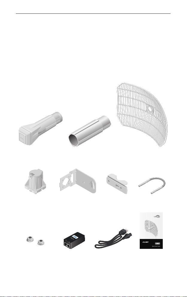
Package Contents
Antenna Feed Feed Extender Grid Reflector
Rear Housing L-Bracket Pole Clamp M8 U-Bolt
5 GHz High-Performance
Integrated InnerFeed
Antenna
Model: AGM5-HP-1724
M8 Flange Nuts
(Qty. 2)
PoE Adapter
(24V, 0.5A)
Power Cord Quick Start Guide
Grid reflector and mounting hardware packaged separately. Products may be
different from pictures and are subject to change without notice.
1
™
airGrid
AGM5-HP-1724 Quick Start Guide
Installation Requirements
• 13 mm or ½" wrench
• Shielded Category 5 (or above) cabling should be used for all
wired Ethernet connections and should be grounded through
the AC ground of the PoE.
We recommend that you protect your networks from the
most brutal environments and devastating ESD attacks
with industrial-grade shielded Ethernet cable from Ubiquiti
Networks. For more details, visit www.ubnt.com/toughcable
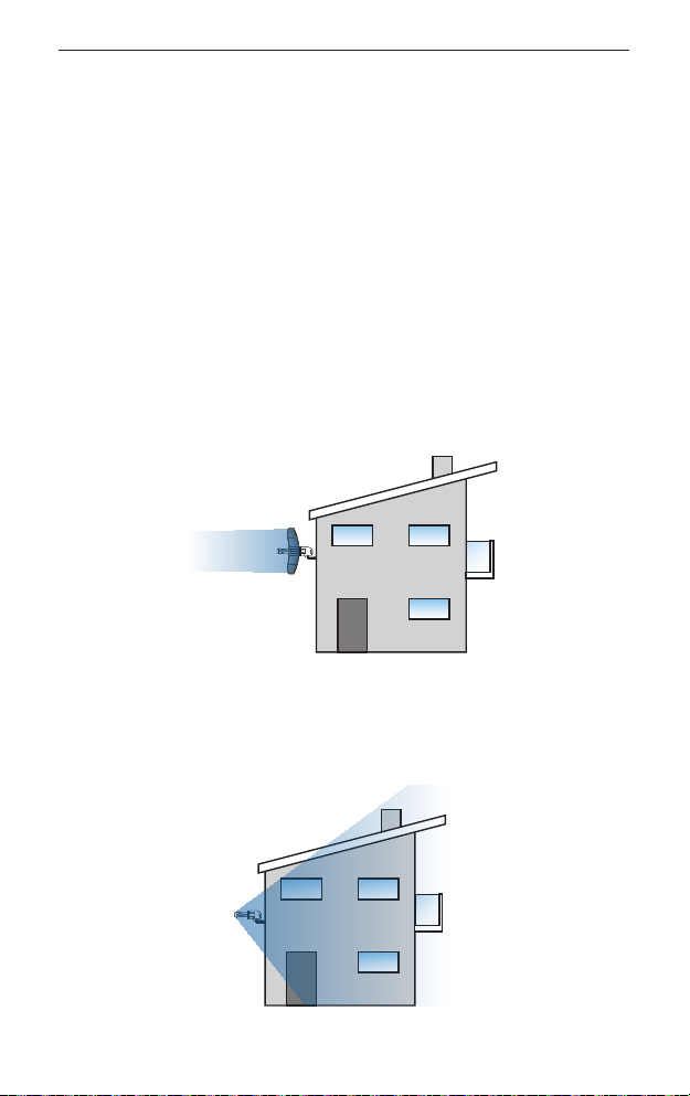
Application Examples
The airGrid mounted outdoors with the Grid Reflector installed
provides directional outdoor coverage (gain reflector-dependent).
The airGrid mounted outdoors without the Grid Reflector installed
provides outdoor-to-indoor coverage using the 3 dBi Antenna Feed
only.
2
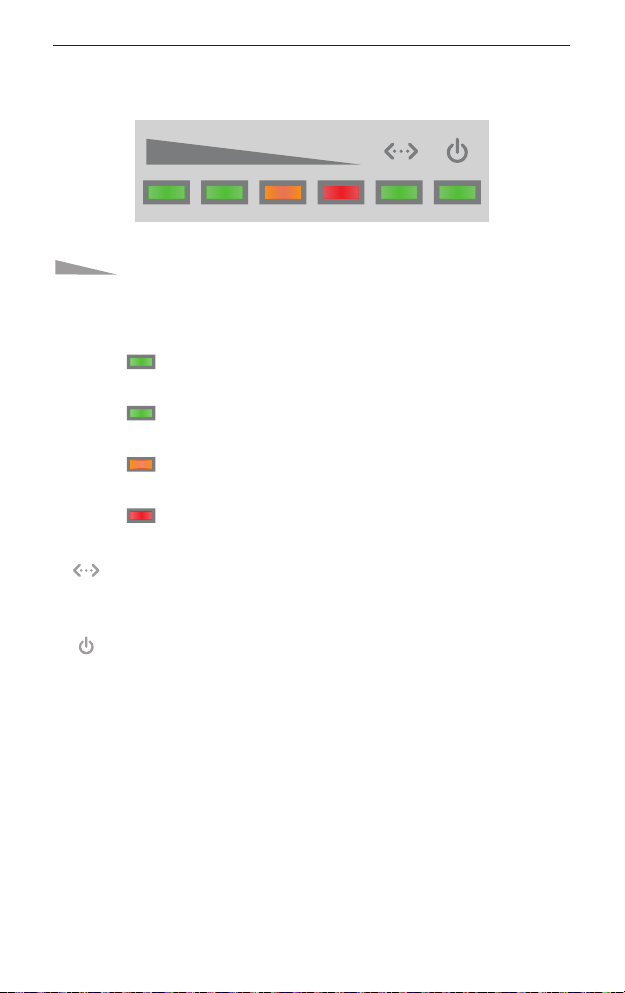
LEDs
LEDs
Signal In airOS, you can modify the wireless signal
strength threshold values for each LED on the
Advanced tab under Signal LED Thresholds. The
default values are shown below:
LED will light green when the wireless signal
strength is above -65 dBm.
LED will light green when the wireless signal
strength is above -73 dBm.
LED will light amber when the wireless signal
strength is above -80 dBm.
LED will light red when the wireless signal
strength is above -94 dBm.
Ethernet The Ethernet LED will light steady green
when an active Ethernet connection is made and
flash when there is activity.
Power The Power LED will light green when the
device is connected to a power source.
3
™
airGrid
AGM5-HP-1724 Quick Start Guide
Hardware Installation
Assemble the airGrid according to your chosen polarization.
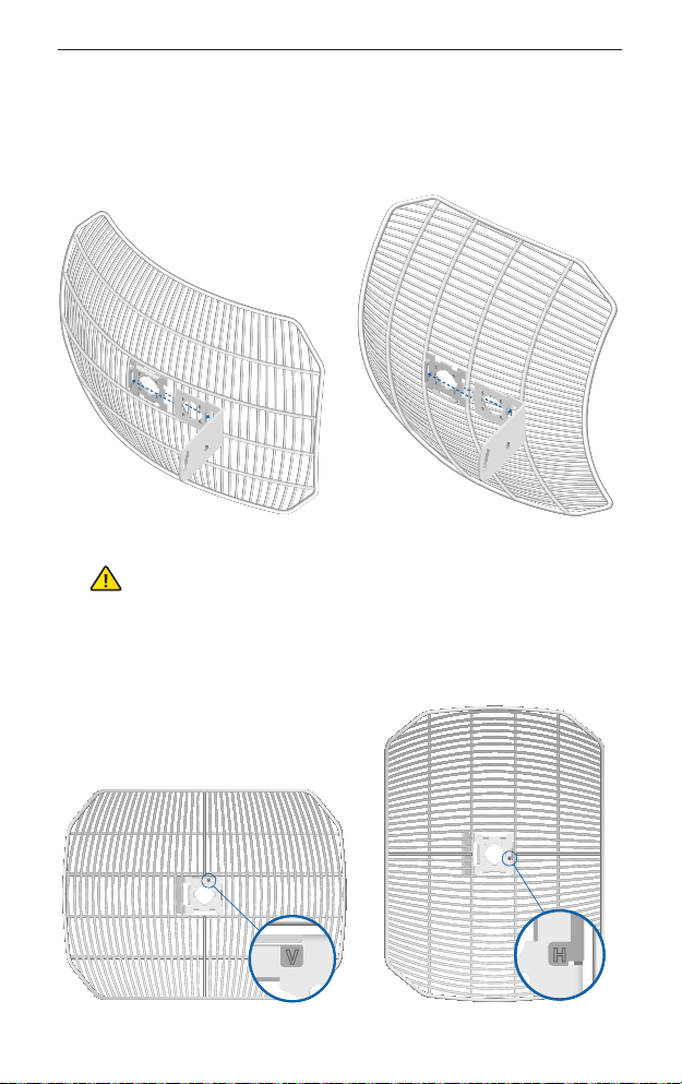
1. Attach the L-Bracket to the Grid Reflector by sliding the tabs
into the slots.
Vertical Polarization Horizontal Polarization
WARNING: The polarization of the airGrid must match
the polarization of its corresponding device (horizontal
to horizontal, vertical to vertical).
2. On the front of the airGrid, ensure the polarization mark, V or H,
properly matches your desired polarization.
Vertical Polarization Horizontal Polarization
4
Hardware Installation
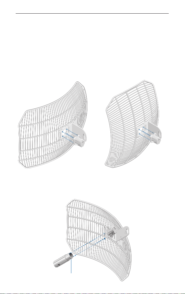
3. Attach the Rear Housing:
a. Ensure the four alignment holes on the Grid Reflector and
L-Bracket are lined up.
b. Orient the Rear Housing with the locking tab of the cable
feed door facing up.
c. Insert the alignments pins of the Rear Housing into the
alignment holes, and push until the Rear Housing locks into
place with a click.
Vertical Polarization Horizontal Polarization
4. Insert the Feed Extender into the Rear Housing with the Release
Button facing down. Push until it locks into place with a click.
Release Button
5
™
airGrid
AGM5-HP-1724 Quick Start Guide
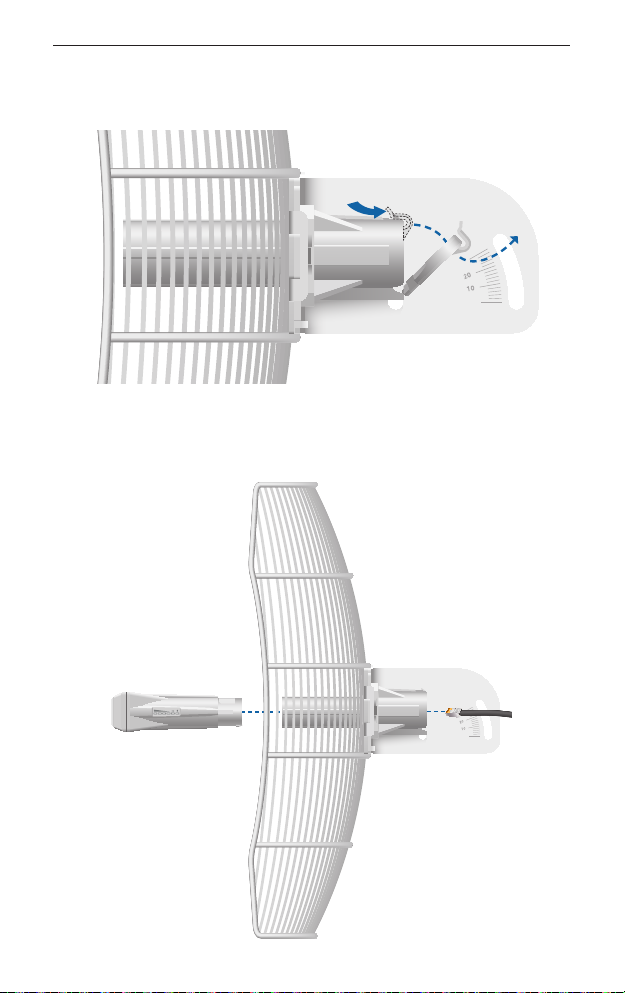
5. Lift the locking tab of the cable feed door and detach the door
from the Rear Housing.
6. Route an Ethernet cable through the Rear Housing and Feed
Extender. Connect the cable to the Ethernet port on the back of
the Antenna Feed.
6
Hardware Installation
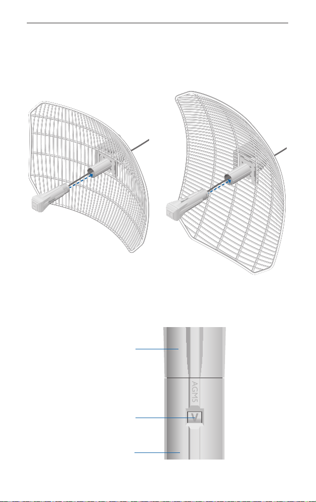
7. Attach the Antenna Feed:
a. Rotate the Antenna Feed to match the signal polarization.
b. Insert the Antenna Feed into the Feed Extender, and push
until it locks into place with a click.
Vertical Polarization Horizontal Polarization
8. Lightly pull the Antenna Feed to ensure that the Release Button
is fully engaged and locked into place.
Antenna Feed
Release Button
Feed Extender
Bottom View
7
 Loading...