

Page 1
24 GHz Point-to-Point Radio
Models: AF-24, AF-24HD
Page 2

Page 3

Table of Contents airFiber AF-24/AF-24HD User Guide
Table of Contents
Chapter 1: Overview ................................................1
Introduction. . . . . . . . . . . . . . . . . . . . . . . . . . . . . . . . . . . . . . . . . . . . . . . . . . . . . . . . . . . . . . . . . . . . . . 1
Package Contents ................................................................1
airFiber Configuration Interface SystemRequirements ............................1
Hardware Overview ..............................................................2
Chapter 2: Installation ..............................................5
Link Planning .....................................................................5
Installation Requirements ........................................................6
Installation Overview .............................................................6
Connecting Power over Ethernet ..................................................6
airFiber Configuration ............................................................7
Hardware Installation .............................................................9
Connecting the GPS Antenna ....................................................11
Connecting Ethernet ............................................................12
Alignment. . . . . . . . . . . . . . . . . . . . . . . . . . . . . . . . . . . . . . . . . . . . . . . . . . . . . . . . . . . . . . . . . . . . . . .13
Chapter 3: Navigation .............................................21
Accessing the airFiber Configuration Interface ...................................21
Navigating the Interface .........................................................22
Notifications ....................................................................23
Product Verification .............................................................23
Chapter 4: Dashboard .............................................25
Link Status ......................................................................25
Statistics ........................................................................26
Device Status ....................................................................27
Ethernet Connection Status ......................................................27
Chapter 5: Wireless Tab ............................................29
Basic Wireless Settings ...........................................................29
Wireless Security ................................................................31
Advanced Wireless Settings ......................................................31
Chapter 6: Network Tab ...........................................33
Management Network Settings ..................................................33
Data Port Ethernet Settings ......................................................34
Ethernet Carrier Drop Settings ...................................................34
i
Ubiquiti Networks, Inc.
Page 4

Table of Contents airFiber AF-24/AF-24HD User Guide
Chapter 7: Services Tab ...........................................37
Ping Watchdog ..................................................................37
SNMP Agent. . . . . . . . . . . . . . . . . . . . . . . . . . . . . . . . . . . . . . . . . . . . . . . . . . . . . . . . . . . . . . . . . . . . .37
Telnet Server ....................................................................38
NTP Client .......................................................................38
Dynamic DNS ...................................................................39
System Log ......................................................................39
Device Discovery ................................................................39
Chapter 8: System Tab ............................................41
Firmware Update ................................................................41
Device ..........................................................................42
Date Settings ....................................................................42
System Accounts ................................................................42
Location ........................................................................43
Device Maintenance .............................................................43
Chapter 9: Tools ...................................................45
Align Antenna ...................................................................45
Discovery .......................................................................46
Ping .............................................................................46
Traceroute ......................................................................46
airView ..........................................................................47
Log .............................................................................49
Appendix A: Specifications ........................................51
Appendix B: Safety Notices ........................................55
Electrical Safety Information .....................................................55
Appendix C: Warranty .............................................57
Limited Warranty ................................................................57
Appendix D: Compliance Information .............................59
Installer Compliance Responsibility ..............................................59
FCC .............................................................................59
ISED Canada. . . . . . . . . . . . . . . . . . . . . . . . . . . . . . . . . . . . . . . . . . . . . . . . . . . . . . . . . . . . . . . . . . . . .59
RF Exposure Warning ............................................................59
CE Marking ......................................................................59
RoHS/WEEE Compliance Statement ..............................................60
Appendix E: Declaration of Conformity ............................61
Appendix F: Contact Information ..................................63
Ubiquiti Networks Support ......................................................63
ii
Ubiquiti Networks, Inc.
Page 5
Chapter 1: OverviewairFiber AF-24/AF-24HD User Guide
Chapter 1: Overview
Introduction
Thank you for purchasing the Ubiquiti Networks®
airFiber® 24 GHz Point-to-Point Radio. This User Guide is
for use with the following models.
Model Description Operating Frequency*
AF-24 24 GHz Point-to-Point 1.4+ Gbps
Radio
AF-24HD 24 GHz Full Duplex Point-to-Point
2 Gbps Radio
* Depends on Regulatory Region. Refer to “Specifications” on page
41 for more information.
The same instructions apply to both models. This User
Guide will refer to both models as the airFiber AF-24 or
AF-24. This User Guide provides installation instructions,
explains how to set up an airFiber link, and shows how to
access and use the airFiber Configuration Interface.
24.05 - 24.24 GHz
24.05 - 24.24 GHz
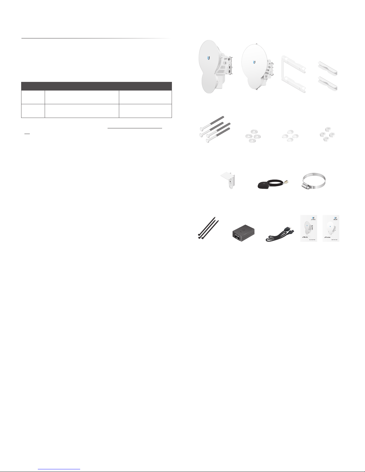
Package Contents
airFiber AF-24 or airFiber AF-24HD Pole Mount
Carriage Bolts
(Qty. 4)
GPS Antenna Mount
(AF-24HD only)
Flat Washers
(Qty. 4)
External GPS Antenna
(AF-24HD only)
Bracket
Split Lock Washers
(Qty. 4)
Pole Clamps
(Qty. 2)
Hex Nuts
(Qty. 4)
Metal Strap
(AF-24HD only)
24 GHz Point to Point
1.4+ Gbps Radio
Model: AF-24
Cable Ties
(Qty. 3)
TERMS OF USE: Ubiquiti radio devices must be professionally installed. Shielded Ethernet cable and
earth grounding must be used as conditions of product warranty. TOUGHCable™ is designed for
outdoor installations. It is the professional installer’s responsibility to follow local country regulations,
including operation within legal frequency channels, output power, and Dynamic Frequency
Selection (DFS) requirements.
Gigabit PoE Adapter
(50V, 1.2A)
Power Cord AF-24 or AF-24HD
Quick Start Guide
24 GHz Full Duplex
Point-to-Point 2 Gbps Radio
Model: AF-24HD
airFiber Configuration Interface
SystemRequirements
• Microsoft Windows 7, Windows 8; Linux; or Mac OS X
• Java Runtime Environment 1.6 (or above)
• Web Browser: Mozilla Firefox, Apple Safari,
GoogleChrome, Microsoft Edge, or Microsoft Internet
Explorer11
Ubiquiti Networks, Inc.
1
Page 6
Chapter 1: Overview airFiber AF-24/AF-24HD User Guide
24 GHz
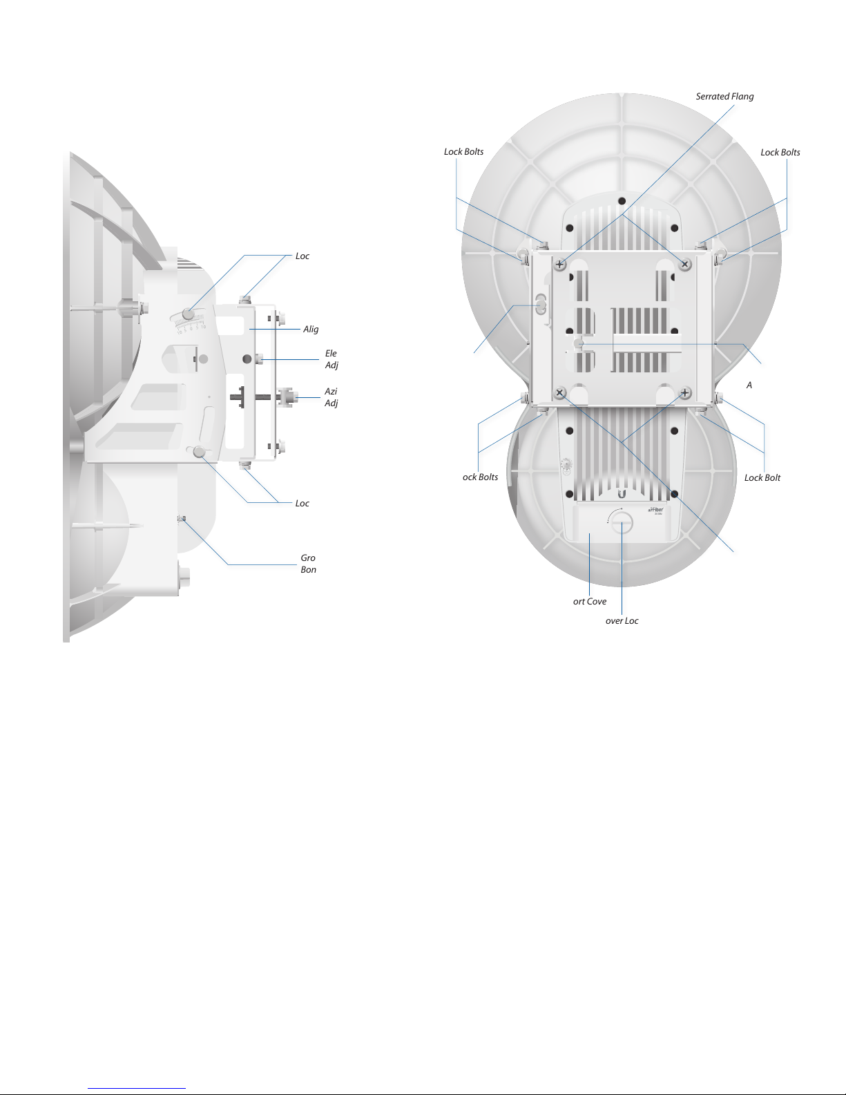
Hardware Overview
AF‑24
Side
Lock Bolts
Alignment Bracket
Elevation
Adjustment
Azimuth
Adjustment
Back
Lock Bolts
Elevation
Adjustment
Serrated Flange Nuts
Lock Bolts
Azimuth
Adjustment
Lock Bolts
Ground
Bonding Point
Lock Bolts
Lock Bolts
24 GHz
Serrated
Flange Nuts
Port Cover
Cover Lock
2
Ubiquiti Networks, Inc.
Page 7
Chapter 1: OverviewairFiber AF-24/AF-24HD User Guide
0
5
10
5
10
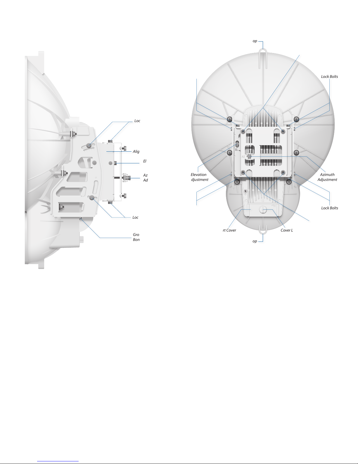
AF‑24HD
Side
Lock Bolts
Alignment Bracket
Elevation
Adjustment
Azimuth
Adjustment
Back
Lock Bolts
Elevation
Adjustment
Lanyard Loop
Serrated
Flange Nuts
Lock Bolts
Azimuth
Adjustment
Lock Bolts
Lock Bolts
Ground
Bonding Point
Lanyard Loop
Cover LockPort Cover
Lock Bolts
Serrated
Flange Nuts
Ubiquiti Networks, Inc.
3
Page 8
Chapter 1: Overview airFiber AF-24/AF-24HD User Guide
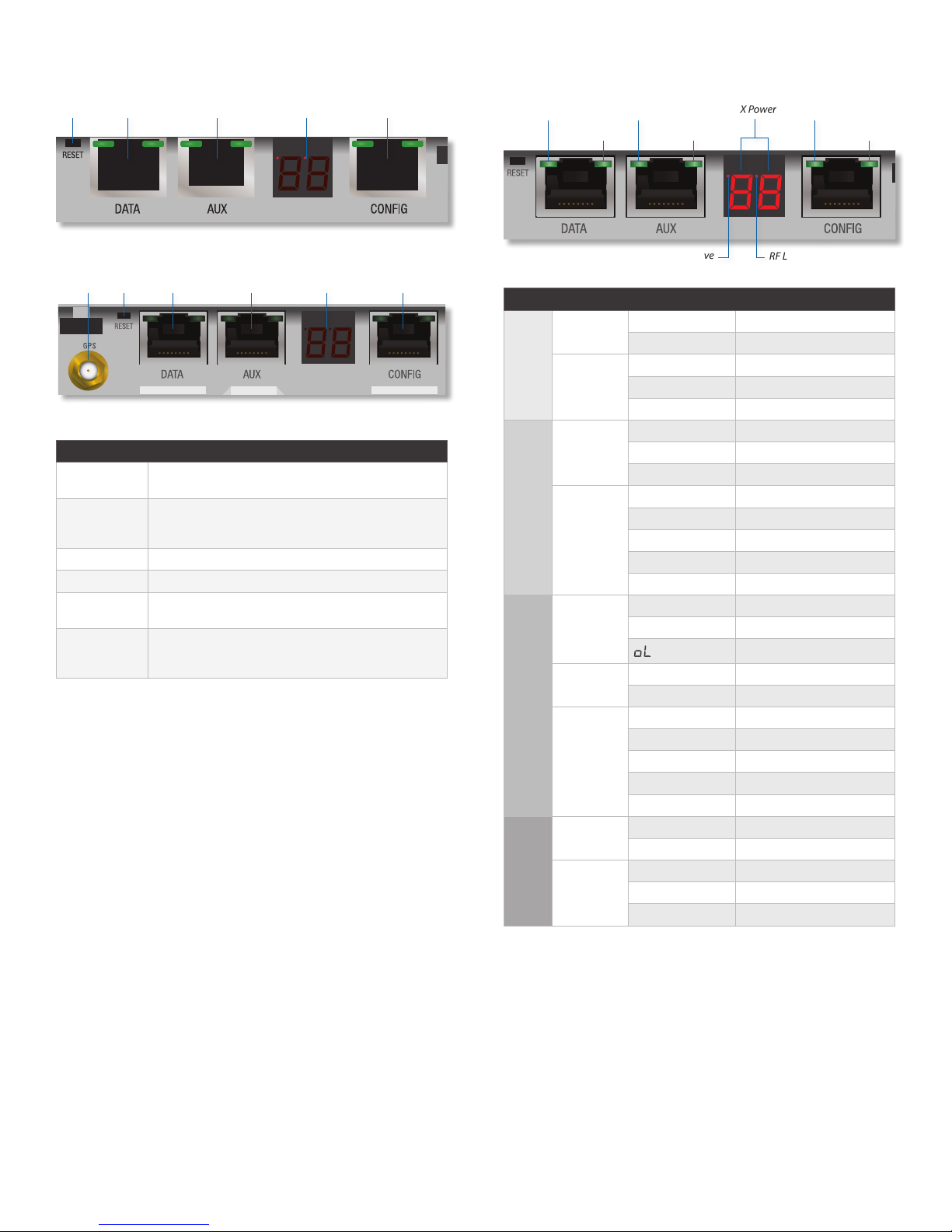
Interfaces
Reset Data AUX ConfigLED Display
AF-24
ResetGPS Data AUX ConfigLED Display
AF-24HD
Interface Description
GPS
Reset
Data 10/100/1000 Mbps port handles all user traffic.
AUX Port for audio tone aiming.
LED Display
Config
(Available only on AF-24HD.) Connect the External
GPS Antenna to this SMA connector.
To reset to factory defaults, press and hold the Reset
button for more than five seconds while the unit is
powered on.
Digital display used for power, status, and mode
information.
10/100 Mbps, secured port for configuration. By
default, this is the only port that can monitor,
configure, and/or update firmware.
LEDs
Speed GPS
LED State Status
Data
AUX
Modulation
RX Power
LED Display
Config
Link/Act
Speed
Link/Act
GPS
(-dBm)
Master/
Slave
RF Link
Status
Speed
Link/Act
SpeedRX Power
Modulation
Master/Slave
Off 10/100 Mbps
On 1000 Mbps
Off No Ethernet Link
On Ethernet Link Established
Random Flashing Ethernet Activity
Off No GPS Synchronization
On Operational (Strong Signal)
Normal Flash* Operational (Weak Signal)
Off ¼x or 1x (QPSK SISO)
Short Flash* 2x (QPSK MIMO)
Normal Flash* 4x (16QAM MIMO)
Long Flash* 6x (64QAM MIMO)
On 8x (256QAM MIMO)
Number Decodable RX Signal
Flashing Number Undecodable RX Signal
Off Slave Mode
On Master Mode
Off RF Off
Short Flash* Syncing
Normal Flash* Beaconing
Long Flash* Registering
On Operational
Off 10 Mbps
On 100 Mbps
Off No Ethernet Link
On Ethernet Link Established
Random Flashing Ethernet Activity
RF Link Status
Overload Condition
Link/Act
4
* Short Flash (1:3 on/off cycle)
Normal Flash (1:1 on/off cycle)
Long Flash (3:1 on/off cycle)
Ubiquiti Networks, Inc.
Page 9
Chapter 2: InstallationairFiber AF-24/AF-24HD User Guide
Master Slave
Chapter 2: Installation
Link Planning
Before you install the airFiber AF-24, there are a few items
to consider:
• Humidity and rain
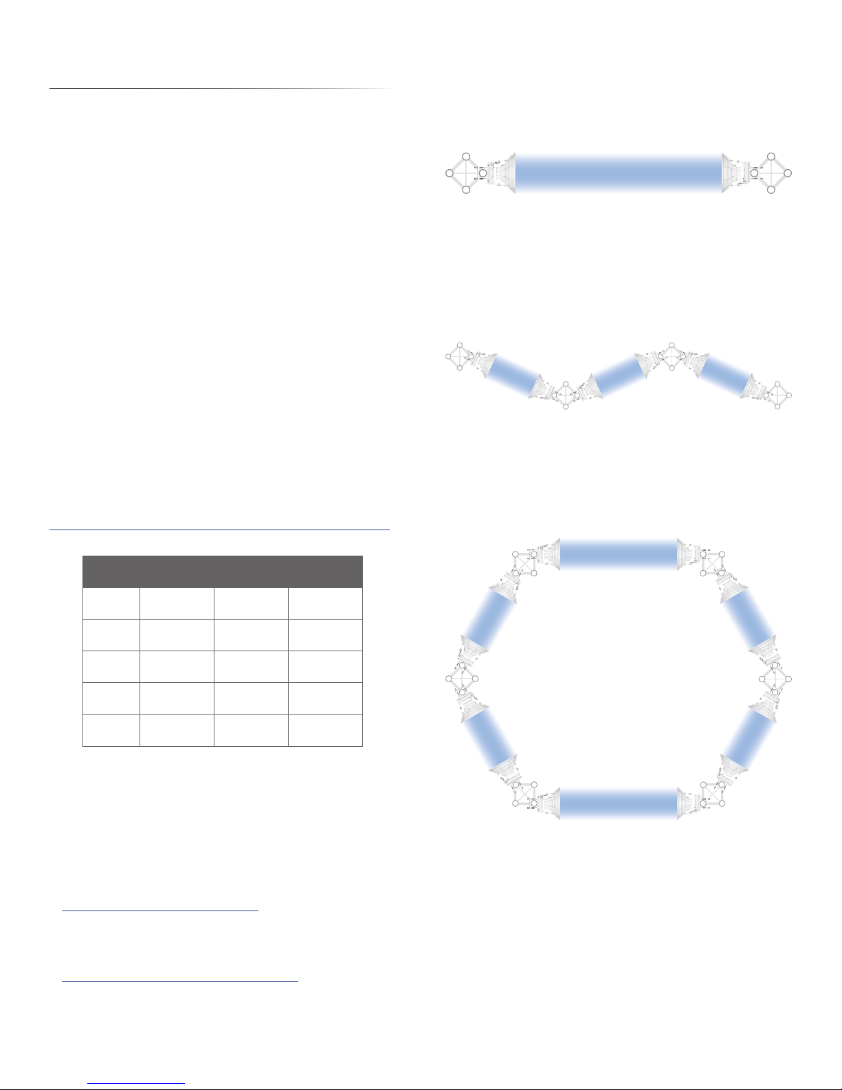
• Point-to-Point (PtP), daisy chain, or ring configuration
• Co-Location
Humidity and Rain
Consider the impact of humidity and rain on your link.
Radio waves in the 24 GHz band encounter additional
atmospheric attenuation beyond that which is expected
in free space due to water absorption, including rain
fade. A general guideline is an additional loss of 1 to 3dB
per kilometer. The amount of additional atmospheric
attenuation will vary, depending on your specific
installation environment (the world has a variety of
rainfallzones).
Here is a hypothetical example: if your link is exposed
to a 25 mm/hr (0.98 in/hr) rate of rainfall, it may have an
additional loss of up to 4 dB/km (6.45 dB/mi).
The table below illustrates the estimated
additional attenuation at various rainfall rates
and distances. This information was derived from
FCC Office of Engineering and Technology Bulletin #70.
Estimated Additional Attenuation at Various Rain Rates andDistances
Distance 1.25 mm/hr
1 km
(0.62 mi)
2 km
(1.2 mi)
3 km
(1.9 mi)
4 km
(2.5 mi)
5 km
(3.1 mi)
(0.05 in/hr)
0.2 dB 0.7 dB 4 dB
0.4 dB 1.4 dB 8 dB
0.6 dB 2.1 dB 12 dB
0.8 dB 2.8 dB 16 dB
1 dB 3.5 dB 20 dB
5 mm/hr
(0.20 in/hr)
25 mm/hr
(0.98 in/hr)
Configuration
There are three typical configurations:
• PtP backhaul Uses two airFiber radios, one configured
as Master and the other configured as Slave.
Point-to-Point Backhaul
• Daisy chain Uses multiple airFiber radios to extend
the distance of a link, like a relay from point to point to
point. The airFiber radios in the same node must use the
same Wireless Mode (Master or Slave).
Master
Slave Slave
Daisy Chain Configuration
• Ring Uses multiple airFiber radios to form redundant
paths. If one link goes down, the other links have an
alternate route available. For each link, configure one
airFiber radio as Master, and configure the other as Slave.
Masters
Slaves
Master Master
Slave
Slaves
Masters
There are a variety of software programs available to help
calculate rain attenuation. For more information about
rain attenuation and rainfall zones, here are a couple of
resources:
• The rain attenuation model described in ITU-R
Recommendation P.530, Propagation data and
prediction methods required for the design of
terrestrial line-of-sight systems, which is available at:
www.itu.int/rec/R-REC-P.530/en
• The rainfall zones described in ITU-R Recommendation
P.837, Characteristics of precipitation for propagation
modelling, which is available at:
http://www.itu.int/rec/R-REC-P.837/en
Ubiquiti Networks, Inc.
Masters Slaves
Ring Configuration
Co-Location
In most cases, co-location interference is not a concern
because the beamwidth is narrow. You can co-locate
multiple airFiber radios if they are pointed in different
directions. Co-located airFiber radios must use the same
Wireless Mode (Master or Slave). Back-to-back airFiber
radios can use the same frequency. We recommend that
you use different frequencies for adjacent airFiber radios;
however, this is not a strict requirement.
5
Page 10
Chapter 2: Installation airFiber AF-24/AF-24HD User Guide
Installation Requirements
• 17 mm (⁄") wrench
• 13 mm (½") socket wrench or driver
• Clear line of sight between airFiber radios
• Clear view of the sky for proper GPS operation
• Mounting location with < 0.5° displacement due to twist
and sway under wind loading
• Mounting point:
• At least 1 m (3.28 ft) below the highest point on the
structure
• For tower installations, at least 3 m (9.84 ft) below the
top of thetower
• Ground wires – min. 8 AWG (10 mm2) and max. length:
1m(3.28ft). As a safety precaution, ground the
airFiber radios to grounded masts, poles, towers, or
groundingbars.
WARNING: Failure to properly ground your
airFiber units will void your warranty.
• (Recommended) 2 Outdoor GigE PoE surge protectors
Note: For guidelines about grounding and
lightning protection, follow your local electrical
regulatory codes.
• Outdoor, shielded Category 5e (or above) cabling
and shielded RJ-45 connectors should be used for all
wired Ethernet connections. Category 6 is required for
installations with long cable runs (up to 100 m).
We recommend that you protect your networks
from harmful outdoor environments and destructive
ESD events with industrial-grade shielded Ethernet
cable from Ubiquiti Networks. For more details, visit
www.ubnt.com/toughcable
Connecting Power over Ethernet
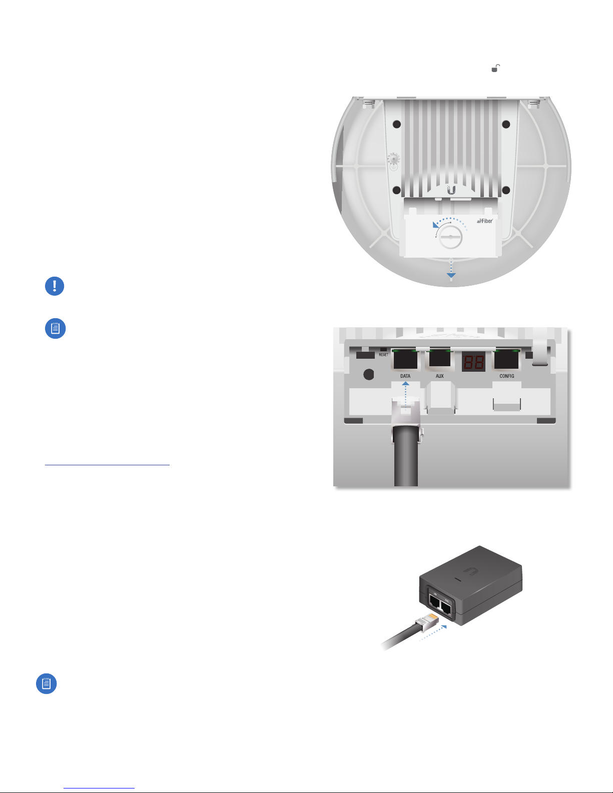
1. Turn the Cover Lock to the Unlocked icon. Slide the
Port Cover down to remove it.
24 GHz
2. Connect an Ethernet cable to the Data port.
Installation Overview
We recommend that you configure your paired airFiber
radios before mounting. Below is an overview of the
installation with specific details on the following pages:
• Connect Power over Ethernet to the Data port, and
connect an Ethernet cable between your computer and
the Config port.
• Configure the device settings in the airFiber
Configuration Interface.
• Once configuration is complete, disconnect the cables
to move the airFiber radios.
• Reconnect at the site.
• After you have mounted the airFiber radios, establish
and optimize the RF link.
Note: Throughout the rest of this chapter, only
the AF-24 is shown in illustrations (the AF-24HD is
similar), unless necessary to avoid confusion.
6
3. Connect the other end of the Ethernet cable from the
Data port to the Ethernet port labeled POE on the PoE
Adapter.
Ubiquiti Networks, Inc.
Page 11
Chapter 2: InstallationairFiber AF-24/AF-24HD User Guide
SlaveMaster
SlaveMaster
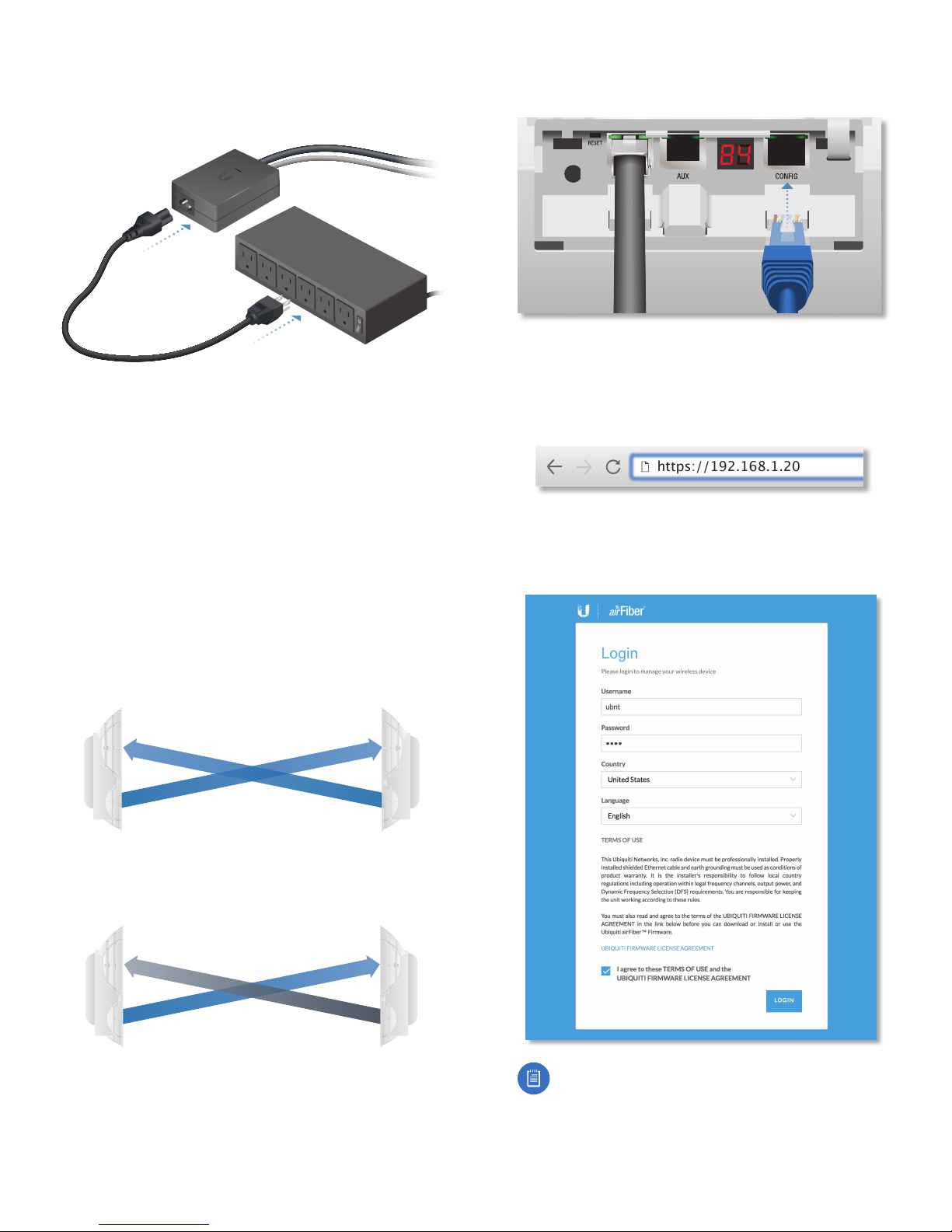
4. Connect the Power Cord to the power port on the PoE
Adapter. Connect the other end of the Power Cord to a
power source.
airFiber Configuration
The instructions in this section explain how to access
the airFiber Configuration Interface and configure the
following settings:
• Wireless Mode Configure one airFiber AF-24 as the
Master and the other as the Slave.
• Duplex The airFiber AF-24 supports both half-duplex
and full-duplex operation. Half-duplex operation
provides more frequency planning options at the
cost of higher latency and throughput. Full-duplex
operation provides the highest throughput and
lowest latency; however, you have fewer frequency
managementoptions.
- Half Duplex (default) The TX and RX Frequencies can
be the same or different to suit local interference.
1. Connect an Ethernet cable from your computer to the
Config port on the airFiber AF-24.
2. Configure the Ethernet adapter on your computer
with a static IP address on the 192.168.1.x subnet (for
example, 192.168.1.100).
3. Launch your web browser. Type http://192.168.1.20 in
the address field and press enter (PC) or return (Mac).
https://192.168.1.20
4. The login screen will appear. Enter ubnt in the
Username and Password fields. Select your Country and
Language. You must agree to the Terms of Use to use
the product. Click Login.
RX
Frequency A
TX
Half-Duplex Diagram
RX
Frequency A
TX
- Full Duplex The TX and RX Frequencies should be
different.
RX
Frequency A
TX
Full-Duplex Diagram
RX
Frequency B
TX
• TX and RX Frequencies The TX Frequency on the
Master must match the RX Frequency on the Slave, and
vice versa.
Note: U.S. product versions are locked to the U.S.
Country Code to ensure compliance with FCC
regulations.
Ubiquiti Networks, Inc.
7
Page 12
Chapter 2: Installation airFiber AF-24/AF-24HD User Guide
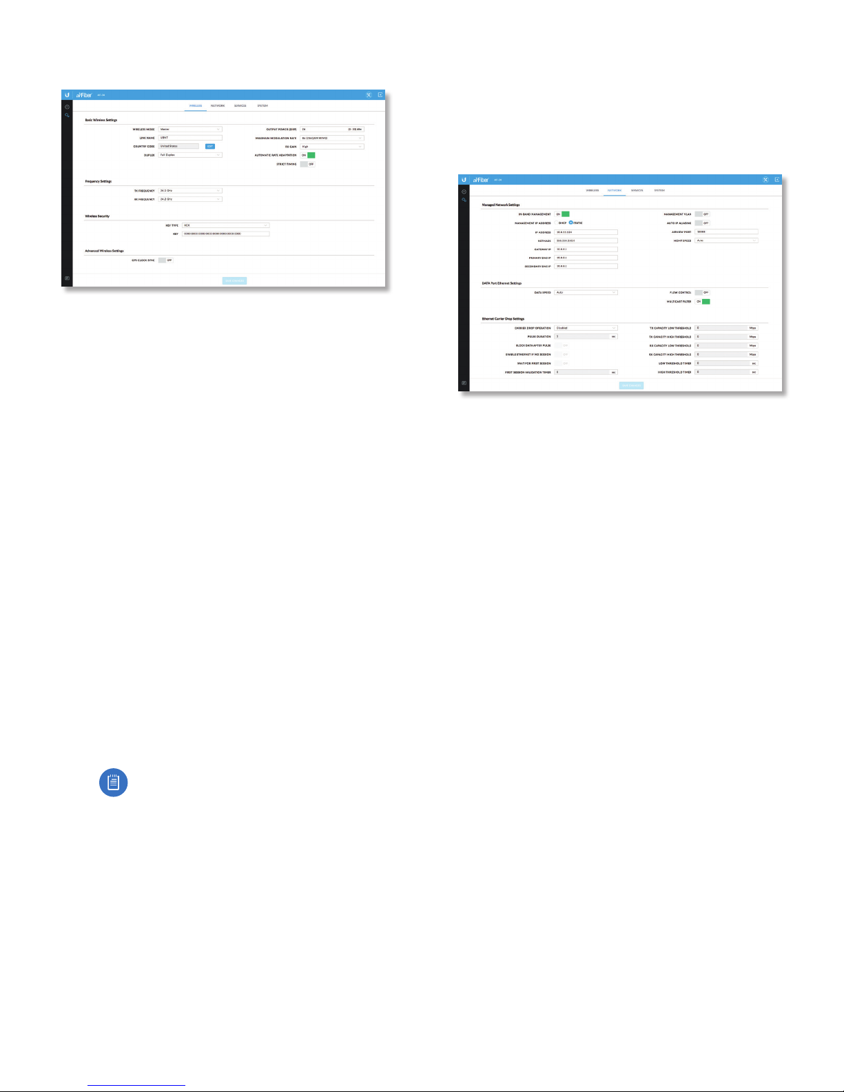
5. Click the Wireless tab.
6. Enter the Basic Wireless Settings:
a. For one airFiber AF-24, select Master from the
Wireless Mode drop-down. For the other airFiber
AF-24, keep the default, Slave.
b. Enter a name in the Link Name field. This should be
the same on both the Master and the Slave.
c. For the Duplex drop-down:
- Half Duplex The default mode. The TX and RX
Frequencies can be the same or different to suit
local interference.
- Full Duplex The TX and RX Frequencies should be
different.
d. Select a TX Frequency. This must match the RX
Frequency on your other airFiber AF-24.
e. Select a RX Frequency. This must match the TX
Frequency of your other airFiber AF-24.
f. If needed, change the Output Power, Maximum
Modulation Rate, and/or RX Gain settings.
7. Configure the Wireless Security:
a. Select the AES Key Type, HEX or ASCII.
b. For the Key field:
- HEX Enter 16 bytes (eight, 16-bit HEX values: 0-9,
A-F, or a-f ). You can omit zeroes and use colons,
similar to the IPv6 format.
Note: The airFiber Configuration Interface
supports IPv6 formats excluding dotted
quad and “::” (double-colon) notation.
- ASCII Enter a combination of alphanumeric
characters (0-9, A-Z, or a-z).
8. Click Change and then click Apply.
9. In-Band Management is enabled by default, so each
airFiber radio must have a unique IP Address. (If the
airFiber radios use the same IP Address, then you may
lose access to the airFiber radios via the Data ports.) To
change the network settings:
a. Click the Network tab.
b. Change the IP Address, Netmask, and other settings
to make them compatible with your network.
c. Click Change and then click Apply.
Repeat the instructions in the airFiber Configuration
section on your other airFiber radio. After you have
configured the airFiber radios, disconnect them and move
them to your installation site.
8
Ubiquiti Networks, Inc.
Page 13
Chapter 2: InstallationairFiber AF-24/AF-24HD User Guide
6 mm
Hardware Installation
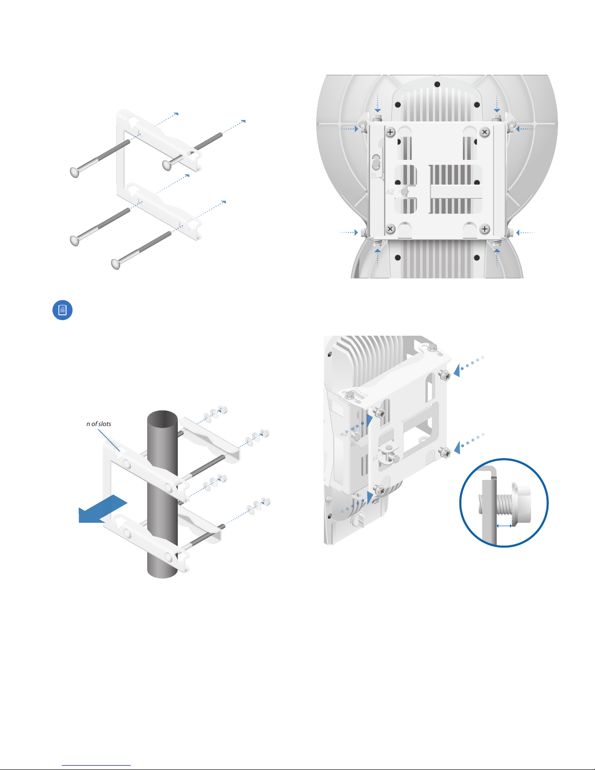
To install the airFiber AF-24:
1. Insert the four Carriage Bolts into the Pole Mount
Bracket.
2. Attach the Pole Mount Bracket to a pole.
Note: The mounting assembly can
accommodate a Ø 51 - 101 mm (2.0" - 4.0") pole.
a. Orient the Pole Mount Bracket around the pole so it
is aimed in the direction of the other airFiber AF-24.
b. Insert the Carriage Bolts into the Pole Clamps.
c. Secure the clamps with the Flat Washers, Split Lock
Washers, and Hex Nuts.
3. Loosen, but do NOT remove the eight Lock Bolts
located on the Alignment Bracket.
4. Ensure that there is a 6 mm (0.24 in) gap between the
head of each Serrated Flange Screw and the Alignment
Bracket.
Note orientation of slots
Aim towards link.
Ubiquiti Networks, Inc.
9
Page 14
Chapter 2: Installation airFiber AF-24/AF-24HD User Guide
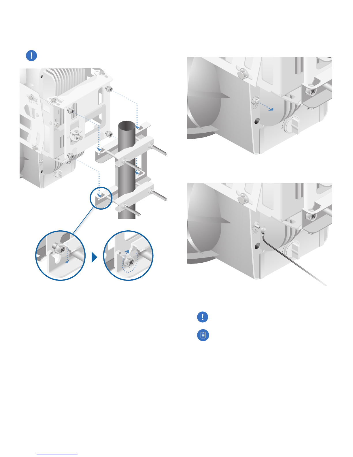
5. Lift the airFiber AF-24 and align the four Serrated Flange
Screws with the slots on the Pole Mount Bracket. Seat
the screws in the slots. Securely tighten the screws.
WARNING: To prevent injury, ensure that all four
screws are seated and fully tightened.
Grounding
To attach a ground wire:
1. Remove the nut from the Ground Bonding Point.
2. Attach a ground wire (min. 8 AWG or 10 mm2) to the
lug and replace the nut to secure the wire.
10
3. Secure the other end of the ground wire to a grounded
mast, pole, tower, or grounding bar.
WARNING: Failure to properly ground your
airFiber units will void your warranty.
Note: The grounding wire should be as short as
possible and no longer than 1 meter (3.28 ft) in
length.
Ubiquiti Networks, Inc.
Page 15
Chapter 2: InstallationairFiber AF-24/AF-24HD User Guide
Connecting the GPS Antenna
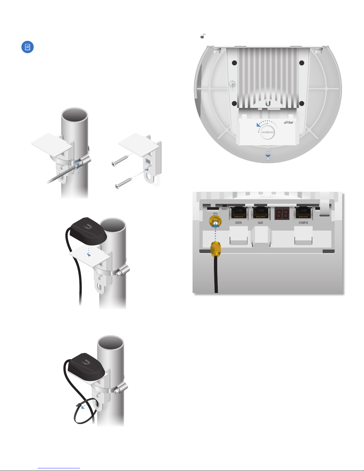
Note: This section applies to the AF-24HD only.
Locate a mounting point for the External GPS Antenna that
has a clear view to the sky, and is above and as far away as
possible from the AF -24HD
1. Attach the GPS Antenna Mount to a pole using the
included Metal Strap, or attach it to a wall using the
appropriate fasteners (not included).
4. Turn the Cover Lock counterclockwise to the Unlocked
icon. Slide the Port Cover down to remove it.
24 GHz
5. Connect the External GPS Antenna to the GPS SMA
connector.
2. Place the magnetic External GPS Antenna on the mount.
3. Secure the cable of the External GPS Antenna to the
mount with a Cable Tie.
Ubiquiti Networks, Inc.
11
Page 16
Chapter 2: Installation airFiber AF-24/AF-24HD User Guide
Connecting Ethernet
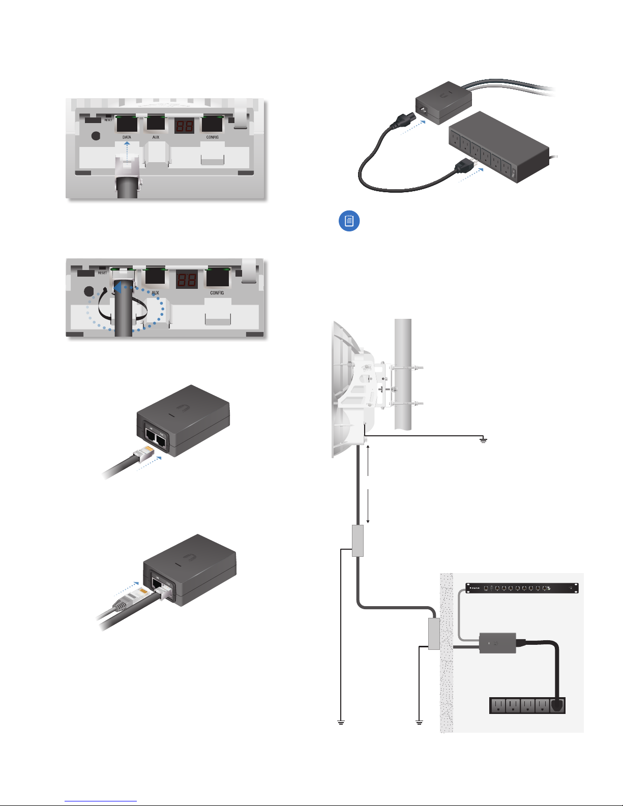
1. Connect a TOUGHCable or other outdoor, shielded
CAT5e/6 cable to the Data port.
2. Create a strain relief for the Ethernet cable by feeding
a cable tie through the tie slot under the cable. Then
wrap the cable tie around the cable and tighten.
5. Connect the Power Cord to the PoE Adapter, and then
plug the Power Cord into a power outlet.
Note: For added protection, we recommend
installing two GigE PoE surge protectors. Install
the first surge protector within one meter of the
airFiber Data port, and install the second surge
protector at the ingress point of the location
housing the wired network equipment.
Below is a diagram of a finished installation with
recommended surge protectors installed.
3. Connect the Ethernet cable from the Data port to the
POE port on the PoE Adapter.
4. Connect an Ethernet cable from your LAN to the LAN
port on the PoE Adapter.
Max. 1 m (3.28 ft)
Outdoor GigE PoE
Surge Protector
Outdoor GigE PoE
Surge Protector
Ground to Pole, Tower, or
Grounding Block:
Max. 1 m (3.28 ft) from
Ground Bonding Point
EdgeRouter
™
12
GigE PoE Adapter
Power Source
Ubiquiti Networks, Inc.
Page 17
Chapter 2: InstallationairFiber AF-24/AF-24HD User Guide
Alignment
Tips
• Fine-tuning is best achieved by a pair of installers with
a dedicated, two-way communication link: one installer
makes adjustments on one airFiber radio while the other
installer reports the received signal level at the other
airFiber radio. Fine-tuning (see “Fine-Tuning the Link”
on page15) is necessary because the main lobe of
the receiver is narrower than that of the transmitter, in
both azimuth and elevation.
• To accurately align the airFiber radios for best
performance, you MUST align only one end of the link at
a time.
• For more convenient alignment, you may consider using
long-range scopes (not included) temporarily attached
to your airFiber radios.
• You may need to use additional hardware to
compensate for issues such as the improper orientation
of a mounting pole or significant elevation differences
between the airFiber radios.
Determining the Received Signal Level
There are three ways to determine the received signal
level:
• LED Display (See the following section, Using the LED
Display.)
• airFiber Configuration Interface (See “Using the
airFiber Configuration Interface” on page15.)
• Audio tone (Optional equipment required. See “Using
the Audio Tone” on page18.)
Using the LED Display
Establishing a Preliminary Link
Adjust the positions of the Master and the Slave to
establish a preliminary link. This requires the Master
and Slave to be within a few degrees of the line of sight
between the airFiber radios.
Note: The Master must be aimed first at the Slave
because the Slave does not transmit any RF signal
until it detects transmissions from the Master.
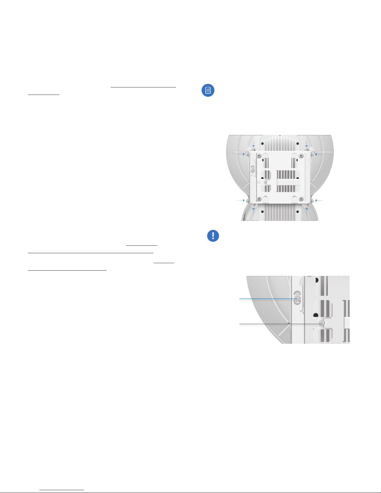
1. For the Master and Slave, ensure the eight Lock Bolts on
the Alignment Bracket are sufficiently loose by spinning
each washer by hand.
WARNING: All Lock Bolts MUST be loose to avoid
damage to the airFiber housing.
2. For the Master and Slave, ensure the Azimuth (AZ) and
Elevation (EL) Adjustment Bolts are in the middle of their
adjustmentranges.
Ubiquiti Networks, Inc.
Elevation (EL)
Adjustment Bolt
Azimuth (AZ)
Adjustment Bolt
13
Page 18
Chapter 2: Installation airFiber AF-24/AF-24HD User Guide
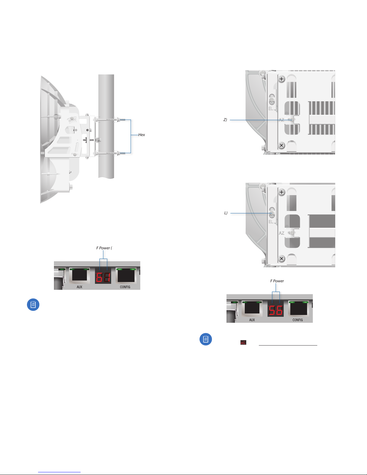
3. Master Aim the Master at the Slave. If necessary, adjust
the Master’s position on the pole:
a. Loosen the Hex Nuts.
b. Adjust the Pole Mount Bracket and Pole Clamps.
c. Tighten the Hex Nuts.
Hex Nuts
5. Master Adjust the azimuth and elevation of the Master
until the strongest received signal level is displayed on
the LED Display of the Master.
a. Sweep the Azimuth (AZ) Adjustment Bolt of the
Master through its adjustment range.
Master
Azimuth (AZ)
Adjustment Bolt
b. Sweep the Elevation (EL) Adjustment Bolt of the
Master through its adjustment range.
4. Slave Aim the Slave at the Master to achieve the
strongest received signal level on the Slave’s numeric
LED Display, which is located next to the Config port. If
necessary, adjust the Slave’s position on the pole.
Slave RF Power (-dBm)
Note: Values on the LED Display are displayed in
negative (-) dBm. For example, 61 represents a
received signal level of -61 dBm, which is stronger
than -72 dBm.
Master
Elevation (EL)
Adjustment Bolt
Master RF Power (-dBm)
Note: If the LED Display indicates an overload
condition , see “RX Gain” on page30
for more details about RX Gain and overload
condition.
14
Ubiquiti Networks, Inc.
Page 19
Chapter 2: InstallationairFiber AF-24/AF-24HD User Guide
Fine-Tuning the Link
The Azimuth (AZ) and Elevation (EL) Adjustment Bolts of
the Alignment Bracket adjust the azimuth and elevation
within a range of ±10°. For accurate alignment, make
adjustments on one end of the link while the other
installer reports the received signal level at the other end
of the link. Do NOT make simultaneous adjustments on
the Master and Slave.
1. Slave Adjust the azimuth and elevation of the Slave
until the other installer sees the strongest received
signal level displayed on the LED Display of the Master.
2. Master Adjust the azimuth and elevation of the Master
until the other installer sees the strongest received
signal level displayed on the LED Display of the Slave.
3. Repeat steps 1 and 2 until you achieve a symmetric
link, with the received signal levels within 1 dB of each
other. This ensures the best possible data rate between
the airFiber radios.
4. Lock the alignment on both airFiber radios by
tightening all eight Lock Bolts on the Alignment Bracket.
5. Observe the LED Display on each airFiber AF-24
to ensure that the value remains constant while
tightening the Lock Bolts. If the LED value changes
during the locking process, loosen the Lock Bolts,
finalize the alignment of each airFiber AF-24 again, and
retighten the Lock Bolts.
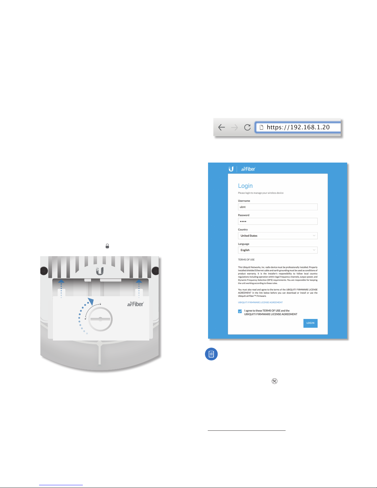
6. For each airFiber AF-24, attach the Port Cover and turn
the Cover Lock to the Locked icon.
Using the airFiber Configuration Interface
Before You Begin
Access the airFiber Configuration Interface:
1. Make sure that your computer that is connected to the
Config port on the airFiber AF-24.
2. Configure the Ethernet adapter on your computer
with a static IP address on the 192.168.1.x subnet (for
example, 192.168.1.100).
3. Launch your web browser. Type http://192.168.1.20 in
the address field and press enter (PC) or return (Mac).
https://192.168.1.20
4. The login screen will appear. Enter ubnt in the
Username and Password fields, and click Login.
Ubiquiti Networks, Inc.
24 GHz
Note: U.S. product versions are locked to the U.S.
Country Code to ensure compliance with FCC
regulations.
5. The Dashboard of the airFiber Configuration Interface
appears. Click the Tools drop-down list at the top
right corner of the page.
6. Click Alignment. You will use the Align Antenna tool
to point and optimize the antenna in the direction of
maximum link signal. (The Antenna Alignment window
is designed to refresh every 250 milliseconds. See
“Align Antenna” on page45 for more details.)
15
Page 20
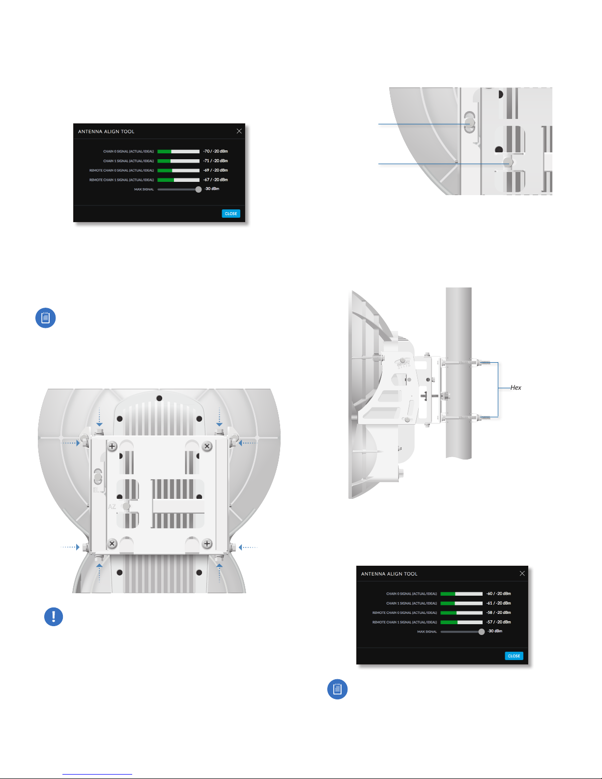
Chapter 2: Installation airFiber AF-24/AF-24HD User Guide
7. The Antenna Alignment window appears, displaying
the Signal Strengths for both airFiber radios. The Chain
Signal Strength bar graphs display the Signal Strengths
for the airFiber AF-24 you have accessed, while the
Remote Signal Strength bar graphs display the Signal
Strengths for the other airFiber AF-24.
Establishing a Preliminary Link
Adjust the positions of the Master and the Slave to
establish a preliminary link. This requires the Master
and Slave to be within a few degrees of the line of sight
between the airFiber radios.
Note: The Master must be aimed first at the Slave
because the Slave does not transmit any RF signal
until it detects transmissions from the Master.
1. For the Master and Slave, ensure the eight Lock Bolts on
the Alignment Bracket are sufficiently loose by spinning
each washer by hand.
2. For the Master and Slave, ensure the Azimuth (AZ) and
Elevation (EL) Adjustment Bolts are in the middle of their
adjustmentranges.
Elevation (EL)
Adjustment Bolt
Azimuth (AZ)
Adjustment Bolt
3. Master Aim the Master at the Slave. If necessary, adjust
the Master’s position on the pole:
a. Loosen the Hex Nuts.
b. Adjust the Pole Mount Bracket and Pole Clamps.
c. Tighten the Hex Nuts.
Hex Nuts
WARNING: All Lock Bolts MUST be loose to avoid
damage to the airFiber housing.
16
Master
4. Slave Aim the Slave at the Master to achieve the
strongest Signal Strengths for the Slave. If necessary,
adjust the Slave’s position on the pole.
Note: The Signal Strength bar graphs display the
absolute power level (in dBm) of the received
signal for each chain. Lower values indicate
stronger received signal levels.
Ubiquiti Networks, Inc.
Page 21
Chapter 2: InstallationairFiber AF-24/AF-24HD User Guide
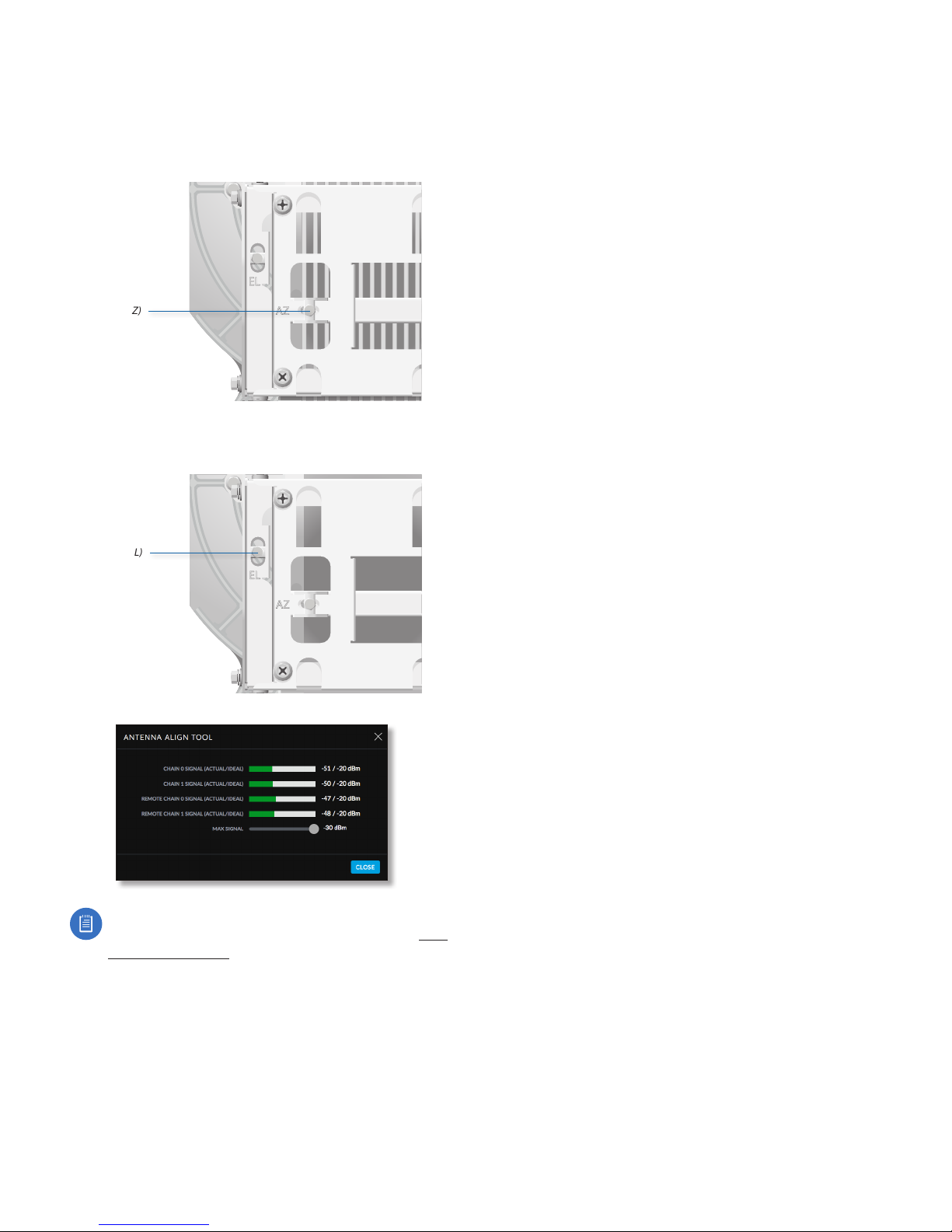
5. Master Adjust the azimuth and elevation of the Master
until the strongest Signal Strengths are displayed for
the Master.
a. Sweep the Azimuth (AZ) Adjustment Bolt of the
Master through its adjustment range.
Master
Azimuth (AZ)
Adjustment Bolt
b. Sweep the Elevation (EL) Adjustment Bolt of the
Master through its adjustment range.
Master
Elevation (EL)
Adjustment Bolt
Fine-Tuning the Link
The Azimuth (AZ) and Elevation (EL) Adjustment Bolts of
the Alignment Bracket adjust the azimuth and elevation
within a range of ±10°. For accurate alignment, make
adjustments on one end of the link using the Signal
Strengths for the airFiber radio at the other end of the link.
Do NOT make simultaneous adjustments on the Master
and Slave.
1. Slave Adjust the azimuth and elevation of the Slave
until the other installer sees the strongest Signal
Strengths for the Master.
2. Master Adjust the azimuth and elevation of the Master
until the other installer sees the strongest Signal
Strengths for the Slave.
3. Repeat steps 1 and 2 until you achieve a symmetric
link, with the Signal Strengths within 1 dB of each other.
This ensures the best possible data rate between the
airFiber radios.
4. Lock the alignment on both airFiber radios by
tightening all eight Lock Bolts on the Alignment Bracket.
Observe the Antenna Alignment window to ensure that the
values remain constant while tightening the Lock Bolts. If
the values change during the locking process, loosen the
Lock Bolts, finalize the alignment of each airFiber AF-24
again, and retighten the Lock Bolts.
Note: If the Antenna Alignment window displays
“Overload” to indicate overload condition, see “RX
Gain” on page30 for more details about RX
Gain and overload condition.
Ubiquiti Networks, Inc.
17
Page 22
Chapter 2: Installation airFiber AF-24/AF-24HD User Guide
Using the Audio Tone
Before You Begin
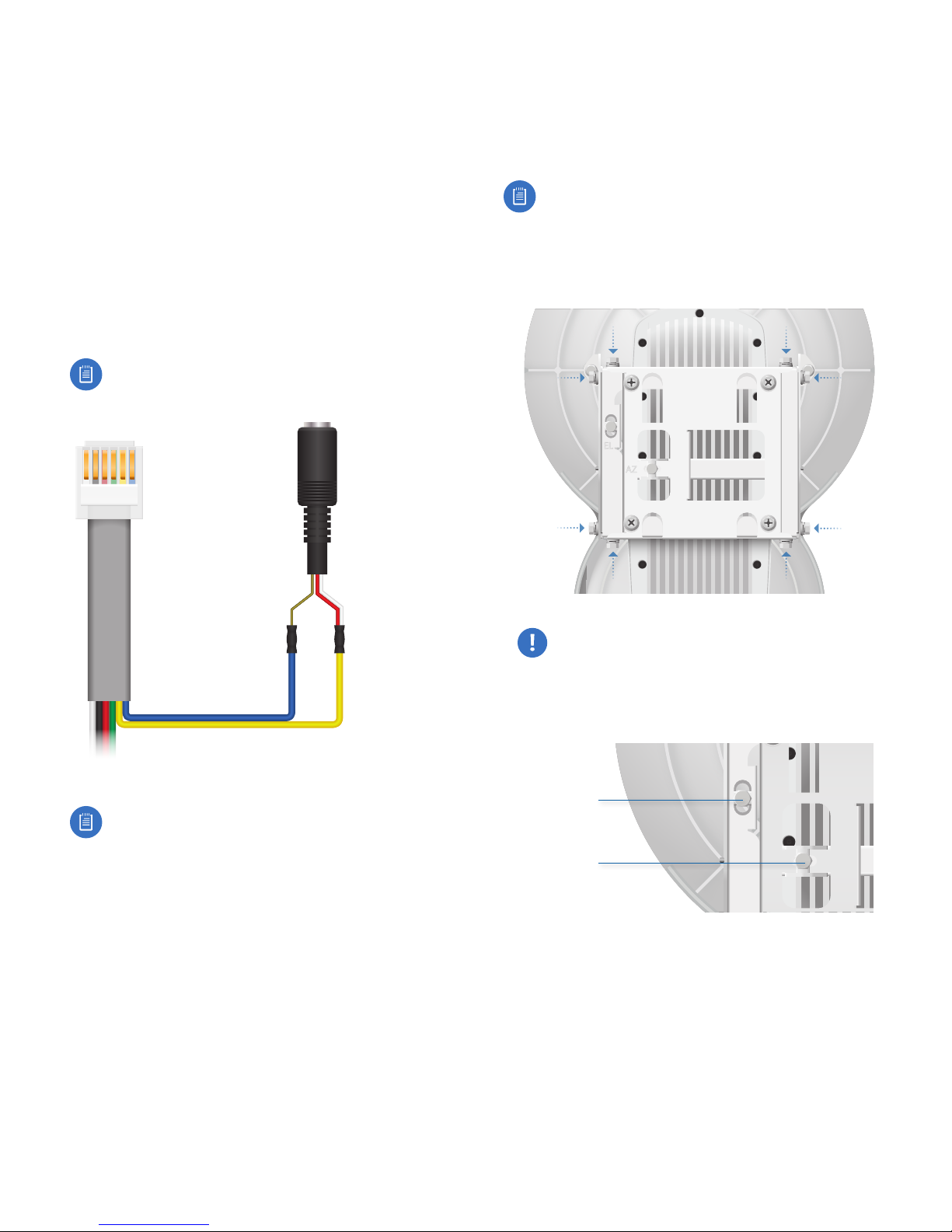
Create your own cable adapter to connect the AUX port
to your headphones or other listening device. The cable
adapter requires two items:
• An RJ-12 cable with an RJ-12 connector
• A cable with a 3.5 mm, female, stereo phono jack (mono
jack is acceptable)
1. Attach the wire from pin 6 of the RJ-12 cable to the
return or shield wire of the 3.5 mm jack.
2. Attach the wire from pin 5 of the RJ-12 cable to both
the left and right channel wires of the 3.5 mm stereo
phono jack.
Note: For a mono jack, connect the wire from pin 5
to the + wire of the mono jack.
Pin
1 2 3 4 5 6
RJ-12 Connector
Audio Jack
Establishing a Preliminary Link
Adjust the positions of the Master and the Slave to
establish a preliminary link. This requires the Master
and Slave to be within a few degrees of the line of sight
between the airFiber radios.
Note: The Master must be aimed first at the Slave
because the Slave does not transmit any RF signal
until it detects transmissions from the Master.
1. For the Master and Slave, ensure the eight Lock Bolts on
the Alignment Bracket are sufficiently loose by spinning
each washer by hand.
Return/Shield Left/Right
Channel
Wire to Pin 6 Wire to Pin 5
Pinouts from RJ-12 to 3.5 mm Stereo Phono Jack
Note: Wire colors may vary on RJ-12 cables.
3. Attach the RJ-12 connector to the AUX port of the
airFiber AF-24.
4. Connect a pair of headphones (or other listening
device) to the female audio jack.
WARNING: All Lock Bolts MUST be loose to avoid
damage to the airFiber housing.
2. For the Master and Slave, ensure the Azimuth (AZ) and
Elevation (EL) Adjustment Bolts are in the middle of their
adjustmentranges.
Elevation (EL)
Adjustment Bolt
Azimuth (AZ)
Adjustment Bolt
18
Ubiquiti Networks, Inc.
Page 23
Chapter 2: InstallationairFiber AF-24/AF-24HD User Guide
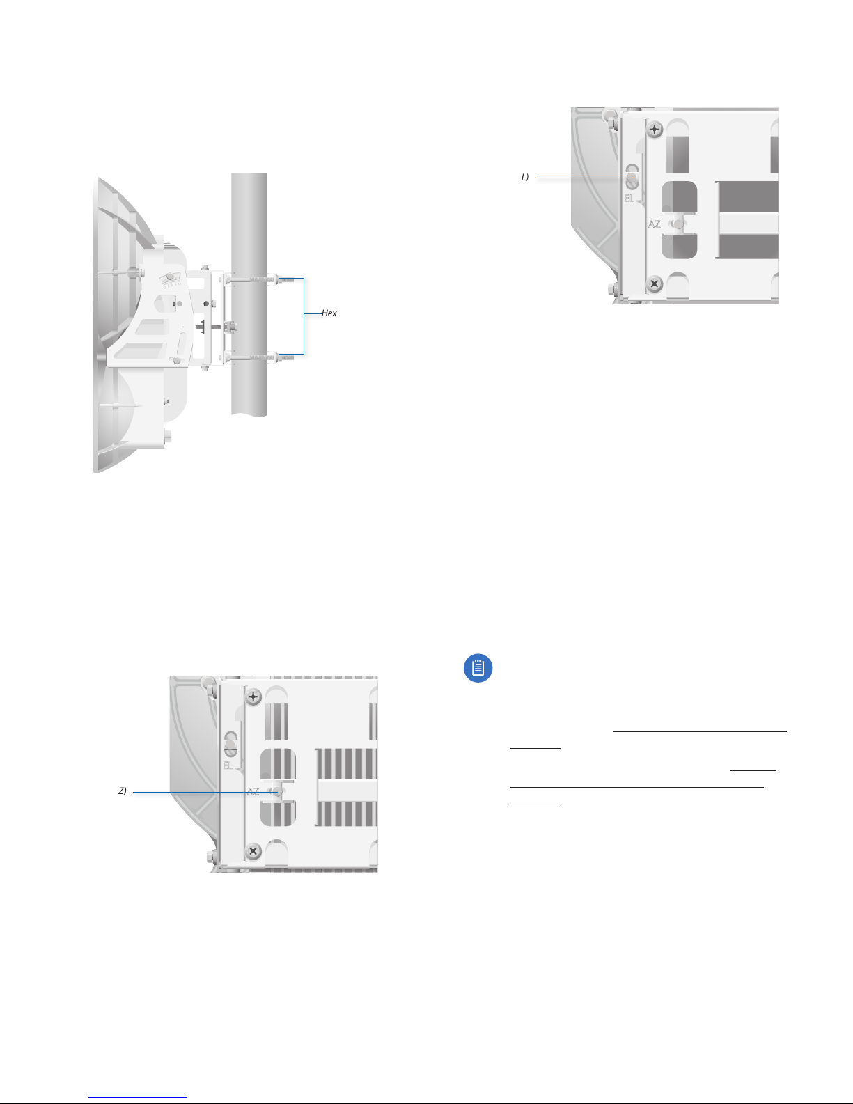
3. Master Aim the Master at the Slave. If necessary, adjust
the Master’s position on the pole:
a. Loosen the Hex Nuts.
b. Adjust the Pole Mount Bracket and Pole Clamps.
c. Tighten the Hex Nuts.
Hex Nuts
Master
4. Slave Listen to the audio tone of the Slave – the higher
the pitch, the stronger the signal strength. Aim the
Slave at the Master to achieve the strongest signal
strength. If necessary, adjust the Slave’s position on
thepole.
5. Master Adjust the azimuth and elevation of the Master
until you hear the highest pitch for the Master.
a. Sweep the Azimuth (AZ) Adjustment Bolt of the
Master through its adjustment range.
Master
Azimuth (AZ)
Adjustment Bolt
b. Sweep the Elevation (EL) Adjustment Bolt of the
Master through its adjustment range.
Master
Elevation (EL)
Adjustment Bolt
Fine-Tuning the Link
The Azimuth (AZ) and Elevation (EL) Adjustment Bolts of
the Alignment Bracket adjust the azimuth and elevation
within a range of ±10°. For accurate alignment, make
adjustments on one end of the link while the other
installer listens to the audio tone at the other end of the
link. Do NOT make simultaneous adjustments on the
Master and Slave.
1. Slave Adjust the azimuth and elevation of the Slave
until the other installer hears the highest pitch for the
Master.
2. Master Adjust the azimuth and elevation of the Master
until the other installer hears the highest pitch for the
Slave.
3. Repeat steps 1 and 2 until you achieve a symmetric
link, with the received signal levels within 1 dB of each
other. This ensures the best possible data rate between
the airFiber radios.
Note: If you have difficulty discerning whether the
link is symmetric, you can use one of the following
methods to determine more precise received
signal level readings.
• LED Display (See “Using the LED Display” on
page13.)
• airFiber Configuration Interface (See “Using
the airFiber Configuration Interface” on
page15.)
4. Lock the alignment on both airFiber radios by
tightening all eight Lock Bolts on the Alignment Bracket.
Listen to the audio tone for each airFiber AF-24 to ensure
that the value remains constant while tightening the
Lock Bolts. If the audio tones change during the locking
process, loosen the Lock Bolts, finalize the alignment of
each airFiber AF-24 again, and retighten the Lock Bolts.
Ubiquiti Networks, Inc.
19
Page 24

Chapter 2: Installation airFiber AF-24/AF-24HD User Guide
20
Ubiquiti Networks, Inc.
Page 25
Chapter 3: NavigationairFiber AF-24/AF-24HD User Guide
Chapter 3: Navigation
The airFiber Configuration Interface is an advanced
operating system capable of powerful wireless and
routing features, built upon a simple and intuitive user
interface foundation.
The airFiber AF-24 uses the airFiber Configuration
Interface for easy configuration and management via a
web browser.
There are two ways to access the airFiber Configuration
Interface:
• Config Port Enabled by default. Use a direct connection
to the Config port for out-of-band management.
• In-Band Management Enabled by default. In-band
management is available through the local Data port
or the Data port at the other end of the link. You can
disable it on the Network tab. (See “Management
Network Settings” on page 33 for more details.)
Accessing the airFiber Configuration
Interface
Connect to the airFiber Configuration Interface.
1. Make sure that your host machine is connected to the
LAN that is connected to the Config port on the airFiber
AF-24.
2. Configure the Ethernet adapter on your host system
with a static IP address on the 192.168.1.x subnet (for
example, 192.168.1.100).
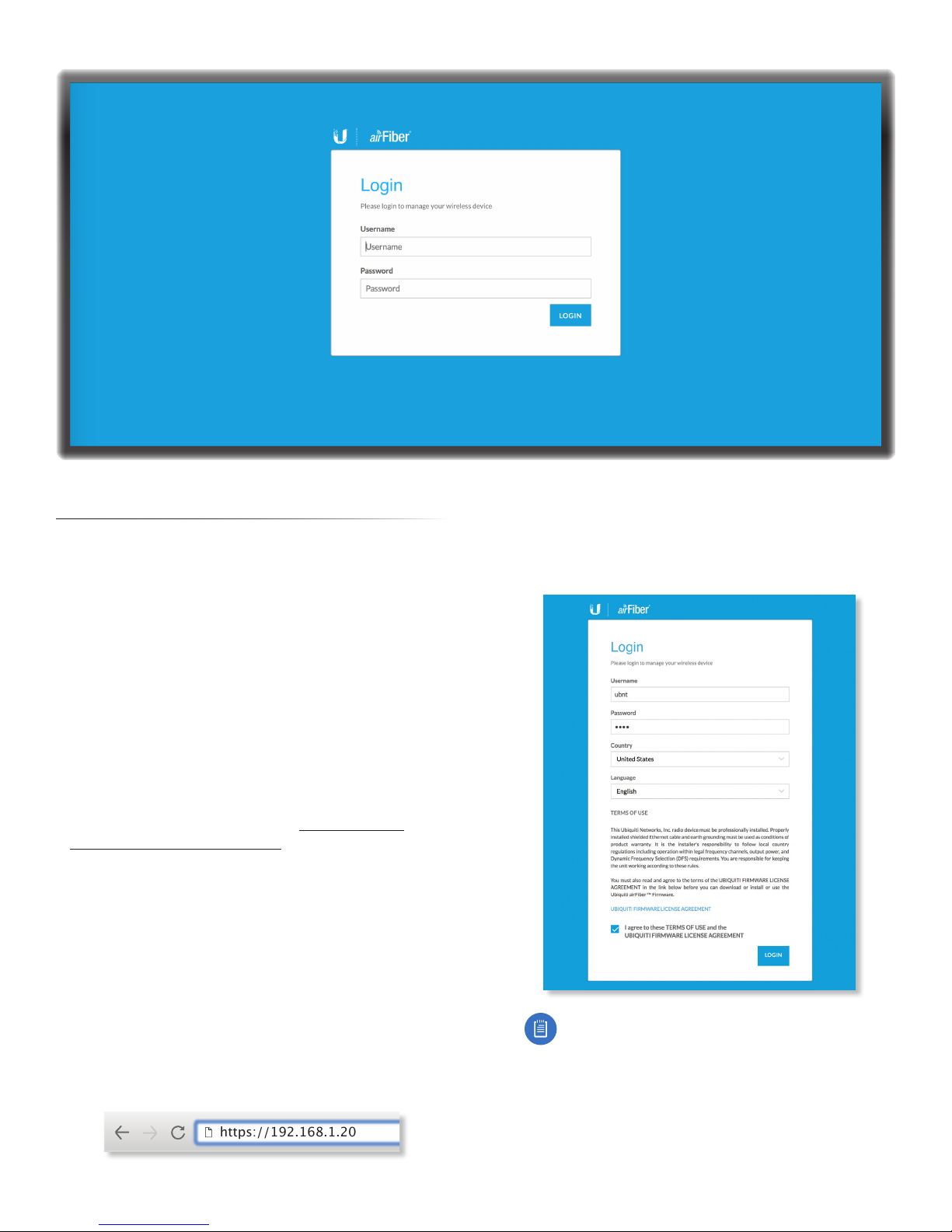
3. Launch your web browser. Type http://192.168.1.20 in
the address field and press enter (PC) or return (Mac).
4. Upon initial login, the Terms of Use appear on the login
screen. Enter ubnt in the Username and Password fields,
and select the appropriate choices from the Country
and Language drop-down lists. Check the box next to
Iagree to these terms of use, and click Login.
Note: U.S. product versions are locked to the U.S.
Country Code to ensure compliance with FCC
regulations.
5. The airFiber Configuration Interface will appear,
allowing you to customize your settings as needed.
https://192.168.1.20
Ubiquiti Networks, Inc.
21
Page 26
Chapter 3: Navigation airFiber AF-24/AF-24HD User Guide
Navigating the Interface
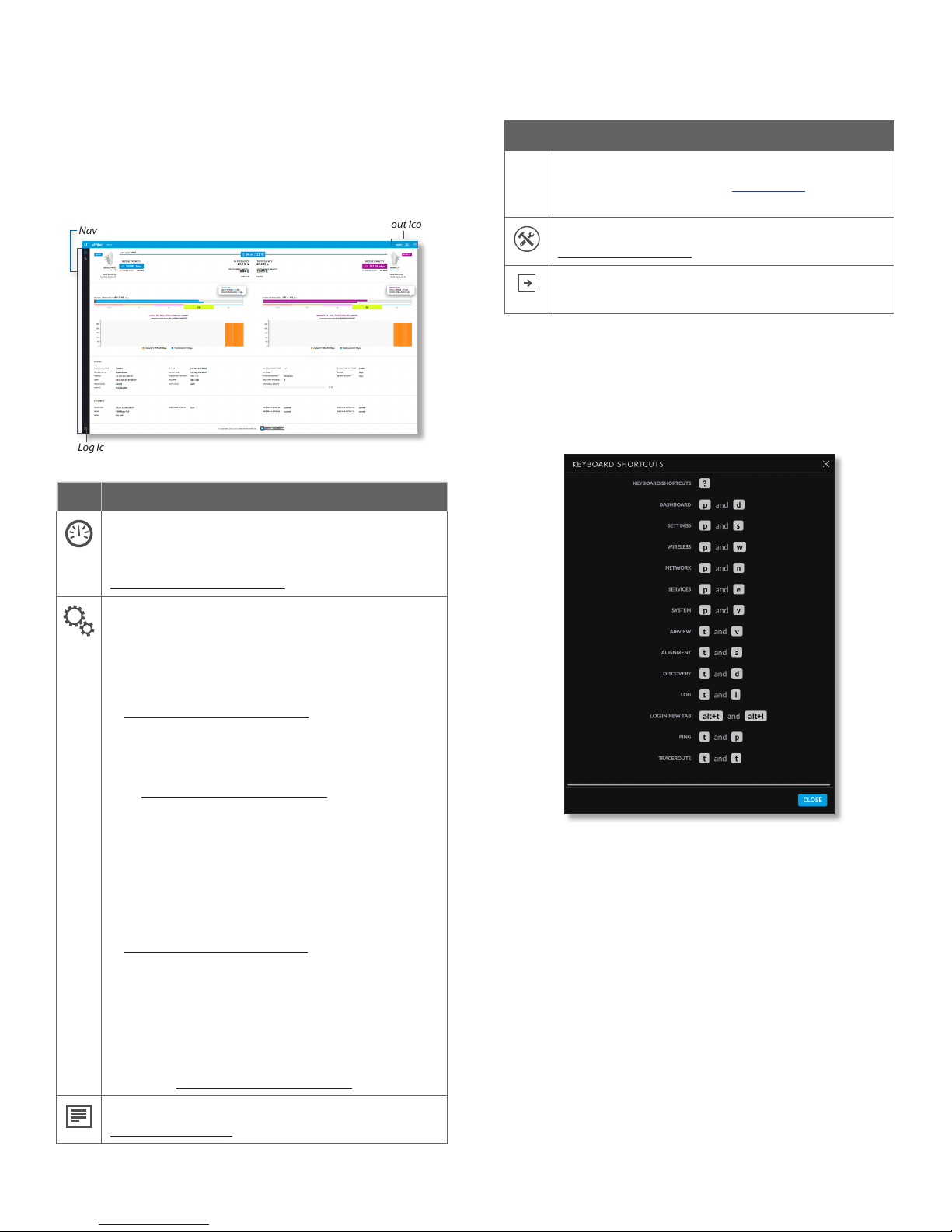
The airFiber Configuration Interface contains two main
pages. Each web-based management page is used to
configure a specific aspect of the AF-24/AF-24HD radio,
and is accessed by clicking its icon in the navigation bar
on the left side of the interface:
Tools and
Navigation Bar
Log Icon
Icon Web-Based Management Page
Displays the Dashboard, with device and link
status, statistics, and network monitoring
and RF performance data. For details, refer to
“Dashboard” on page 25.
Logout Icons
At the lower left and upper right of the window are icons
used to access additional tools and information:
Icon Web-Based Management Page
UNMS
Opens the Ubiquiti Network Management
System (UNMS™) website (unms.com) in a new
browser tab.
Displays the Tools menu. For details, refer to
“Tools” on page 45.
Click this icon to immediately log out of the
airFiber Configuration Interface.
Keyboard Shortcuts
Keyboard shortcuts allow you to access the Configuration
Interface pages, tabs, and tools by pressing a single key or
two keys.
Press ? at any time to display the keyboard shortcut menu.
22
Displays the Settings page with these tabs:
• Wireless Configures the wireless settings,
including wireless mode, link name, channel
bandwidth and frequency, output power,
gain, and wireless security. For details, refer to
“Wireless Tab” on page 29.
• Network Configures the network mode; data
port settings; management port settings; and
Ethernet carrier drop settings. For details, refer
to “Network Tab” on page 33.
• Services Configures system management
services: Bluetooth management, Ping
Watchdog, Simple Network Management
Protocol (SNMP), servers (web, SSH, Telnet),
Network Time Protocol (NTP) client, Dynamic
Domain Name System (DDNS) client, system
log, and device discovery. For details, refer to
“Services Tab” on page 37.
• System Controls system maintenance, such
as firmware updates, device and date settings,
system account settings, location settings,
device maintenance, and configuration
backup. You can also change the language of
the web management interface. For details,
refer to “System Tab” on page 41.
Displays the system log. For details, refer to
“Log” on page 49.
? Displays the list of keyboard shortcuts.
p d Displays the Dashboard.
p s Displays the Settings page.
p w Displays the Wireless tab of the Settings page.
p n Displays the Network tab of the Settings page.
p e Displays the Service tab of the Settings page.
p y Displays the System tab of the Settings page.
t v Displays the airView tool.
t a Displays the Antenna Alignment tool.
t d Displays the Device Discovery tool.
alt+t alt+l Opens the login screen in a new tab.
t p Displays the Ping tool.
t t Displays the Traceroute tool.
Close Click to close the shortcut menu.
Ubiquiti Networks, Inc.
Page 27
Notifications
Pending Changes
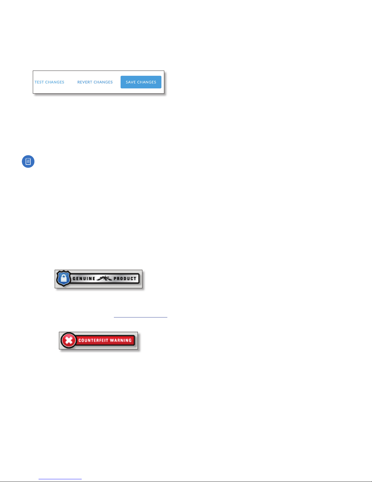
When you make changes to any settings on any page, the
following buttons appear at the bottom of the page:
Use the buttons to perform operations on all unsaved
changes. You have three options:
Test Changes Click Test Changes to try changes without
saving them. You have two options:
• Apply Click Apply to save changes.
• Discard Click Discard to cancel changes.
Note: If you do not click Apply within 180 seconds
(the countdown is displayed), the device times out
and resumes its earlier configuration.
Revert Changes Click Revert Changes to cancel all
pending changes on all pages.
Save Changes Click Save Changes to immediately apply
and save changes.
Chapter 3: NavigationairFiber AF-24/AF-24HD User Guide
Product Verification
The airFiber Configuration Interface will verify whether a
product is genuine or counterfeit.
For a genuine airFiber AF-24, the airFiber Configuration
Interface will display a Genuine Product logo in the lower
left corner of the screen.
For any product that is not an official Ubiquiti product, the
airFiber Configuration Interface will display a counterfeit
warning. Please contact Ubiquiti at [email protected]
regarding this product.
Ubiquiti Networks, Inc.
23
Page 28

airFiber AF-24/AF-24HD User Guide
24
Ubiquiti Networks, Inc.
Page 29
Chapter 4: DashboardairFiber AF-24/AF-24HD User Guide
Chapter 4: Dashboard
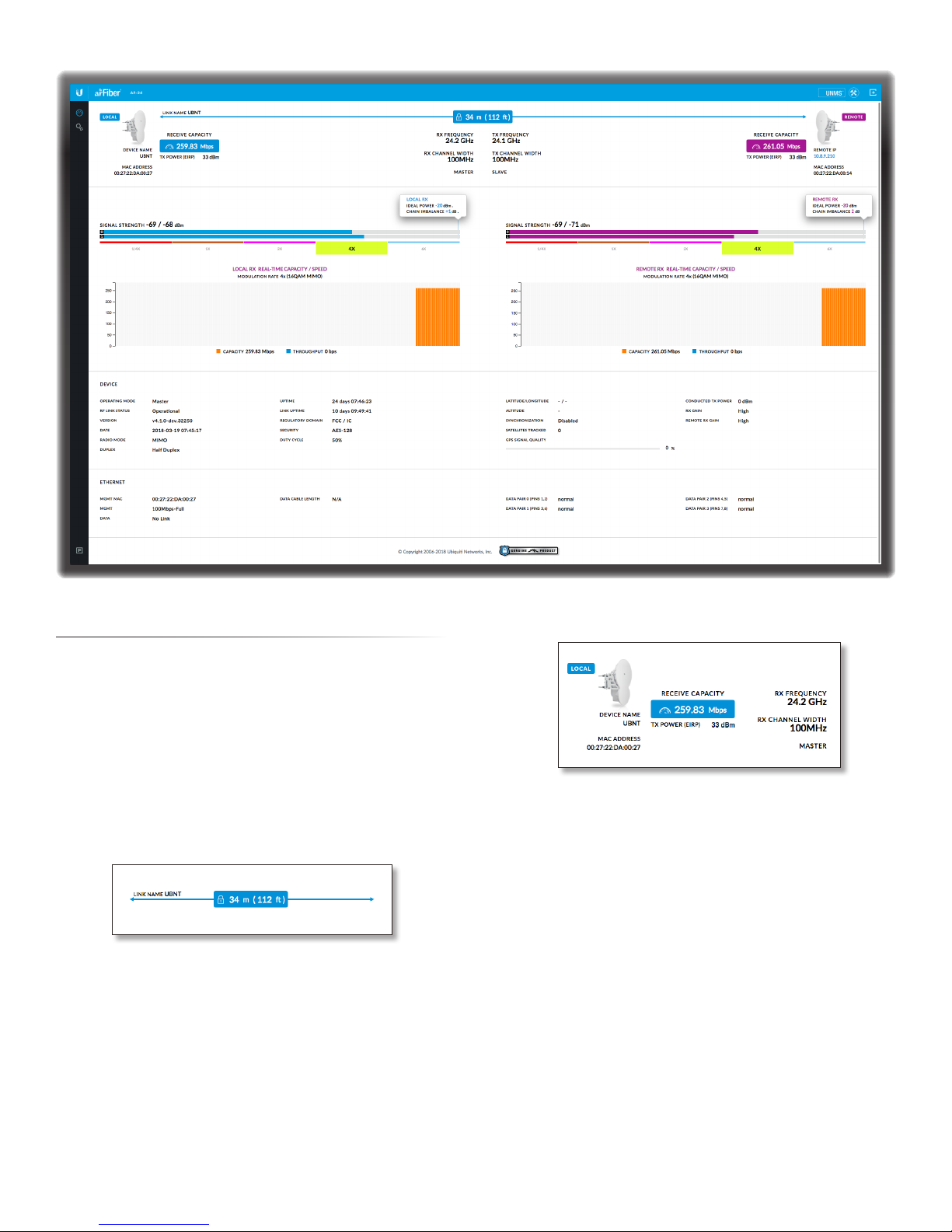
The Dashboard displays a visual summary of the link
status, basic configuration settings, network settings
and information, and traffic statistics. Where applicable,
information is displayed for both the local device (on the
left) and the remote device (on the right).
Link Status
The top section of the Dashboard displays the status of the
link and the local and remote devices as follows:
RF Link
Link Name Displays the name of your link.
(Distance) Displays the distance between the local
and remote radios. The lock icon appears if the link is
connected (no icon is shown if there is no connection).
Local Device
Device Name Displays the local device’s customizable
name or identifier. The Device Name (or host name) is
displayed in registration screens and discovery tools.
MAC Address Displays the local device’s MAC address.
Receive Capacity Displays the local device’s receive
capacity in Mbps.
TX Power EIRP Displays the local device’s current average
transmit output power (in dBm).
RX Frequency Displays the local device’s current receive
frequency.
RX Channel Width Displays the local device’s current
channel bandwidth in MHz.
(Wireless Mode) Displays the mode of the local airFiber
radio: Master or Slave.
Ubiquiti Networks, Inc.
25
Page 30
Chapter 4: Dashboard airFiber AF-24/AF-24HD User Guide
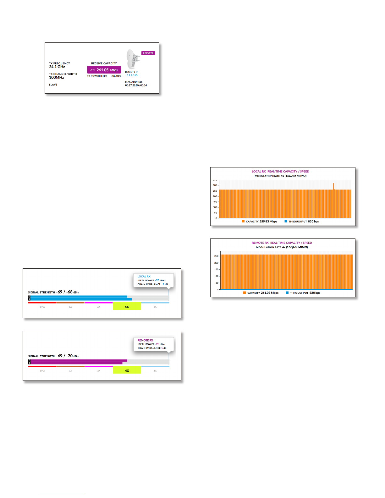
Remote Device
Remote IP Displays the remote device’s IP address.
MAC Address Displays the remote device’s MAC address.
Receive Capacity Displays the remote device’s receive
capacity in Mbps.
TX Power EIRP Displays the remote device’s current
average transmit output power (in dBm).
TX Frequency Displays the remote device’s current
transmit frequency.
TX Channel Width Displays the remote device’s current
channel bandwidth in MHz.
(Wireless Mode) Displays the mode of the remote
airFiber radio: Master or Slave.
Below the signal strength graph, the current modulation
rate is displayed for the local or remote device:
• 6x (64QAM MIMO)
• 4x (16QAM MIMO)
• 2x (QPSK MIMO)
• 1x (QPSK SISO)
• ¼ x (QPSK SISO)
Above the graph, the following are displayed:
• Ideal Power Displays the expected receive power
indBm.
• Chain Imbalance Displays the chain imbalance in dB.
Local/Remote RX Real-Time Capacity / Speed Displays
the capacity and throughput rates for the local and
remote device. Capacity is indicated by the filled area of
the graph; throughput is indicated by the solid line.
Statistics
The next section of the Dashboard displays various
information in graphical form:
Signal Strength xx/yy dBm Displays the actual (xx) and
ideal (yy) power levels in dBm of the received signal for
each chain of the local or remote device.
The actual number indicates the current RX signal
strength. The ideal number is the RX signal strength of a
perfectly aligned link. These two numbers indicate exactly
how many dB out of alignment the system is.
The colored bar indicates the relative signal strength. If the
bar does not span the full width of the graph, your link is
not optimally aimed.
The capacity is the expected maximum rate at which
data can be transmitted over the channel (accounting for
protocol overhead and interference).
The capacity graph displays the potential data traffic on
the DATA port in both graphical and numerical form. The
chart scale and capacity dimension (bps, kbps, Mbps)
change dynamically depending on the mean capacity
value. The statistics are updated automatically.
The throughput graph displays the current data traffic on
the DATA port in both graphical and numerical form. The
chart scale and throughput dimension (bps, kbps, Mbps)
change dynamically depending on the mean throughput
value. The statistics are updated automatically.
26
Ubiquiti Networks, Inc.
Page 31
Chapter 4: DashboardairFiber AF-24/AF-24HD User Guide
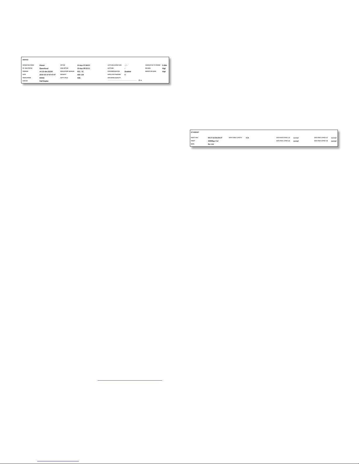
Device Status
The next section of the Dashboard displays additional
status information for the local device.
Operating Mode Displays the mode of the local airFiber
radio: Master, Slave, or Reset.
RF Link Status Displays the status of the airFiber AF-24:
RF Off, Syncing, Beaconing, Registering, Enabling, Listening,
or Operational.
Version Displays the version of the firmware running in
the local device.
Date Displays the current system date and time (the
format is browser and location-dependent). The system
date and time is retrieved from the internet using NTP
(Network Time Protocol). The NTP Client is disabled by
default on the Services page. The device doesn’t have an
internal clock, and the date and time may be inaccurate if
the NTP Client is disabled or the device isn’t connected to
the internet.
Radio Mode Always displays MIMO (SISO mode is not
supported).
Duplex Displays Full Duplex or Half Duplex. Fullduplex
mode allows communication in both directions
simultaneously. Halfduplex mode allows communication
in one direction at a time, alternating between
transmission and reception.
Uptime This is the total time the device has been running
since the latest reboot (when the device was powered up)
or software upgrade. The time is displayed in days, hours,
minutes, and seconds.
Link Uptime Displays the total time the airFiber link has
been continuously operational. The time is displayed in
days, hours, minutes, and seconds.
Regulatory Domain Displays the regulatory domain
(FCC/ICC, ETSI, or Other), as determined by country
selection.
Security AES-128 is enabled at all times.
Duty Cycle Displays the duty cycle.
Latitude/Longitude Based on GPS tracking, reports the
local device’s current latitude and longitude. Clicking
the link opens the reported latitude and longitude in a
browser using Google Maps™ (http://maps.google.com).
Altitude Based on GPS tracking, reports the local device’s
current altitude relative to sea level.
Synchronization airFiber uses GPS to synchronize the
timing of its transmissions. By default, this option is
Disabled.
Satellites Tracked Displays the number of satellites
tracked by the GPS receiver.
GPS Signal Quality Displays Global Positioning System
(GPS) signal quality as a percentage value on a scale of
0-100%.
Conducted TX Power Displays the conducted transmit
power out of the radio before any antenna gain.
RX Gain Displays the gain for the RX antenna of the local
AF-24 device: High or Low.
Remote RX Gain Displays the gain for the RX antenna of
the remote AF-24 device: High or Low.
Ethernet Connection Status
Mgmt MAC Displays the MAC address of the Config port.
Mgmt Displays the speed and duplex of the Config port.
Data Displays the speed and duplex of the Data port.
Data Cable Length Displays the length of the Ethernet
data cable attached to the local radio. This is displayed
only for cables longer than 20m.
Data Pair 0 (Pins 1, 2) If the cable is functioning properly,
this field displays the SNR of the twisted pair. If the cable
has a fault, the field displays the fault (Open or Short) and
the distance at which the fault has occurred. If the remote
port is administratively shut down, Normal is displayed.
Data Pair 1 (Pins 3, 6) If the cable is functioning properly,
this field displays the SNR of the twisted pair. If the cable
has a fault, the field displays the fault (Open or Short) and
the distance at which the fault has occurred. If the remote
port is administratively shut down, Normal is displayed.
Data Pair 2 (Pins 4, 5) If the cable is functioning properly,
this field displays the SNR of the twisted pair. If the cable
has a fault, the field displays the fault (Open or Short) and
the distance at which the fault has occurred. If the remote
port is administratively shut down, Normal is displayed.
Data Pair 3 (Pins 7, 8) If the cable is functioning properly,
this field displays the SNR of the twisted pair. If the cable
has a fault, the field displays the fault (Open or Short) and
the distance at which the fault has occurred. If the remote
port is administratively shut down, Normal is displayed.
Ubiquiti Networks, Inc.
27
Page 32

Chapter 4: Dashboard airFiber AF-24/AF-24HD User Guide
28
Ubiquiti Networks, Inc.
Page 33
Chapter 5: Wireless TabairFiber AF-24/AF-24HD User Guide
SlaveMaster
SlaveMaster
Chapter 5: Wireless Tab
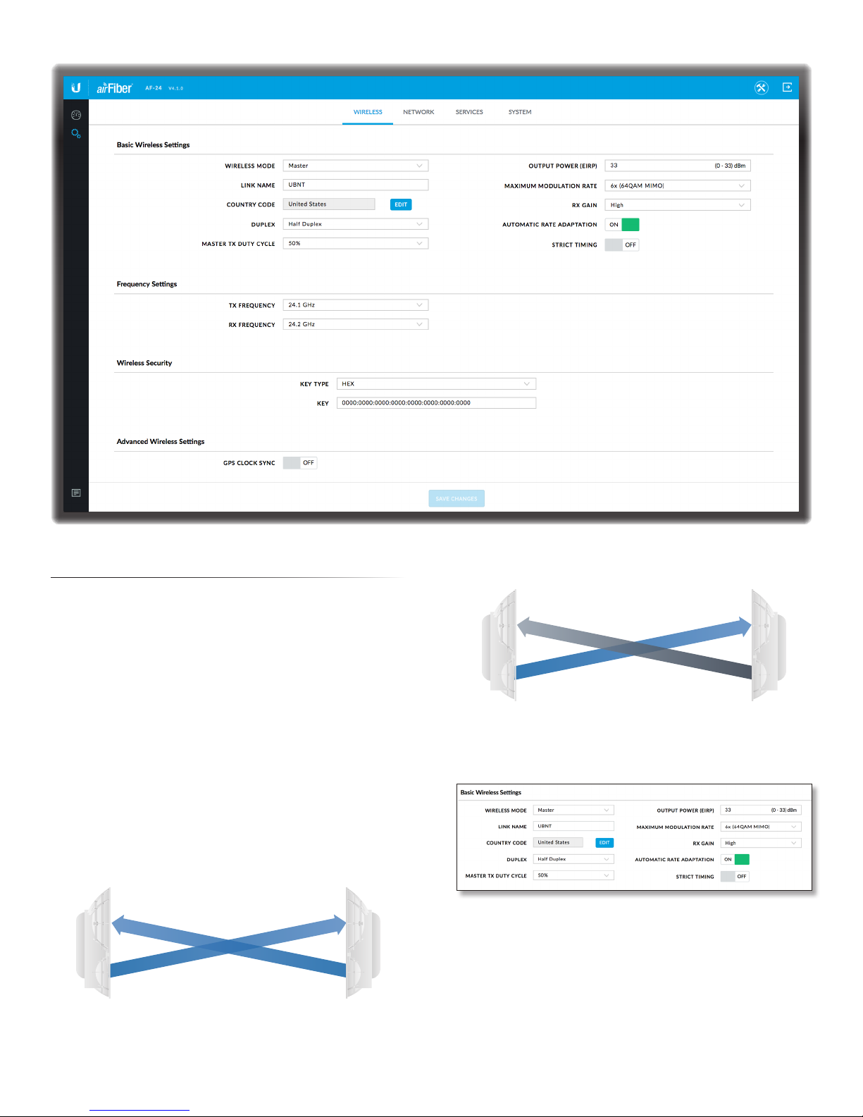
The Wireless tab contains everything needed to set up
the wireless part of the link. This includes wireless mode,
link name, frequencies, output power, speed, gain, and
wireless security.
Write down the settings you configure on the Wireless tab.
You will need to enter the same settings on the airFiber
AF-24 at the other end of your PtP link. The exceptions are
as follows:
• Wireless Mode Configure one airFiber AF-24 as the
Master and the other as the Slave.
• TX and RX Frequencies The TX Frequency on the
Master should be used as the RX Frequency on the Slave,
and vice versa.
For Half Duplex mode (default), the TX and RX Frequencies
can be the same or different frequencies, in response to
local interference.
RX
Frequency A
TX
Half-Duplex Diagram
RX
Frequency A
TX
For Full Duplex mode, the TX and RX Frequencies should be
different.
RX
Frequency A
TX
Full-Duplex Diagram
RX
Frequency B
TX
Basic Wireless Settings
In this section, configure the basic wireless settings, such
as wireless mode, link name, country code, duplex, duty
cycle, output power, modulation rate, gain, and rate
adaptation.
Wireless Mode By default, the Wireless Mode is Slave. You
must configure one airFiber AF-24 to Master because each
PtP link must have one Master.
Link Name Enter a name for your PtP link.
Ubiquiti Networks, Inc.
29
Page 34
Chapter 5: Wireless Tab airFiber AF-24/AF-24HD User Guide
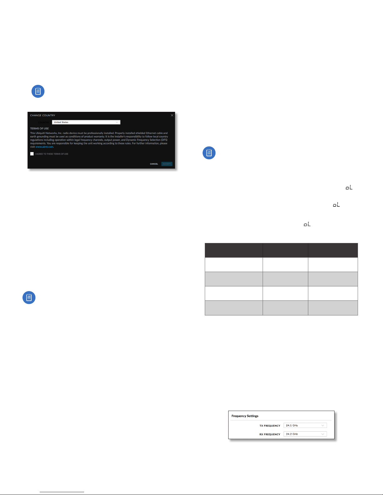
Country Code Each country has its own power level and
frequency regulations. To ensure the airFiber AF-24 operates
under the necessary regulatory compliance rules, you must
select the country where your device will be used. The
frequency settings and output power limits will be tuned
according to the regulations of the selected country.
• Edit To select a new country, click Edit.
Note: U.S. product versions are locked to the U.S.
Country Code to ensure compliance with FCC
regulations.
- Change Country Select the new country.
- I agree to these terms of use Check this box; you
must agree to the Terms of Use to use the product.
- Accept Saves your change.
- Cancel Discards your change.
Duplex Select Half Duplex or Full Duplex. Half-duplex
operation provides more frequency planning options at
the cost of higher latency and throughput. (Half-duplex
mode allows communication in one direction at a
time, alternating between transmission and reception.)
Full-duplex operation provides the highest throughput
and lowest latency; however, you have fewer frequency
management options. (Full-duplex mode allows
communication in both directions simultaneously.)
Note: For Half Duplex mode (default), the TX and RX
Frequencies on the same airFiber AF-24 can be the
same or different to suit local interference. For Full
Duplex mode, the TX and RX Frequencies on the same
airFiber AF-24 should be different.
Master TX Duty Cycle Used to select the duty cycle of the
Master transmit link: 25%, 33%, 50%, 67%, or 75%.
Output Power (EIRP) Defines the maximum average
transmit output power (in dBm) of the airFiber AF-24.
To specify the output power, manually enter the output
power value. The transmit power level maximum is limited
according to country regulations.
Maximum Modulation Rate / Modulation Rate Higher
modulations allow greater throughput but generally
require stronger RF signals and a higher Signal-to-Noise
Ratio (SNR). By default, Automatic Rate Adaptation is
enabled, and Maximum Modulation Rate is displayed.
This allows the airFiber AF-24 to automatically adjust the
modulation rate to changing RF signal conditions. Under
certain conditions, you may prefer to lock the Maximum
Modulation Rate to a lower setting to improve link
performance.
When Automatic Rate Adaptation is disabled, Modulation
Rate is displayed. Lock the Modulation Rate to the setting
of your choice.
Select one of the available modulation rates:
• 8x (256QAM MIMO) (AF-24HD only)
• 6x (64QAM MIMO)
• 4x (16QAM MIMO)
• 2x (QPSK MIMO)
• 1x (QPSK SISO)
• ¼x (QPSK SISO)
RX Gain Select the appropriate gain for your RX antenna:
High (default) or Low. If the link is very short or being
tested, select Low, so your signal does not get distorted.
Note: Minimum link distance is approximately 100 m
(328 ft).
For links between 100 m (328 ft) and 800 m (2,625 ft):
• Target -40 dBm.
• Decrease RX Gain to overcome overload condition ( ).
• For short ranges or strong signal conditions, adjust the
power to be 3-5 dB below overload condition ( ).
• Decrease RX Gain first.
• Never mitigate overload condition ( ) by misaligning
antennas.
Link Distance RX Gain Setting
d > 1 km
(d > 3,281 ft)
0.5 km < d < 1 km
(1,640 ft < d < 3,281 ft)
0.25 km < d < 0.5 km
(820 ft < d < 1,640 ft)
0.1 km < d < 0.25 km
(328 ft < d < 820 ft)
High > 25 dBm
Low 19-25 dBm
Low 12-18 dBm
Low 3-11 dBm
Approximate
TX Power Setting
Automatic Rate Adaptation Set this to On to enable
automatic adaptation of the Maximum Modulation Rate.
Set this to Off to manually specify the Modulation Rate.
Strict Timing Enabling this shortens the TX window
slightly (reduces capacity) to compensate for half duplex
co-located links where the distance covered by each
differs greatly. This can be used to eliminate potential colocation interference. This should only need to be enabled
when co-location interference is suspected.
Frequency Settings
This section allows you to configure the transmit and
receive frequencies for the local AF-24 device.
30
Ubiquiti Networks, Inc.
Page 35
TX Frequency Select a transmit frequency.
Note: The TX Frequency on the Master should be
used as the RX Frequency on the Slave, and vice versa.
RX Frequency Select a receive frequency.
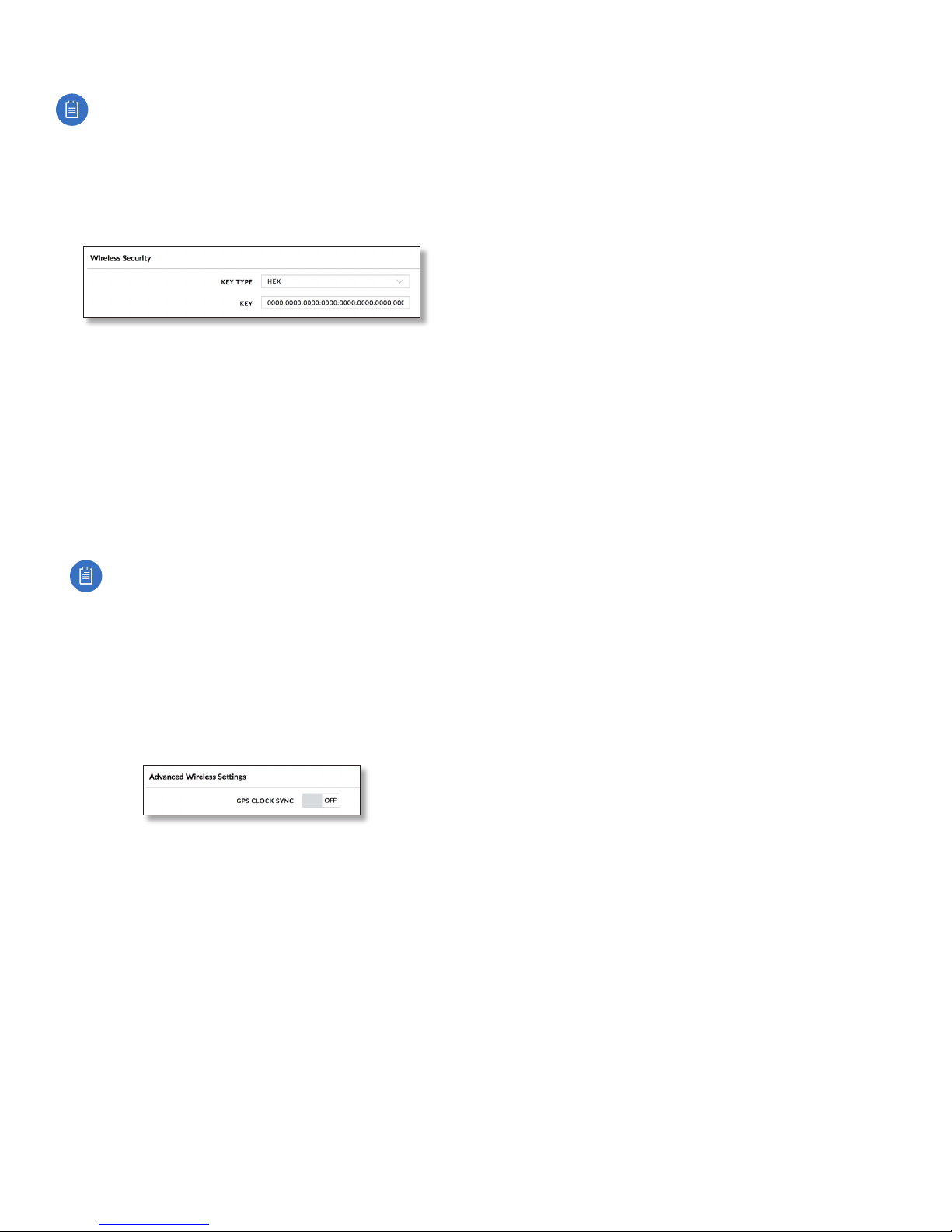
Wireless Security
airFiber uses 128-bit, AES (Advanced Encryption Standard)
encryption at all times.
Key Type Specifies the character format.
• HEX By default, this option uses hexadecimal
characters. 0-9, A-F, or a-f are valid characters.
• ASCII ASCII uses the standard English alphabet and
numeric characters (0-9, A-Z, or a-z).
Key Select the format of the MAC address.
• HEX Enter 16bytes (eight, 16-bit HEX values). You can
omit zeroes and use colons, similar to the IPv6 format.
The default is:
0000:0000:0000:0000:0000:0000:0000:0000.
Chapter 5: Wireless TabairFiber AF-24/AF-24HD User Guide
Note: The airFiber Configuration Interface
supports IPv6 formats excluding dotted quad and
“::” (double-colon) notation.
• ASCII Enter a combination of alphanumeric characters.
Using 128-bit, SHA1 (Secure Hash Algorithm 1), airFiber
AF-24 hashes the ASCII key to create a 128-bit key for AES.
Advanced Wireless Settings
This section allows you to configure advanced wireless
settings such as GPS clock synchronization.
GPS Clock Sync The airFiber AF-24 uses GPS to
synchronize the timing of its transmissions. By default, this
option is disabled.
Ubiquiti Networks, Inc.
31
Page 36

Chapter 5: Wireless Tab airFiber AF-24/AF-24HD User Guide
32
Ubiquiti Networks, Inc.
Page 37
Chapter 6: Network Tab airFiber AF-24/AF-24HD User Guide
Chapter 6: Network Tab
The Network tab allows you to configure settings for the
management network. There are two ways to access the
airFiber Configuration Interface:
• Config Port Enabled by default. Use a direct connection
to the Config port for out-of-band management.
• In-Band Management Enabled by default. In-band
management is available through the local Data port or
the Data port at the other end of the link.
The Config port and in-band management share the
default IP address of 192.168.1.20.
Management Network Settings
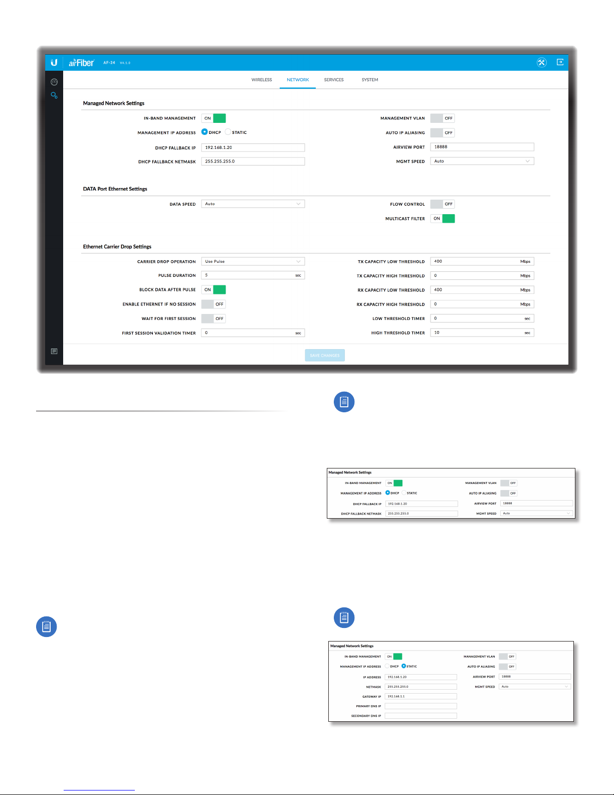
In-Band Management Enabled by default. In-band
management is available through the local Data port or the
Data port at the other end of the link.
Note: If In-Band Management is enabled, ensure that
each airFiber radio of a link has a unique IP Address. If
the airFiber radios use the same IP Address, then you
may lose access via the Data ports.
Management IP Address The AF-24 can use a static IP
address or obtain an IP address from its DHCP server.
• DHCP Keep the default, DHCP, to use DHCP reservation
on your router to assign a unique IP Address. The local
DHCP server function of the router assigns a dynamic
IP address, gateway IP address, and DNS address to the
airFiber AF-24.
Ubiquiti Networks, Inc.
Note: If you do not know the IP address, the only
way to manage the airFiber AF-24 is to reset it
to its factory default settings. (Press and hold
the Reset button for more than five seconds.)
Its default Management IP Address is reset to
192.168.1.20.
- DHCP Fallback IP Specify the IP address the AF-24
should use if a DHCP server is not found.
- DHCP Fallback Netmask Specify the netmask the
AF-24 should use if a DHCP server is not found.
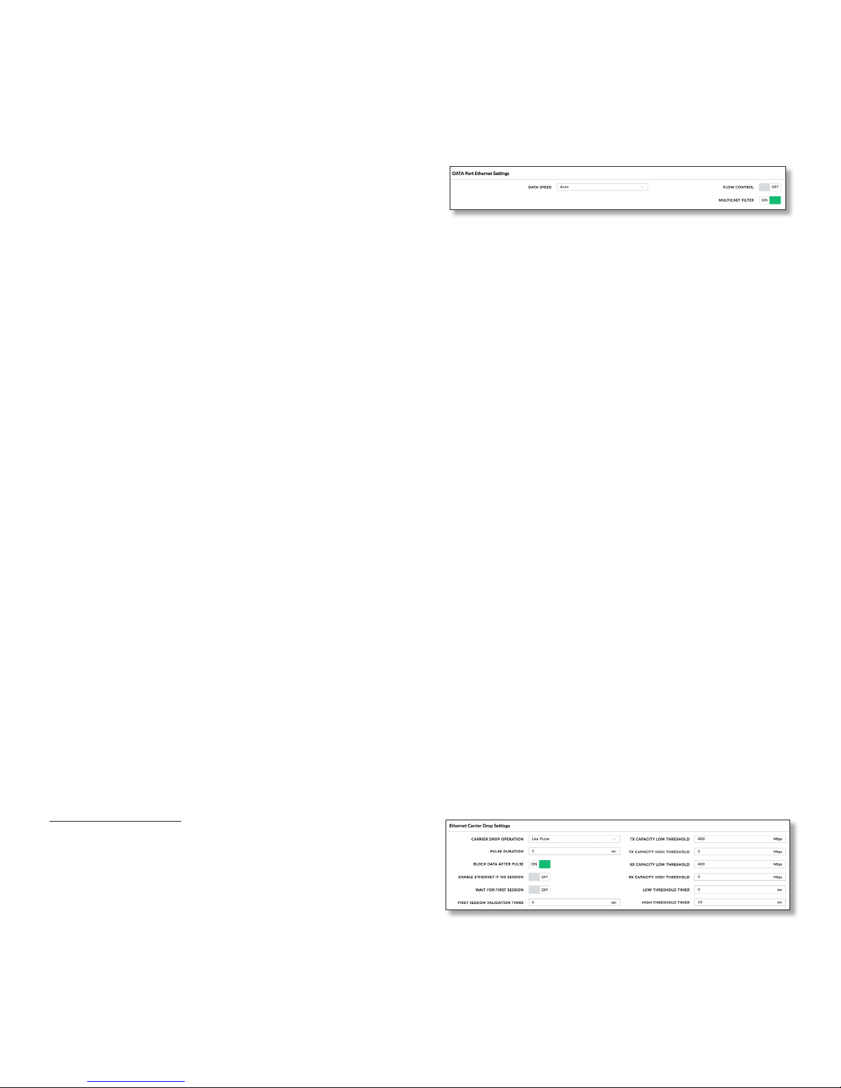
• Static Assign static IP settings to the airFiber AF-24.
Note: IP settings should be consistent with the
address space of the AF-24’s network segment.
- IP Address Specify the IP address of the AF-24. This IP
will be used for device management purposes.
33
Page 38
Chapter 6: Network Tab airFiber AF-24/AF-24HD User Guide
- Netmask When the netmask is expanded into its
binary form, it provides a mapping to define which
portions of the IP address range are used for the
network devices and which portions are used for host
devices. The netmask defines the address space of the
airFiber AF-24’s network segment. The 255.255.255.0
(or “/24”) netmask is commonly used on many Class C
IP networks.
- Gateway IP Typically, this is the IP address of the host
router, which provides the point of connection to the
internet. This can be a DSL modem, cable modem, or
WISP gateway router. The airFiber AF-24 directs data
packets to the gateway if the destination host is not
within the local network.
- Primary DNS IP Specify the IP address of the primary
DNS (Domain Name System) server.
- Secondary DNS IP Specify the IP address of the
secondary DNS server. This entry is optional and used
only if the primary DNS server is not responding.
Management VLAN If enabled, automatically creates a
management Virtual Local Area Network (VLAN).
• VLAN ID (Available if Management VLAN is enabled.)
Enter a unique VLAN ID from 2 to 4094.
Auto IP Aliasing If enabled, automatically generates an
IP address for the corresponding WLAN/LAN interface.
The generated IP address is a unique Class B IP address
from the 169.254.X.Y range (netmask 255.255.0.0), which
is intended for use within the same network segment
only. The Auto IP always starts with 169.254.X.Y, with X
and Y as the last two octets from the MAC address of
the airFiber AF-24. For example, if the MAC address is
00:15:6D:A3:04:FB, then the generated unique Auto IP will
be 169.254.4.251. (The hexadecimal value, FB, converts to
the decimal value, 251.)
The Auto IP Aliasing setting can be useful because you
can still access and manage devices even if you lose,
misconfigure, or forget their IP addresses. Because an
Auto IP address is based on the last two octets of the MAC
address, you can determine the IP address of a device if
you know its MAC address.
airView Port The port number associated with the
airView spectrum analyzer tool. The default value is 18888.
For detailed information on the airView tool, refer to
“airView” on page 47.
Mgmt Speed This is the speed of the Management
port. By default, the option is Auto. The airFiberX radio
automatically negotiates transmission parameters, such as
speed and duplex, with its counterpart. In this process, the
networked devices first share their capabilities and then
choose the fastest transmission mode they both support.
To manually specify the maximum transmission link
speed and duplex mode, select one of the following
options: 100 Mbps-Full, 100Mbps-Half, 10 Mbps-Full,
or 10Mbps-Half. If you are running extra long Ethernet
cables, a link speed of 10Mbps could help to achieve
better stability.
34
Full-duplex mode allows communication in both
directions simultaneously. Half-duplex mode allows
communication in one direction at a time, alternating
between transmission and reception.
Data Port Ethernet Settings
Data Speed This is the speed of the Data port.
Thedefault is Auto, which allows the radio to operate at a
speed of 1Gbps. The AF-24 radio automatically negotiates
transmission parameters, such as speed and duplex, with
its counterpart. In this process, the networked devices
first share their capabilities and then choose the fastest
transmission mode they both support.
To manually specify the maximum transmission link
speed and duplex mode, select one of the following
options: 100 Mbps-Full, 100Mbps-Half, 10Mbps-Full, or
10Mbps-Half.
Full-duplex mode allows communication in both
directions simultaneously. Half-duplex mode allows
communication in one direction at a time, alternating
between transmission and reception.
Flow Control If enabled, the AF-24 radio generates and
responds to Ethernet layer PAUSE frames. The AF-24 radio
regulates inbound traffic from the customer’s network to
avoid buffer overflows within the AF-24 radio. Flow control
has the effect of controlling the inter-packet spacing of
packets headed into the airFiber Data interface.
Multicast Filter If enabled, the filter blocks multicast
traffic from overloading the CPU when in-band
management is enabled. This allows the AF-24 radio to
be managed in-band when the customer’s network is
carrying large volumes of multicast traffic, such as IPTV.
The filter does not block multicast traffic going over the
radio; it simply blocks it from reaching the AF-24 radio’s
management interface CPU.
Ethernet Carrier Drop Settings
The Ethernet Carrrier Drop settings are used to control
failover switching between the primary and backup link in
response to capacity loss due to rain.
Carrier Drop Operation This setting is used to control
the Ethernet Carrier Drop feature. Settings are: Disabled,
Enabled, and Use Pulse. The default is Disabled.
Use Pulse and Enabled are the two different methods used
to signal to the failover mechanism that it should switch to
the backup link:
Ubiquiti Networks, Inc.
Page 39

• Use Pulse The LAN link is toggled off.
• Enabled The LAN link will be turned off and left off.
Pulse Duration (Available if Carrier Drop Operation is set
to Use Pulse.) This is the length of time that the LAN link
remains down to trigger failover. The default is 5 seconds.
Block Data After Pulse (Available if Carrier Drop
Operation is set to Use Pulse.) Enable this option to stop
data from passing through the link when it is experiencing
loss of capacity. The default is Off.
Enable Ethernet If No Session Enable this option to
allow management data (such as GUI, SNMP, and ping
packets) to pass, even if the Block Data After Pulse option is
enabled. The default is Off.
Wait for First Session Enable this option to cause the
system to wait until the Ethernet link has been successfully
established following a power cycle, to keep the link
from being dropped due to the throughput being below
threshold. The default is Off.
First Session Validation Timer Use this setting to specify
how long to wait before triggering a link failure due to
insufficient threshold capacity following a power cycle.
The default is 0 seconds.
TX Capacity Low Threshold This is the minimum
allowable TX capacity; if the TX capacity goes below this
threshold, the Ethernet link will be dropped. The default is
0 Mbps.
TX Capacity High Threshold This is the TX capacity
required before a dropped link can be declared to be
operational again. The Ethernet link will remain down
until the TX capacity reaches this threshold. The default
is 0Mbps. This setting should be greater than the TX
Capacity Low Threshold to avoid flutter and multiple OSPF
convergences.
RX Capacity Low Threshold This is the minimum
allowable RX capacity; if the RX capacity goes below this
threshold, the Ethernet link will be dropped. The default is
0 Mbps.
RX Capacity High Threshold This is the RX capacity
required before a dropped link can be declared to be
operational again. The Ethernet link will remain down
until the RX capacity reaches this threshold. The default
is 0Mbps. This setting should be greater than the RX
Capacity Low Threshold to avoid flutter and multiple OSPF
convergences.
Low Threshold Timer This is the number of continuous
seconds that the radio must remain under the minimum
TX or RX capacity threshold before the link is dropped. If
set to 0, then as soon as capacity drops below a set limit,
the Ethernet link will be dropped. The default is 0 seconds.
High Threshold Timer This is the number of continuous
seconds that the radio must remain above the maximum
TX or RX capacity threshold before the link is declared
operational again. The default is 0 seconds.
Chapter 6: Network Tab airFiber AF-24/AF-24HD User Guide
Ubiquiti Networks, Inc.
35
Page 40

airFiber AF-24/AF-24HD User Guide
36
Ubiquiti Networks, Inc.
Page 41
Chapter 7: Services Tab airFiber AF-24/AF-24HD User Guide
Chapter 7: Services Tab
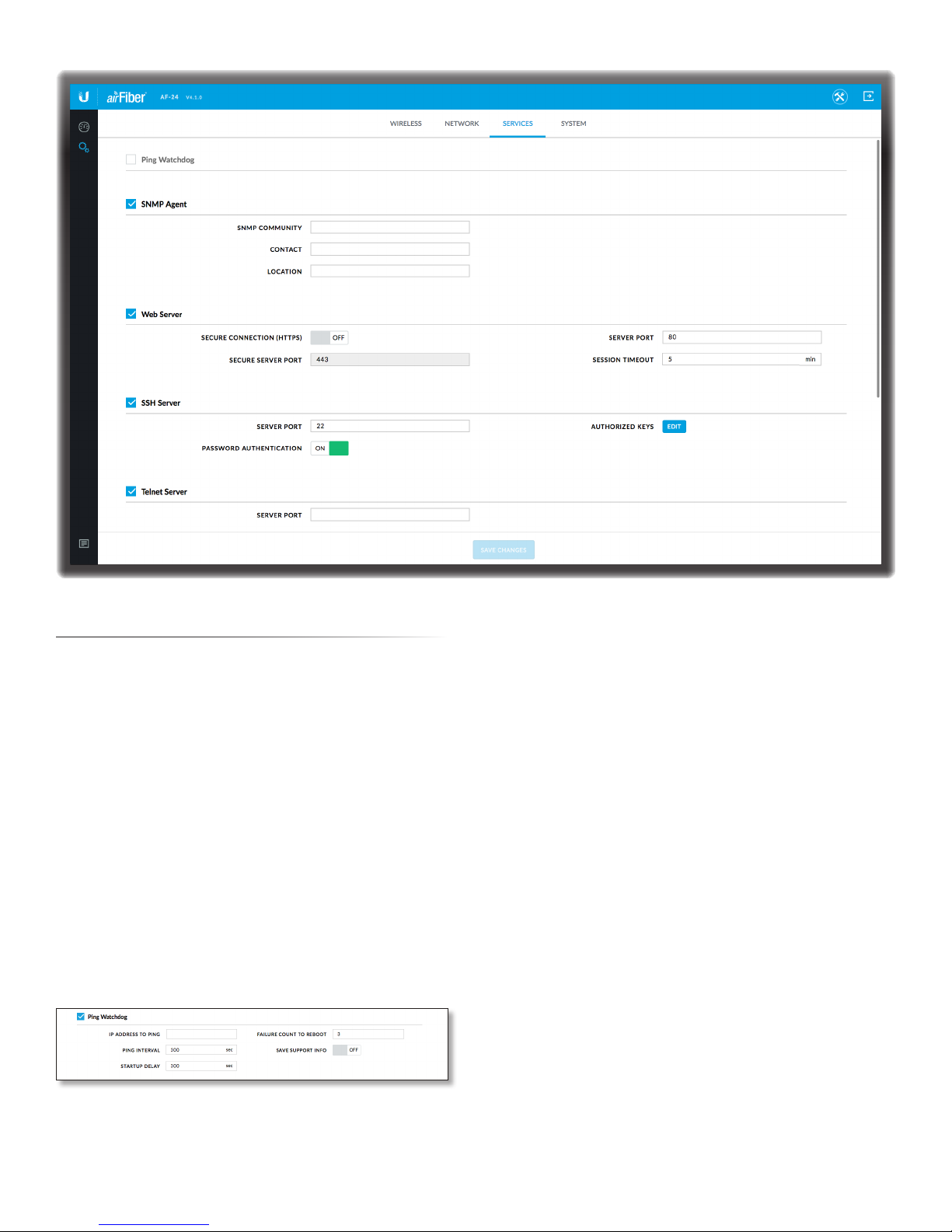
The Services tab configures system management services:
Ping Watchdog, SNMP Agent, Web Server, SSH Server, Telnet
Server, NTP Client, Dynamic DNS, System Log, and Device
Discovery.
Ping Watchdog
Ping Watchdog sets the airFiber AF-24 to continuously
ping a user-defined IP address (it can be the internet
gateway, for example). If it is unable to ping under the
user-defined constraints, then the airFiber AF-24 will
automatically reboot. This option creates a kind of
“fail-proof” mechanism.
Ping Watchdog is dedicated to continuous monitoring of
the specific connection to the remote host using the Ping
tool. The Ping tool works by sending ICMP echo request
packets to the target host and listening for ICMP echo
response replies. If the defined number of replies is not
received, the tool reboots the airFiber AF-24.
Ping Watchdog Enables use of Ping Watchdog.
• IP Address To Ping Specify the IP address of the target
host to be monitored by Ping Watchdog.
• Ping Interval Specify the time interval (in seconds)
between the ICMP echo requests that are sent by Ping
Watchdog. The default value is 300 seconds.
• Startup Delay Specify the initial time delay (in seconds)
until the first ICMP echo requests are sent by Ping
Watchdog. The default value is 300 seconds.
The Startup Delay value should be at least 60 seconds
as the network interface and wireless connection
initialization takes a considerable amount of time if the
airFiber AF-24 is rebooted.
• Failure Count to Reboot Specify the number of ICMP
echo response replies. If the specified number of ICMP
echo response packets is not received continuously,
Ping Watchdog will reboot the airFiber AF-24. The
default value is 3.
• Save Support Info This generates a support
information file.
SNMP Agent
Simple Network Monitor Protocol (SNMP) is an
application layer protocol that facilitates the exchange
of management information between network
devices. Network administrators use SNMP to monitor
network-attached devices for issues that warrant
attention.
Ubiquiti Networks, Inc.
37
Page 42
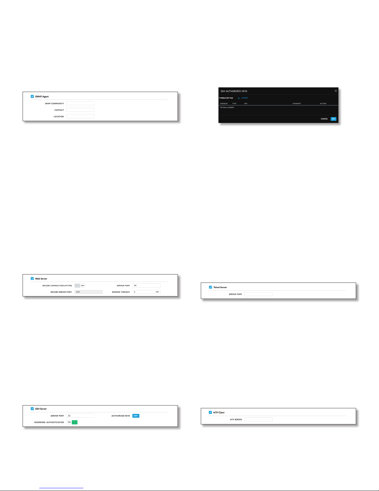
Chapter 7: Services Tab airFiber AF-24/AF-24HD User Guide
The airFiber AF-24 contains an SNMP Agent, which does
the following:
• Provides an interface for device monitoring using SNMP
• Communicates with SNMP management applications
for network provisioning
• Allows network administrators to monitor network
performance and troubleshoot network problems
For the purpose of equipment identification, configure the
SNMP Agent with contact and location information:
SNMP Agent Enables the SNMP Agent.
• SNMP Community Specify the SNMP community
string. It is required to authenticate access to
Management Information Base (MIB) objects and
functions as an embedded password. The airFiber AF-24
also supports a read-only community string; authorized
management stations have read access to all the objects
in the MIB except the community strings, but do not
have write access. The airFiber AF-24 supports SNMP v1.
The default SNMP Community is public.
• Contact Specify the contact who should be notified in
case of emergency.
• Location Specify the physical location of the airFiber
AF-24.
Web Server
• Password Authentication If enabled, you must
authenticate using administrator credentials to
grant SSH access to the airFiber AF-24; otherwise, an
authorized key is required.
• Authorized Keys Click Edit to import a public key file
for SSH access to the airFiber AF-24 instead of using an
admin password.
- Upload Click Upload to locate the new key file. Select
the file and click Open.
- Enabled Enables the specific key. All the added keys
are saved in the system configuration file; however,
only the enabled keys are active on the airFiber AF-24.
- Type Displays the type of key.
- Key Displays the key.
- Comment You can enter a brief description of the key.
- Action You have the following options:
• Add Adds a public key file.
• Edit Make changes to a public key file. Click Save to
save your changes.
• Del Deletes a public key file.
- Ok Saves your changes.
- Cancel Discards your changes.
Telnet Server
The following Web Server parameters can be set:
Secure Connection (HTTPS) If enabled, the Web Server
uses secure HTTPS mode.
• Secure Server Port If secure HTTPS mode is used,
specify the TCP/IP port of the Web Server.
Server Port If HTTP mode is used, specify the TCP/IP port
of the Web Server.
Session Timeout Specifies the maximum timeout before
the session expires. Once a session expires, you must log
in again using the username and password.
SSH Server
The following SSH Server parameters can be set:
SSH Server Enables SSH access to the airFiber AF-24.
• Server Port Specify the TCP/IP port of the SSH Server.
38
The following Telnet Server parameters can be set:
Telnet Server This option activates Telnet access to the
airFiber AF-24.
• Server Port Specify the TCP/IP port of the Telnet Server.
NTP Client
Network Time Protocol (NTP) is a protocol for
synchronizing the clocks of computer systems over
packet-switched, variable-latency data networks. You can
use it to set the system time on the airFiber AF-24. If the
Log option is enabled, then the system time is reported
next to every log entry that registers a system event.
NTP Client Enables the airFiber AF-24 to obtain the
system time from a time server on the internet.
• NTP Server Specify the IP address or domain name of
the NTP server.
Ubiquiti Networks, Inc.
Page 43
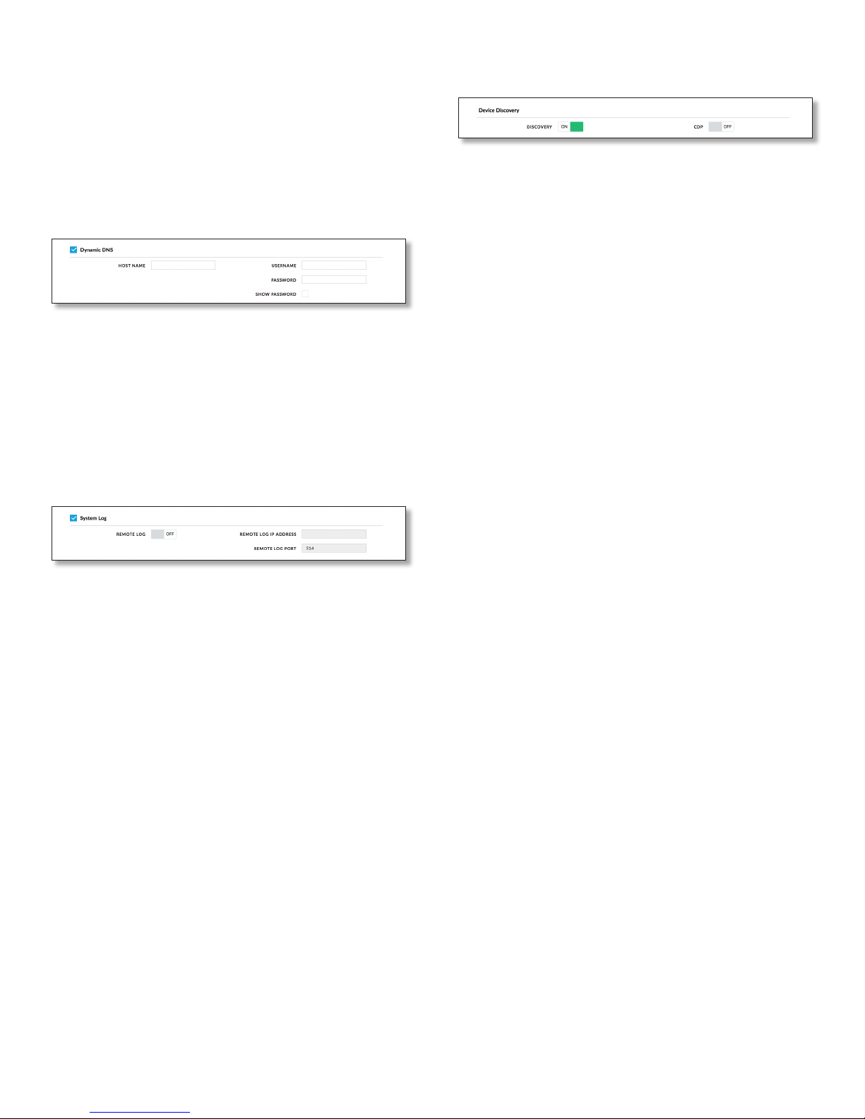
Chapter 7: Services Tab airFiber AF-24/AF-24HD User Guide
Dynamic DNS
Domain Name System (DNS) translates domain names
to IP addresses; Each DNS server on the internet holds
these mappings in its respective DNS database. Dynamic
Domain Name System (DDNS) is a network service that
notifies the DNS server in real time of any changes in the
airFiber AF-24’s IP settings. Even if the airFiber AF-24’s IP
address changes, you can still access the airFiber AF-24
through its domain name.
Dynamic DNS If enabled, the airFiber AF-24 allows
communications with the DDNS server.
• Host Name Enter the host name of the DDNS server.
• Username Enter the user name of the DDNS account.
• Password Enter the password of the DDNS account.
• Show Check the box to display the password
characters.
System Log
Device Discovery
Discovery Enables device discovery, so the airFiber AF-24
can be discovered by other Ubiquiti devices through the
Discovery tool.
CDP Enables Cisco Discovery Protocol (CDP)
communications, so the airFiber AF-24 can send out CDP
packets to share its information.
System Log This option enables the registration routine
of system log (syslog) messages. By default it is disabled.
• Remote Log Enables the syslog remote sending
function. System log messages are sent to a remote
server, which is specified in the Remote Log IP Address
and Remote Log Port fields.
- Remote Log IP Address The host IP address that
receives syslog messages. Properly configure the
remote host to receive syslog protocol messages.
- Remote Log Port The TCP/IP port that receives syslog
messages. 514 is the default port for the commonly
used system message logging utilities.
Every logged message contains at least a system time and
host name. Usually a specific service name that generates
the system event is also specified within the message.
Messages from different services have different contexts
and different levels of detail. Usually error, warning, or
informational system service messages are reported;
however, more detailed debug level messages can also
be reported. The more detailed the system messages
reported, the greater the volume of log messages
generated.
Ubiquiti Networks, Inc.
39
Page 44

Chapter 7: Services Tab airFiber AF-24/AF-24HD User Guide
40
Ubiquiti Networks, Inc.
Page 45
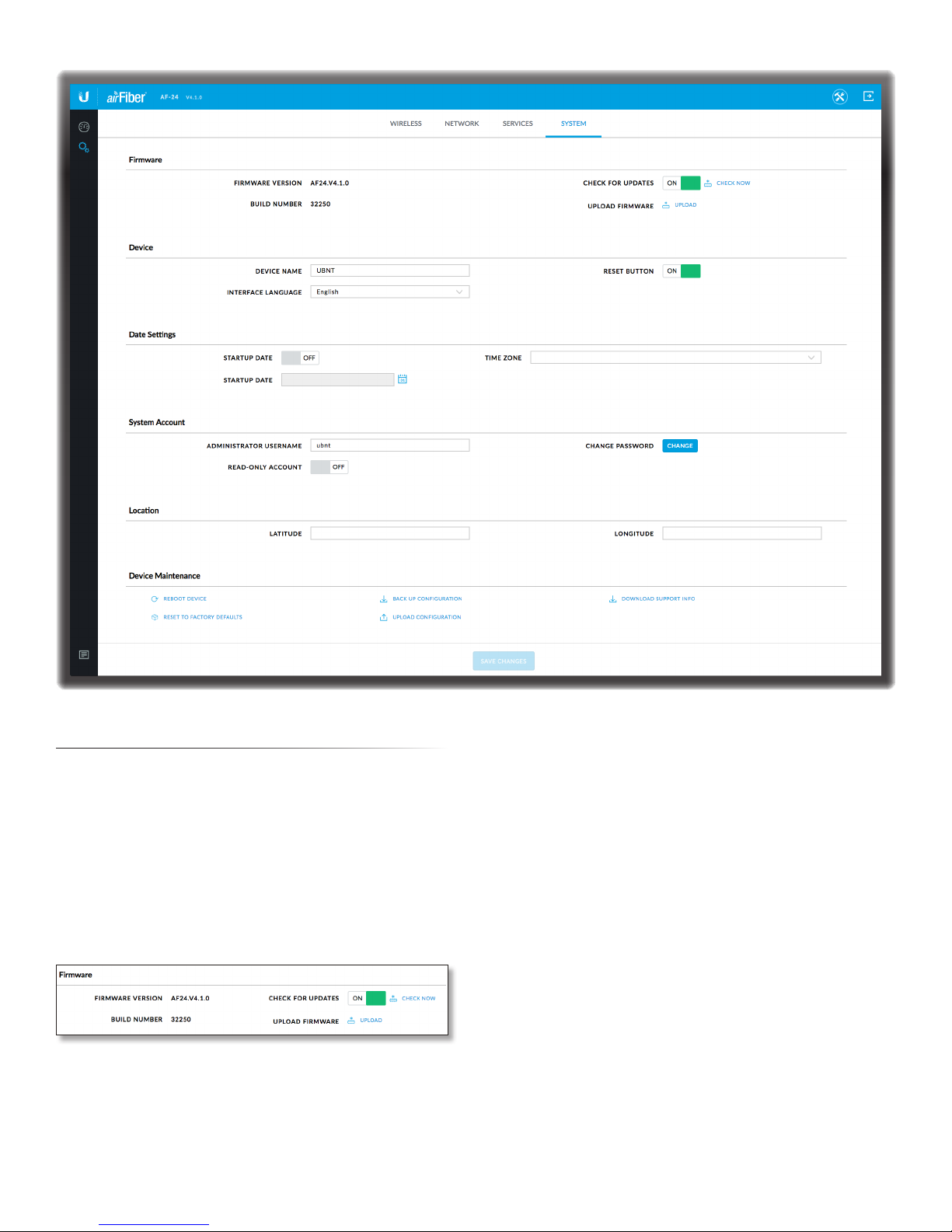
Chapter 8: System Tab airFiber AF-24/AF-24HD User Guide
Chapter 8: System Tab
The System tab contains administrative options. This page
enables the administrator to upload new firmware, edit
the device and date settings, configure the administrator
account, set the device’s location, reboot the airFiber
AF-24, reset it to factory default, back up or update the
configuration, and download support information.
Firmware Update
The controls in this section manage firmware
maintenance.
Firmware Version Displays the current firmware version.
Build Number Displays the build number of the firmware
version.
Check for Updates By default, the firmware automatically
checks for updates. To manually check for an update, click
Check Now.
Upload Firmware Click this button to update the airFiber
AF-24 with new firmware.
The airFiber AF-24 firmware update is compatible with
all configuration settings. The system configuration is
preserved while the AF-24 is updated with a new firmware
version. However, we recommend backing up your current
system configuration before updating the firmware.
This is a three-step procedure:
1. Click Choose File to locate the new firmware file. Select
the file and click Open.
2. Click Upload to upload the new firmware to the
airFiber AF-24.
3. The Uploaded Firmware Version is displayed. Click
Update to confirm.
Ubiquiti Networks, Inc.
41
Page 46
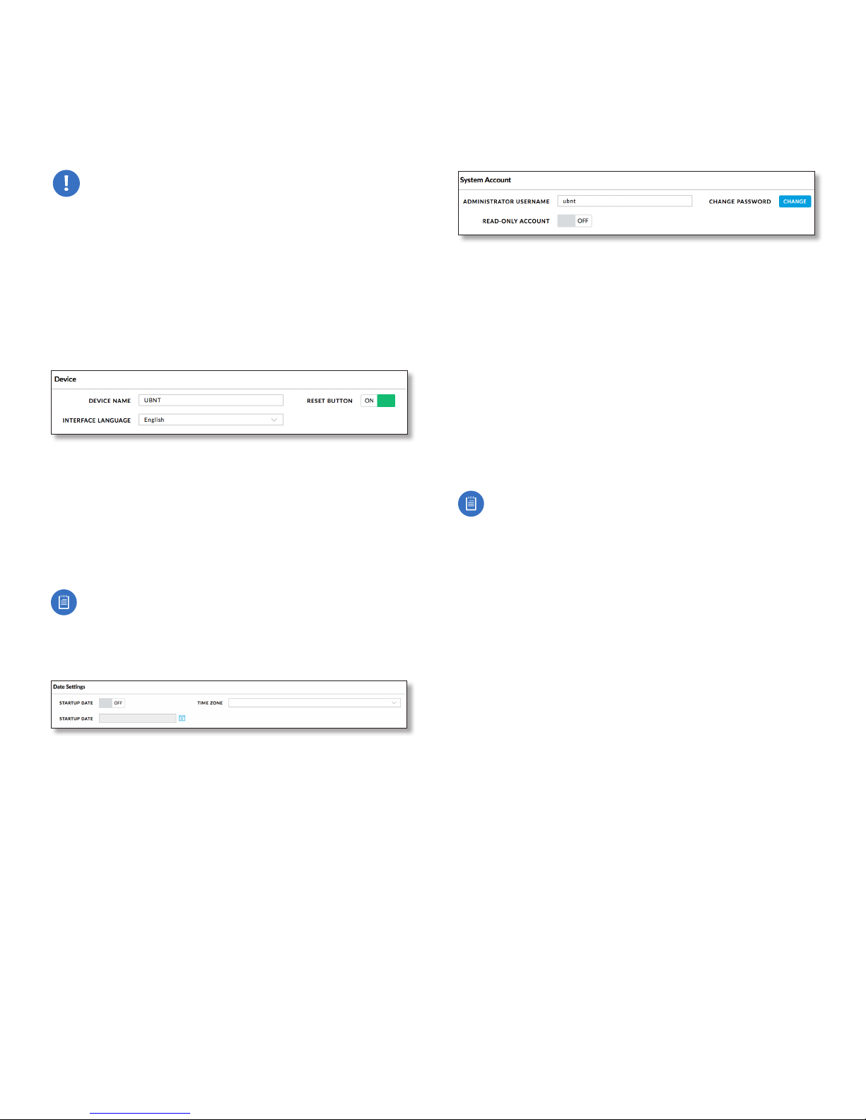
Chapter 8: System Tab airFiber AF-24/AF-24HD User Guide
If the firmware update is in process, you can close the
firmware update window, but this does not cancel the
firmware update. Please be patient, as the firmware
update routine can take three to seven minutes. You
cannot access the airFiber AF-24 until the firmware update
routine is completed.
WARNING: Do not power off, do not reboot, and do
not disconnect the airFiber AF-24 from the power
supply during the firmware update process as
these actions will damage the airFiber AF-24!
Device
The Device Name (host name) is the system-wide device
identifier. The SNMP agent reports it to authorized
management stations. The Device Name will be used in
popular router operating systems, registration screens,
and discovery tools.
Device Name Specifies the host name.
Interface Language Allows you to select the language
displayed in the web management interface. English is the
default language.
Reset Button To allow use of the airFiber AF-24’s physical
reset button, check the box. To prevent an accidental reset
to default settings, uncheck the box.
Note: You can reset the airFiber AF-24 to default
settings via the airFiber Configuration Interface. Go
to the System tab > Reset to Defaults.
Date Settings
Time Zone Specifies the time zone in relation to
Greenwich Mean Time (GMT).
Startup Date When enabled, you are able to change the
airFiber AF-24’s startup date.
• Startup Date Specifies the airFiber AF-24’s startup date.
Click the Calendar icon or manually enter the date in
the following format: 2-digit month/2-digit day/4-digit
year. For example, for April 5, 2012, enter 04/05/2012 in
the field.
System Accounts
You can change the administrator password to protect
your device from unauthorized changes. We recommend
that you change the default administrator password when
initially configuring the device.
Administrator Username Specifies the name of the
administrator. The maximum length is 31 characters.
Change Password Click Change to change the
administrator password. The maximum password length is
64 characters
• Current Password Enter the current password for
the administrator account. It is required to change the
Password or Administrator Username.
• New Password Enter the new password for the
administrator account.
• Verify New Password Re-enter the new password for
the administrator account.
Note: . If you upgrade to v4.0 or above from an
earlier version, use your old password (maximum
eight characters) for your first login. Then, change
the password as needed (maximum 32 characters).
To downgrade from v4.0 or above to an earlier
version, first ensure that the password is eight
characters or less in length; otherwise, login will
fail (to recover, reset the radio to factory defaults).
As you type the new password, the Password Strength
indicates the relative strength from orange (least secure)
to blue (most secure).
Read-Only Account Check the box to enable the
read-only account, which can only view the Dashboard.
Configure the username and password to protect your
device from unauthorized changes.
• Read-Only User Name Specifies the name of the
system user.
• Change Password Click Change to change the readonly account password.
- New Password Enter the new password for the
read-only account.
- Verify New Password Re-enter the new password for
the read-only account.
As you type the new password, the Password Strength
indicates the relative strength from orange (least secure)
to blue (most secure).
42
Ubiquiti Networks, Inc.
Page 47
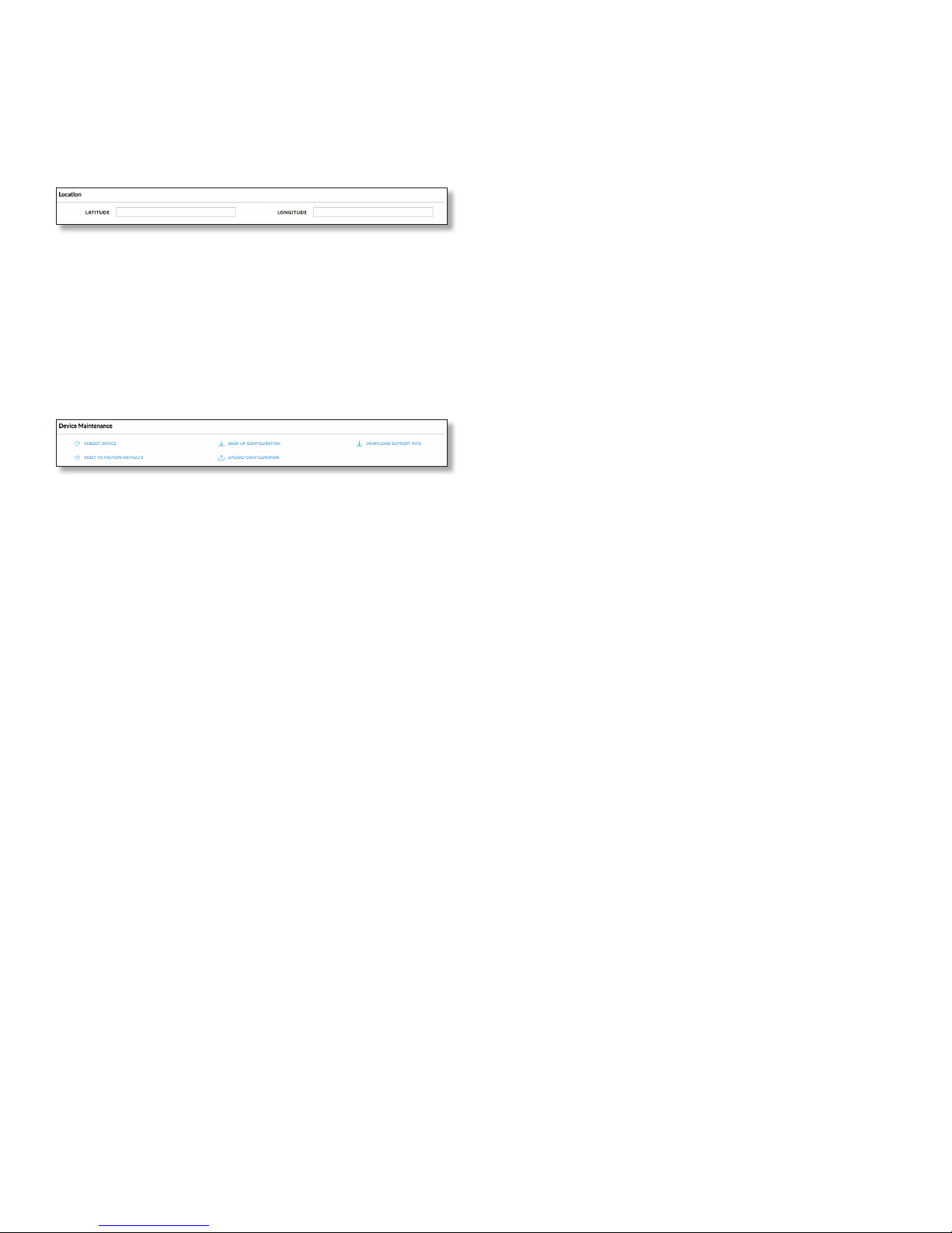
Location
After the on-board GPS determines the location of the
airFiber AF-24, its latitude and longitude are displayed.
If the GPS does not have a fix on its location, then
“Searching for Satellites” will be displayed.
Latitude The latitude of the airFiber AF-24’s location is
displayed.
Longitude The longitude of the airFiber AF-24’s location
is displayed.
Device Maintenance
The controls in this section manage the airFiber AF-24
maintenance routines.
Chapter 8: System Tab airFiber AF-24/AF-24HD User Guide
Reboot Device Initiates a full reboot cycle of the airFiber
AF-24. Reboot is the same as the hardware reboot, which
is similar to the power-off and power-on cycle. The system
configuration stays the same after the reboot cycle
completes. Any changes that have not been applied are
lost.
After the airFiber AF-24 reboots, the settings of the new
configuration are displayed in the Wireless, Network,
Advanced, Services, and System tabs of the airFiber
Configuration Interface.
Reset to Factory Defaults Click this option to reset the
airFiber AF-24 to the factory default settings. This option
will reboot the airFiber AF-24, and all factory default
settings will be restored. We recommend that you back
up your current system configuration before resetting the
airFiber AF-24 to its defaults.
Back Up Configuration Click this option to download the
current system configuration file.
The airFiber AF-24 configuration is stored in a plain text
file (.cfg file). You can back up, restore, or update the
system configuration file:
Upload Configuration Click this option to locate the
new configuration file. Select the file and click Open.
We recommend that you back up your current system
configuration before uploading the new configuration.
Download Support Info This generates a support
information file that the Ubiquiti support engineers can
use when providing customer support. This file only needs
to be generated at their request.
Ubiquiti Networks, Inc.
43
Page 48

Chapter 8: System Tab airFiber AF-24/AF-24HD User Guide
44
Ubiquiti Networks, Inc.
Page 49
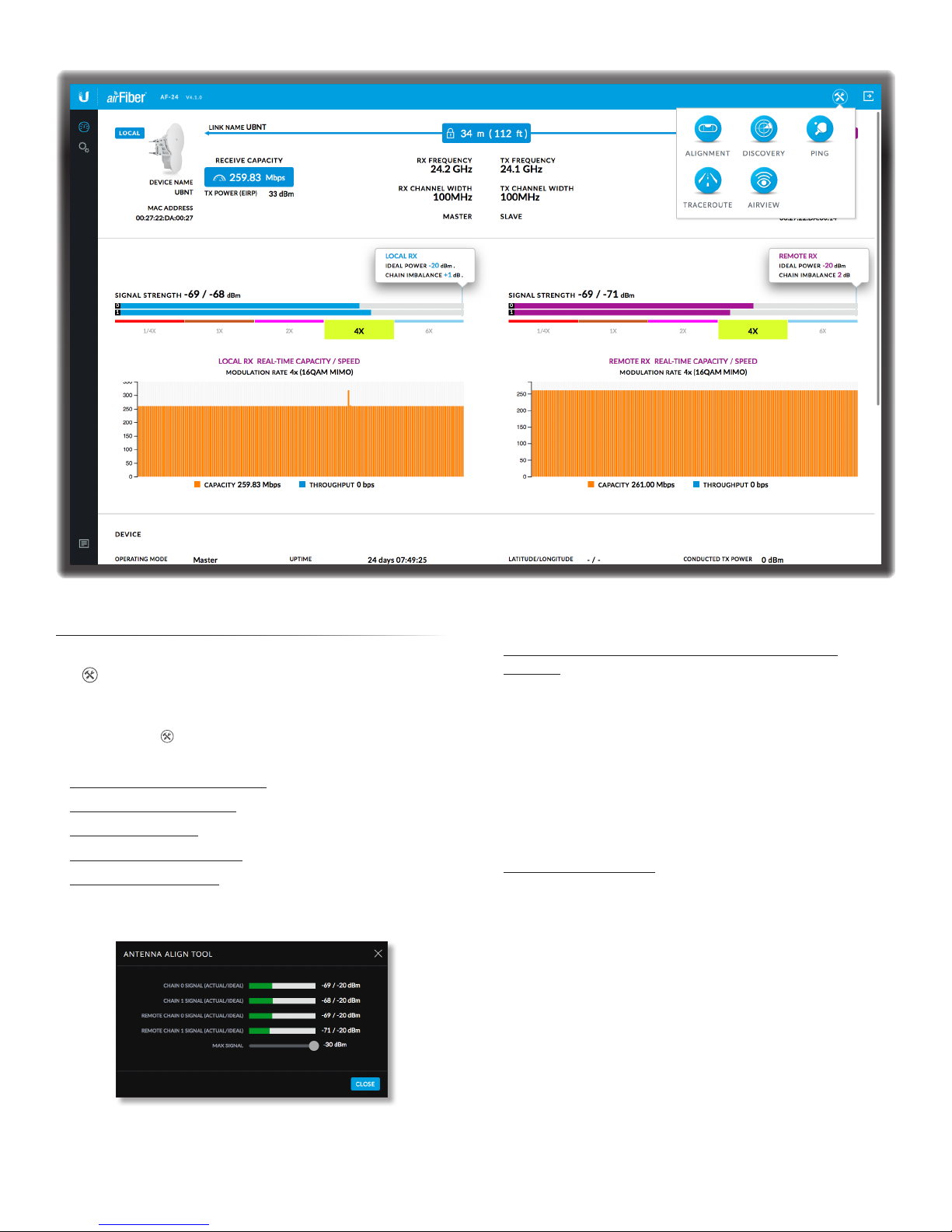
Chapter 9: ToolsairFiber AF-24/AF-24HD User Guide
Chapter 9: Tools
Each page of the airFiber Configuration Interface contains
the icon, which provides links to tools and information.
The icon is found near the upper-right corner of the
window.
When you click the following list of network
administration and monitoring tools is displayed:
• “Align Antenna” on page45
• “Discovery” on page46
• “Ping” on page46
• “Traceroute” on page46
• “airView” on page47
Align Antenna
Use the Align Antenna tool to point and optimize the
antenna in the direction of maximum link signal. (See
“Using the airFiber Configuration Interface” on
page15 for more details.) The Antenna Alignment
window reloads every 250 milliseconds.
Chain 0/1 Signal (Actual/Ideal) Displays the actual
power level (bar graph and first number) and ideal power
level (second number) in dBm of the received signal for
chain0 and chain1.
Changing the RX Gain on the Wireless tab does not affect
the Signal Strength values displayed on the Antenna
Alignment window. However, if “Overload” is displayed to
indicate overload condition, decrease the RX Gain. Refer to
“RX Gain” on page30 for more details about RX Gain
and overload condition.
Remote Chain 0/1 Signal (Actual/Ideal) Displays the
actual power level (bar graph and first number) and ideal
power level (second number) in dBm of the received
signal for chain0 and chain1 of the remote airFiber radio.
Max Signal Displays the maximum signal strength in
dBm. To adjust the range of the Max Signal meter, use the
slider control. If you reduce the range, the bar graphs will
be more sensitive to signal fluctuations, indicating the
offset of the maximum indicator value and the scale itself.
Ubiquiti Networks, Inc.
45
Page 50
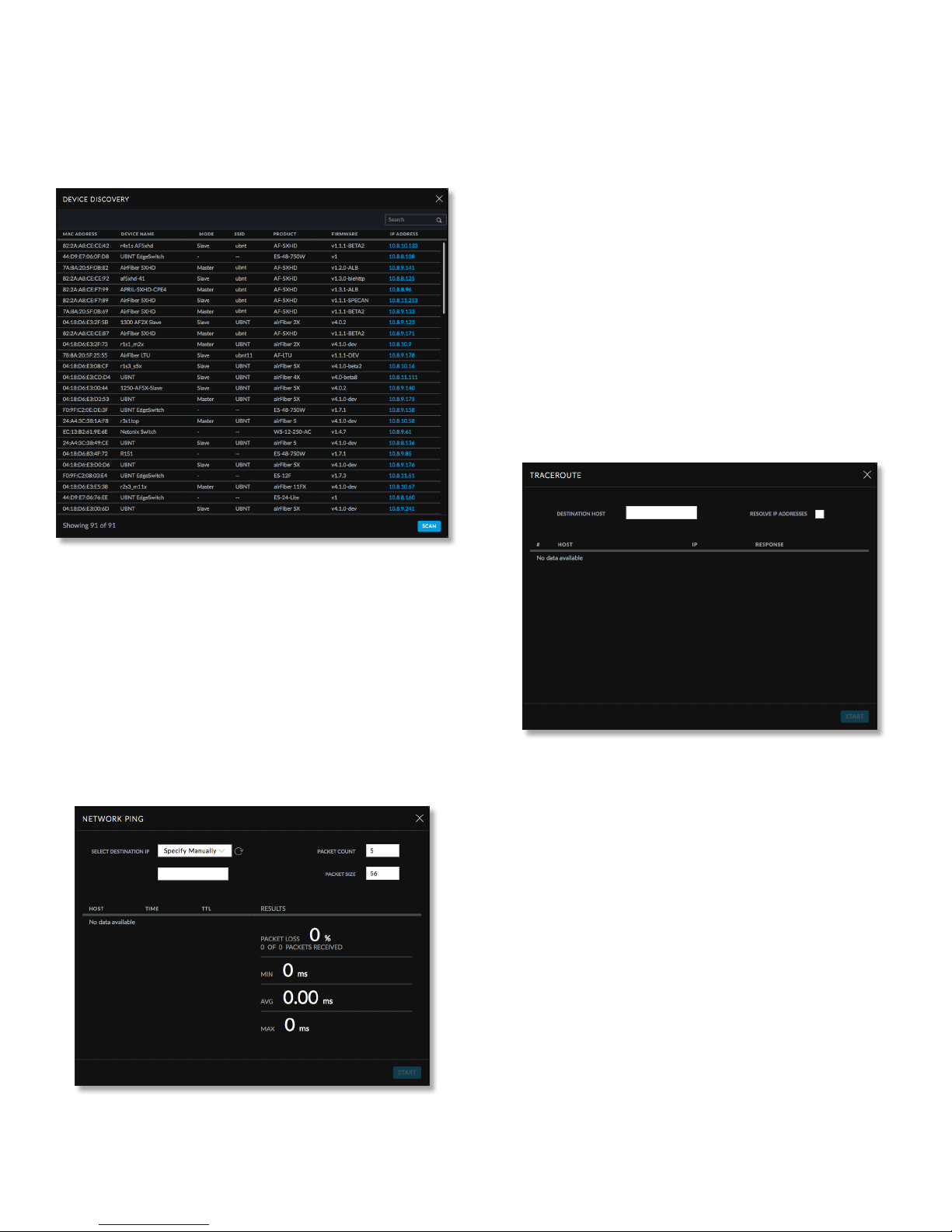
Chapter 9: Tools airFiber AF-24/AF-24HD User Guide
Discovery
The Device Discovery tool searches for all Ubiquiti devices
on your network. The Search field automatically filters
devices containing specified names or numbers as you
enter them.
Network Ping
Select Destination IP You have two options:
• Select a remote system IP from the drop-down list,
which is generated automatically.
• Select specify manually and enter the IP address in the
field displayed below.
Packet Count Enter the number of packets to send for
the ping test.
Packet Size Specify the size of the packet.
Start Click this button to start the test.
Packet loss statistics and latency time evaluation are
displayed after the test is completed.
Traceroute
The Traceroute tool traces the hops from the airFiber AF-24
to a specified outgoing IP address. Use this tool to find the
route taken by ICMP packets across the network to the
destination host.
It reports the MAC Address (except for airFiber devices),
Device Name, Mode, SSID, Product type, Firmware version,
and IP Address for each Ubiquiti device. To access a device
configuration through its web management interface,
click the device’s IP address.
To refresh the window, click Scan.
Ping
You can ping other devices on the network directly from
the airFiber AF-24. The Ping tool uses ICMP packets to
check the preliminary link quality and packet latency
estimation between two network devices.
Destination Host Enter the IP address of the destination
host.
Resolve IP Addresses Select this option to resolve the IP
addresses symbolically rather than numerically.
Start Click this button to start the test.
Responses are displayed after the test is completed.
46
Ubiquiti Networks, Inc.
Page 51
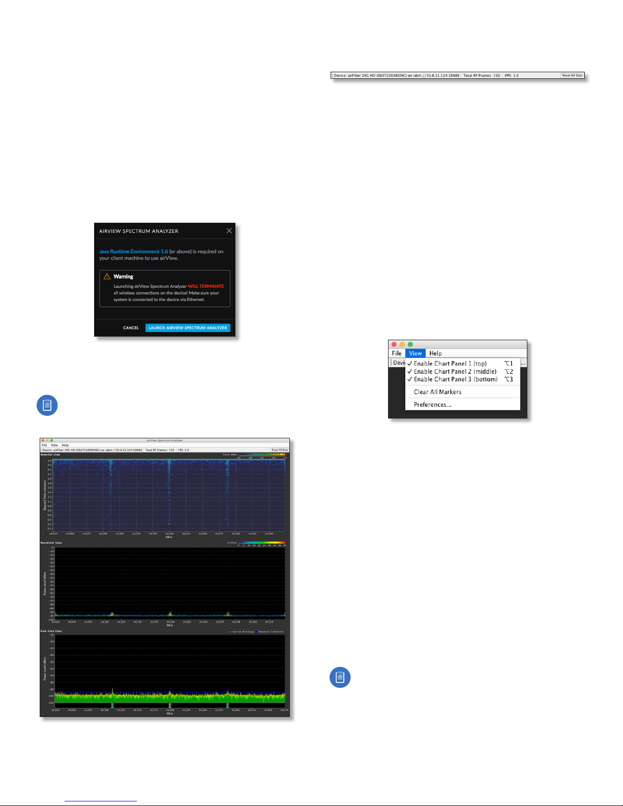
Chapter 9: ToolsairFiber AF-24/AF-24HD User Guide
airView
Use the airView Spectrum Analyzer to analyze the noise
environment of the radio spectrum and intelligently select
the optimal frequency to install a PtP airFiber AF-24 link.
There are two system requirements for the airView
Spectrum Analyzer:
• Your system is connected to the device via Ethernet.
Launching airView will terminate all wireless
connections on the device.
• Java Runtime Environment 1.6 (or above) is required on
your client machine to use airView.
On first use, the following window appears.
Main View
Device Displays the device name, MAC (Media Access
Control) address, and IP address of the device running
airView.
Total RF Frames Displays the total number of Radio
Frequency (RF) frames gathered since the start of the
airView session or since the Reset All Data button was last
clicked.
FPS Displays the total number of frames per second (FPS)
gathered since the start of the airView session or since
the Reset All Data button was last clicked. The wider the
interval amplitude, the fewer the FPS will be gathered.
Reset All Data Click to reset all gathered data. Use this
option to analyze the spectrum for another location or
address.
File Menu
Click Exit to end the airView session.
View Menu
• Launch airView Click Launch airView to download the
Java Network Launch Protocol (jnlp) file and complete
the launch of airView.
Note: Depending on your browser settings, you
may also see addtional prompts; continue through
these as needed to finish launching airView.
Enable Chart Panel 1 (top) Displays the Waterfall or
Channel Usage chart in Chart Panel 1, depending on
which option you have selected in Preferences. This
time-based graph shows the aggregate energy collected
or channel usage for each frequency since the start of the
airView session.
Enable Chart Panel 2 (middle) Displays the Waveform
chart in Chart Panel 2. This time-based graph shows the RF
signature of the noise environment since the start of the
airView session. The energy color designates its amplitude.
Cooler colors represent lower energy levels (with blue
representing the lowest levels) in that frequency bin, and
warmer colors (yellow, orange, or red) represent higher
energy levels in that frequency bin.
Enable Chart Panel 3 (bottom) Displays the Real-time
chart (traditional spectrum analyzer) in Chart Panel 3.
Energy (in dBm) is shown in real time as a function of
frequency.
Ubiquiti Networks, Inc.
Note: Energy is defined as the power ratio in
decibels (dB) of the measured power referenced to
one milliwatt (mW).
47
Page 52
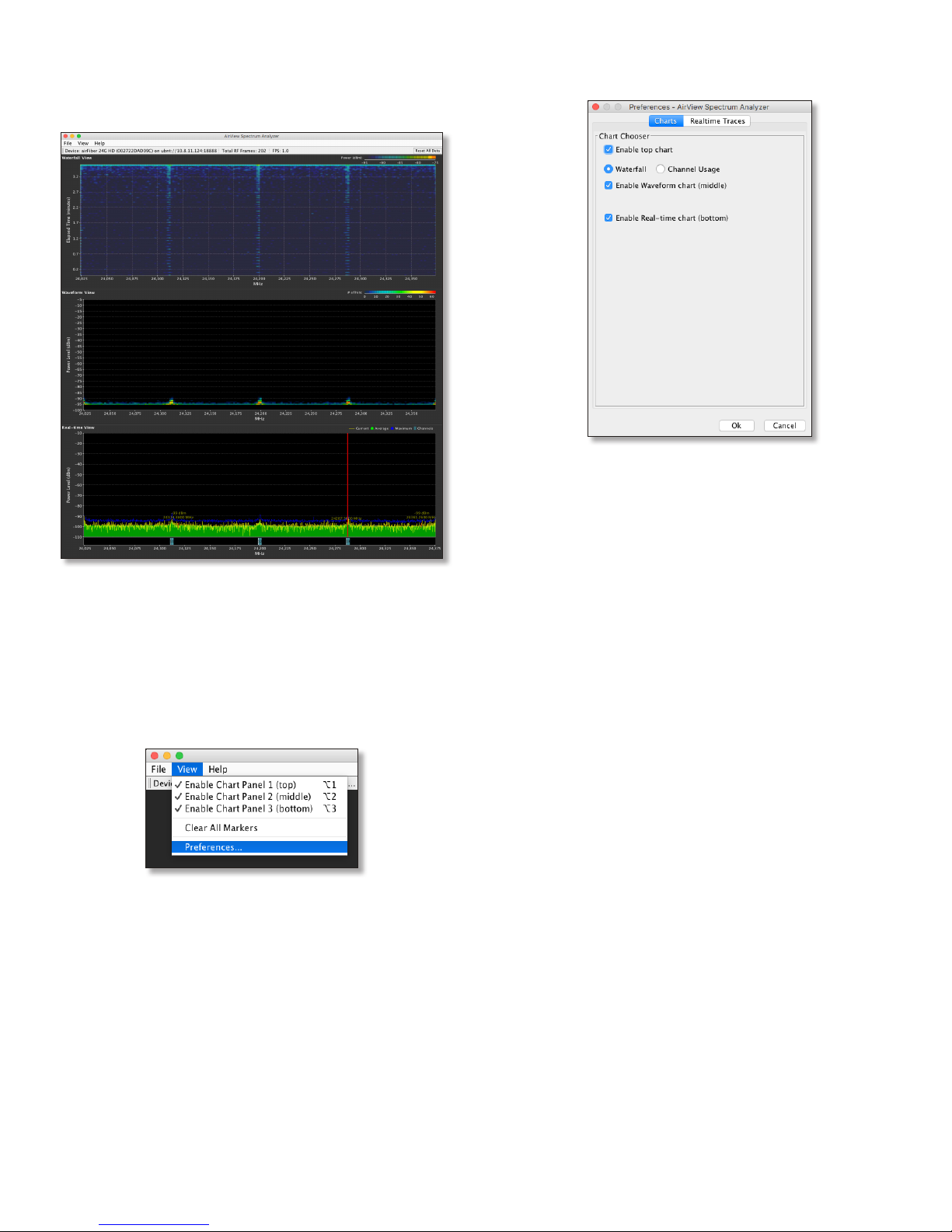
Chapter 9: Tools airFiber AF-24/AF-24HD User Guide
Clear All Markers Resets all previously assigned
markers. Markers are assigned by clicking a point, which
corresponds with a frequency on the Real-time chart.
airView Window with Marker
Preferences Changes airView settings, such as enabling
or disabling charts and traces, or specifying the frequency
interval.
Preferences
Select View > Preferences to display the Preferences airView Spectrum Analyzer window.
The Preferences - airView Spectrum Analyzer window
provides options on two tabs: Charts and Realtime Traces.
Charts
Enable top chart Check the box to enable the top chart.
Select the desired chart to display in the top chart panel
on the main view. There are two options:
• Waterfall
energy collected for each frequency since the start
of the airView session. The energy color designates
its amplitude. Cooler colors represent lower energy
levels (with blue representing the lowest levels) in that
frequency bin, and warmer colors (yellow, orange, or red)
represent higher energy levels in that frequency bin.
The Waterfall View’s legend (top-right corner) provides
a numerical guide associating the various colors to
power levels (in dBm). The low end of that legend (left)
is always adjusted to the calculated noise floor, and the
high end (right) is set to the highest detected power
level since the start of the airView session.
• Channel Usage Displays each Wi-Fi channel’s relative
“crowdedness” as a percentage. The airView Spectrum
Analyzer calculates this percentage by analyzing both
the popularity and strength of RF energy in that channel
since the start of the airView session.
Enable Waveform chart (middle) Check the box to
enable the middle chart. This time-based graph shows
the RF signature of the noise environment since the
start of the airView session. The energy color designates
its amplitude. Cooler colors represent lower energy
levels (with blue representing the lowest levels) in that
frequency bin, and warmer colors (yellow, orange, or red)
represent higher energy levels in that frequency bin.
The spectral view over time will display the steady-state RF
energy signature of a given environment.
Enable Real-time chart (bottom) Check the box to
enable the bottom chart. This graph displays a traditional
spectrum analyzer in which energy (in dBm) is shown in
real time as a function of frequency. There are three traces
in this view:
This time-based graph shows the aggregate
48
Ubiquiti Networks, Inc.
Page 53
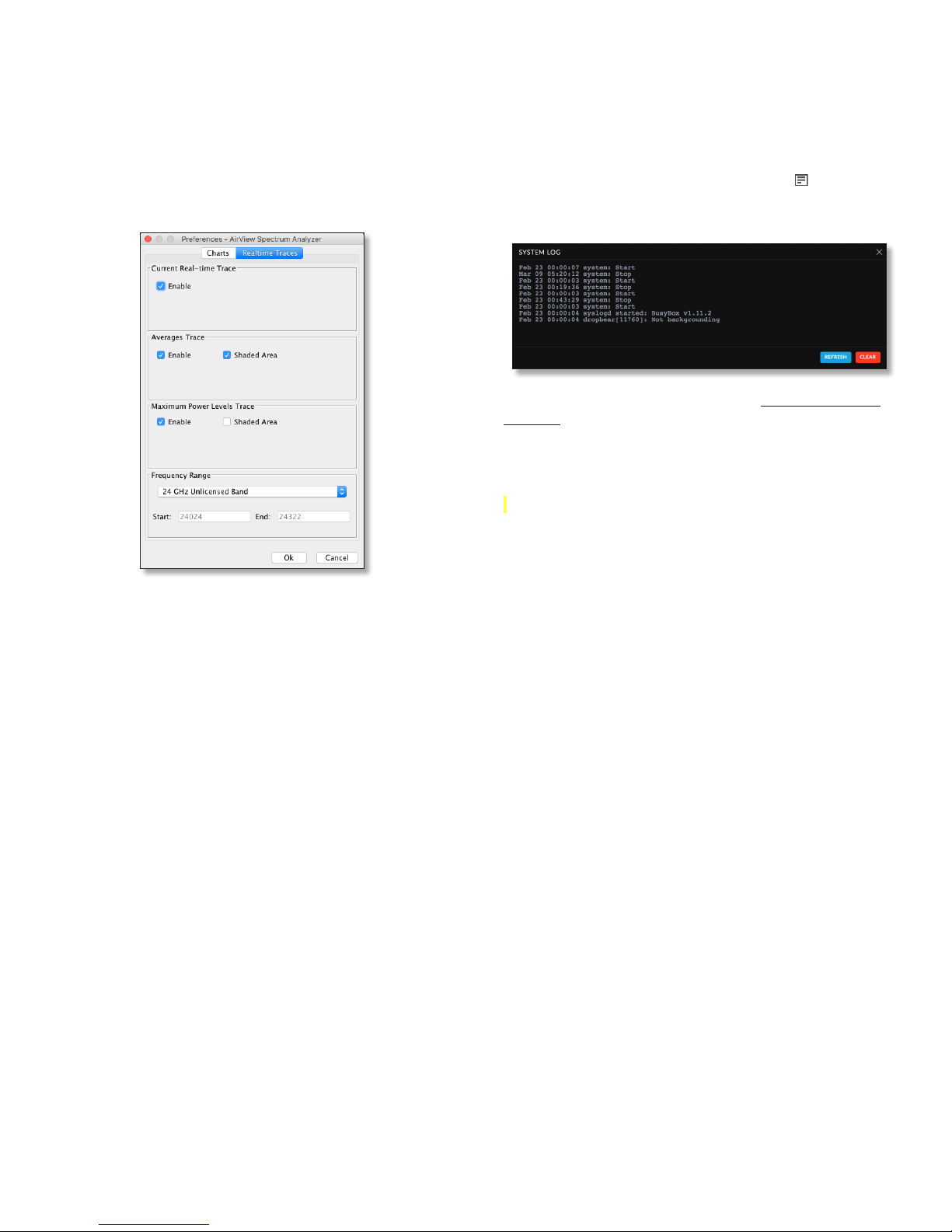
Chapter 9: ToolsairFiber AF-24/AF-24HD User Guide
• Current (Yellow) Shows the real-time energy seen by
the device as a function of frequency.
• Average (Green) Shows the running average energy
across frequency.
• Maximum (Blue) Shows updates and maximum power
levels across frequency.
Realtime Traces
Help
Click About to view the version and build number of the
airView Spectrum Analyzer.
Log
When logging is enabled, click the Log icon at the
bottom left corner of the page to open the System Log
window, which provides a record of events on the system.
By default, logging is not enabled; see “System Log” on
page39 for information on how to enable logging.
Click Refresh to update the display with the most recent
information. To clear the system log, click Clear, and then
click Yes to verify.
The following settings apply only to the Real-time chart:
Current Real-time Trace Check the Enable box to enable
the real-time trace. When enabled, the yellow outline on
the Real-time chart represents the real-time power level of
each frequency. The refresh speed depends on the FPS.
Averages Trace Check the Enable box to enable the
averages trace. When enabled, the averages trace is
represented by the green area on the Real-time chart,
which displays the average received power level data
since the start of the airView session. To enable a shaded
green area, check the Shaded Area box. To display only
a green outline without the shaded area, uncheck the
Shaded Area box.
Maximum Power Levels Trace Check the Enable box to
enable the maximum power trace. When enabled, the
maximum power trace is represented by the blue area on
the Real-time chart, which displays the maximum received
power level data since the start of the airView session. To
enable a shaded blue area, check the Shaded Area box.
To display only a blue outline without the shaded area,
uncheck the Shaded Area box.
Frequency Range Select the amplitude of the
frequency interval to be scanned from the Frequency
Range drop-down list. Available frequencies are device-
dependent. There are pre-defined ranges for the most
popular bands. You can enter a custom range; select
Custom Range from the Frequency Range drop-down list
and enter the desired values in the Start and End fields.
Ubiquiti Networks, Inc.
49
Page 54

Chapter 9: Tools airFiber AF-24/AF-24HD User Guide
50
Ubiquiti Networks, Inc.
Page 55
Appendix A: SpecificationsairFiber AF-24/AF-24HD User Guide
Appendix A: Specifications
airFiber AF-24
Dimensions 649 x 426 x 303 mm (25.55 x 16.77 x 11.93 in)
Weight 10.5 kg (23.15 lb)
(Mount Included)
Operating Frequency 24.05 – 24.25 GHz
Max. Power Consumption < 50W
Power Supply 50V, 1.2A PoE GigE Adapter (Included)
Power Method Passive Power over Ethernet (42-58VDC)
Certications CE, FCC, IC
Wind Loading 480 N @ 200 km/hr (108 lbf @ 125 mph)
Wind Survivability 200 km/hr (125 mph)
Mounting Pole Mount Kit (Included)
Operating Temperature -40 to 55°C (-40 to 131° F)
LEDs (8) Status LEDs:
Data Port Speed
Data Port Link/Activity
Conguration Port Speed
Conguration Port Link/Activity
GPS Synchronization
Modulation Mode
Master/Slave
RF Status
(1) Two-Digit LED Display Calibrated in dBm
Button Reset
Interface
Data Port (1) 10/100/1000 Ethernet Port
Conguration Port (1) 10/100 Ethernet Port
Auxiliary Port (1) RJ-12, Alignment Tone Port
System
Maximum Throughput 1.4+ Gbps
Maximum Range 13+ km (8+ mi)
Packets per Second > 1 Million
Encryption 128-Bit AES
Forward Error Correction 164/205
Cyclic Prex 1/16 Fixed
Uplink/Downlink Ratio 50% Fixed
Modulation Sensitivity FDD Capacity* TDD Capacity*
64QAM -66 dBm 1500 Mbps 760 Mbps
16QAM -72 dBm 1000 Mbps 507 Mbps
QPSK MIMO -78 dBm 500 Mbps 253 Mbps
QPSK SISO -80 dBm 250 Mbps 127 Mbps
¼x QPSK SISO -87 dBm 62.5 Mbps 31.7 Mbps
Ubiquiti Networks, Inc.
AF-24 Receive Sensitivity
* FDD = (2) 100 MHz channels and TDD = (1) 100 MHz channel
51
Page 56
Appendix A: Specifications airFiber AF-24/AF-24HD User Guide
AF-24 Radio Frequency
GPS GPS Clock Synchronization
Transceiver
EIRP ~33 dBm (FCC/IC), ~20 dBm (CE), ~40 dBm (Other Regions)
Frequency Accuracy ±2.5 ppm without GPS Synchronization
± 0.2 ppm with GPS Synchronization
Channel Bandwidth 100 MHz
Operating Channels 24.1 GHz, 24.2 GHz
Modulation 64QAM MIMO
16QAM MIMO
QPSK MIMO
QPSK SISO
¼x QPSK SISO
Integrated Split Antenna
TX Gain 33 dBi
RX Gain 38 dBi
Beamwidth < 3.5°
Front-to-Back Ratio 70 dB
Polarity Dual-Slant Polarization
Cross-Polarity Isolation > 28 dB
AF-24 Capacity (Mbps)
Rate Modulation 100 MHz Channel Width*
6x 64QAM MIMO 1500.0
4x 16QAM MIMO 1000.0
2x QPSK MIMO 500.0
1x QPSK SISO 250.0
¼x ¼ QPSK SISO 62.5
* Aggregate capacity in Full-Duplex mode
52
Ubiquiti Networks, Inc.
Page 57
Appendix A: SpecificationsairFiber AF-24/AF-24HD User Guide
airFiber AF-24HD
Dimensions 593 x 768 x 370 mm (23.35 x 30.24 x 14.57 in)
Weight 17.3 kg (38.14 lb)
(Mount Included)
Operating Frequency 24.05 – 24.25 GHz
Max. Power Consumption < 50W
Power Supply 50V, 1.2A PoE GigE Adapter (Included)
Power Method Passive Power over Ethernet (42-58VDC)
Certications CE, FCC, IC
Wind Loading 770 N @ 200 km/hr (170 lbf @ 125 mph)
Wind Survivability 200 km/hr (125 mph)
Mounting Pole Mount Kit (Included)
Operating Temperature -40 to 55°C (-40 to 131° F)
LEDs (8) Status LEDs:
Data Port Speed
Data Port Link/Activity
Conguration Port Speed
Conguration Port Link/Activity
GPS Synchronization
Modulation Mode
Master/Slave
RF Status
(1) Two-Digit LED Display Calibrated in dBm
Button Reset
Interface
Data Port (1) 10/100/1000 Ethernet Port
Conguration Port (1) 10/100 Ethernet Port
Auxiliary Port (1) RJ-12, Alignment Tone Port
System
Maximum Throughput 1.4+ Gbps
Maximum Range 13+ km (8+ mi)
Packets per Second > 1 Million
Encryption 128-Bit AES
Uplink/Downlink Ratio 50% Fixed
Modulation Sensitivity FDD Capacity* TDD Capacity*
256QAM -60 dBm 2000 Mbps 1024 Mbps
64QAM -66 dBm 1500 Mbps 760 Mbps
16QAM -72 dBm 1000 Mbps 507 Mbps
QPSK MIMO -78 dBm 500 Mbps 253 Mbps
QPSK SISO -80 dBm 250 Mbps 127 Mbps
¼x QPSK SISO -87 dBm 62.5 Mbps 31.7 Mbps
Ubiquiti Networks, Inc.
AF-24HD Receive Sensitivity
* FDD = (2) 100 MHz channels and TDD = (1) 100 MHz channel
53
Page 58
Appendix A: Specifications airFiber AF-24/AF-24HD User Guide
AF-24HD Radio Frequency
GPS GPS Clock Synchronization
Transceiver
EIRP ~33 dBm (FCC/IC), ~20 dBm (CE), ~40 dBm (Other Regions)
Frequency Accuracy ±2.5 ppm without GPS Synchronization
± 0.2 ppm with GPS Synchronization
Channel Bandwidth 100 MHz
Operating Channels 24.1 GHz, 24.2 GHz
Modulation 256QAM MIMO
64QAM MIMO
16QAM MIMO
QPSK MIMO
QPSK SISO
¼x QPSK SISO
Integrated Split Antenna
TX Gain 33 dBi
RX Gain 40 dBi
Beamwidth < 3.5°
Front-to-Back Ratio 70 dB
Polarity Dual-Slant Polarization
Cross-Polarity Isolation > 28 dB
AF-24HD Capacity (Mbps)
Rate Modulation 100 MHz Channel Width*
8x 256QAM MIMO 2000.0
6x 64QAM MIMO 1500.0
4x 16QAM MIMO 1000.0
2x QPSK MIMO 500.0
1x QPSK SISO 250.0
¼x ¼ QPSK SISO 62.5
* Aggregate capacity in Full-Duplex mode
54
Ubiquiti Networks, Inc.
Page 59

Appendix B: Safety Notices
1. Read, follow, and keep these instructions.
2. Heed all warnings.
3. Only use attachments/accessories specified by the
manufacturer.
WARNING: Do not use this product in location that can be
submerged by water.
WARNING: Avoid using this product during an electrical
storm. There may be a remote risk of electric shock from
lightning.
Electrical Safety Information
1. Compliance is required with respect to voltage,
frequency, and current requirements indicated on the
manufacturer’s label. Connection to a different power
source than those specified may result in improper
operation, damage to the equipment or pose a fire
hazard if the limitations are not followed.
2. There are no operator serviceable parts inside this
equipment. Service should be provided only by a
qualified service technician.
3. This equipment is provided with a detachable power
cord which has an integral safety ground wire intended
for connection to a grounded safety outlet.
a. Do not substitute the power cord with one that
is not the provided approved type. Never use an
adapter plug to connect to a 2-wire outlet as this
will defeat the continuity of the grounding wire.
b. The equipment requires the use of the ground wire
as a part of the safety certification, modification or
misuse can provide a shock hazard that can result in
serious injury or death.
c. Contact a qualified electrician or the manufacturer
if there are questions about the installation prior to
connecting the equipment.
d. Protective earthing is provided by Listed AC
adapter. Building installation shall provide
appropriate short-circuit backup protection.
e. Protective bonding must be installed in accordance
with local national wiring rules and regulations.
Appendix B: Safety NoticesairFiber AF-24/AF-24HD User Guide
Ubiquiti Networks, Inc.
55
Page 60

Appendix B: Safety Notices airFiber AF-24/AF-24HD User Guide
56
Ubiquiti Networks, Inc.
Page 61

Appendix C: WarrantyairFiber AF-24/AF-24HD User Guide
Appendix C: Warranty
Limited Warranty
UBIQUITI NETWORKS, Inc (“UBIQUITI NETWORKS”)
warrants that the product(s) furnished hereunder (the
“Product(s)”) shall be free from defects in material and
workmanship for a period of one (1) year from the date
of shipment by UBIQUITI NETWORKS under normal use
and operation. UBIQUITI NETWORKS’ sole and exclusive
obligation and liability under the foregoing warranty
shall be for UBIQUITI NETWORKS, at its discretion, to
repair or replace any Product that fails to conform to the
above warranty during the above warranty period. The
expense of removal and reinstallation of any Product is
not included in this warranty. The warranty period of any
repaired or replaced Product shall not extend beyond its
original term.
Warranty Conditions
The above warranty does not apply if the Product:
(I) has been modified and/or altered, or an addition
made thereto, except by Ubiquiti Networks, or
Ubiquiti Networks’ authorized representatives, or as
approved by Ubiquiti Networks in writing;
(II) has been painted, rebranded or physically modified in
any way;
(III) has been damaged due to errors or defects in cabling;
(IV) has been subjected to misuse, abuse, negligence,
abnormal physical, electromagnetic or electrical
stress, including lightning strikes, or accident;
(V) has been damaged or impaired as a result of using
third party firmware; or
(VI) has no original Ubiquiti MAC label, or is missing any
other original Ubiquiti label(s).
(VII) has not been received by Ubiquiti within 30 days of
issuance of the RMA.
In addition, the above warranty shall apply only if: the
product has been properly installed and used at all times
in accordance, and in all material respects, with the
applicable Product documentation; all Ethernet cabling
runs use CAT5 (or above), and for outdoor installations,
shielded Ethernet cabling is used, and for indoor
installations, indoor cabling requirements are followed.
Returns
No Products will be accepted for replacement or repair
without obtaining a Return Materials Authorization (RMA)
number from UBIQUITI NETWORKS during the warranty
period, and the Products being received at UBIQUITI
NETWORKS’ facility freight prepaid in accordance with the
RMA process of UBIQUITI NETWORKS. Products returned
without an RMA number will not be processed and will be
returned freight collect or subject to disposal. Information
on the RMA process and obtaining an RMA number can be
found at: www.ubnt.com/support/warranty
Disclaimer
EXCEPT FOR ANY EXPRESS WARRANTIES PROVIDED
HEREIN, UBIQUITI NETWORKS, ITS AFFILIATES, AND ITS
AND THEIR THIRD PARTY DATA, SERVICE, SOFTWARE AND
HARDWARE PROVIDERS HEREBY DISCLAIM AND MAKE
NO OTHER REPRESENTATION OR WARRANTY OF ANY
KIND, EXPRESS, IMPLIED OR STATUTORY, INCLUDING,
BUT NOT LIMITED TO, REPRESENTATIONS, GUARANTEES,
OR WARRANTIES OF MERCHANTABILITY, ACCURACY,
QUALITY OF SERVICE OR RESULTS, AVAILABILITY,
SATISFACTORY QUALITY, LACK OF VIRUSES, QUIET
ENJOYMENT, FITNESS FOR A PARTICULAR PURPOSE AND
NON-INFRINGEMENT AND ANY WARRANTIES ARISING
FROM ANY COURSE OF DEALING, USAGE OR TRADE
PRACTICE IN CONNECTION WITH SUCH PRODUCTS
AND SERVICES. BUYER ACKNOWLEDGES THAT NEITHER
UBIQUITI NETWORKS NOR ITS THIRD PARTY PROVIDERS
CONTROL BUYER’S EQUIPMENT OR THE TRANSFER OF
DATA OVER COMMUNICATIONS FACILITIES, INCLUDING
THE INTERNET, AND THAT THE PRODUCTS AND SERVICES
MAY BE SUBJECT TO LIMITATIONS, INTERRUPTIONS,
DELAYS, CANCELLATIONS AND OTHER PROBLEMS
INHERENT IN THE USE OF COMMUNICATIONS FACILITIES.
UBIQUITI NETWORKS, ITS AFFILIATES AND ITS AND THEIR
THIRD PARTY PROVIDERS ARE NOT RESPONSIBLE FOR ANY
INTERRUPTIONS, DELAYS, CANCELLATIONS, DELIVERY
FAILURES, DATA LOSS, CONTENT CORRUPTION, PACKET
LOSS, OR OTHER DAMAGE RESULTING FROM ANY OF THE
FOREGOING. In addition, UBIQUITI NETWORKS does not
warrant that the operation of the Products will be errorfree or that operation will be uninterrupted. In no event
shall UBIQUITI NETWORKS be responsible for damages
or claims of any nature or description relating to system
performance, including coverage, buyer’s selection of
products (including the Products) for buyer’s application
and/or failure of products (including the Products) to meet
government or regulatory requirements.
WARNING: Failure to properly ground your
airFiber units will void your warranty. (Please
follow the instructions on “Grounding” on page
10 for installation of the ground wires.)
Limitation of Liability
EXCEPT TO THE EXTENT PROHIBITED BY LOCAL LAW, IN NO
EVENT WILL UBIQUITI OR ITS SUBSIDIARIES, AFFILIATES OR
SUPPLIERS BE LIABLE FOR DIRECT, SPECIAL, INCIDENTAL,
CONSEQUENTIAL OR OTHER DAMAGES (INCLUDING LOST
PROFIT, LOST DATA, OR DOWNTIME COSTS), ARISING
OUT OF THE USE, INABILITY TO USE, OR THE RESULTS OF
USE OF THE PRODUCT, WHETHER BASED IN WARRANTY,
CONTRACT, TORT OR OTHER LEGAL THEORY, AND
WHETHER OR NOT ADVISED OF THE POSSIBILITY OF SUCH
DAMAGES.
Ubiquiti Networks, Inc.
57
Page 62

Appendix C: Warranty airFiber AF-24/AF-24HD User Guide
Note
Some countries, states and provinces do not allow
exclusions of implied warranties or conditions, so the
above exclusion may not apply to you. You may have
other rights that vary from country to country, state to
state, or province to province. Some countries, states
and provinces do not allow the exclusion or limitation of
liability for incidental or consequential damages, so the
above limitation may not apply to you. EXCEPT TO THE
EXTENT ALLOWED BY LOCAL LAW, THESE WARRANTY
TERMS DO NOT EXCLUDE, RESTRICT OR MODIFY, AND
ARE IN ADDITION TO, THE MANDATORY STATUTORY
RIGHTS APPLICABLE TO THE LICENSE OF ANY SOFTWARE
(EMBEDDED IN THE PRODUCT) TO YOU. The United
Nations Convention on Contracts for the International Sale
of Goods shall not apply to any transactions regarding the
sale of the Products.
58
Ubiquiti Networks, Inc.
Page 63
Appendix D: Compliance InformationairFiber AF-24/AF-24HD User Guide
Appendix D: Compliance
Information
Installer Compliance Responsibility
Devices must be professionally installed and it is the
professional installer’s responsibility to make sure the
device is operated within local country regulatory
requirements.
FCC
Changes or modifications not expressly approved by the
party responsible for compliance could void the user’s
authority to operate the equipment.
This device complies with Part 15 of the FCC Rules.
Operation is subject to the following two conditions:
1. This device may not cause harmful interference, and
2. This device must accept any interference received,
including interference that may cause undesired
operation.
This equipment has been tested and found to comply
with the limits for a Class A digital device, pursuant to part
15 of the FCC Rules. These limits are designed to provide
reasonable protection against harmful interference
when the equipment is operated in a commercial
environment. This equipment generates, uses, and can
radiate radio frequency energy and, if not installed and
used in accordance with the instruction manual, may
cause harmful interference to radio communications.
Operations of this equipment in a residential area is likely
to cause harmful interference in which case the user will
be required to correct the interference at his own expense.
RF Exposure Warning
The antennas used for this transmitter must be installed
to provide a separation distance of at least 107 cm from
all persons and must not be located or operating in
conjunction with any other antenna or transmitter.
Les antennes utilisées pour ce transmetteur doivent être
installé en considérant une distance de séparation de
toute personnes d’au moins 107 cm et ne doivent pas être
localisé ou utilisé en conflit avec tout autre antenne ou
transmetteur.
CE Marking
CE marking on this product represents the product is in
compliance with all directives that are applicable to it.
This equipment is intended to be accessed only by service
personnel and/or trained professionals.
ISED Canada
CAN ICES-3(A)/NMB-3(A)
This device complies with ISED Canada licence-exempt
RSS standard(s). Operation is subject to the following two
conditions:
1. This device may not cause interference, and
2. This device must accept any interference, including
interference that may cause undesired operation of the
device.
CAN ICES-3(A)/NMB-3(A)
Le présent appareil est conforme aux CNR d’ISDE Canada
applicables aux appareils radio exempts de licence.
L’exploitation est autorisée aux deux conditions suivantes:
1. l’appareil ne doit pas produire de brouillage;
2. l’appareil doit accepter tout brouillage radioélectrique
subi, même si le brouillage est susceptible d’en
compromettre le fonctionnement.
Ubiquiti Networks, Inc.
59
Page 64

Appendix D: Compliance Information airFiber AF-24/AF-24HD User Guide
RoHS/WEEE Compliance Statement
English
European Directive 2012/19/EU requires that the
equipment bearing this symbol on the product and/
or its packaging must not be disposed of with unsorted
municipal waste. The symbol indicates that this product
should be disposed of separately from regular household
waste streams. It is your responsibility to dispose
of this and other electric and electronic equipment
via designated collection facilities appointed by the
government or local authorities. Correct disposal
and recycling will help prevent potential negative
consequences to the environment and human health. For
more detailed information about the disposal of your old
equipment, please contact your local authorities, waste
disposal service, or the shop where you purchased the
product.
Deutsch
Die Europäische Richtlinie 2012/19/EU verlangt, dass
technische Ausrüstung, die direkt am Gerät und/oder an
der Verpackung mit diesem Symbol versehen ist , nicht
zusammen mit unsortiertem Gemeindeabfall entsorgt
werden darf. Das Symbol weist darauf hin, dass das
Produkt von regulärem Haushaltmüll getrennt entsorgt
werden sollte. Es liegt in Ihrer Verantwortung, dieses Gerät
und andere elektrische und elektronische Geräte über die
dafür zuständigen und von der Regierung oder örtlichen
Behörden dazu bestimmten Sammelstellen zu entsorgen.
Ordnungsgemäßes Entsorgen und Recyceln trägt dazu
bei, potentielle negative Folgen für Umwelt und die
menschliche Gesundheit zu vermeiden. Wenn Sie weitere
Informationen zur Entsorgung Ihrer Altgeräte benötigen,
wenden Sie sich bitte an die örtlichen Behörden oder
städtischen Entsorgungsdienste oder an den Händler, bei
dem Sie das Produkt erworben haben.
Español
La Directiva 2012/19/UE de la UE exige que los equipos
que lleven este símbolo en el propio aparato y/o en su
embalaje no deben eliminarse junto con otros residuos
urbanos no seleccionados. El símbolo indica que el
producto en cuestión debe separarse de los residuos
domésticos convencionales con vistas a su eliminación. Es
responsabilidad suya desechar este y cualesquiera otros
aparatos eléctricos y electrónicos a través de los puntos
de recogida que ponen a su disposición el gobierno y las
autoridades locales. Al desechar y reciclar correctamente
estos aparatos estará contribuyendo a evitar posibles
consecuencias negativas para el medio ambiente y la
salud de las personas. Si desea obtener información más
detallada sobre la eliminación segura de su aparato usado,
consulte a las autoridades locales, al servicio de recogida
y eliminación de residuos de su zona o pregunte en la
tienda donde adquirió el producto.
Français
La directive européenne 2012/19/UE exige que
l’équipement sur lequel est apposé ce symbole sur le
produit et/ou son emballage ne soit pas jeté avec les
autres ordures ménagères. Ce symbole indique que
le produit doit être éliminé dans un circuit distinct
de celui pour les déchets des ménages. Il est de votre
responsabilité de jeter ce matériel ainsi que tout autre
matériel électrique ou électronique par les moyens de
collecte indiqués par le gouvernement et les pouvoirs
publics des collectivités territoriales. L’élimination et le
recyclage en bonne et due forme ont pour but de lutter
contre l’impact néfaste potentiel de ce type de produits
sur l’environnement et la santé publique. Pour plus
d’informations sur le mode d’élimination de votre ancien
équipement, veuillez prendre contact avec les pouvoirs
publics locaux, le service de traitement des déchets, ou
l’endroit où vous avez acheté le produit.
Italiano
La direttiva europea 2012/19/UE richiede che le
apparecchiature contrassegnate con questo simbolo sul
prodotto e/o sull’imballaggio non siano smaltite insieme
ai rifiuti urbani non differenziati. Il simbolo indica che
questo prodotto non deve essere smaltito insieme ai
normali rifiuti domestici. È responsabilità del proprietario
smaltire sia questi prodotti sia le altre apparecchiature
elettriche ed elettroniche mediante le specifiche strutture
di raccolta indicate dal governo o dagli enti pubblici
locali. Il corretto smaltimento ed il riciclaggio aiuteranno
a prevenire conseguenze potenzialmente negative per
l’ambiente e per la salute dell’essere umano. Per ricevere
informazioni più dettagliate circa lo smaltimento delle
vecchie apparecchiature in Vostro possesso, Vi invitiamo
a contattare gli enti pubblici di competenza, il servizio di
smaltimento rifiuti o il negozio nel quale avete acquistato
il prodotto.
60
Ubiquiti Networks, Inc.
Page 65

Appendix E: Declaration of ConformityairFiber AF-24/AF-24HD User Guide
Appendix E: Declaration of
Conformity
български
[Bulgarian]
Hrvatski
[Croatian]
Čeština
[Czech]
Dansk
[Danish]
Nederlands
[Dutch]
English
Eesti keel
[Estonian]
Suomi
[Finnish]
Français
[French]
Deutsch
[German]
Ελληνική
[Greek]
Magyar
[Hungarian]
Íslenska
[Icelandic]
Italiano
[Italian]
Latviešu
valoda
[Latvian]
UBIQUITI NETWORKS ,
AF-24/AF-24HD
2014/53/.
: www.ubnt.com/compliance
UBIQUITI NETWORKS ovime izjavljuje da je radijska oprema tipa
AF-24/AF-24HD u skladu s Direktivom 2014/53/EU. Cjeloviti tekst
EU izjave o sukladnosti dostupan je na sljedećoj internetskoj
adresi: www.ubnt.com/compliance
Tímto UBIQUITI NETWORKS prohlašuje, že typ rádiového zařízení
AF-24/AF-24HD je v souladu se směrnicí 2014/53/EU. Úplné
znění EU prohlášení o shodě je k dispozici na této internetové
adrese: www.ubnt.com/compliance
Hermed erklærer UBIQUITI NETWORKS, at radioudstyrstypen
AF-24/AF-24HD er i overensstemmelse med direktiv 2014/53/EU.
EU-overensstemmelseserklæringens fulde tekst kan findes på
følgende internetadresse: www.ubnt.com/compliance
Hierbij verklaar ik, UBIQUITI NETWORKS, dat het
type radioapparatuur AF-24/AF-24HD conform is
met Richtlijn 2014/53/EU. De volledige tekst van de
EU-conformiteitsverklaring kan worden geraadpleegd op het
volgende internetadres: . www.ubnt.com/compliance
Hereby, UBIQUITI NETWORKS declares that the radio equipment
type AF-24/AF-24HD is in compliance with Directive 2014/53/EU.
The full text of the EU declaration of conformity is available at the
following internet address:
Käesolevaga deklareerib UBIQUITI NETWORKS, et käesolev
raadioseadme tüüp AF-24/AF-24HD vastab direktiivi 2014/53/EL
nõuetele. ELi vastavusdeklaratsiooni täielik tekst on kättesaadav
järgmisel internetiaadressil: www.ubnt.com/compliance
UBIQUITI NETWORKS vakuuttaa, että radiolaitetyyppi
AF-24/AF-24HD on direktiivin 2014/53/EU mukainen.
EU-vaatimustenmukaisuusvakuutuksen täysimittainen
teksti on saatavilla seuraavassa internetosoitteessa:
www.ubnt.com/compliance
Le soussigné, UBIQUITI NETWORKS, déclare que l’équipement
radioélectrique du type AF-24/AF-24HD est conforme à la
directive 2014/53/UE. Le texte complet de la déclaration UE
de conformité est disponible à l’adresse internet suivante:
www.ubnt.com/compliance
Hiermit erklärt UBIQUITI NETWORKS, dass der Funkanlagentyp
AF-24/AF-24HD der Richtlinie 2014/53/EU entspricht.
Der vollständige Text der EU-Konformitätserklärung
ist unter der folgenden Internetadresse verfügbar:
www.ubnt.com/compliance
Με την παρούσα ο/η UBIQUITI NETWORKS, δηλώνει ότι
ο ραδιοεξοπλισό AF-24/AF-24HD πληροί την οδηγία
2014/53/ΕΕ. Το πλήρε κείενο τη δήλωση συόρφωση
ΕΕ διατίθεται στην ακόλουθη ιστοσελίδα στο διαδίκτυο:
www.ubnt.com/compliance
UBIQUITI NETWORKS igazolja, hogy a AF-24/AF-24HD
típusú rádióberendezés megfelel a 2014/53/EU irányelvnek.
Az EU-megfelelőségi nyilatkozat teljes szövege elérhető a
következő internetes címen: www.ubnt.com/compliance
Hér með lýsir UBIQUITI NETWORKS yfir því að AF-24/AF-24HD
er í samræmi við grunnkröfur og aðrar kröfur, sem gerðar eru í
tilskipun 2014/53/EU. Fullur texti ESB samræmisyfirlýsing er að
finna á eftirfarandi netfangi: www.ubnt.com/compliance
Il fabbricante, UBIQUITI NETWORKS, dichiara che il tipo
di apparecchiatura radio AF-24/AF-24HD èconforme alla
direttiva 2014/53/UE. Il testo completo della dichiarazione di
conformità UE è disponibile al seguente indirizzo Internet:
www.ubnt.com/compliance
Ar šo UBIQUITI NETWORKS deklarē, ka radioiekārta
AF-24/AF-24HD atbilst Direktīvai 2014/53/ES. Pilns ES
atbilstības deklarācijas teksts ir pieejams šādā interneta vietnē:
www.ubnt.com/compliance
www.ubnt.com/compliance
Lietuvių
kalba
[Lithuanian]
Malti
[Maltese]
Norsk
[Norwegian]
Polski
[Polish]
Português
[Portuguese]
Română
[Romanian]
Slovenčina
[Slovak]
Slovenščina
[Slovenian]
Español
[Spanish]
Svenska
[Swedish]
Aš, UBIQUITI NETWORKS, patvirtinu, kad radijo įrenginių
tipas AF-24/AF-24HD atitinka Direktyvą 2014/53/ES. Visas ES
atitikties deklaracijos tekstas prieinamas šiuo interneto adresu:
www.ubnt.com/compliance
B’dan, UBIQUITI NETWORKS, niddikjara li dan it-tip ta’ tagħmir tarradju AF-24/AF-24HD huwa konformi mad-Direttiva 2014/53/UE.
Id-dikjarazzjoni tal-konformità tista’ tiġi kkonsultata minn
www.ubnt.com/compliance
UBIQUITI NETWORKS erklærer herved at utstyret
AF-24/AF-24HD er i samsvar med de grunnleggende krav
og øvrige relevante krav i direktiv 2014/53/EU. Den fulle
teksten til EU-samsvarserklæringen er tilgjengelig på følgende
internettadresse: www.ubnt.com/compliance
UBIQUITI NETWORKS niniejszym oświadcza, że typ
urządzenia radiowego AF-24/AF-24HD jest zgodny z
dyrektywą 2014/53/UE. Pełny tekst deklaracji zgodności UE
jest dostępny pod następującym adresem internetowym:
www.ubnt.com/compliance
O(a) abaixo assinado(a) UBIQUITI NETWORKS declara que o
presente tipo de equipamento de rádio AF-24/AF-24HD está
em conformidade com a Diretiva 2014/53/UE. O texto integral
da declaração de conformidade está disponível no seguinte
endereço de Internet: www.ubnt.com/compliance
Prin prezenta, UBIQUITI NETWORKS declară că tipul de
echipamente radio AF-24/AF-24HD este în conformitate cu
Directiva 2014/53/UE. Textul integral al declaraiei UE de
conformitate este disponibil la următoarea adresă internet:
www.ubnt.com/compliance
UBIQUITI NETWORKS týmto vyhlasuje, že rádiové zariadenie
typu AF-24/AF-24HD je v súlade so smernicou 2014/53/EÚ.
Úplné EÚ vyhlásenie o zhode je k dispozícii na tejto internetovej
adrese: www.ubnt.com/compliance
UBIQUITI NETWORKS potrjuje, da je tip radijske opreme
AF-24/AF-24HD skladen z Direktivo 2014/53/EU. Celotno
besedilo izjave EU o skladnosti je na voljo na naslednjem
spletnem naslovu: www.ubnt.com/compliance
Por la presente, UBIQUITI NETWORKS declara que el tipo de
equipo radioeléctrico AF-24/AF-24HD es conforme con la
Directiva 2014/53/UE. El texto completo de la declaración UE de
conformidad está disponible en la dirección Internet siguiente:
www.ubnt.com/compliance
Härmed försäkrar UBIQUITI NETWORKS att denna typ av
radioutrustning AF-24/AF-24HD överensstämmer med
direktiv 2014/53/EU. Den fullständiga texten till EU-försäkran
om överensstämmelse finns på följande webbadress:
www.ubnt.com/compliance
Ubiquiti Networks, Inc.
61
Page 66

Appendix E: Declaration of Conformity airFiber AF-24/AF-24HD User Guide
62
Ubiquiti Networks, Inc.
Page 67

Appendix F: Contact
Information
Ubiquiti Networks Support
Ubiquiti Support Engineers are located around the world
and are dedicated to helping customers resolve software,
hardware compatibility, or field issues as quickly as
possible. We strive to respond to support inquiries within
a 24-hour period.
Ubiquiti Networks, Inc.
685 Third Avenue, 27th Floor
New York, NY 10017
USA
www.ubnt.com
Online Resources
Support: ubnt.link/airFiber-Support
Community: community.ubnt.com/airfiber
Downloads: www.ubnt.com/download/airfiber
Appendix F: Contact InformationairFiber AF-24/AF-24HD User Guide
© 2012-2018 Ubiquiti Networks, Inc. All rights reserved. Ubiquiti,
Ubiquiti Networks, the Ubiquiti U logo, the Ubiquiti beam logo, airFiber,
airOS, airView, EdgeRouter, TOUGHCable, and UNMS are trademarks or
registered trademarks of Ubiquiti Networks, Inc. in the United States and
in other countries. Google Maps is a trademark of Google LLC. All other
trademarks are the property of their respectiveowners.
Ubiquiti Networks, Inc.
AIJL062718
63
Page 68

www.ubnt.com
 Loading...