

Page 1
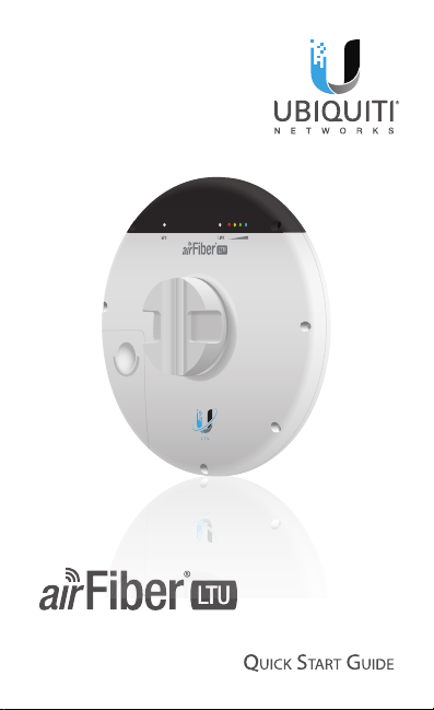
5 GHz TDD
Point-to-MultiPoint Radio
Model: AF-LTU
Page 2
Introduction
Thank you for purchasing the Ubiquiti Networks® airFiber®
AF‑LTU. This Quick Start Guide is designed to guide you
through installation and also includes warrantyterms.
Package Contents
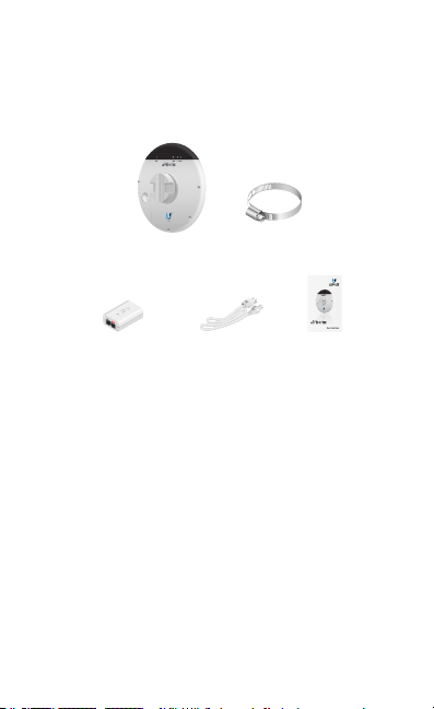
airFiber AF‑LTU
Gigabit PoE (24V, 1A)
with Mounting Bracket
TERMS OF USE: Ubiquiti radio devices must be professionally installed. Shielded Ethernet
cable and earth grounding must be used as conditions of product warranty. TOUGHCable™ is
designed for outdoor installations. It is the professional installer’s responsibility to follow local
country regulations, including operation within legal frequency channels, output power, and
Dynamic Frequency Selection (DFS) requirements.
Metal Strap
5 GHz TDD
Point-to-MultiPoint Radio
Power Cord Quick Start Guide
Model: AF-LTU
Antenna Compatibility
• The AF‑LTU is designed for use with the LTU‑Extend dish
antenna (not included).
• The AF‑LTU is also compatible with the following horn
antennas (not included):
• Prism®AP‑5‑30
• PrismAP‑5‑45
• PrismAP‑5‑60
• PrismAP‑5‑90
Page 3
Hardware Overview
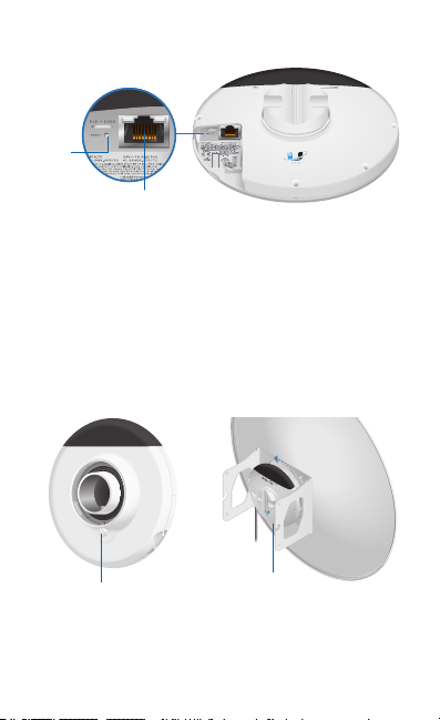
Reset
Button
Ethernet
Port
Ethernet Port This PoE port is used for handling all user traffic
and powering the device.
Reset Button To reset to factory defaults, press and hold the
Reset button for more than 10 seconds while the device is
already poweredon.
Release Button To detach the AF‑LTU from the antenna,
rotate the device counterclockwise while depressing the
Release Button. (To detach the AF‑LTU from a horn, rotate the
horn instead of the device.)
Release Button
Release Button
AF‑LTU Unmounted (Back View)
(not visible)
AF‑LTU Mounted on Antenna
Page 4
LEDs
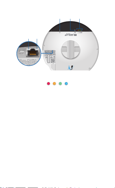
GPS SignalLINK
Ethernet
Ethernet
Activity
Link
Signal 1-4 These LEDs light the following colors when on:
• Signal 1 LED will light red when on.
1 2 3 4
• Signal 2 LED will light yellow when on.
• Signal 3 LED will light green when on.
• Signal 4 LED will light blue when on.
Bootup to airOS® When powering on, the GPS, Link, and
Signal 1‑4 LEDs light on. Once the CPU code takes over, the
GPS, Link, and Signal 1‑3 LEDs turn off. Signal 4 LED remains on
to indicate the boot sequence is underway.
Initializing airFiber Software When the airFiber application
begins to boot under airOS, the Signal 4 LED goes from solid on
to a 2.5 Hz flash. This continues until the AF‑LTU is fully booted.
Signal Level Once fully booted, the Signal 1‑4 LEDs act as a
bar graph showing how close the AF‑LTU is to ideal aiming. This
is auto‑scaled based on the link range, the antenna gains, and
the configured TX power of the remote AF‑LTU. Each Signal LED
has three possible states: On, Flashing, and Off. All Signal LEDs
would be solidly on in an ideal link. If the link has a 1 dB loss, the
Signal4 LED will flash; a 2 dB loss and the Signal 4 LED will turn
off. The full bar graph LED states are shown below.
Page 5

dB
0 ‑1 ‑2 ‑3 ‑4 ‑5 ‑6 ‑7 ‑8 ‑9 ‑10 ‑11 ‑12 ‑13
loss
1 F 0 0 0 0 0 0 0 0 0 0 0 0
1 1 1 F 0 0 0 0 0 0 0 0 0 0
1 1 1 1 1 F F 0 0 0 0 0 0 0
1 1 1 1 1 1 1 1 1 1 F F F 0
0 = Off, 1 = On, F = Flashing
Additional LEDs
LED State Status
Off No GPS Synchronization
GPS
Normal Flash* Non‑Operational (Weak Signal)
On Operational (Strong Signal)
Off RF Off
Short Flash* Syncing
LINK
Normal Flash* Beaconing
Long Flash* Registering
On Operational
Off No Ethernet Activity
Ethernet
Activity
Random Flash Ethernet Activity
Off
Ethernet
Link
On Gigabit Ethernet Link
10/100 Base‑T Link or
No Ethernet Link
* Short Flash (1:3 on/off cycle)
Normal Flash (1:1 on/off cycle)
Long Flash (3:1 on/off cycle)
Page 6

Installation Requirements
• Clear line of sight between airFiber radios
• Clear view of the sky for proper GPS operation
• Vertical mounting orientation
• Mounting point:
• At least 1 m below the highest point on the structure
• For tower installations, at least 3 m below the top of
thetower
• (Recommended) 2 Outdoor Gigabit PoE surge protectors
Note: For guidelines about grounding and lightning
protection, follow your local electrical regulatory
codes.
• Outdoor, shielded Category 6 (or above) cabling and
shielded RJ45 connectors are required for all wired Ethernet
connections.
Installation Overview
We recommend that you configure your paired AF‑LTU radios
before site installation. The overview below summarizes the
installation procedure, and the subsequent sections provide
detailed installation information.
• Connect the Gigabit PoE adapter to the Ethernet port of the
AF‑LTU and to your computer.
• Configure the AF‑LTU.
• At the installation site, install the antenna with the mounted
AF‑LTU radio (see the antenna’s Quick Start Guide for
installation instructions).
• Establish and optimize the RF link.
Page 7
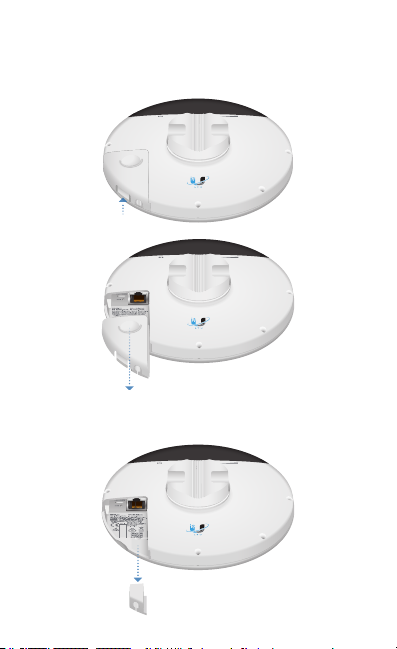
Connecting Power over Ethernet
1. Remove the port cover by lifting up the latch of the cover
and sliding the cover out.
2. Remove the rubber gasket from its slot in the housing of
the AF‑LTU.
Page 8
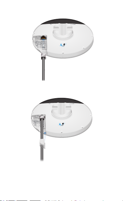
3. Connect an Ethernet cable to the Ethernet port.
4. Fit the rubber gasket over the Ethernet cable. Then slide
the gasket down the cable and reseat it in the slot.
*640-00345-01*
640-00345-01
Page 9
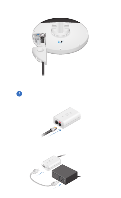
5. Replace the port cover.
6. Connect the other end of the Ethernet cable to the POE
port of the Gigabit PoE adapter.
WARNING: Use only the included adapter, model
POE-24V-AFX. Failure to do so can damage the unit
and void the product warranty.
7. Connect the Power Cord to the adapter’s power port.
Connect the other end of the Power Cord to a poweroutlet.
Page 10
airFiber Configuration
The instructions in this section explain how to access the
airFiber Configuration Interface and configure the following
settings:
• Wireless Mode Configure one AF‑LTU as the AP and the
other as the CPE.
• Frequency Setting The operating Frequency must be the
same on both the AP and the CPE.
This section also explains how to enable remote access to the
airFiber Configuration Interface using the Bluetooth interface
of the AF‑LTU.
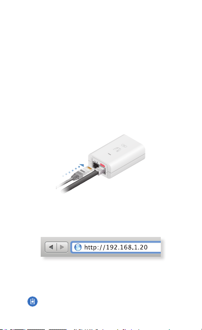
1. Connect an Ethernet cable from your computer to the LAN
port of the Gigabit PoE adapter.
2. Configure the Ethernet adapter on your computer with a
static IP address on the 192.168.1.x subnet.
3. Launch your web browser. Type http://192.168.1.20 in the
address field and press enter (PC) or return (Mac).
4. The login screen will appear. Enter ubnt in the Username
and Password fields. Select your Country and Language.
You must agree to the Terms of Use to use the product.
Click Login.
Note: U.S. product versions are locked to the U.S.
Country Code to ensure compliance with FCC
regulations.
Page 11
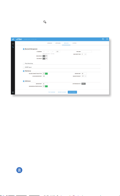
5. If you do not want to enable the Bluetooth interface for
remote management, go to step 14.
6. Click the Settings icon and then click the S ervices tab.
7. On the Services screen, select Bluetooth Management to
enable Bluetooth.
8. Specify the radio’s Bluetooth IP Address by entering its
last octet in the range of 2 to 14. (The range of valid IP
addresses is 172.20.10.2 to 172.20.10.14. The subnet is
pre‑assigned and cannot be changed.)
9. Select Web Server if you want mobile devices to have
access to the airFiber Configuration Interface via Bluetooth.
10. Select SSH Server if you want to enable secure
communications on the Bluetooth interface.
11. Enter a numeric Pin Code for the Bluetooth link (up to
16decimal digits).
12. Specify a Discovery Time in minutes. This is the length of
time that the Bluetooth link will remain discoverable after
each system reboot.
13. Click Save Changes and wait while the radio reboots.
Note: Following reboot, you will be able to connect
to the AF‑LTU via Bluetooth using a laptop or a
mobile device such as a smartphone. The radio’s
Bluetooth link will be named: AirFiber 5MX-xxxxxx,
where xxxxxx are six hexadecimal characters.
Page 12

14. Click the Wireless tab.
15. Configure the Basic Wireless Settings:
a. For one AF‑LTU, select AP PTP as the Wireless Mode. For
the other AF‑LTU, select CPE PTP as the Wireless Mode.
b. Enter a name in the Link Name field. This should be the
same on both the AP and the CPE.
c. Select your Country.
Note: The Country setting for U.S. product
versions is restricted to a choice of Canada, Puerto
Rico, or the U.S. to ensure compliance with FCC/
IC regulations.
d. Change the Distance Scale to be larger than the
anticipated distance between the AP and CPE.
e. If needed, change the Channel Bandwidth, Output Power
(EIRP), Antenna Gain, Cable Loss, RF RX Target Level
(APonly), Max TX Modulation, and Auto TX Modulation
settings.
16. Configure the Frequency Settings:
a. Set the desired Frequency. It needs to be the same for
both the AP and the CPE.
b. On the AP, set the Alternative Frequencies, which will be
used instead if DFS events are detected on the original
frequency. Up to three alternative frequencies can be
specified. The AP will automatically notify the CPEs of
these alternative frequencies.
17. Configure the Wireless Security:
a. Select WPA2-AES for the S ecurity mode.
b. Select PSK for the WPA Authentication mode.
c. In the WPA Preshared Key field, enter a combination of
alphanumeric characters (0‑9, A‑Z, or a‑z).
Note: Currently only ASCII mode is supported.
Page 13

18. Configure the Advanced wireless settings:
a. Select the CZ Len (contention zone length). This should
be the same for both the AP and the CPE.
b. Select the Duty Cycle on the AP.
c. Select the Frame Length. This should be the same on
both the AP and the CPE.
19. Click Save Changes.
20. Configure each airFiber radio with a unique IP address for
the Ethernet port:
a. Click the Network tab.
b. For the DLAN IP Address option:
‑ DHCP Keep the default, DHCP, to use DHCP
reservation on your router to assign a unique
IPAddress. You can also specify the DHCP Fallback IP
and DHCP Fallback Netmask to use in case the radio
fails to acquire an IP from the DHCP server.
‑ Static Change the IP Address, Netmask, and other
settings to make them compatible with your
network.
c. Enable the Management VLAN setting if needed.
d. Click Save Changes.
Repeat the instructions in the airFiber Configuration section on
the other AF‑LTU radio.
For details on the airFiber Configuration Interface, refer to the
airFiber AF‑LTU User Guide, available at:
www.ubnt.com/download/airfiber
Page 14
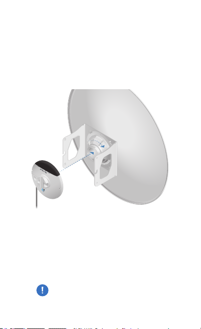
Hardware Installation
Mount to an LTU‑Extend Antenna
Follow the instructions in this section to mount the AF‑LTU to
an airFiber LTU‑Ex tend antenna.
1. Holding the AF‑LTU radio with the Port Cover facing you,
insert it into the Rear Housing and turn clockwise until it
locks in place.
2. Finish mounting the antenna assembly by following the
instructions in the antenna’s Quick Start Guide.
3. Connect the power using one of the following options:
• Using the included Gigabit PoE Adapter: Go to
Connecting to the PoE Adapter.
• Using a separate PoE switch: Connect the Ethernet
cable from the airFiber radio’s Ethernet port to a
PoE‑enabled Ethernet port on the switch.
WARNING: The switch port must comply with the
power specifications listed in the Specifications
section of this Quick Start Guide.
Page 15
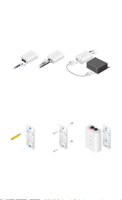
Connecting to the PoE Adapter
1. Connect the Ethernet cable from the AF‑LTU to the POE
port on the PoEAdapter.
2. Connect an Ethernet cable from your LAN to the LAN port
on the PoE Adapter.
3. Connect the Power Cord to the PoE Adapter, and then plug
the Power Cord into a power outlet.
Mounting the PoE Adapter (Optional)
1. Remove the PoE Mounting Bracket from the adapter, place
the bracket at the desired location, and mark the two holes.
2. Pre‑drill the holes if necessary, and secure the bracket
using two fasteners (not included).
3. Align the adapter’s slots with the tabs of the PoE Mounting
Bracket, and then slide the adapterdown.
Page 16
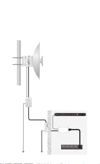
Surge Protection
For added protection, install two surge suppressors, such as
the Ubiquiti Ethernet Surge Protector, model ETH‑SP, at the
end of each link. Install the first surge protector within one
meter of the airFiber DATA port, and install the second surge
protector at the ingress point of the location housing the
wired network equipment.
AF‑LTU Radio
Mounted on
LTU‑Extend
Antenna
Max. 1 m
ETH‑SP
™
EdgeRouter
ETH‑SP
airFiber
PoE Adapter
Power Source
Page 17
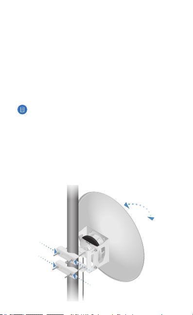
Alignment
Tip
• You may need to use additional hardware to compensate for
issues such as the improper orientation of a mounting pole
or significant elevation differences between airFiber radios.
Establishing a Link
Position the AP antenna to illuminate the desired area based
on topology and antenna beamwidth. The following section
features the LTU‑Extend antenna:
Note: The CPE does not transmit any RF signal until it
detects transmissions from the AP.
1. Visually aim the CPE at the AP. To adjust the CPE’s position,
adjust the azimuth and the elevation.
Adjust the azimuth:
a. Loosen the four Flange Nuts on the Carriage Bolts.
b. Rotate the antenna to point towards the other end of
the link.
c. Tighten the four Flange Nuts.
Page 18
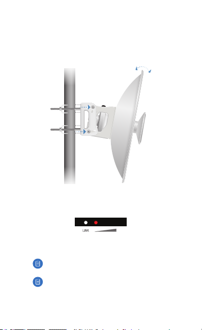
The elevation angle may be adjusted ±15°. Adjust the
elevation angle:
d. Loosen the four Hex Bolts on both sides of the antenna.
e. Pivot the antenna to the desired elevation.
f. Tighten the four Hex Bolts.
2. Check to see if a link is established. Ensure that the LINK
LED is solidly lit white and the Signal LEDs of the CPE are
displaying signal levels.
3. Aim the CPE at the AP to achieve the strongest signal level
on the AP.
Note: Refer to the Signal LEDs section for details on
the signal values.
Note: Maximum signal strength can best be
achieved by iteratively sweeping through both
azimuth and elevation.
Page 19

4. Repeat step 3 until you achieve an optimal link, with all
four Signal LEDs solidly lit. This ensures the best possible
data rate between the airFiber radios.
5. Lock the alignment on both airFiber antennas by
tightening all the nuts and bolts.
6. Observe the Signal LEDs of the CPE to ensure that the
values remain constant while tightening the nuts and
bolts. If any LED value changes during the locking process,
loosen the nuts and bolts, finalize the alignment of the CPE
antenna again, and retighten the nuts and bolts.
Page 20
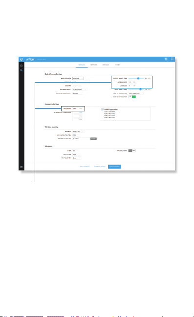
Installer Compliance Responsibility
Devices must be professionally installed and it is the
professional installer’s responsibility to make sure the device is
operated within local country regulatory requirements.
The Frequency, Output Power, Antenna Gain, and Cable Loss
fields are provided to the professional installer to assist in
meeting regulatory requirements.
Page 21

Specifications
Dimensions 155 x 155 x 65 mm
Weight 0.54 kg (1.20 lb)
Operating Frequency 4900‑6200 MHz
Operating RF Bandwidth 10/20/30/40/50 MHz
Networking Interface
Data Port
Conguration Port
LEDs (4) Signal Strength, GPS, RF Link,
Max. Power Consumption 17W
Power Supply 24V, 1A Gigabit PoE Adapter (Included)
Power Method Proprietary 24V Passive PoE
Supported Voltage Range 24 to 50VDC
Operating Temperature ‑40 to 55° C (‑40 to 131° F)
Mounting Integrated Pole‑Mount (Included)
Certications CE, FCC, IC
AF‑LTU
(1) 10/100/1000 Ethernet Port
Ethernet Link, Ethernet Activity
(6.10 x 6.10 x 2.56")
Bluetooth
Page 22

Safety Notices
1. Read, follow, and keep these instructions.
2. Heed all warnings.
3. Only use attachments/accessories specified by the manufacturer.
WARNING: Do not use this product in a location that can
be submerged by water.
WARNING: Avoid using this product during an electrical
storm. There may be a remote risk of electric shock from
lightning.
Electrical Safety Information
1. Compliance is required with respect to voltage, frequency, and current
requirements indicated on the manufacturer’s label. Connection to a
different power source than those specified may result in improper
operation, damage to the equipment or pose a fire hazard if the
limitations are not followed.
2. There are no operator serviceable parts inside this equipment. Ser vice
should be provided only by a qualified service technician.
3. This equipment is provided with a detachable power cord which has
an integral safety ground wire intended for connection to a grounded
safety outlet.
a. Do not substitute the power cord with one that is not the provided
approved type. Never use an adapter plug to connect to a 2‑wire
outlet as this will defeat the continuity of the grounding wire.
b. The equipment requires the use of the ground wire as a part of the
safety certification, modification or misuse can provide a shock
hazard that can result in serious injury or death.
c. Contact a qualified electrician or the manufacturer if there
are questions about the installation prior to connecting the
equipment.
d. Protective earthing is provided by Listed AC adapter. Building
installation shall provide appropriate short‑circuit backup
protection.
e. Protective bonding must be installed in accordance with local
national wiring rules and regulations.
Page 23

Limited Warranty
UBIQUITI NETWORKS, Inc (“UBIQUITI NETWORKS”) warrants that the
product(s) furnished hereunder (the “Product(s)”) shall be free from defects
in material and workmanship for a period of one (1) year from the date
of shipment by UBIQUITI NETWORKS under normal use and operation.
UBIQUITI NETWORKS’ sole and exclusive obligation and liability under
the foregoing warranty shall be for UBIQUITI NETWORKS, at its discretion,
to repair or replace any Product that fails to conform to the above
warranty during the above warranty period. The expense of removal and
reinstallation of any Product is not included in this warranty. The warranty
period of any repaired or replaced Product shall not extend beyond its
original term.
Warranty Conditions
The above warranty does not apply if the Product:
(I) has been modified and/or altered, or an addition made thereto,
except by Ubiquiti Networks, or Ubiquiti Networks’ authorized
representatives, or as approved by Ubiquiti Networks in writing;
(II) has been painted, rebranded or physically modified in any way;
(III) has been damaged due to errors or defects in cabling;
(IV) has been subjected to misuse, abuse, negligence, abnormal
physical, electromagnetic or electrical stress, including lightning
strikes, or accident;
(V) has been damaged or impaired as a result of using third party
firmware;
(VI) has no original Ubiquiti MAC label, or is missing any other original
Ubiquiti label(s); or
(VII) has not been received by Ubiquiti within 30 days of issuance of
the RMA.
In addition, the above warranty shall apply only if: the product has been
properly installed and used at all times in accordance, and in all material
respects, with the applicable Product documentation; all Ethernet cabling
runs use CAT5 (or above), and for outdoor installations, shielded Ethernet
cabling is used, and for indoor installations, indoor cabling requirements
are followed.
Returns
No Products will be accepted for replacement or repair without obtaining
a Return Materials Authorization (RMA) number from UBIQUITI NETWORKS
during the warranty period, and the Products being received at UBIQUITI
NETWORKS’ facility freight prepaid in accordance with the RMA process of
UBIQUITI NETWORKS. Products returned without an RMA number will not
be processed and will be returned freight collect or subject to disposal.
Information on the RMA process and obtaining an RMA number can be
found at: www.ubnt.com/support/warranty
Page 24

Disclaimer
EXCEPT FOR ANY EXPRESS WARRANTIES PROVIDED HEREIN, UBIQUITI
NETWORKS, ITS AFFILIATES, AND ITS AND THEIR THIRD PAR TY DATA,
SERVICE, SOFTWARE AND HARDWARE PROVIDERS HEREBY DISCLAIM
AND MAKE NO OTHER REPRESENTATION OR WARRANTY OF ANY KIND,
EXPRESS, IMPLIED OR STATUTORY, INCLUDING, BUT NOT LIMITED TO,
REPRESENTATIONS, GUARANTEES, OR WARRANTIES OF MERCHANTABILITY,
ACCURACY, QUALITY OF SER VICE OR RESULTS, AVAILABILITY,
SATISFACTORY QUALITY, LACK OF VIRUSES, QUIET ENJOYMENT, FITNESS
FOR A PARTICULAR PURPOSE AND NON‑INFRINGEMENT AND ANY
WARRANTIES ARISING FROM ANY COURSE OF DEALING, USAGE OR
TRADE PRACTICE IN CONNECTION WITH SUCH PRODUCTS AND SERVICES.
BUYER ACKNOWLEDGES THAT NEITHER UBIQUITI NETWORKS NOR
ITS THIRD PARTY PROVIDERS CONTROL BUYER’S EQUIPMENT OR THE
TRANSFER OF DATA OVER COMMUNICATIONS FACILITIES, INCLUDING
THE INTERNET, AND THAT THE PRODUCTS AND SER VICES MAY BE
SUBJECT TO LIMITATIONS, INTERRUPTIONS, DELAYS, CANCELLATIONS
AND OTHER PROBLEMS INHERENT IN THE USE OF COMMUNICATIONS
FACILITIES. UBIQUITI NETWORKS, ITS AFFILIATES AND ITS AND THEIR THIRD
PARTY PROVIDERS ARE NOT RESPONSIBLE FOR ANY INTERRUPTIONS,
DELAYS, CANCELLATIONS, DELIVERY FAILURES, DATA LOSS, CONTENT
CORRUPTION, PACKET LOSS, OR OTHER DAMAGE RESULTING FROM ANY
OF THE FOREGOING. In addition, UBIQUITI NETWORKS does not warrant
that the operation of the Products will be error‑free or that operation will
be uninterrupted. In no event shall UBIQUITI NETWORKS be responsible
for damages or claims of any nature or description relating to system
performance, including coverage, buyer’s selection of products (including
the Products) for buyer’s application and/or failure of products (including
the Products) to meet government or regulatory requirements.
Limitation of Liability
EXCEPT TO THE EXTENT PROHIBITED BY LOCAL LAW, IN NO EVENT WILL
UBIQUITI OR ITS SUBSIDIARIES, AFFILIATES OR SUPPLIERS BE LIABLE FOR
DIRECT, SPECIAL, INCIDENTAL, CONSEQUENTIAL OR OTHER DAMAGES
(INCLUDING LOST PROFIT, LOST DATA, OR DOWNTIME COSTS), ARISING
OUT OF THE USE, INABILITY TO USE, OR THE RESULTS OF USE OF THE
PRODUCT, WHETHER BASED IN WARRANTY, CONTRACT, TORT OR OTHER
LEGAL THEORY, AND WHETHER OR NOT ADVISED OF THE POSSIBILIT Y OF
SUCH DAMAGES.
Note
Some countries, states and provinces do not allow exclusions of implied
warranties or conditions, so the above exclusion may not apply to you.
You may have other rights that vary from country to country, state to
state, or province to province. Some countries, states and provinces do not
allow the exclusion or limitation of liability for incidental or consequential
damages, so the above limitation may not apply to you. EXCEPT TO
Page 25

THE EXTENT ALLOWED BY LOCAL LAW, THESE WARRANTY TERMS DO
NOT EXCLUDE, RESTRICT OR MODIFY, AND ARE IN ADDITION TO, THE
MANDATORY STATUTORY RIGHTS APPLICABLE TO THE LICENSE OF ANY
SOFTWARE (EMBEDDED IN THE PRODUCT) TO YOU. The United Nations
Convention on Contracts for the International Sale of Goods shall not apply
to any transactions regarding the sale of the Products.
Compliance
FCC
Changes or modifications not expressly approved by the party responsible
for compliance could void the user’s authority to operate the equipment.
This device complies with Part 15 of the FCC Rules. Operation is subject to
the following two conditions.
1. This device may not cause harmful interference, and
2. This device must accept any interference received, including
interference that may cause undesired operation.
This equipment has been tested and found to comply with the limits for a
Class B digital device, pursuant to Part 15 of the FCC Rules. These limits are
designed to provide reasonable protection against harmful interference in
a residential installation. This equipment generates, uses, and can radiate
radio frequency energy and, if not installed and used in accordance with
the instructions, may cause harmful interference to radio communications.
However, there is no guarantee that interference will not occur in a
particular installation. If this equipment does cause harmful interference
to radio or television reception, which can be determined by turning
the equipment off and on, the user is encouraged to try to correct the
interference by one or more of the following measures:
• Reorient or relocate the receiving antenna.
• Increase the separation between the equipment and receiver.
• Connect the equipment into an outlet on a circuit different from that to
which the receiver is connected.
• Consult the dealer or an experienced radio/TV technician for help.
Operations of this equipment in a residential area is likely to cause
harmful interference in which case the user will be required to correct the
interference at his own expense.
This radio transmitter FCC ID: SWX‑AF5LTU has been approved by FCC
to operate with the antenna types listed below with the maximum
permissible gain and required antenna impedance for each antenna type
indicated. Antenna types not included in this list, having a gain greater
than the maximum gain indicated for that type, are strictly prohibited for
use with this device.
Antenna Information: Dish antenna, Gain: 27 dBi; Horn antennas,
Gain:
13dBi, 19 dBi
Page 26

ISED Canada
CAN ICES‑3(B)/NMB‑3(B)
This device complies with ISED Canada licence‑exempt RSS standard(s).
Operation is subject to the following two conditions:
1. This device may not cause interference, and
2. This device must accept any interference, including interference that
may cause undesired operation of the device.
This radio transmitter (IC: 6545A‑AF5LTU) has been approved by ISED
Canada to operate with the antenna types listed below with the maximum
permissible gain and required antenna impedance for each antenna type
indicated. Antenna types not included in this list, having a gain greater
than the maximum gain indicated for that type, are strictly prohibited for
use with this device.
Antenna Information: Dish antenna, Gain: 27 dBi; Horn antenna, Gain: 19dBi
CAN ICES‑3(B)/NMB‑3(B)
Le présent appareil est conforme aux CNR d’ISDE Canada applicables aux
appareils radio exempts de licence. L’exploitation est autorisée aux deux
conditions suivantes :
1. l’appareil ne doit pas produire de brouillage;
2. l’appareil doit accepter tout brouillage radioélectrique subi, même si le
brouillage est susceptible d’en compromettre le fonctionnement.
Le présent émetteur radio (IC : 6545A‑AF5LTU) a été approuvé par ISDE
Canada pour l’exploitation avec l’antenne types énumérés ci‑dessous avec
le gain maximal admissible et requis l’impédance de l’antenne pour chaque
type d’antenne indiqué. Types d’antenne non inclus dans cette liste, ayant
un gain supérieur au gain maximal indiqué pour ce type, sont strictement
interdits pour une utilisation avec cet appareil.
Informations d’antenne : Antenne parabolique, Gain : 27 dBi; Antenne
corne, Gain : 19dBi
RF Exposure Warning
The antennas used for this transmitter must be installed to provide a
separation distance of at least 130 cm from all persons and must not be
located or operating in conjunction with any other antenna or transmitter.
Les antennes utilisées pour ce transmetteur doivent être installé en
considérant une distance de séparation de toute personnes d’au moins
130cm et ne doivent pas être localisé ou utilisé en conflit avec tout autre
antenne ou transmetteur.
Australia and New Zealand
Warning: This is a Class B product. In a domestic environment this
product may cause radio interference in which case the user may
be required to take adequate measures.
Page 27
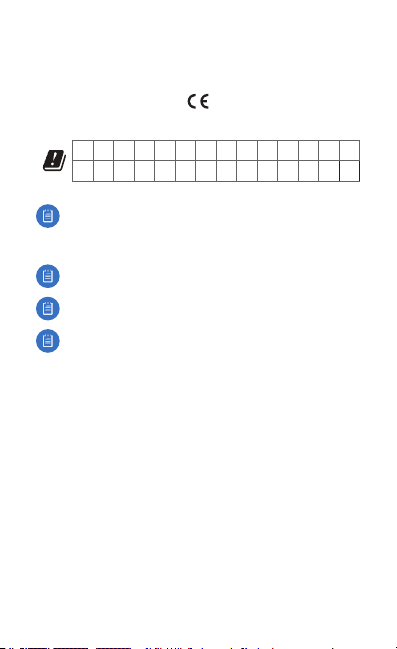
CE Marking
CE marking on this product represents the product is in compliance with all
directives that are applicable to it.
AT BE BG CY CZ DE DK EE EL ES FI FR HR HU
IE IT LV LT LU MT NL PL PT RO SE SI SK UK
BFWA (Broadband Fixed Wireless Access) members noted in blue
Note: This device meets Max. TX power limit per ETSI regulations.
The following apply to products that operate in the 5 GHz frequency range:
Note: This device is restricted to indoor use only when operating
in the 5150 ‑ 5350 MHz frequency range within all member states.
Note: All countries listed may operate at 30 dBm. BFWA member
states noted in blue may operate at 36 dBm.
Note: Operation in the 5.8 GHz frequency band is prohibited in
BFWA member states. Other countries listed may use the 5.8 GHz
frequency band.
Country List
Page 28

RoHS/WEEE Compliance Statement
English
European Directive 2012/19/EU requires that the equipment bearing
this symbol on the product and/or its packaging must not be disposed
of with unsorted municipal waste. The symbol indicates that this
product should be disposed of separately from regular household waste
streams. It is your responsibility to dispose of this and other electric and
electronic equipment via designated collection facilities appointed by the
government or local authorities. Correct disposal and recycling will help
prevent potential negative consequences to the environment and human
health. For more detailed information about the disposal of your old
equipment, please contact your local authorities, waste disposal service, or
the shop where you purchased the product.
Deutsch
Die Europäische Richtlinie 2012/19/EU verlangt, dass technische
Ausrüstung, die direkt am Gerät und/oder an der Verpackung mit diesem
Symbol versehen ist, nicht zusammen mit unsortiertem Gemeindeabfall
entsorgt werden darf. Das Symbol weist darauf hin, dass das Produkt
von regulärem Haushaltmüll getrennt entsorgt werden sollte. Es
liegt in Ihrer Verantwortung, dieses Gerät und andere elektrische
und elektronische Geräte über die dafür zuständigen und von der
Regierung oder örtlichen Behörden dazu bestimmten Sammelstellen zu
entsorgen. Ordnungsgemäßes Entsorgen und Recyceln trägt dazu bei,
potentielle negative Folgen für Umwelt und die menschliche Gesundheit
zu vermeiden. Wenn Sie weitere Informationen zur Entsorgung Ihrer
Altgeräte benötigen, wenden Sie sich bitte an die örtlichen Behörden oder
städtischen Entsorgungsdienste oder an den Händler, bei dem Sie das
Produkt erworben haben.
Page 29

Español
La Directiva 2012/19/UE exige que los equipos que lleven este símbolo en
el propio aparato y/o en su embalaje no deben eliminarse junto con otros
residuos urbanos no seleccionados. El símbolo indica que el producto
en cuestión debe separarse de los residuos domésticos convencionales
con vistas a su eliminación. Es responsabilidad suya desechar este y
cualesquiera otros aparatos eléctricos y electrónicos a través de los puntos
de recogida que ponen a su disposición el gobierno y las autoridades
locales. Al desechar y reciclar correctamente estos aparatos estará
contribuyendo a evitar posibles consecuencias negativas para el medio
ambiente y la salud de las personas. Si desea obtener información más
detallada sobre la eliminación segura de su aparato usado, consulte a las
autoridades locales, al servicio de recogida y eliminación de residuos de su
zona o pregunte en la tienda donde adquirió el producto.
Français
La directive européenne 2012/19/UE exige que l’équipement sur lequel
est apposé ce symbole sur le produit et/ou son emballage ne soit pas jeté
avec les autres ordures ménagères. Ce symbole indique que le produit
doit être éliminé dans un circuit distinct de celui pour les déchets des
ménages. Il est de votre responsabilité de jeter ce matériel ainsi que tout
autre matériel électrique ou électronique par les moyens de collecte
indiqués par le gouvernement et les pouvoirs publics des collectivités
territoriales. L’élimination et le recyclage en bonne et due forme ont pour
but de lutter contre l’impact néfaste potentiel de ce type de produits
sur l’environnement et la santé publique. Pour plus d’informations sur le
mode d’élimination de votre ancien équipement, veuillez prendre contact
avec les pouvoirs publics locaux, le service de traitement des déchets, ou
l’endroit où vous avez acheté le produit.
Italiano
La direttiva europea 2012/19/UE richiede che le apparecchiature
contrassegnate con questo simbolo sul prodotto e/o sull’imballaggio non
siano smaltite insieme ai rifiuti urbani non differenziati. Il simbolo indica
che questo prodotto non deve essere smaltito insieme ai normali rifiuti
domestici. È responsabilità del proprietario smaltire sia questi prodotti sia
le altre apparecchiature elettriche ed elettroniche mediante le specifiche
strutture di raccolta indicate dal governo o dagli enti pubblici locali. Il
corretto smaltimento ed il riciclaggio aiuteranno a prevenire conseguenze
potenzialmente negative per l’ambiente e per la salute dell’essere umano.
Per ricevere informazioni più dettagliate circa lo smaltimento delle vecchie
apparecchiature in Vostro possesso, Vi invitiamo a contattare gli enti
pubblici di competenza, il servizio di smaltimento rifiuti o il negozio nel
quale avete acquistato il prodotto.
Page 30

Declaration of Conformity
български [Bulgarian] С настоящото UBIQUITI NETWORKS декларира, че този тип
радиосъоръжение AF‑LTU е в съответствие с Директива 2014/53/ЕС. Цялостният текст
на ЕС декларацията за съответствие може да се намери на следния интернет адрес:
www.ubnt.com/compliance
Hrvatski [Croatian] UBIQUITI NETWORKS ovime izjavljuje da je radijska oprema tipa AF‑LTU u
skladu s Direktivom 2014/53/EU. Cjeloviti tekst EU izjave o sukladnosti dostupan je na sljedećoj
internetskoj adresi:
Čeština [Czech] Tímto UBIQUITI NETWORKS prohlašuje, že typ rádiového zařízení AF‑LTU je
v souladu se směrnicí 2014/53/EU. Úplné znění EU prohlášení o shodě je k dispozici na této
internetové adrese:
Dansk [Danish] Hermed erklærer UBIQUITI NETWORKS, at radioudstyrstypen AF‑LTU er i
overensstemmelse med direktiv 2014/53/EU. EU‑overensstemmelseserklæringens fulde tekst kan
findes på følgende internetadresse:
Nederlands [Dutch] Hierbij verklaar ik, UBIQUITI NET WORKS, dat het type radioapparatuur
AF‑LTU conform is met Richtlijn 2014/53/EU. De volledige tekst van de EU‑conformiteitsverklaring
kan worden geraadpleegd op het volgende internetadres:
English
compliance with Directive 2014/53/EU. The full text of the EU declaration of conformity is
available at the following internet address: www.ubnt.com/compliance
Eesti keel [Estonian] Käesolevaga deklareerib UBIQUITI NETWORKS, et käesolev raadioseadme
tüüp AF‑LTU vastab direktiivi 2014/53/EL nõuetele. ELi vastavusdeklaratsiooni täielik tekst on
kättesaadav järgmisel internetiaadressil:
Suomi [Finnish] UBIQUITI NETWORKS vakuuttaa, että radiolaitetyyppi AF‑LTU on direktiivin
2014/53/EU mukainen. EU‑vaatimustenmukaisuusvakuutuksen täysimittainen teksti on saatavilla
seuraavassa internetosoitteessa:
Français [French] Le soussigné, UBIQUITI NETWORKS, déclare que l’équipement radioélectrique
du type AF‑LTU est conforme à la directive 2014/53/UE. Le texte complet de la déclaration UE de
conformité est disponible à l’adresse internet suivante:
Deutsch [German] Hiermit erklärt UBIQUITI NET WORKS, dass der Funkanlagentyp AF‑LTU der
Richtlinie 2014/53/EU entspricht. Der vollständige Text der EU‑Konformitätserklärung ist unter der
folgenden Internetadresse verfügbar:
Ελληνικά [Greek] Με την παρούσα ο/η UBIQUITI NETWORKS, δηλώνει ότι ο ραδιοεξοπλισμός
AF‑LTU πληροί την οδηγία 2014/53/ΕΕ. Το πλήρες κείμενο της δήλωσης συμμόρφωσης ΕΕ
διατίθεται στην ακόλουθη ιστοσελίδα στο διαδίκτυο:
Magyar [Hungarian] UBIQUITI NETWORKS igazolja, hogy a AF‑LTU típusú rádióberendezés
megfelel a 2014/53/EU irányelvnek. Az EU‑megfelelőségi nyilatkozat teljes szövege elérhető a
következő internetes címen:
Íslenska [Icelandic] Hér með lýsir UBIQUITI NETWORKS yfir því að AF‑LTU er í samræmi
við grunnkröfur og aðrar kröfur, sem gerðar eru í tilskipun 2014/53/EU. Fullur texti ESB
samræmisyfirlýsing er að finna á eftirfarandi netfangi:
Italiano [Italian] Il fabbricante, UBIQUITI NETWORKS, dichiara che il tipo di apparecchiatura
radio AF‑LTU èconforme alla direttiva 2014/53/UE. Il testo completo della dichiarazione di
conformità UE è disponibile al seguente indirizzo Internet:
Latvių kalba [Latvian] Ar šo UBIQUITI NETWORKS dek larē, ka radioiekārta AF‑LTU atbilst
Direktīvai 2014/53/ES. Pilns ES atbilstības deklarācijas teksts ir pieejams šādā interneta vietnē:
www.ubnt.com/compliance
Lietuvių kalba [Lithuanian] Aš, UBIQUITI NETWORKS, patvirtinu, k ad radijo įrenginių tipas AF‑LTU
atitinka Direktyvą 2014/53/ES. Visas ES atitikties deklaracijos tekstas prieinamas šiuo interneto
adresu:
www.ubnt.com/compliance
www.ubnt.com/compliance
www.ubnt.com/compliance
Hereby, UBIQUITI NETWORKS declares that the radio equipment type
www.ubnt.com/compliance
www.ubnt.com/compliance
www.ubnt.com/compliance
www.ubnt.com/compliance
www.ubnt.com/compliance
www.ubnt.com/compliance
www.ubnt.com/compliance
www.ubnt.com/compliance
www.ubnt.com/compliance
www.ubnt.com/compliance
AF‑LTU
is in
Page 31

Malti [Maltese]
B’dan, UBIQUITI NETWORKS, niddikjara li dan it‑tip ta’ tagħmir tar‑radju
huwa konformi mad‑Direttiva 2014/53/UE. Id‑dikjarazzjoni tal‑konformità tista’ tiġi kkonsultata
minn www.ubnt.com/compliance
Norsk [Norwegian]
med de grunnleggende krav og øvrige relevante krav i direktiv 2014/53/EU. Den
fulle teksten til EU‑samsvarserklæringen er tilgjengelig på følgende internettadresse:
www.ubnt.com/compliance
Polski [Polish] UBIQUITI NETWORKS niniejszym oświadcza, że typ urządzenia radiowego AF‑LTU
jest zgodny z dyrektywą 2014/53/UE. Pełny tekst deklaracji zgodności UE jest dostępny pod
następującym adresem internetowym:
Português [Portuguese] O(a) abaixo assinado(a) UBIQUITI NETWORKS declara que o presente
tipo de equipamento de rádio AF‑LTU está em conformidade com a Diretiva 2014/53/UE. O
texto integral da declaração de conformidade está disponível no seguinte endereço de Internet:
www.ubnt.com/compliance
Română [Romanian] Prin prezenta, UBIQUITI NETWORKS declară că tipul de echipamente
radio AF‑LTU este în conformitate cu Directiva 2014/53/UE. Textul integral al declarației UE de
conformitate este disponibil la următoarea adresă internet:
Slovenčina [Slovak]
súlade so smernicou 2014/53/EÚ. Úplné EÚ vyhlásenie o zhode je k dispozícii na tejto internetovej
adrese:
Slovenščina [Slovenian]
Direktivo 2014/53/EU. Celotno besedilo izjave EU o skladnosti je na voljo na naslednjem spletnem
naslovu: www.ubnt.com/compliance
Español [Spanish] Por la presente, UBIQUITI NETWORKS declara que el tipo de equipo
radioeléctrico AF‑LTU es conforme con la Directiva 2014/53/UE. El texto completo de
la declaración UE de conformidad está disponible en la dirección Internet siguiente:
www.ubnt.com/compliance
Svenska [Swedish] Härmed försäkrar UBIQUITI NETWORKS att denna typ av radioutrustning
AF‑LTU överensstämmer med direktiv 2014/53/EU. Den fullständiga texten till EU‑försäkran om
överensstämmelse finns på följande webbadress:
Online Resources
Website www.ubnt.com
Support help.ubnt.com
Community community.ubnt.com
Downloads downloads.ubnt.com
UBIQUITI NETWORKS erklærer herved at utstyret
www.ubnt.com/compliance
UBIQUITI NETWORKS
www.ubnt.com/compliance
UBIQUITI NETWORKS potrjuje, da je tip radijske opreme
www.ubnt.com/compliance
týmto vyhlasuje, že rádiové zariadenie typu AF‑LTU je v
www.ubnt.com/compliance
AF‑LTU
er i samsvar
AF‑LTU
AF‑LTU
skladen z
Page 32

www.ubnt.com
Ubiquiti Networks, Inc.
685 Third Avenue, 27th Floor
New York, NY 10017
USA
©2017 Ubiquiti Networks, Inc. All rights reserved. Ubiquiti, Ubiquiti Networks, the
Ubiquiti U logo, the Ubiquiti beam logo, airFiber, airOS, Prism, and TOUGHCable
are trademarks or registered trademarks of Ubiquiti Networks, Inc. in the United
States and in other countries. All other trademarks are the property of their
respective owners. AI122217
 Loading...