

Page 1

MaxiScan 3300
Installation Guide
Edition 1.0
valid for MaxiScan 3300 with S/N greater than 01000
August 1997
MS/3300/IG/10/E/970831
Page 2
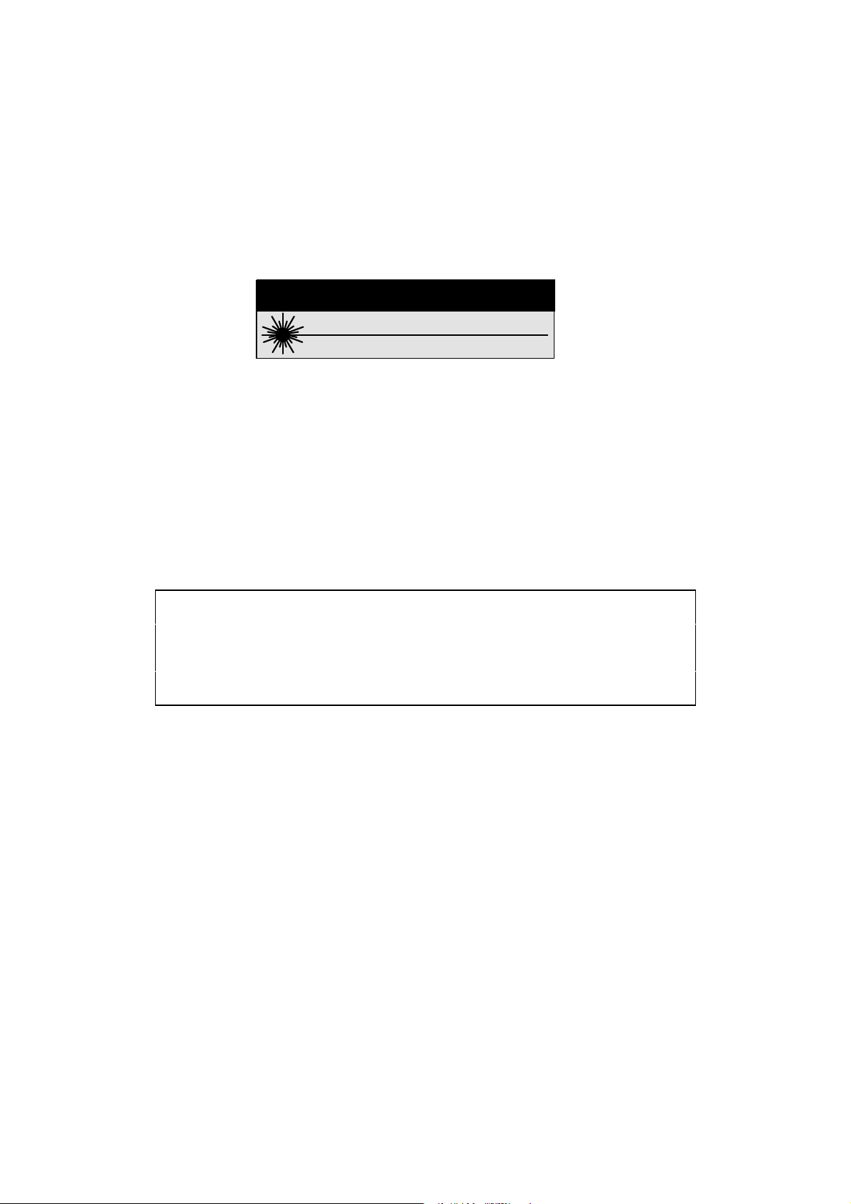
Notice
#!54)/.
LASER LIGHT - DO NOT STARE INTO BEAM
660 nm LASER DIODE - 1.0 MILLIWATT MAX OUTPUT
CLASS II LASER PRODUCT
English
Deutsch
Français
Italiano
Svenska
USA DHHS Standard 21CFR 1040.10 and 1040.11: Class II Laser Product
IEC 825: CLASS 2 LASER PRODUCT
LASER LIGHT—DO NOT STARE INTO BEAM
IEC 825: LASERPRODUKT DER KLASSE 2
LASERSTRAHLEN—NICHT DIREKT IN DEN LASERSTRAHL SCHAUEN
IEC 825: PRODUIT LASER DE CLASSE 2
LUMIERE LASER—NE PAS REGARDER DANS LE FAISCEAU
IEC 825: PRODOTTO LASER CLASSE 2
RAGGIO LASER - NON RESTARE ESPOSTO AI RAGGI
IEC 825: LASERPRODUKT KLASS 2
LASERLJUS—STIRRA INTE MOT STRÅLEN
The MaxiScan products described in this manual comply with CE directives for
electromagnetic emission levels and electrical immunity in industrial environments.
Warning
This apparatus is a Class A apparatus. In a residential environment this apparatus may
cause radio frequency interference. In this case, the user may be asked to take appropriate
measures.
The MaxiScan 3300 will operate in complete safety when used as specified in official UBI
MaxiScan 3300 documentation.
Protective eyewear is recommended when working in the laser field.
The information contained in this manual is for informational purposes only and is subject to
change without notice. No part of this manual may be copied or reproduced in any manner without
the prior written permission of United Barcode Industries.
MaxiScan products are covered by patents issued or pending in the USA and other countries.
MaxiScan is a trademark of United Barcode Industries.
MS/3300/IG/10/E/970831
Page 3
Scanner Technology Center
DECLARATION OF CONFORMITY
We,
UBI Scanner Technology Center
Immeuble Le Naurouze, Rue Carmin
Voie No.3, Innopole - BP 187
31676 Labège Cedex
France
1
declare under our sole responsibility
MaxiScan 3300
to which this declaration relates
is (are) in conformity with the following standards:
Emission: EN 50081-2 (1995)
EN 55022 (1987) Class A
Immunity: EN 50082-2 (1995)
Safety: EN 60950 (1993)
IEC 950
following the provisions of Directives
89/336/EEC
73/23/EEC
Toulouse 04/03/1997
that the product(s)
...................................................................
Sven Skarendahl
President
1
UBI assumes no responsibility as regards fulfilling the CE Directive if the product(s) is (are) handled,
modified or installed in other manners than those described in UBI’s manuals.
UBI Scanner Technology Center
Voie No.3, Innopole - BP 187, 31676 Labège Cedex, France
Immeuble Le Naurouze, Rue Carmin
Tel: +33 (0)5 61 39 98 58 • Fax: +33 (0)5 61 39 20 00
MS/3300/IG/10/E/970831 iii
Page 4

iv MS/3300/IG/10/E/970831
Page 5

What you are going to do . . .
This Installation Guide tells you how to install the MaxiScan 3300 to operate successfully in
most working situations.
You will then probably need to use the EasySet System configuration software to customize
the MaxiScan 3300 setup parameters for your application—section 5 (
MaxiScan 3300
) tells you how to do this.
Step by step how to install and set up your MaxiScan 3300
1 Check you have everything you need...........................................................1-1
2 Decide what's best for your application.........................................................2-1
3 Switch off the host system and connect up your MaxiScan 3300 .................3-1
4 Power up the MaxiScan 3300 .......................................................................4-1
5 Setting up your MaxiScan 3300 ....................................................................5-1
Additional information is provided in the Appendix
A Technical characteristics.............................................................................. A-1
Setting up your
B MaxiScan 3300 cable connector.................................................................. B-1
C MaxiScan Connexion System (MCS)...........................................................C-1
D Standard RS-232 C cable............................................................................ D-1
E Input/output synchronization ........................................................................ E-1
F If you have a problem . . . .............................................................................F-1
G Test codes ...................................................................................................G-1
MS/3300/IG/10/E/970831 v
Page 6

What you are going to do . . .
vi MS/3300/IG/10/E/970831
Page 7

1 Check you have everything you need
Checklist of items for your installation
all systems
options
The minimum configuration for the EasySet System configuration software is Windows™
3.11 running on a 486 PC with 8 MB RAM.
MaxiScan 3300
EasySet System
this
7-25 VDC mains power supply adapter
MaxiScan Connexion System unit
standard RS-232 C cable (also used to download setup commands from the
adjustable stand
MaxiScan 3300 Installation Guide
EasySet System
configuration software
configuration software)
MS/3300/IG/10/E/970831 1-1
Page 8

1. Check you have everything you need
MS/3300/IG/10/E/9708311-2
Page 9
2 Decide what’s best for your application
Safety first !!!
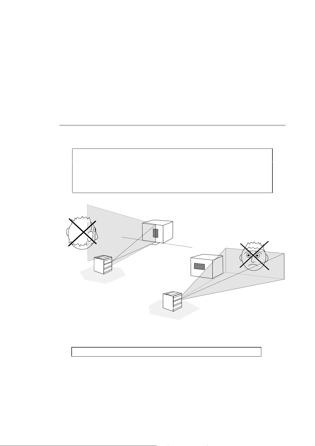
As for all laser products, prolonged viewing into direct laser light may damage
people's eyes—remember this when you decide where to install your MaxiScan 3300 !
The MaxiScan 3300 will operate in complete safety when used as specified in this
Installation Guide.
Do not try to dismount the MaxiScan 3300 and always use the scanner only as
described in official MaxiScan 3300 documentation.
NO !!!
specular reflection
NO !!!
direct beam
specular reflection = laser light reflected directly perpendicular to the reflective surface
MS/3300/IG/10/E/970831 2-1
Page 10
2. Decide what’s best for your application
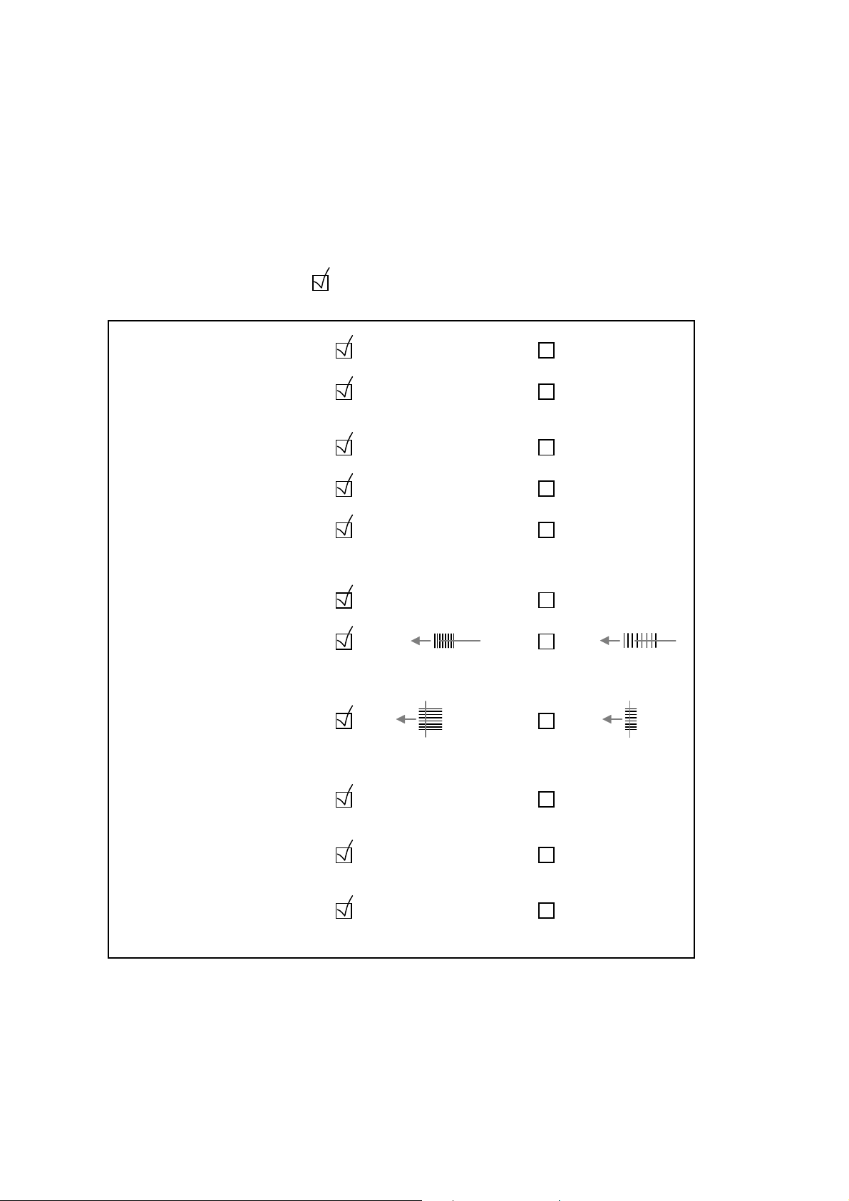
What’s best for labels
label quality
label printing
label surface
label location
label orientation
label size
picket pass-through applications
overall barcode width
ladder pass-through applications
length of bars (barcode height)
good quality, undamaged
thermal transfer, direct
thermal, modern ink-jet
matt
same location
all codes same orientation
(a slight skew is good as it
prevents specular reflection)
same size
narrow
(more scans, higher
pass-through speeds)
long
(more scans, read over
whole code area)
variable quality
fuzzy printing,
dot-matrix, . . .
glossy, reflective
different locations
different orientations,
excessive tilt, pitch or
skew
different sizes
wide
short
contrast
black : white ratio (minimum = 25%)
barcode density (resolution)
narrow bar width
quiet zone
empty margin at start / end of code
high contrast
medium density
at least 10 * "X" dimension
(narrow bar width)
low contrast
low / high density
less than
10 * "X" dimension
MS/3300/IG/10/E/9708312-2
Page 11
2. Decide what’s best for your application
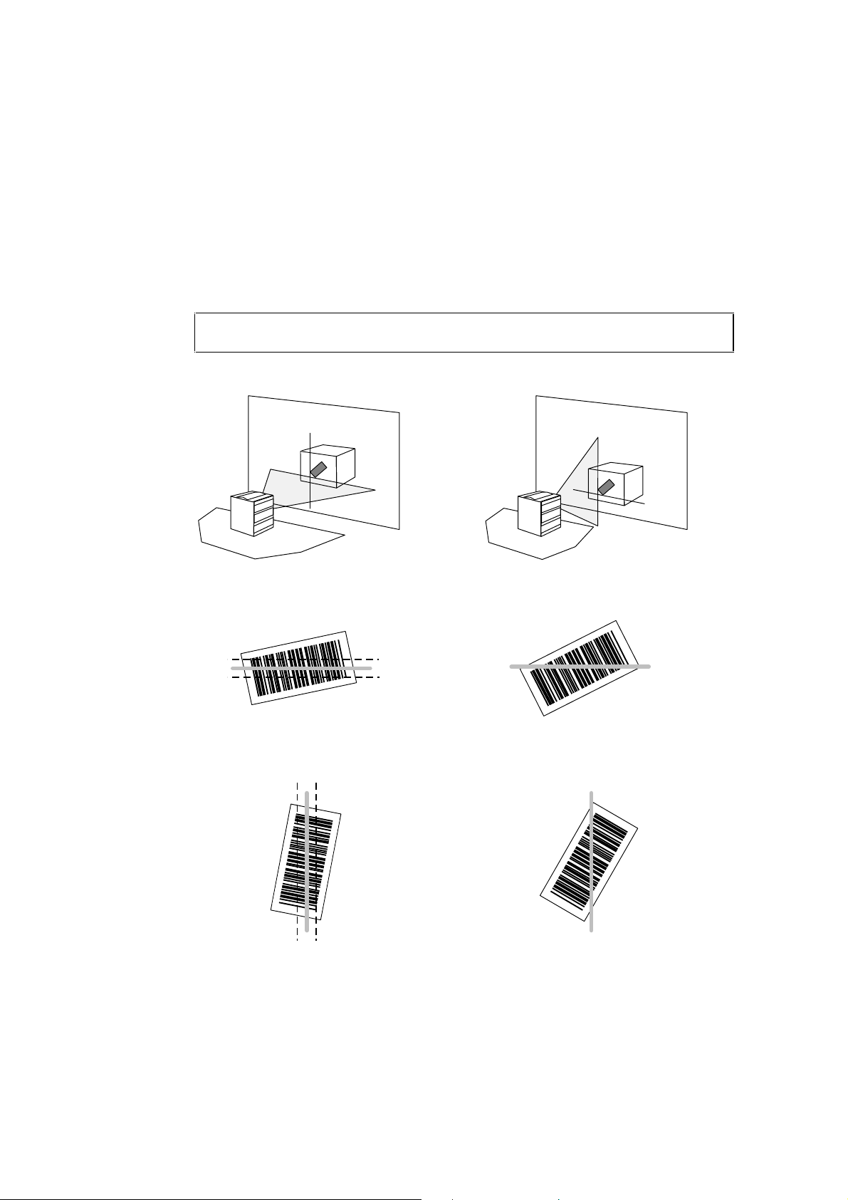
Difficult reading situations—Tilt
tilt reduces the number of effective scans for the bar code—heavy tilt prevents reading as
the scan line can not cover all the bars
read OK
read OK
MS/3300/IG/10/E/970831 2-3
no read
no read
Page 12
2. Decide what’s best for your application
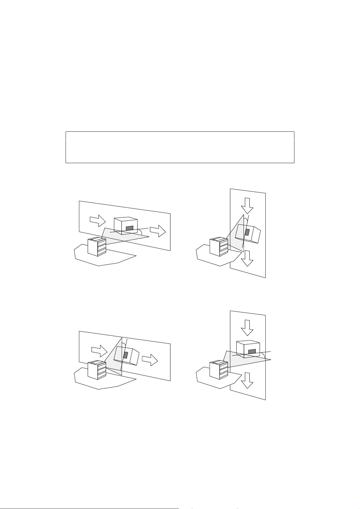
Difficult reading situations—Pitch
• pitch reduces bar width and is much more critical for high-density bar codes
• reading may be possible with a pitch angle up to ± 70°
• the greater the pitch angle, the more difficult it is to read
Picket fence
Ladder
MS/3300/IG/10/E/9708312-4
Page 13
2. Decide what’s best for your application
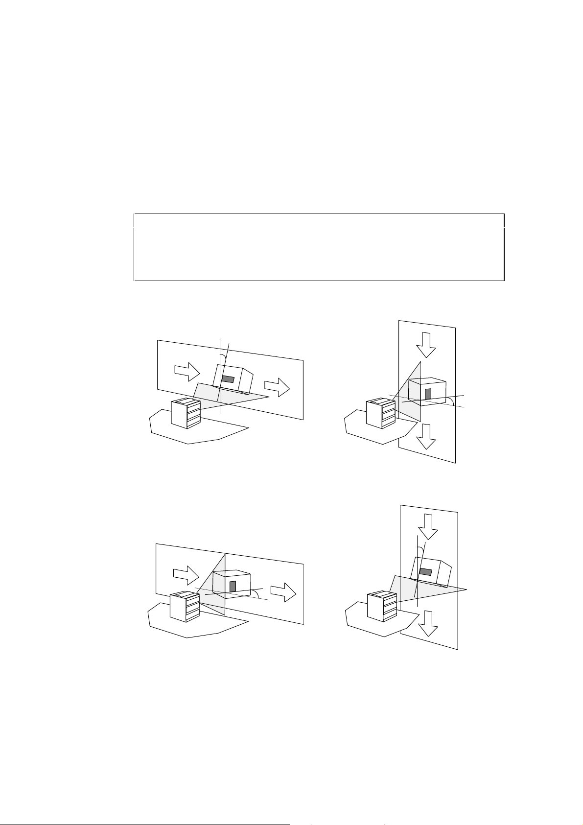
Difficult reading situations—Skew
• skew reduces bar height
• reading may be possible with a skew angle up to ± 40°
• the greater the skew angle, the more difficult it is to read
• a slight skew (scanner or labels) is good as it prevents 90° specular reflection
Picket fence
Ladder
MS/3300/IG/10/E/970831 2-5
Page 14

2. Decide what’s best for your application
General remarks
As a general rule, keep your application simple and consistent.
Wait until you have tested your setup before you install the MaxiScan 3300
permanently.
environment
cables and connections
optional adjustable stand
I/O synchronization
symbologies
• make sure that your operating environment is suitable for your
MaxiScan 3300 model—refer to the product specifications in
Appendix A
• remember to take into account the length of the operating
cables and power supply cable when you set up your
MaxiScan 3300
• using the adjustable stand is more flexible than fixing the
MaxiScan 3300 directly to the work surface—refer to the
product specifications in Appendix A
• external input synchronization devices can be used to activate
the MaxiScan 3300—they ensure longer life for the motors and
laser diode and allow you to detect unsuccessful read attempts
• the MaxiScan 3300 can also send a synchronization output to
control external devices according to the read result
• refer to Appendix E if your application uses external
synchronization devices
• use standard symbologies best suited to your application—
some symbologies (Interleaved 2 of 5 for example) are less
reliable than others
• try to use as few symbologies as possible
specular reflection
• fixed barcode lengths and check digits increase reading
efficiency and security
• slightly skew the scanner or labels to avoid 90° specular
reflection (label exactly perpendicular to scanner) in any part of
the scan
MS/3300/IG/10/E/9708312-6
Page 15
number of scans
picket fence
2. Decide what’s best for your application
• a good read usually requires a minimum of 5 scans
• generally more scans per code in pass-through applications
than with ladder reading
ladder
reading distance
depth of field
• generally fewer scans per code in pass-through applications
than with picket fence reading
• read over whole code height—good for high-speed passthrough with variable label quality and different label positions
• high density bar codes require a shorter reading distance than
low density codes—reading distance is less critical for
medium-density codes
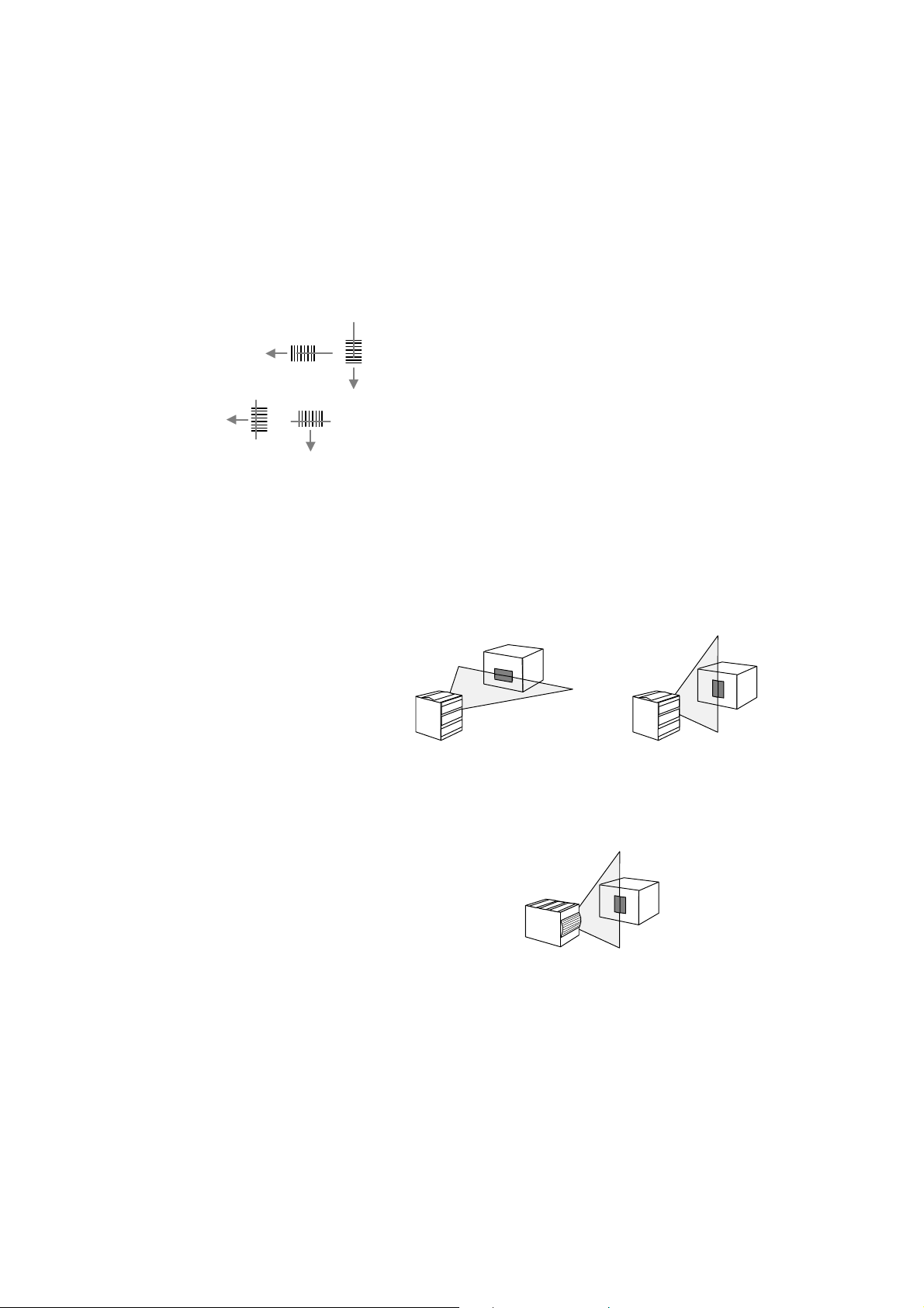
• there is more depth of field when the laser beam is horizontal
with regard to the MaxiScan 3300:
more depth of field less depth of field
if your application mostly needs a vertical beam, it is better to
install the MaxiScan 3300 on its side:
more depth of field
MS/3300/IG/10/E/970831 2-7
Page 16
2. Decide what’s best for your application
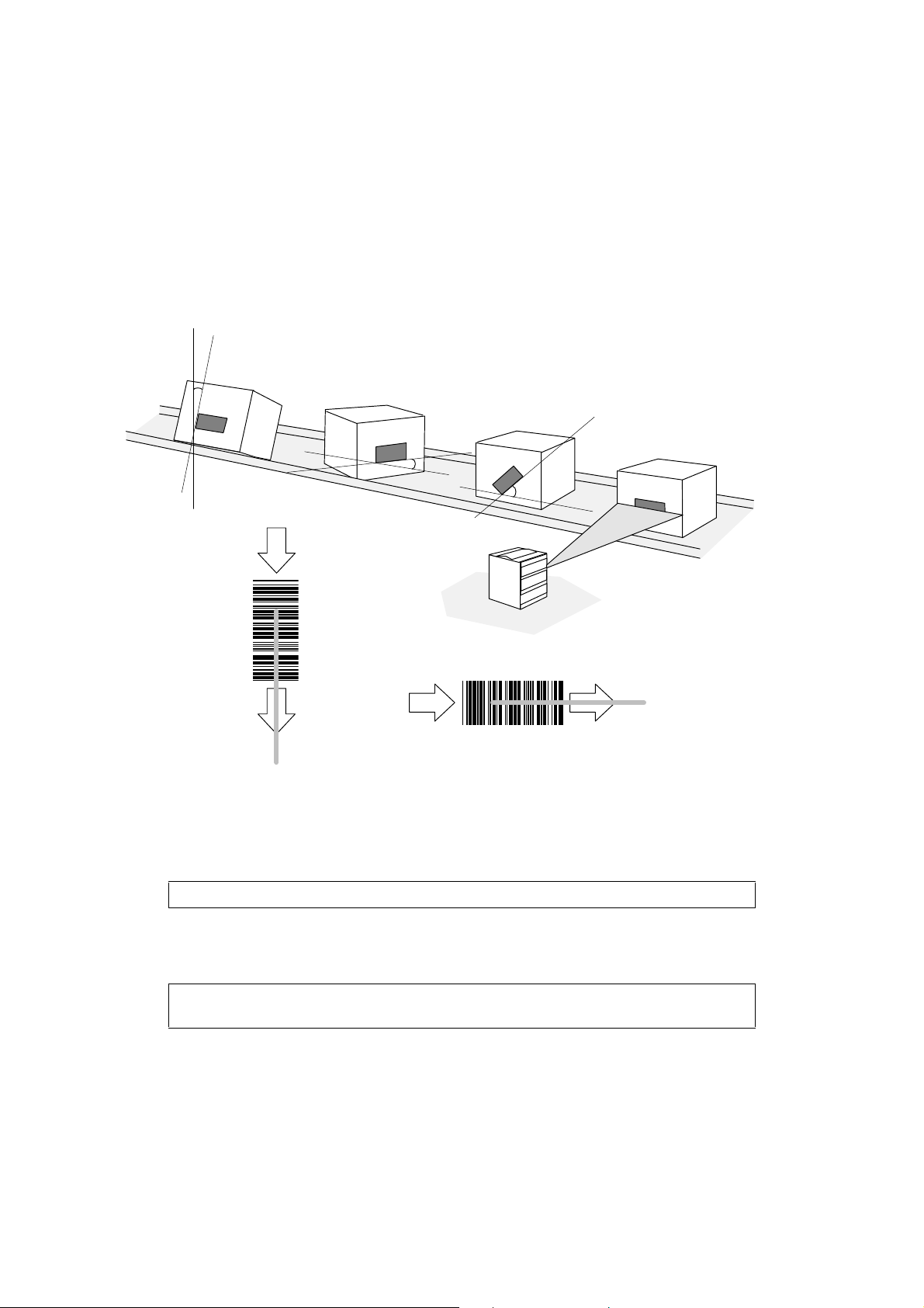
Picket fence reading
skew
pitch
tilt
picket fence
•
number of scans
Example: scan width = 20 cm code width = 10 cm scan rate = 450 scans / sec
The code width value will vary slightly according to the degree of tilt and pitch.
• increase the scan width (adjust the reading distance) and decrease the code width and
pass-through speed to increase the number of scans
Remain within the product specifications for reading distance and barcode density
provided in Appendix A.
= [ (
scan width - code width
conveyor speed = 1 meter / sec (100 cm / sec)
[ ( 20 - 10 ) * 450 / 100 ] - 2 = 43 so there will be 43 full scans on the code
) x
scan rate
/
pass-through speed
MS/3300/IG/10/E/9708312-8
] - 2
Page 17
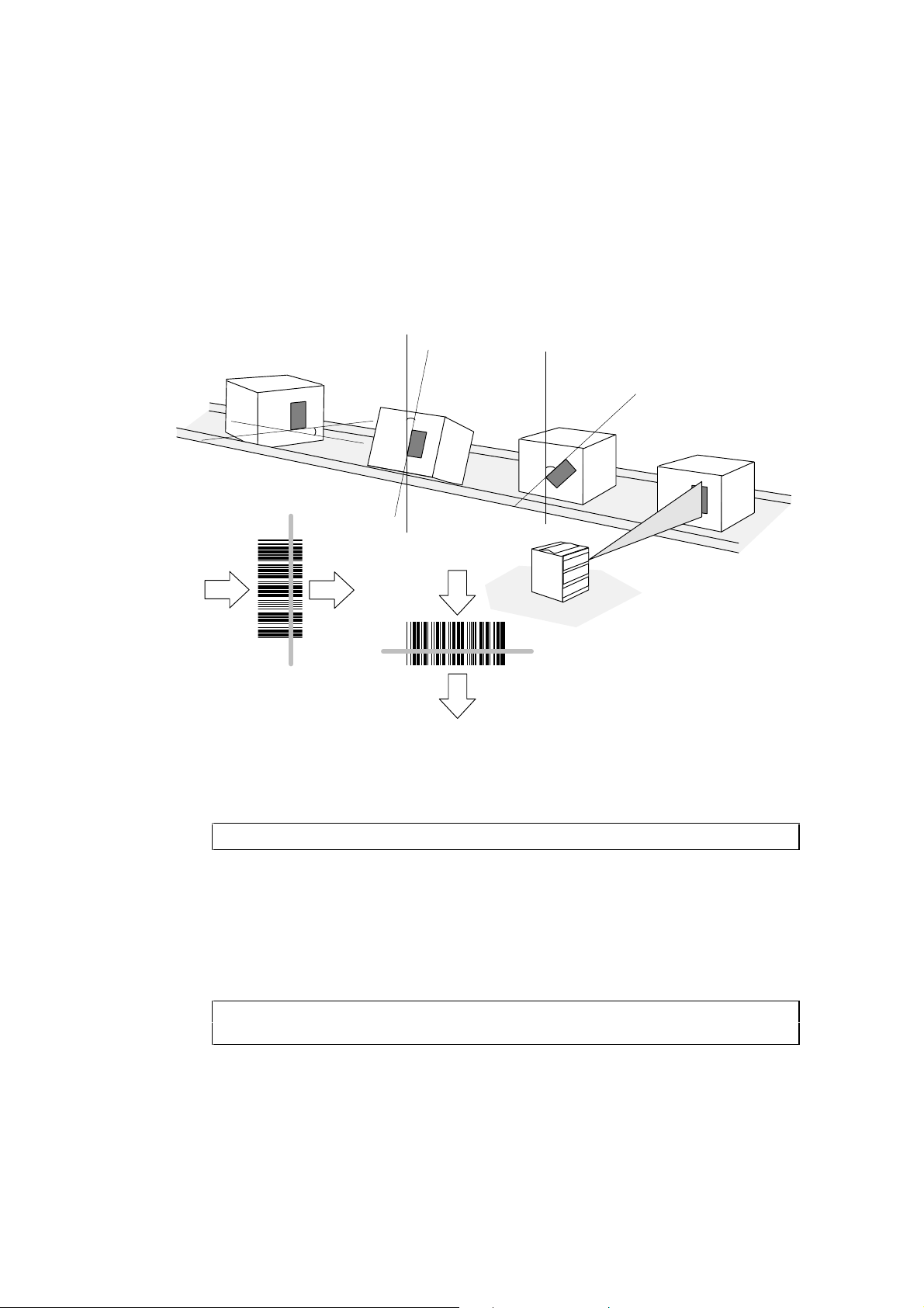
Ladder reading
skew
2. Decide what’s best for your application
pitch
tilt
ladder
•
number of scans
Example: code height = 2.5 cm conveyor speed = 1 meter/sec (100 cm / sec)
The code height value will vary slightly according to the degree of tilt and skew.
• increase the code height and decrease the pass-through speed to increase the number
of scans
•
minimum code height
if we suppose that 5 scans is a good minimum, the formula becomes:
Remain within the product specifications for reading distance and barcode density
provided in Appendix A.
MS/3300/IG/10/E/970831 2-9
min code height
= [ (
code height
scan rate = 450 scans / sec
[ (2.5 / 100) * 450 ] - 2 = 9.25 so there will be 9 full scans on the code
=
pass-through speed
=
pass-through speed
/
pass-through speed
x (
number of scans
x 7 /
) x
scan rate
scan rate
] - 2
+ 2) /
scan rate
Page 18
2. Decide what’s best for your application
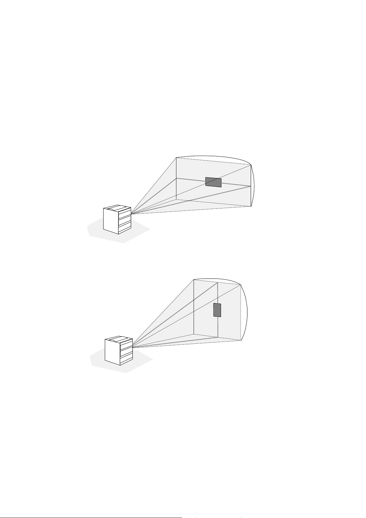
Scan angles
HORIZONTALSCANANGLEp
VERTICALSWEEPANGLEp
p
p
p
VERTICALSCANANGLEp
p
HORIZONTALSWEEPANGLEp
MS/3300/IG/10/E/9708312-10
Page 19
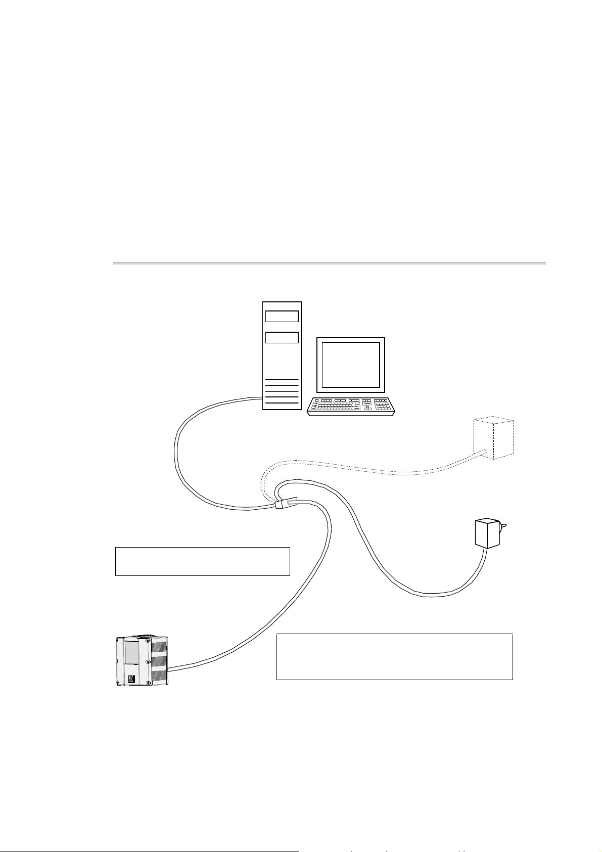
3 Switch off the host system and
connect up your MaxiScan 3300
Direct connection—RS-232 C, RS-422, RS-485
Switch off the host system.
I/O synchronization
device
Connect up the cables.
ô
You will have to adapt the cables to suit
your application—see the Appendix.
Plug in the mains power supply adapter.
í
M Do not switch on the host system until you
have connected up and plugged in the mains power
supply adapter.
MS/3300/IG/10/E/970831 3-1
7-25 VDC
power supply
Page 20
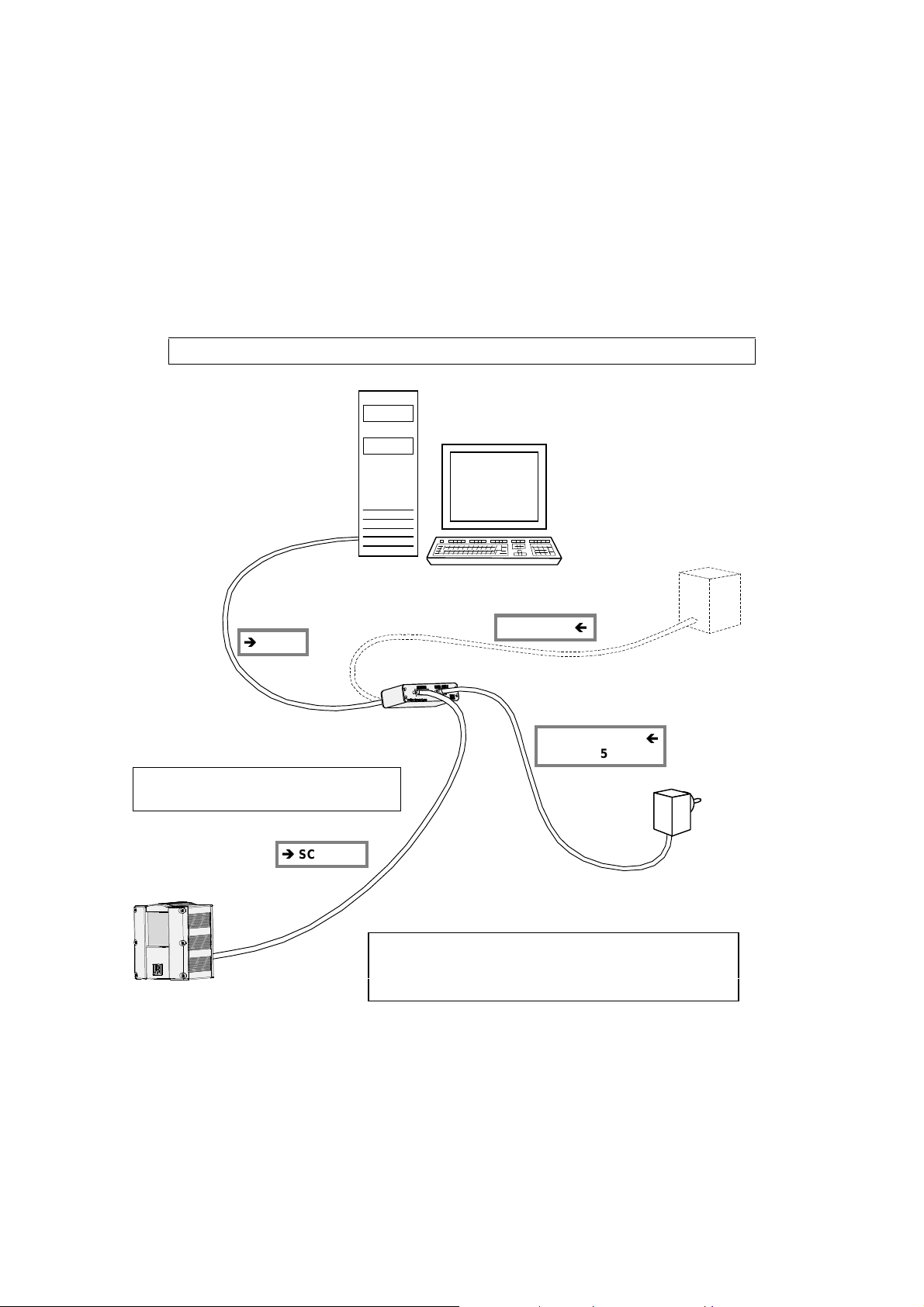
3. Switch off the host system and connect up your MaxiScan 3300
MCS connection unit—RS-232 C, RS-422, RS-485, Current Loop
The MaxiScan Connexion System unit is necessary for Current Loop applications.
Switch off the host system.
I/O synchronization
device
Ð
HOST
Connect up the cables.
ô
You may need to adapt the cables to
suit your application—see the Appendix.
Ð
SCANNER
SYNCHROS
Plug in the mains power supply adapter.
í
Ï
POWER SUPPLY
7-25 V
Ï
M Do not switch on the host system until you have
connected up and plugged in the mains power
supply adapter.
MS/3300/IG/10/E/9708313-2
Page 21
4 Power up the MaxiScan 3300
Laser safety recommendations
The MaxiScan 3300 will operate in complete safety when used as specified in this
Installation Guide.
As for all laser products, avoid staring directly into the laser light beam for long
periods of time—prolonged viewing into direct laser light may damage your eyes.
Do not try to dismount the MaxiScan 3300 and always use the scanner only as
described in official MaxiScan 3300 documentation.
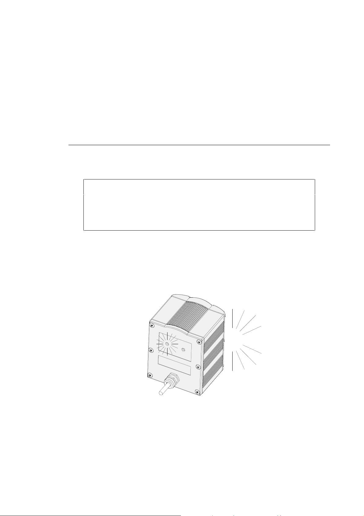
Plug in and power up
1. Plug the external power supply into the mains socket.
2. Switch on the host system.
red power-up
LED comes on
MS/3300/IG/10/E/970831 4-1
<beep> <beep>
Page 22
4. Power up the MaxiScan 3300
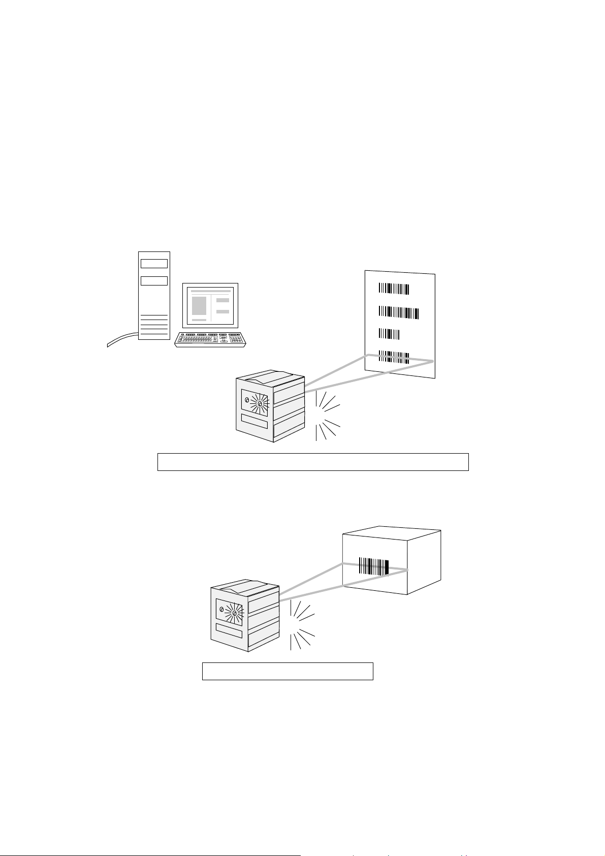
Beeps and LEDs
Using EasySet System software or reading configuration bar codes
green indicator
LED flashes
<beep> <beep> = GOOD READ
<beep> <beep> <beep> <beep> <beep> <beep> = SETUP ERROR
Reading "normal" bar codes
green indicator
LED flashes
no beep = NO READ / NO TRANSMISSION
<beep> = GOOD READ
MS/3300/IG/10/E/9708314-2
Page 23

5 Setting up your MaxiScan 3300
Modifying your setup parameters
The MaxiScan 3300 is pre-programmed with a set of factory default
parameter settings, but you may need to modify some of the settings
to suit your application.
You can use the EasySet System configuration software to download
your custom settings directly to the MaxiScan 3300 or print out the
corresponding configuration bar codes.
You can also use the host system to set up the MaxiScan 3300
dynamically according to your application.
Install and start up EasySet System
The minimum configuration for the EasySet System configuration software is
Windows™ 3.11 running on a 486 PC with 8 MB RAM.
1. Open the EasySet directory on your product cd-rom or diskette.
2. Double-click the setup.exe file to install the EasySet System
configuration software on your PC.
3. Double-click the EasySet icon from the Windows™ program
manager to start up EasySet.
MS/3300/IG/00/E/970630 5-1
Page 24
5. Setting up your MaxiScan 3300
Step-by-step mode
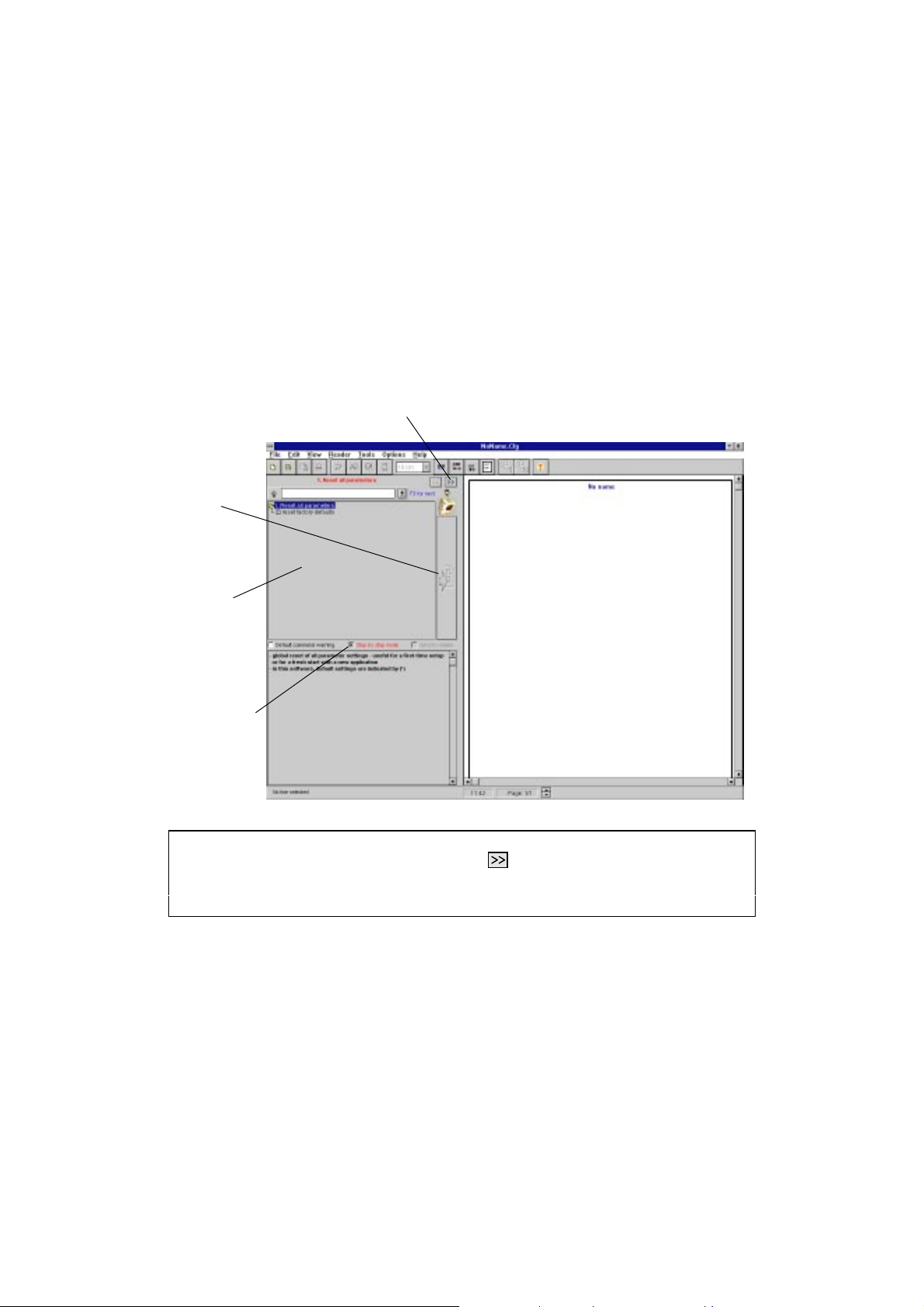
EasySet starts up in Step-by-step mode—the Step-by-step mode
checkbox is selected and the commands window shows the command
for the first step.
next-step button
vertical command
button
commands
window
Step-by-step mode
checkbox
Step-by-step mode ensures that new users do not miss any steps during setup. When you
have completed a step, click the next-step button to go on to the next step.
Experienced users can deselect the Step-by-step mode checkbox for direct access to all
the setup commands.
MS/3300/IG/00/E/9706305-2
Page 25
5. Setting up your MaxiScan 3300
Using the commands window
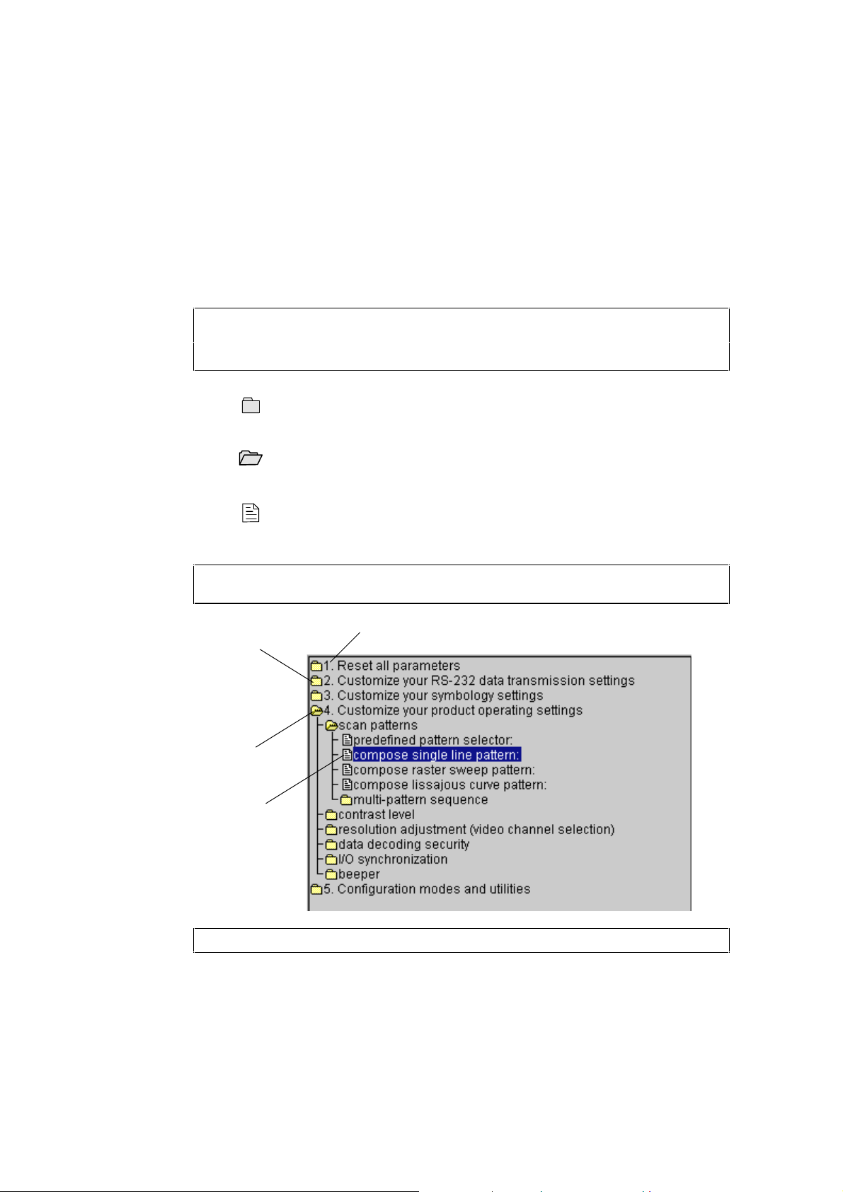
The setup commands in the commands window are presented in numbered sections
corresponding to the different steps in a setup session.
Each section is organized as a tree structure and uses the following symbols:
a closed branch with more information underneath—double-click on the
corresponding line to open the branch and see more
an open branch—double-click on the corresponding line to close the branch
and all the branches underneath
a setup command—double-click on the corresponding line to send the
command to the setup sheet (and to the MaxiScan 3300 if you have chosen
online setup)
You can also use the vertical command button to send commands to the setup sheet and to
the MaxiScan 3300—click once on the button (single click).
numbered sections
closed branch
open branch
setup command
All the sections are visible in this example (Step-by-step mode has been deactivated).
MS/3300/IG/00/E/970630 5-3
Page 26
5. Setting up your MaxiScan 3300
Select the MaxiScan 3300
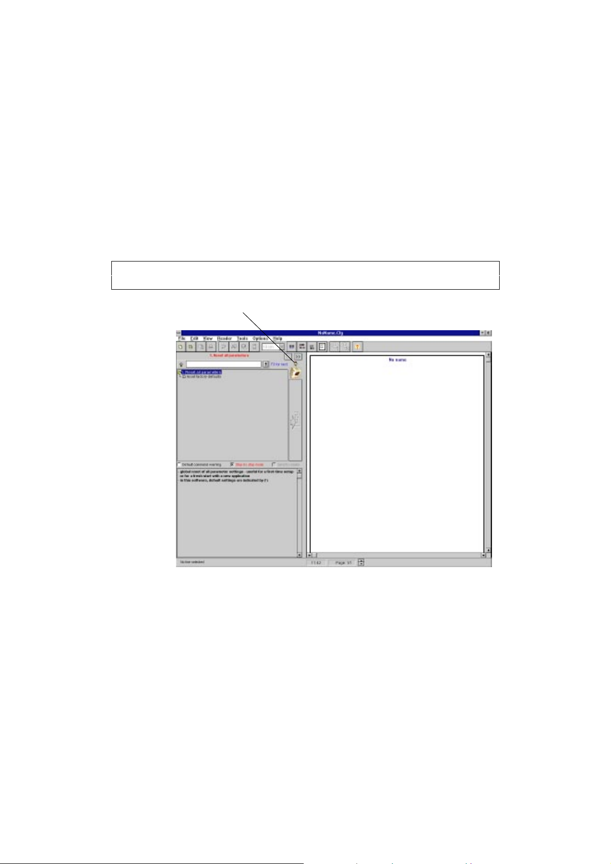
♦ Choose MaxiScan 3300 with the Reader - Select command if the
MaxiScan 3300 is not already selected.
You can also use the Change reader icon at the top of the vertical command button to
select the MaxiScan 3300.
Change reader icon
MS/3300/IG/00/E/9706305-4
Page 27
5. Setting up your MaxiScan 3300
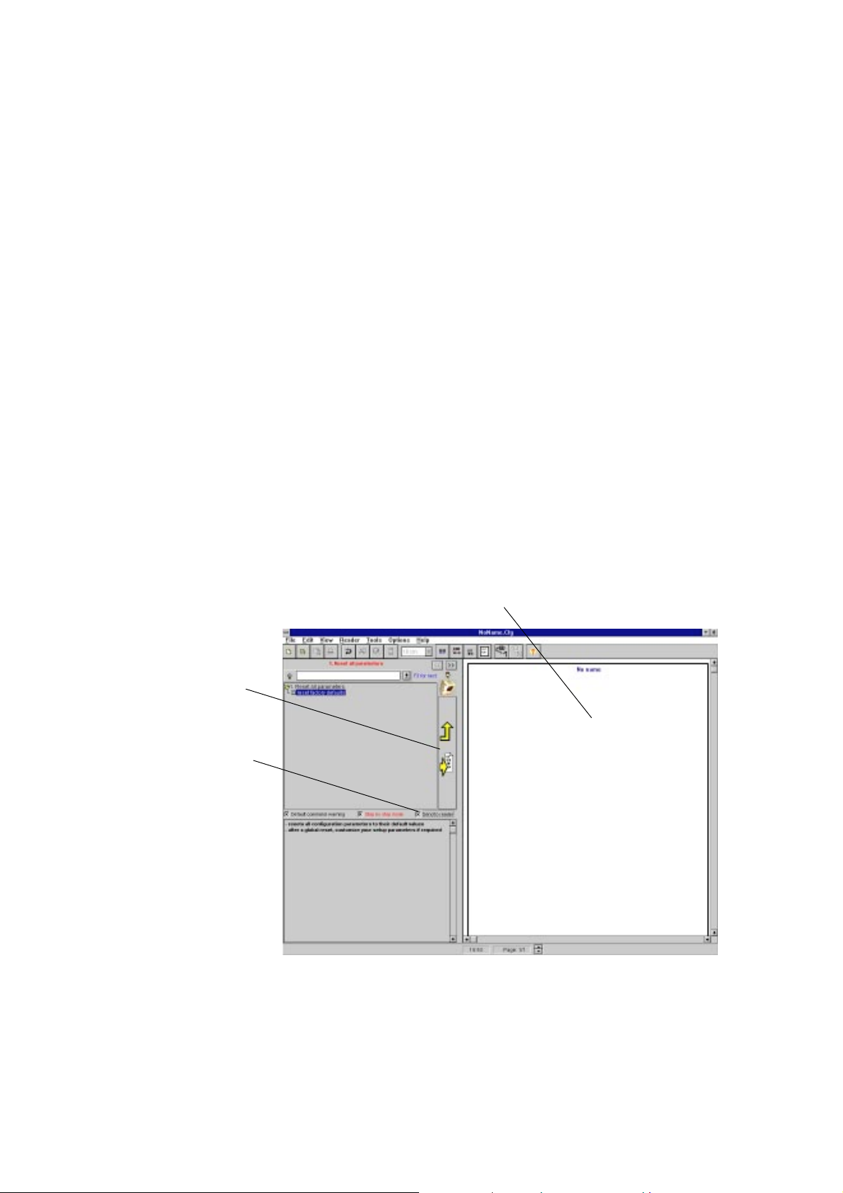
If you want to work online with the MaxiScan 3300
1. Connect the standard RS-232 C cable between the HOST port of the
MaxiScan Connexion System and the serial port of your PC if it is not
already connected.
2. Choose Reader - Configure communication PC/Reader and select
the Port the MaxiScan 3300 is connected to.
3. Click SelfSet.
The software adapts the RS-232 communication parameters of your
PC to the current settings of the MaxiScan 3300.
4. Select the Send to reader checkbox under the commands window if
you want to send commands directly to the MaxiScan 3300 as well as
to the setup sheet.
The download arrow is displayed on the vertical command button.
setup sheet
vertical command
button
Send to reader
checkbox
MS/3300/IG/10/E/970831 5-5
Page 28
5. Setting up your MaxiScan 3300
Make a new setup for your MaxiScan 3300
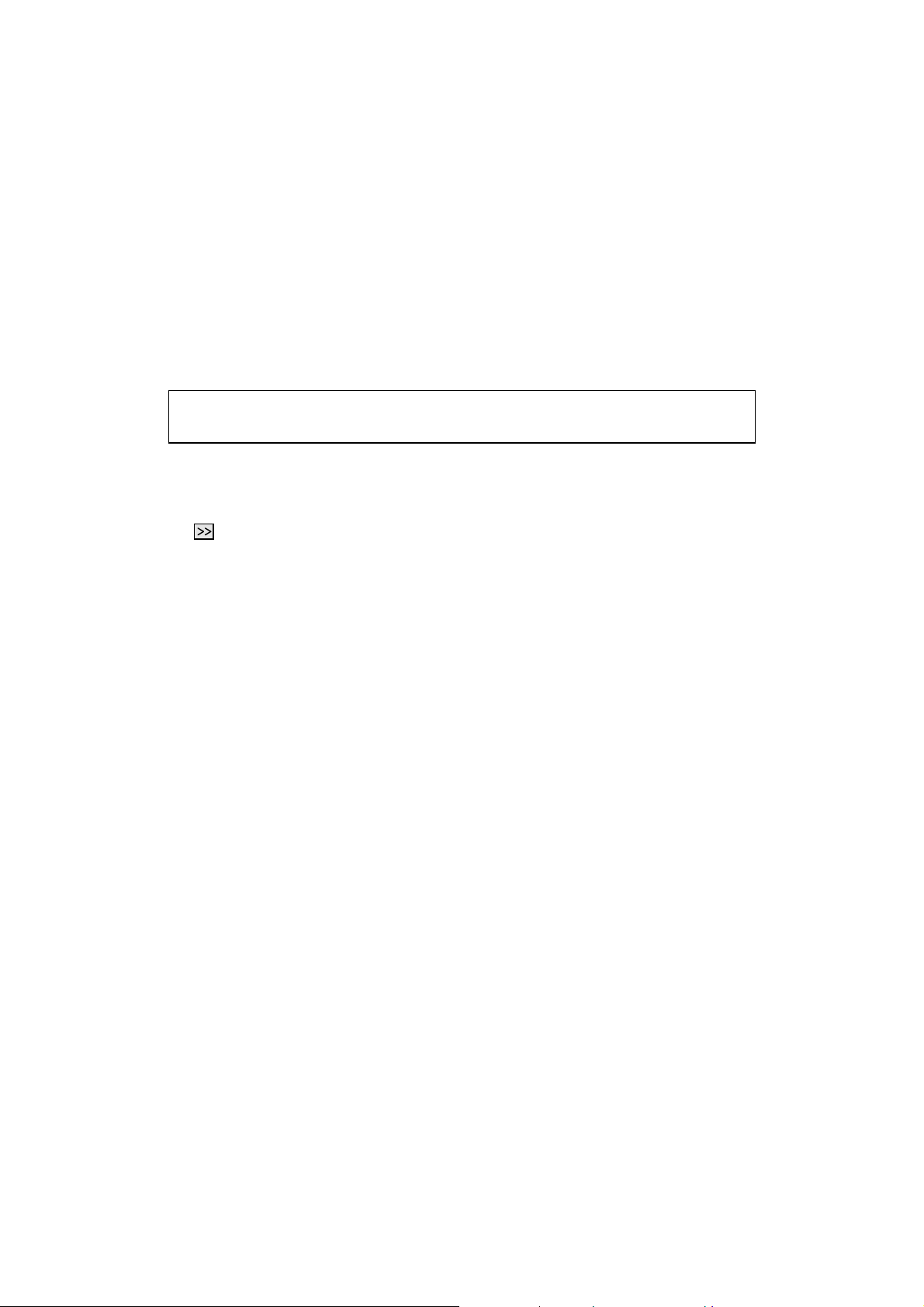
1. Reset all parameters
Selecting reset factory defaults makes sure that you start with a "clean" setup.
Factory default settings are indicated by an asterisk (*) in the software.
1. Select reset factory defaults and double-click to send it to the setup
sheet.
2. Click the next-step button to go on to the next step.
MS/3300/IG/10/E/9708315-6
Page 29

5. Setting up your MaxiScan 3300
2. Customize your RS-232 data transmission settings
1. Look at the data transmission settings the MaxiScan 3300 needs for
communication with your application host system.
2. Select the settings you need if they are not already selected by
default—double-click the selected commands or click the vertical
command button.
3. Click the next-step button to go on to the next step.
MS/3300/IG/10/E/970831 5-7
Page 30
5. Setting up your MaxiScan 3300
3. Customize your symbology settings
Code 39 and UPC/EAN are activated by default.
Do not activate symbologies that you do not need.
1. Deactivate the Code 39 and UPC/EAN default symbologies if you do
not need them.
2. Activate the symbologies you need if they are not already activated by
default.
3. Look at the settings for your symbologies.
4. Select the settings you need if they are not already selected by
default—double-click the selected commands or click the vertical
command button.
If the bar codes in your application have fixed lengths, the compose 1 or 2 or 3 fixed
lengths option gives the best reading efficiency and security.
If not, use the compose minimum length option—select the same length as the minimum
length in your application (do not select a shorter length !!).
Use check digits if available to increase data security.
5. Click the next-step button to go on to the next step.
MS/3300/IG/10/E/9708315-8
Page 31
5. Setting up your MaxiScan 3300
4. Customize your product operating settings
1. Select the settings you need if they are not already selected by
default—double-click the selected commands or click the vertical
command button.
Choosing the right operating settings is very important for optimized reading
performance ! This is especially true for the following parameters.
scan patterns
• single line • picket fence and ladder reading
• set scan rate / position (scan width depends on reading
distance)
• picket fence—increase scan width to increase the number
of scans
• ladder—limit scan width to just over width of code if
possible to avoid wasted scans
• raster
• lissajous curves • undefined orientation
• multipattern sequence • for variable orientation and position
• scan rate • increase the scan rate if your application uses small bar
MS/3300/IG/10/E/970831 5-9
• picket fence only—do not use for ladder reading !
• good for poor quality or damaged labels (read same code
at different heights) or variable label position
• useful for multicode applications
• set scan rate / sweep angle (scan area depends on reading
distance and sweep angle)
• limit raster or pattern to height of code if possible to avoid
wasted scans
• more directions = lower effective scan rate per line
• suitable for static reading or slow pass-through applications
• cross pattern provides good coverage with codes that are
higher than wide
codes and higher pass-through speeds
Page 32
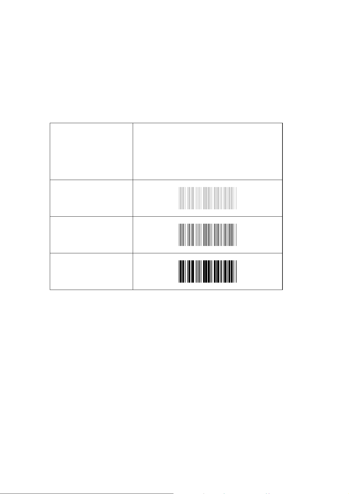
5. Setting up your MaxiScan 3300
contrast level
• all contrast levels • cycles through all contrast levels for labels with varying
contrast
• OK when presenting labels, not good for passthrough
applications
• reading is slower than with dedicated contrast levels—
use dedicated contrast levels (low, medium, high) if
possible
• low contrast
• medium contrast
• high contrast
MS/3300/IG/10/E/9708315-10
Page 33
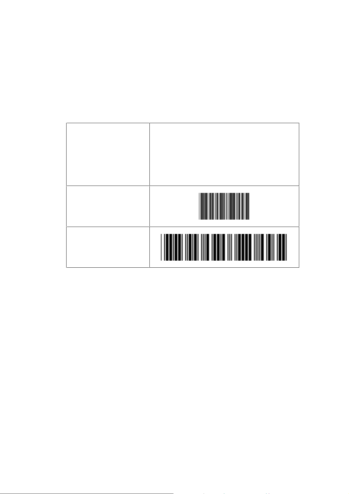
5. Setting up your MaxiScan 3300
resolution adjustment (video channel selection)
• high / low resolution • continuous switching between the 2 video channels—the
video channel changes with each new scan
• normal-quality medium-resolution bar codes such as
standard EAN (100%) are read easily by both video
channels
• reading is slower than with dedicated resolution
levels—use dedicated resolution levels (high, low) if
possible
• high resolution
• low resolution
MS/3300/IG/10/E/970831 5-11
Page 34
5. Setting up your MaxiScan 3300
data decoding security
• timeout between identical
consecutive codes
• timeout between different
consecutive codes
2. Click the next-step button to go on to the next step.
• prevents reading the same bar code more than once
• prevents unwanted reading of other bar codes on the same
label
• longer timeout = slower reading of different codes
MS/3300/IG/10/E/9708315-12
Page 35

5. Setting up your MaxiScan 3300
5. Configuration modes and utilities
The configuration inhibit after 1 minute option protects against
unwanted reading of configuration codes and greatly improves
reading performance for the "normal" bar codes in your application.
If you use a setup sheet for configuration and the configuration
inhibit after 1 minute option is selected, you must disconnect and
then reconnect the MaxiScan 3300 power supply to enable reading of
configuration codes.
You then have 1 minute to read a setup code (if you do not read a
code within 1 minute, the MaxiScan 3300 will leave configuration
mode and you will have to switch off and restart the MaxiScan 3300
again). Every new configuration code you read enables the MaxiScan
3300 to read another configuration code within 1 minute.
You have now created a setup for your MaxiScan 3300.
Choose File - Save as if you want to save your setup sheet (the filename you give must
have the extension .cfg).
MS/3300/IG/10/E/970831 5-13
Page 36
5. Setting up your MaxiScan 3300
Editing and printing out the setup sheet
You may want to use the setup sheet for a number of reasons:
• you did not choose to download the setup commands directly to the MaxiScan 3300,
• you want to use the same setup for other MaxiScan 3300 units installed on your site,
• you want to keep a record on paper of your setup.
If the "configuration inhibit after 1 minute" option is selected, you must disconnect
and then reconnect the MaxiScan 3300 power supply to enable reading of the
configuration codes on the setup sheet (repeated 1-minute cycle).
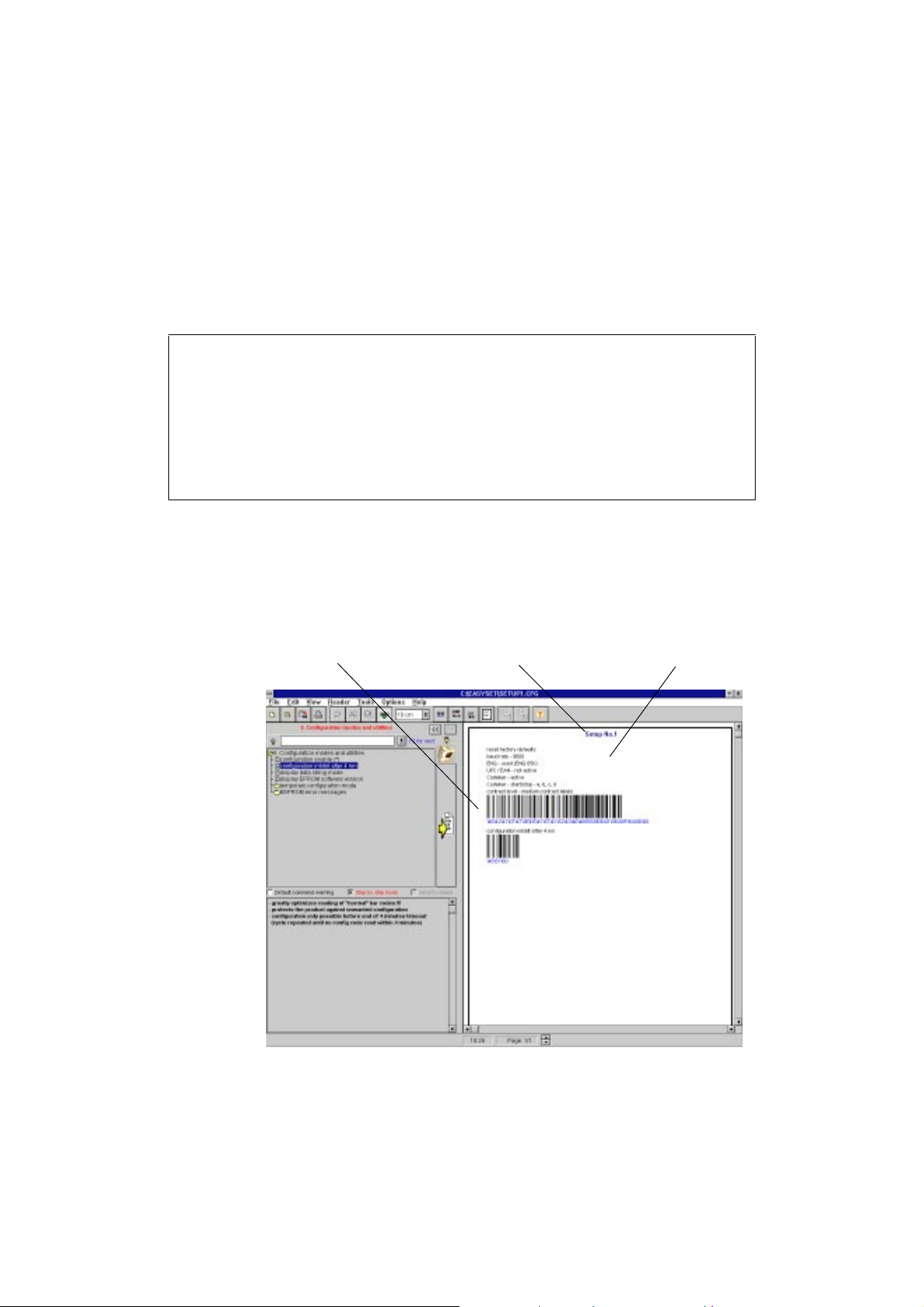
1. Choose Edit - Concatenate if you want to reduce the number of
codes you have to read with the MaxiScan 3300.
2. Choose Edit - Title if you want to give a title to your setup sheet.
3. Choose File - Print if you want to print out your setup sheet.
concatenated configuration codes
setup sheettitle
MS/3300/IG/10/E/9708315-14
Page 37
5. Setting up your MaxiScan 3300
Sending commands from the setup sheet
1. Connect the standard RS-232 C cable between the HOST port of the
MaxiScan Connexion System and the serial port of your PC if it is not
already connected.
2. Choose Reader - Configure communication PC/Reader and select
the Port the MaxiScan 3300 is connected to.
3. Click SelfSet.
The software adapts the RS-232 communication parameters of your
PC to the current settings of the MaxiScan 3300.
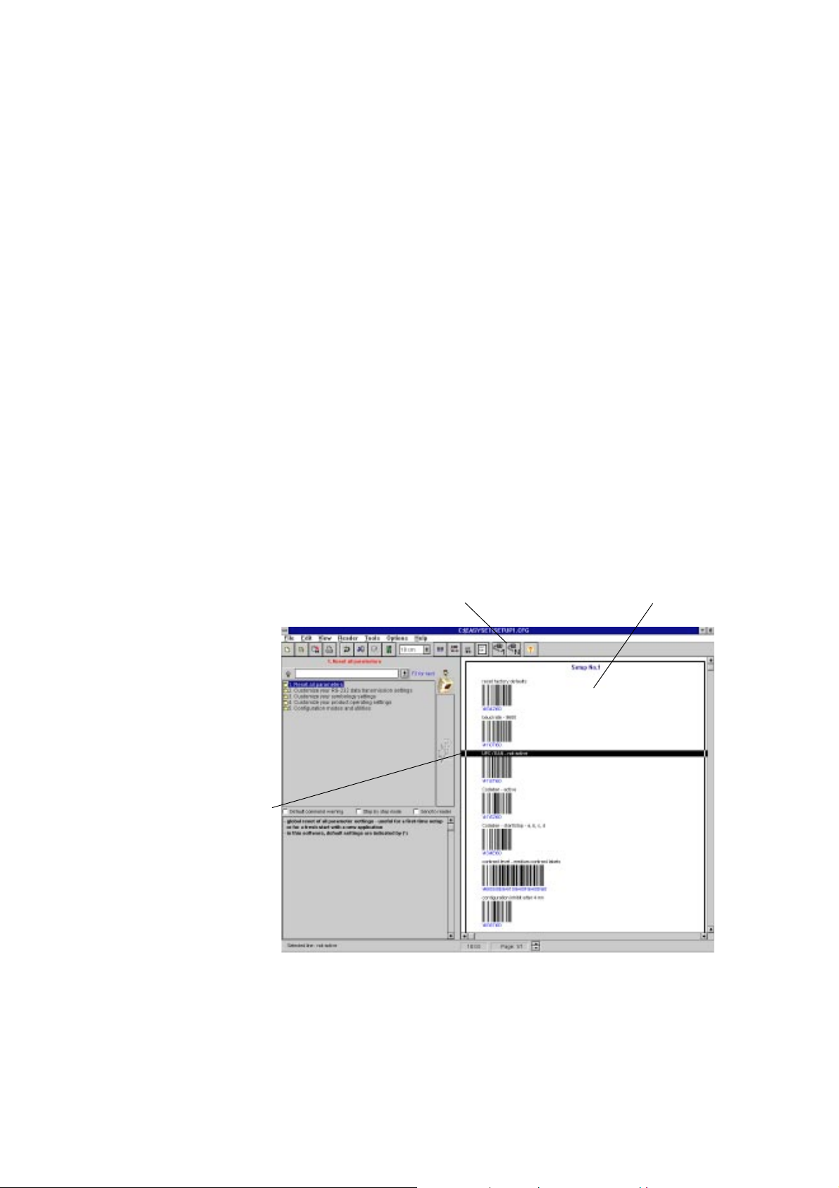
4. Select a command title in the setup sheet and click the Send selected
command icon to send the command to the MaxiScan 3300.
The Send all commands icon sends all the commands in the setup
sheet to the MaxiScan 3300.
Send selected command / Send all commands icons setup sheet
selected command
MS/3300/IG/10/E/970831 5-15
Page 38

5. Setting up your MaxiScan 3300
MS/3300/IG/10/E/9708315-16
Page 39
A Technical characteristics
Technical characteristics are subject to change without prior notice due to continuous
product improvement.
Models
MaxiScan 3300 ST standard model
MaxiScan 3300 HR high resolution
option laser diode thermocooler—required if ambient temperature
accessories
Interface capability
host system interfaces
I/O synchronization
Decoding capability
symbologies
above 27°C (80°F)
• MaxiScan Connexion System connection unit
• mains power supply adapter
(15 VDC, 0.65 A, 10 Watt full-wave rectified unregulated)
• adjustable stand
• RS-232 C (standard configuration)
• RS-422
• RS-485
• Current Loop (passive type)–requires MCS connection unit
• input sync from external device (opto-switch, . . .)
• output sync to external device (conveyor gate switch, . . .)
• software output to host system
• Codabar
• Codablock
• Code 39
• Code 93
• Code 128
• EAN 128
• Industrial / Standard 2 of 5
• Interleaved 2 of 5
• Matrix 2 of 5
MS/3300/IG/10/E/970831 A-1
Page 40
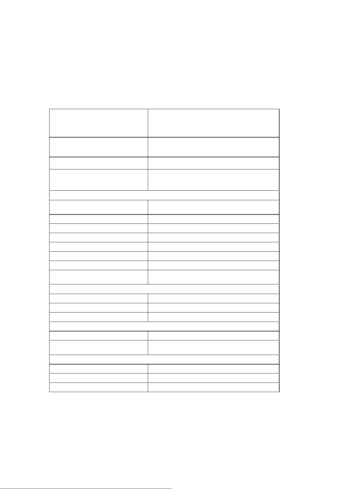
A. Technical characteristics
• MSI Code
• Plessey Code
• UPC/EAN
• others on request
code reconstruction
decoding rate
other decoding features
Scanning performance
scan rate
maximum scan angle (scan width) 45° ± 4°
maximum sweep angle (raster height) adjustable increments to 30° ± 4°
reading distance / depth of field see charts in next section
pitch ± 70°
skew ± 40°
minimum print contrast ratio 25 %
minimum resolution
Optical characteristics
light source 5 mW long-life red laser diode
wavelength 660 nm
laser class US CDRH Class II, IEC Class 2
Electrical characteristics
power supply voltage 7-25 VDC full-wave rectified unregulated
power requirements
Physical characteristics
dimensions (width x depth x height) 82 x 75 x 100 mm (3.2 x 2.9 x 3.9")
maximum weight without cord 550 g (19.4 oz)
case Epoxy-coated aluminium
• optional for EAN-13, UPC-A
• automatic with 1 fixed length selected for Code 39,
CIP 128, Codabar CLSI, MSI Code, Plessey Code
real-time with scanning rate if only 1 or 2 symbologies are
selected
• multicode reading
• code sorting
• autodiscrimination of symbologies
• 400 to 700 scans/second
• 450 scans/second at 40° scan angle (default)
• ST: 0.19 mm (7 mil)
• HR: 0.08 mm (3 mil)
• < 3.5 Watt normal operation (higher peaks at power-up)
• < 4.75 Watt with thermo-cooler (higher peaks at power-up)
MS/3300/IG/10/E/970831A-2
Page 41
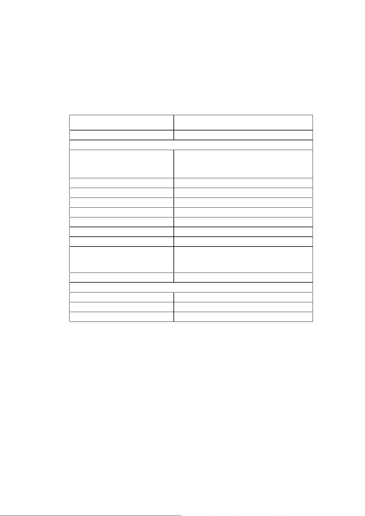
A. Technical characteristics
mounting
connector 15-pin subD
Environmental characteristics
operating temperature
storage temperature -40° to 70° C (-40° to 158° F)
sealing standards (dust, corrosive chemicals) IP65 / Nema 12
relative humidity 5% to 95% non-condensing
maximum ambient lighting 4 000 lux on the code
electrostatic discharge 8 kV to any external surface
vibration IEC 6826 - Fc
shock IEC 68227 - Ea
CE standards conformity
MTBF 20 000 hours according to operating conditions
User interface
power-up red LED - 2 beeps
good read 1 green LED flash - 1 beep
configuration error 6 error beeps
• metric screw threads under case
• can be mounted in any position
• 0° to 50° C (32° to 122° F)
• use thermo-cooler for temperatures > 27° C
• use thermo-cooler and input sync device for temperatures
> 40° C
• Emission: EN 50081-2 (1995), EN 55022 (1987) Class A
• Immunity: EN 50082-2 (1995)
• Safety: EN 60950 (1993) / IEC 950
MS/3300/IG/10/E/970831 A-3
Page 42
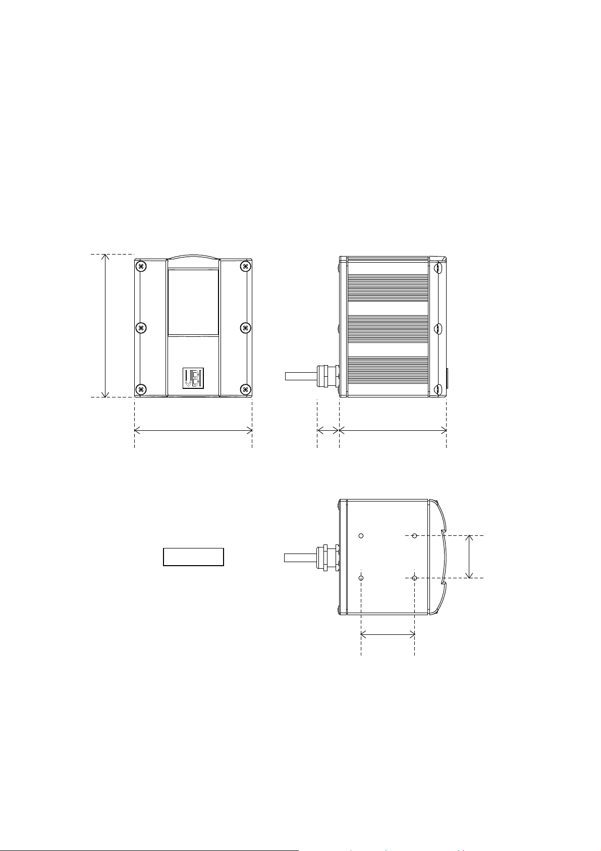
A. Technical characteristics
Dimensions
MaxiScan 3300
100 mm
(3.9")
82 mm (3.2")
Scale: ½
75 mm (2.9")
14 mm
(0.5")
30 mm
(1.2")
38 mm (1.5")
MS/3300/IG/10/E/970831A-4
Page 43
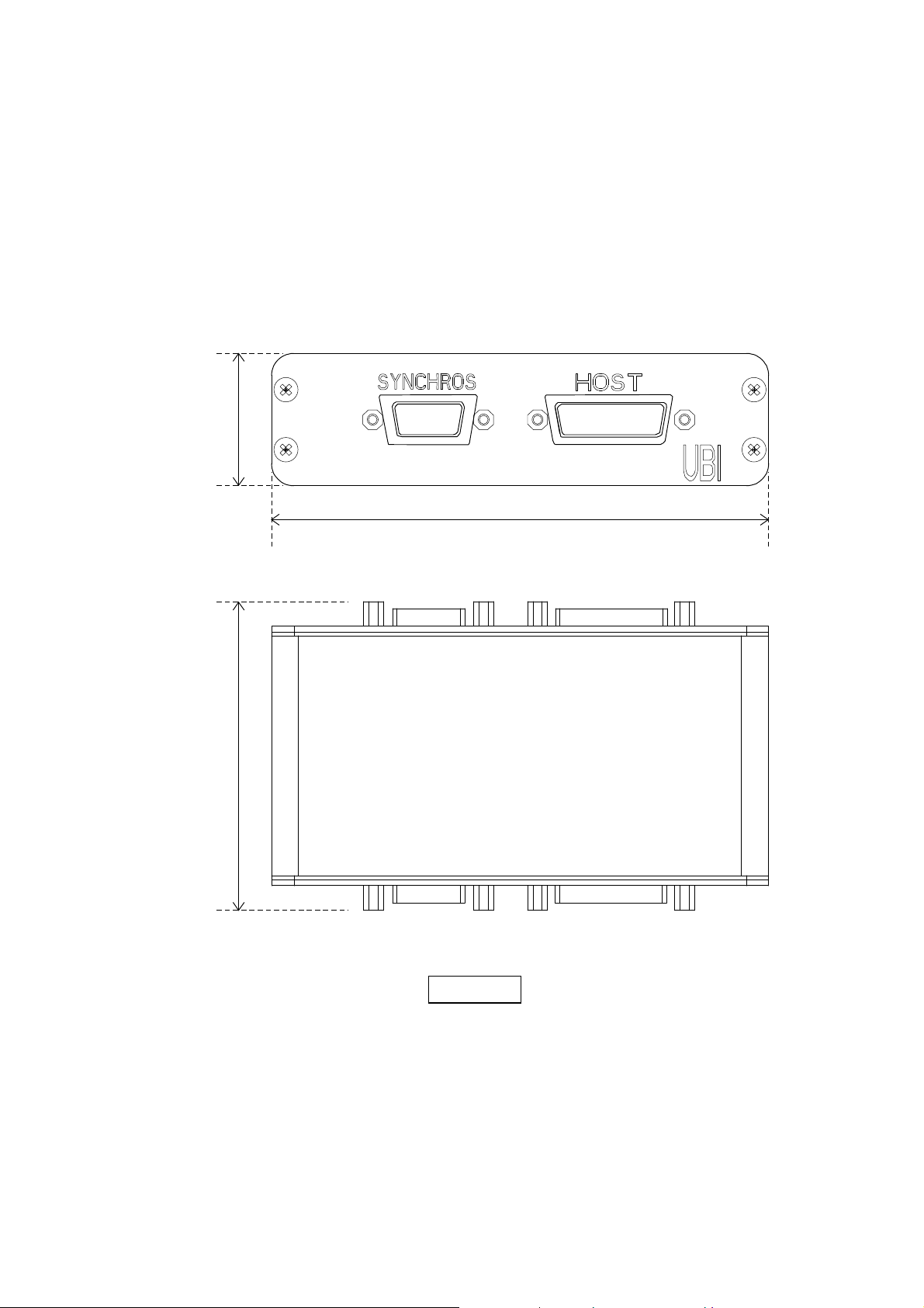
Maxiscan Connexion System (external unit)
30 mm
(1.18")
113 mm (4.45")
A. Technical characteristics
70 mm
(2.76")
Scale: 1
MS/3300/IG/10/E/970831 A-5
Page 44
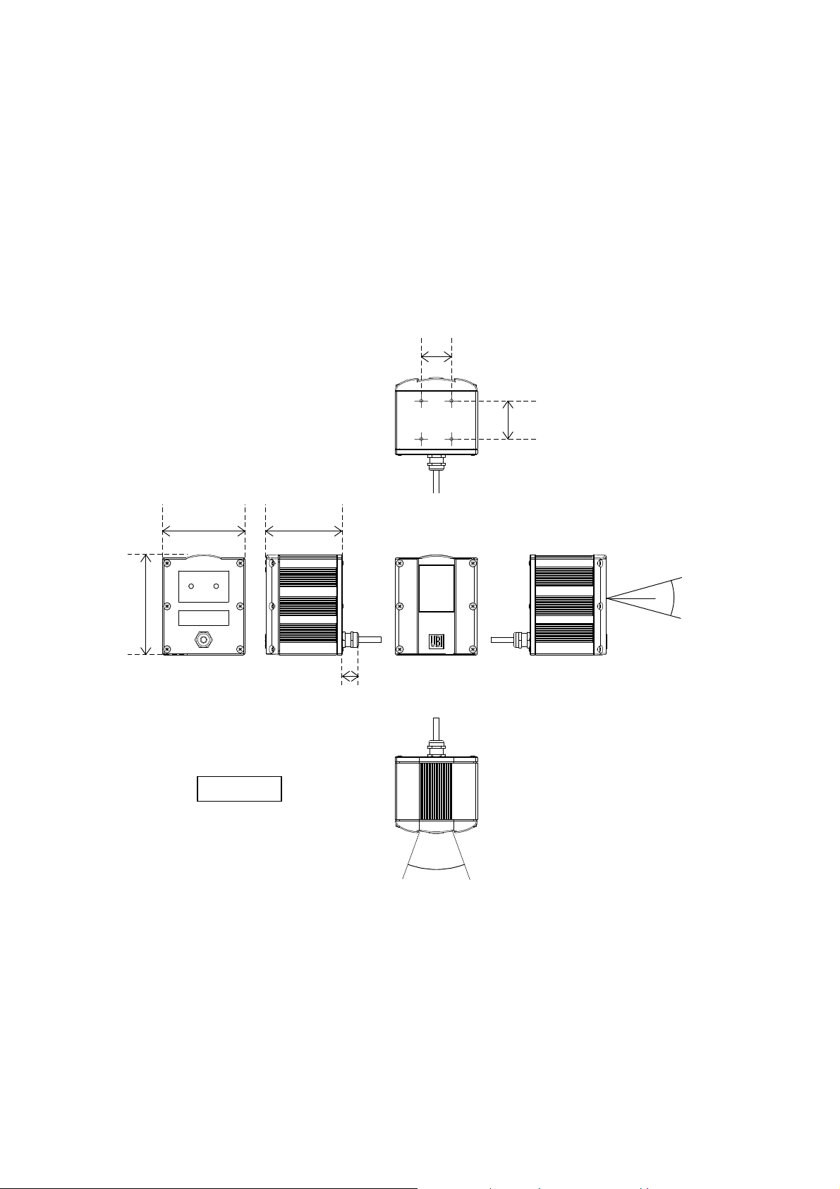
A. Technical characteristics
Mounting points / laser light plane
30 mm
(1.2")
38 mm (1.5")
100 mm
(3.9")
82 mm (3.2")
Scale: ¼
75 mm (2.9")
30°
14 mm
(0.5")
40°
MS/3300/IG/10/E/970831A-6
Page 45
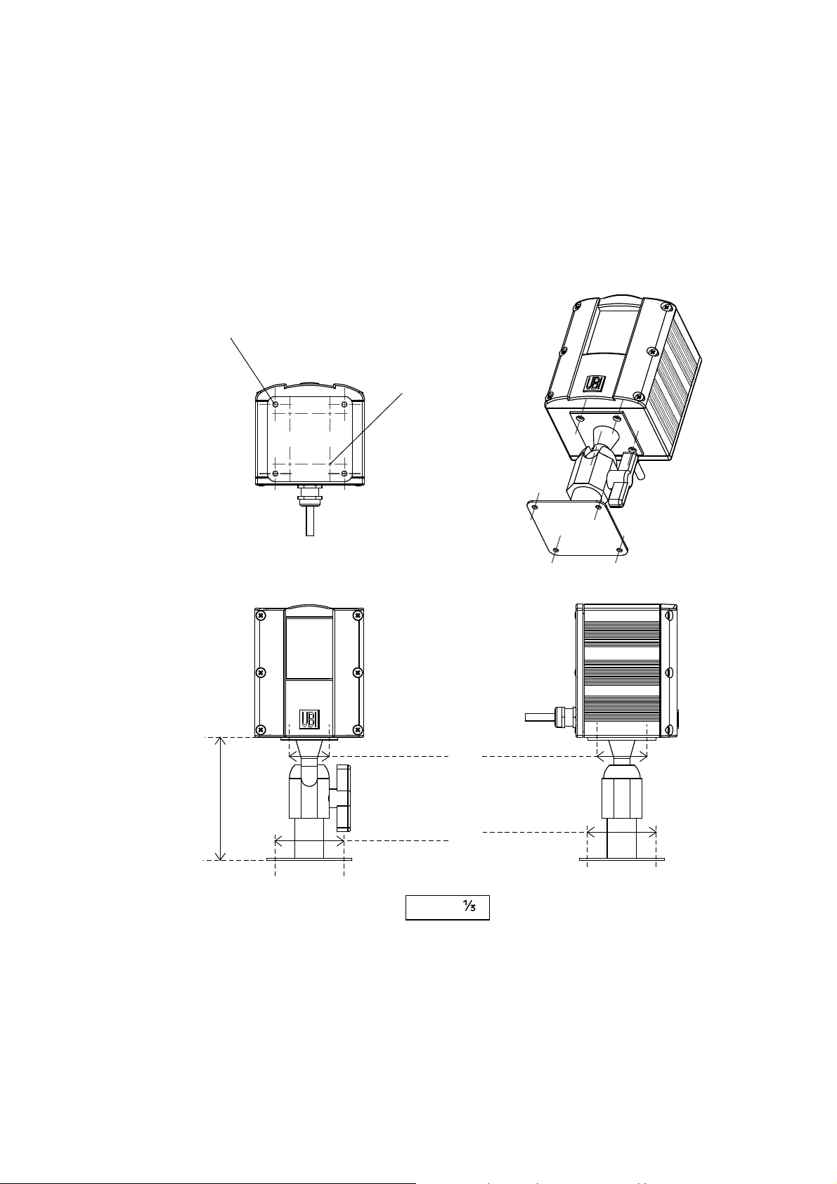
Optional adjustable stand
4 x Ø 4
A. Technical characteristics
4 x M 4
5 mm (0.2") depth
30 mm (1.18")
92.5 mm
(3.64")
52 mm (2.01")
38 mm (1.5")
52 mm (2.01")
Scale:
MS/3300/IG/10/E/970831 A-7
Page 46
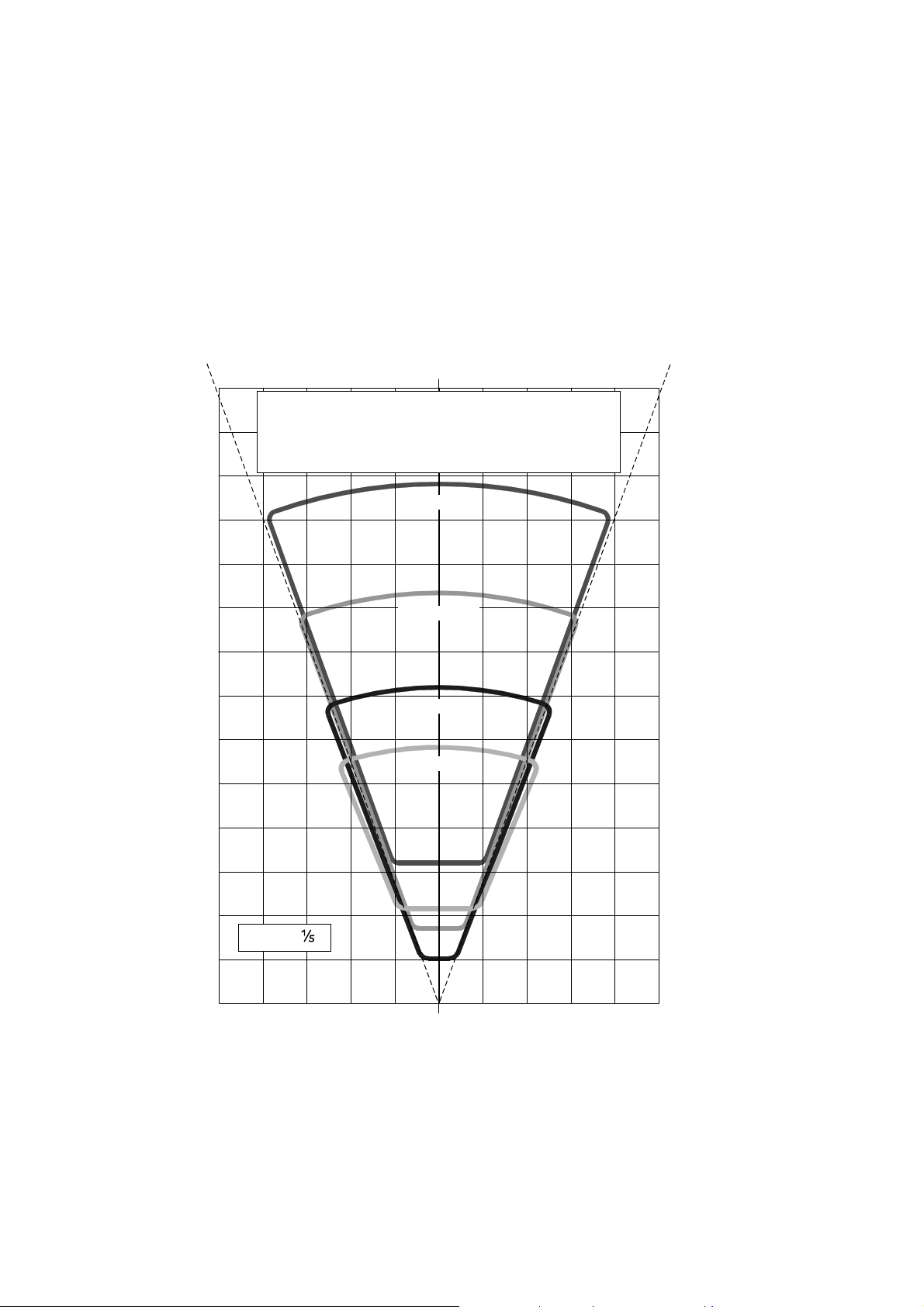
A. Technical characteristics
0.3 mm (12 mil)
0.2 mm (8 mil)
0.5 mm (20 mil)
1.0 mm (40 mil)
Horizontal scan width / reading distance / barcode density
MaxiScan 3300 ST
9.8" 7.9" 5.9" 3.9" 2" 0" 2" 3.9" 5.9" 7.9" 9.8"
700
650
600
The chart shows the horizontal reading range (top view) of the
MaxiScan 3300 ST.
The values shown are for high-contrast Code 39 with a ratio of 1:3
and correspond to the product default settings—increased
performance is possible with specific configuration setups.
27.6"
25.6"
23.6"
550
500
450
400
350
300
250
200
150
100
50
21.7"
19.7"
17.7"
15.7"
13.8"
11.8"
9.8"
7.9"
5.9"
3.9"
Scale:
2"
0
mm
250 200 150 100 50 0 50 100 150 200 250
MS/3300/IG/10/E/970831A-8
0"
Page 47
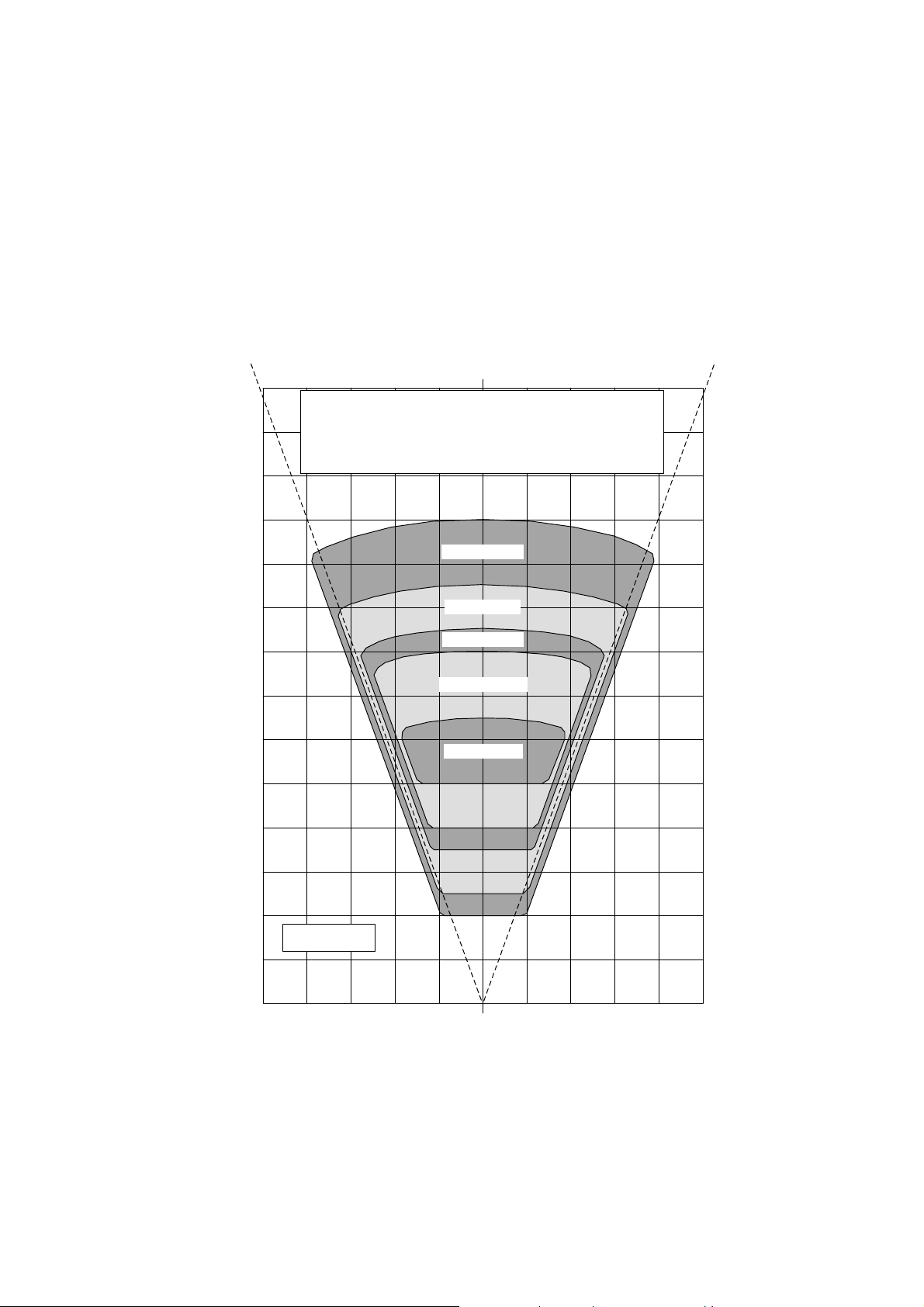
A. Technical characteristics
0.3 mm (12 mil)
0.2 mm (8 mil)
0.15 mm (6 mil)
0.125 mm (5 mil)
0.1 mm (4 mil)
Horizontal scan width / reading distance / barcode density
MaxiScan 3300 HR
3.9" 3.1" 2.4" 1.6" 0.8" 0" 0.8" 1.6" 2.4" 3.1" 3.9"
280
260
240
The chart shows the horizontal reading range (top view) of the
MaxiScan 3300 HR for high density codes.
The values shown are for high-contrast Code 39 with a ratio of 1:3
and correspond to the product default settings—increased
performance is possible with specific configuration setups.
11.0"
10.2"
9.4"
220
200
180
160
140
120
100
80
60
40
20
8.7"
7.9"
7.1"
6.3"
5.5"
4.7"
3.9"
3.1"
2.4"
1.6"
Scale: ½
0.8"
0
mm
100 80 60 40 20 0 20 40 60 80 100
0"
MS/3300/IG/10/E/970831 A-9
Page 48

A. Technical characteristics
MS/3300/IG/10/E/970831A-10
Page 49
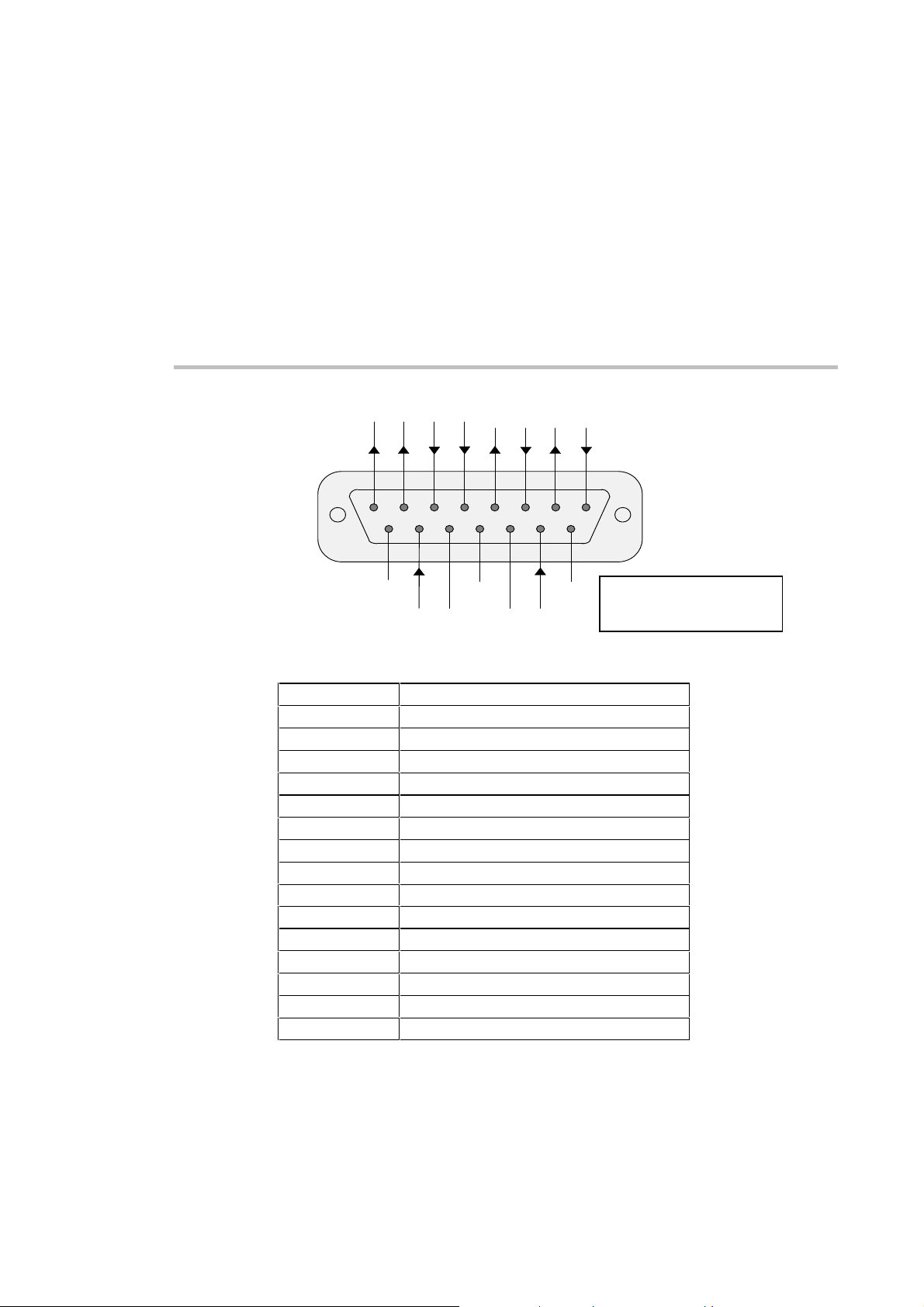
B MaxiScan 3300 cable connector
SO- SO+ SI- SI+
8 7 6 5 4 3 2 1
15 14 13 12 1 1 10 9
NC SHIELD NC
7-25 GND GND 7 -2 5
VDC VDC
RTS C T S TX RX
TX+ RX+ TX- R X-
RS-232 C
RS-422 / 485
both 7-25 VDC power supply
pins must be powered
both GND pins must be used
15-pin subD female connector
pin function
1 receive data (RS-232 C) / RX- (RS-422 / 485)
2 transmit data (RS-232 C) / TX- (RS-422 / 485)
3 clear to send (RS-232 C) / RX+ (RS-422 / 485)
4 request to send (RS-232 C) / TX+ (RS-422 / 485)
5 positive synchronization input (SI+)
6 negative synchronization input (SI-)
7 positive synchronization output (SO+)
8 negative synchronization output (SO-)
9 not connected
10 power in (7 to 25 VDC 10 Watt unregulated)
11 power ground
12 shield
13 power ground
14 power in (7 to 25 VDC 10 Watt unregulated)
15 not connected
MS/3300/IG/10/E/970831 B-1
Page 50
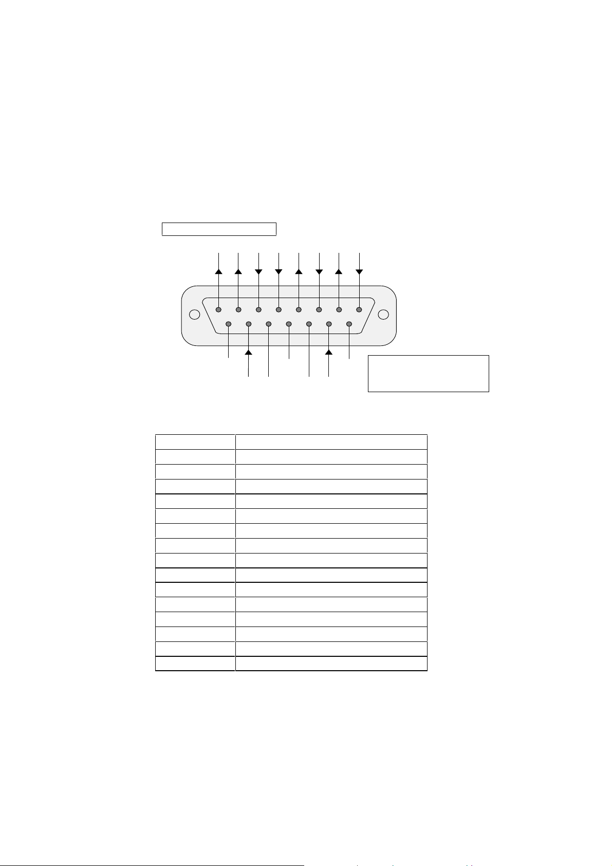
B. MaxiScan 3300 cable connector
RS-232 C
I/O sync max current 50 mA
SO- SO+ SI- SI+ RTS CT S TX RX
8 7 6 5 4 3 2 1
15 14 13 12 1 1 10 9
NC SHIELD NC
7-25 GND GND 7 -2 5
VDC VDC
both 7-25 VDC power supply
pins must be powered
both GND pins must be used
15-pin subD female connector
pin function
1 receive data (RS-232 C)
2 transmit data (RS-232 C)
3 clear to send (RS-232 C)
4 request to send (RS-232 C)
5 positive synchronization input (SI+)
6 negative synchronization input (SI-)
7 positive synchronization output (SO+)
8 negative synchronization output (SO-)
9 not connected
10 power in (7 to 25 VDC 10 Watt unregulated)
11 power ground
12 shield
13 power ground
14 power in (7 to 25 VDC 10 Watt unregulated)
15 not connected
MS/3300/IG/10/E/970831B-2
Page 51
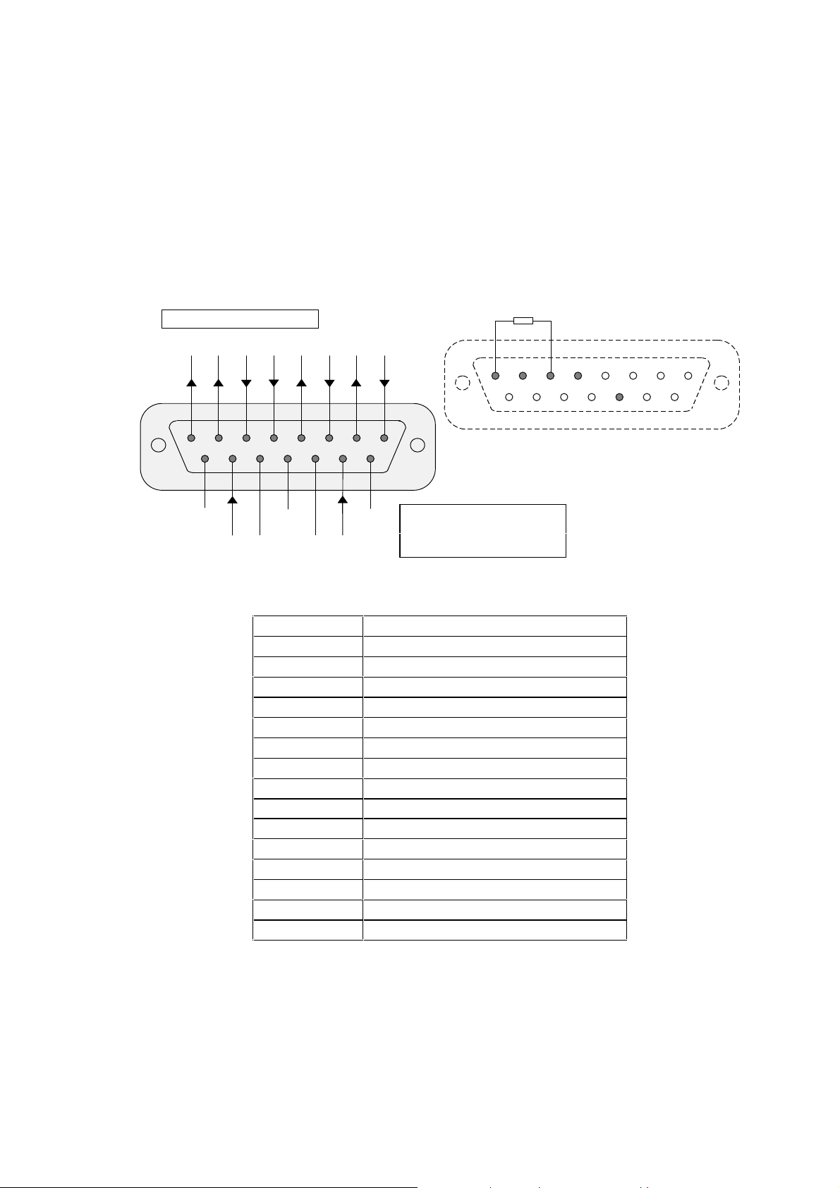
RS-422
I/O sync max current 50 mA
SO- SO+ SI- SI+ TX+ RX+ TX- RX-
8 7 6 5 4 3 2 1
15 14 13 12 11 10 9
B. MaxiScan 3300 cable connector
RS-422: install resistor = 100 Ohm
1 2 3 4 5 6 7 8
9 10 11 12 13 14 15
host male subD cable connector
NC SHIELD NC
7-25 GND GND 7-25
VDC VDC
both 7-25 VDC power supply
pins must be powered
both GND pins must be used
MaxiScan 3300 15-pin subD female connector
pin function
1 receive data RX- (RS-422)
2 transmit data TX- (RS-422)
3 receive data RX+ (RS-422)
4 transmit data TX+ (RS-422)
5 positive synchronization input (SI+)
6 negative synchronization input (SI-)
7 positive synchronization output (SO+)
8 negative synchronization output (SO-)
9 not connected
10 power in (7 to 25 VDC 10 Watt unregulated)
11 power ground
12 shield
13 power ground
14 power in (7 to 25 VDC 10 Watt unregulated)
15 not connected
MS/3300/IG/10/E/970831 B-3
Page 52
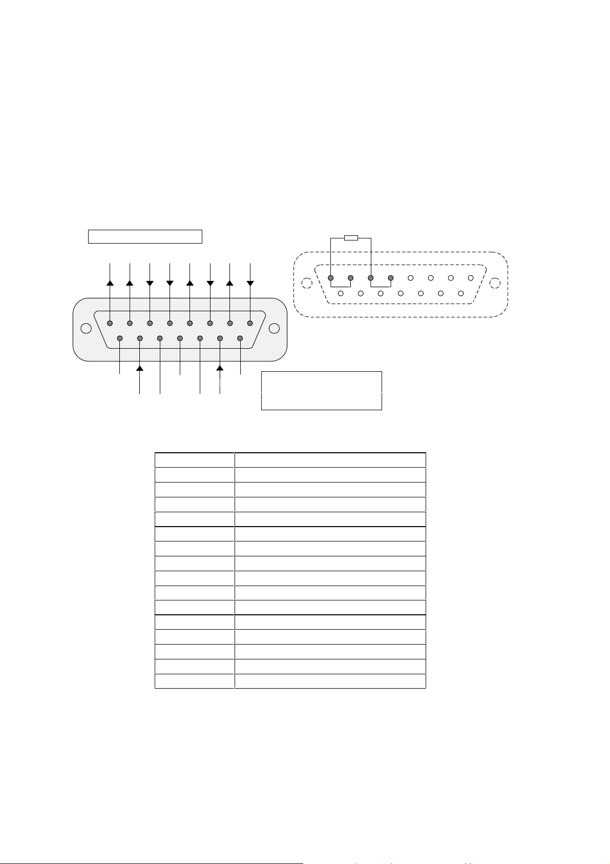
B. MaxiScan 3300 cable connector
RS-485
I/O sync max current 50 mA
SO- SO+ SI- SI+ TX+ RX+ TX- RX-
8 7 6 5 4 3 2 1
15 14 13 12 11 10 9
RS-485: connect pins 1 and 2 and c onnect pins 3 and 4
install resistor = 120 Ohm between pins 1 and 3
1 2 3 4 5 6 7 8
9 10 11 12 13 14 15
host male subD cable connector
NC SHIELD NC
7-25 GND GND 7-25
VDC VDC
both 7-25 VDC power supply
pins must be powered
both GND pins must be used
MaxiScan 3300 15-pin subD female connector
pin function
1 receive / transmit data RX- / TX- (RS-485)
2 receive / transmit data RX- / TX- (RS-485)
3 receive / transmit data RX+ / TX+ (RS-485)
4 receive / transmit data RX+ / TX+ (RS-485)
5 positive synchronization input (SI+)
6 negative synchronization input (SI-)
7 positive synchronization output (SO+)
8 negative synchronization output (SO-)
9 not connected
10 power in (7 to 25 VDC 10 Watt unregulated)
11 power ground
12 shield
13 power ground
14 power in (7 to 25 VDC 10 Watt unregulated)
15 not connected
MS/3300/IG/10/E/970831B-4
Page 53
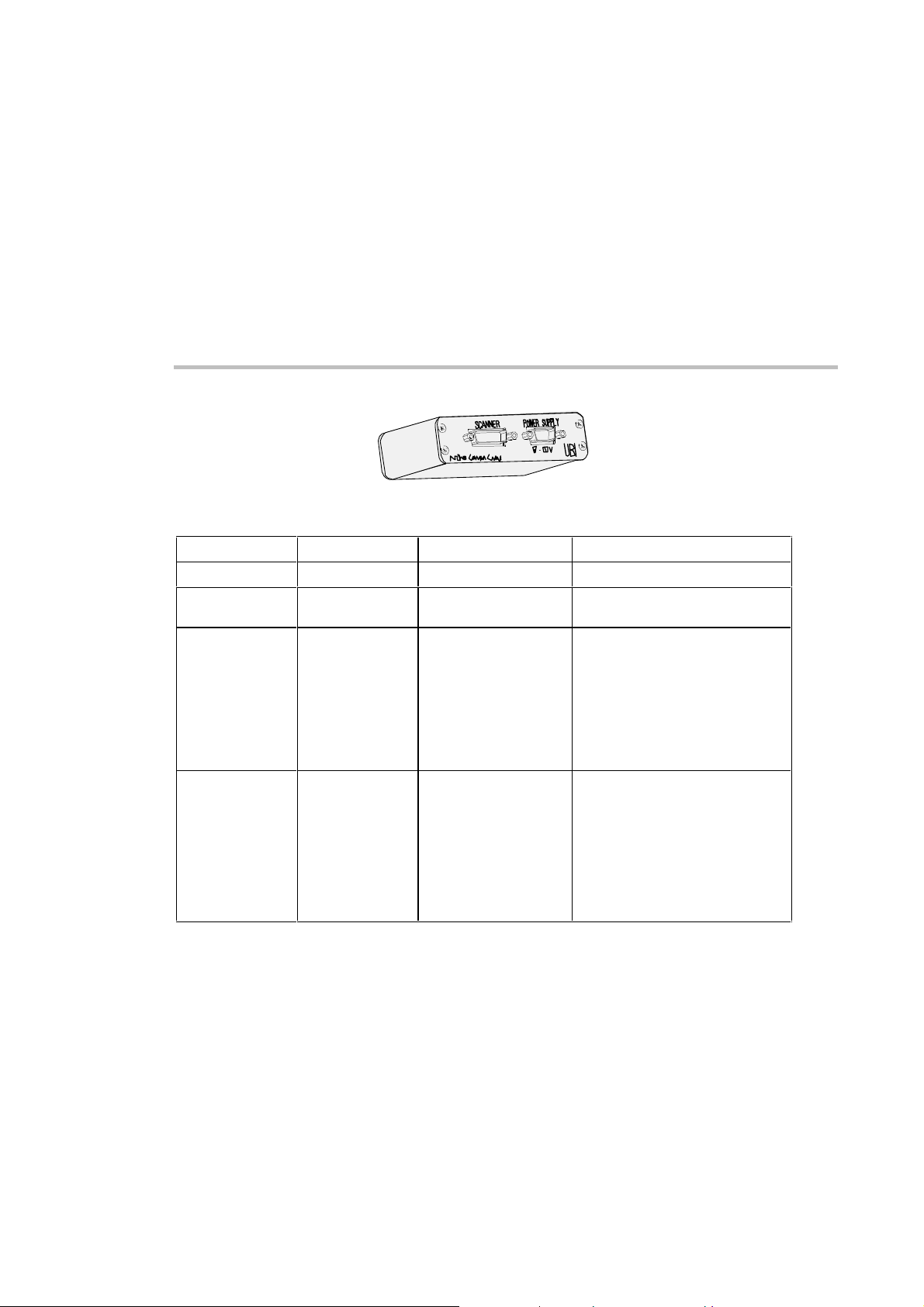
C MaxiScan Connexion System (MCS)
port type connection remarks
SCANNER
POWER SUPPLY
7-25 V
HOST
15-pin subD male MaxiScan 3300 9-pin subD male external power supply 7-25 V 10 Watt full-wave rectified
15-pin subD female host computer
unregulated power
• RS-232 C (standard configuration)
• RS-422
• RS-485
• Current Loop (requires MCS)
each host system interface is
software programmable and requires
a different cable
SYNCHROS
MS/3300/IG/10/E/970831 C-1
9-pin subD female I/O synchronization cable
• input synchronization—reading can
be triggered by an external cell,
automatic machine, electrical
control device
• output synchronization—an
external device (switch, alarm,
indicator light) can be triggered by
a good read or unsuccessful read
as required
Page 54
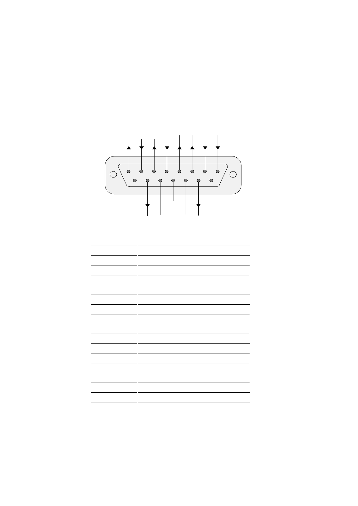
C. MaxiScan Connexion System (MCS)
SCANNER port
RS-232 C RX TX CTS RTS
RS-422 / 485 RX- TX- RX+ TX+
1 2 3 4 5 6 7 8
9 10 11 12 13 14 15
7-25 VDC PWR GND 7-25 VDC
SI+ SI- SO+ SO-
CHASSIS
GND
15-pin subD male connector
pin function
1 receive data (RS-232 C) / RX- (RS-422 / 485)
2 transmit data (RS-232 C) / TX- (RS-422 / 485)
3 clear to send (RS-232 C) / RX+ (RS-422 / 485)
4 request to send (RS-232 C) / TX+ (RS-422 / 485)
5 positive synchronization input (SI+)
6 negative synchronization input (SI-)
7 positive synchronization output (SO+)
8 negative synchronization output (SO-)
9 not connected
10 power in (7 to 25 VDC 10 Watt unregulated)
11 power ground
12 shield
13 power ground
14 power in (7 to 25 VDC 10 Watt unregulated))
15 not connected
MS/3300/IG/10/E/970831C-2
Page 55
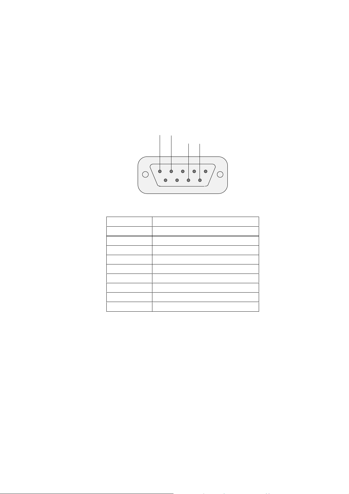
POWER SUPPLY 7-25V port
1 2 3 4 5
9-pin subD male connector
pin function
1 power in (7 to 25 VDC 10 Watt unregulated)
2 power in (7 to 25 VDC 10 Watt unregulated)
3 not connected
4 not connected
5 not connected
6 not connected
7 not connected
8 power ground
9 power ground
C. MaxiScan Connexion System (MCS)
7-25 VDC
(2 wires)
6 7 8 9
GND
(2 wires)
MS/3300/IG/10/E/970831 C-3
Page 56
C. MaxiScan Connexion System (MCS)
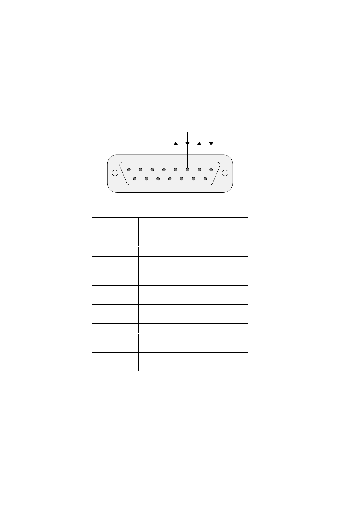
HOST port—RS-232 C
RTS CTS TX RX
GND
8 7 6 5 4 3 2 1
15 14 13 12 11 10 9
MCS 15-pin subD female connector
pin function
1 receive data (RS-232 C)
2 transmit data (RS-232 C)
3 clear to send (RS-232 C)
4 request to send (RS-232 C)
5 not connected
6 not connected
7 not connected
8 not connected
9 not connected
10 reserved Current Loop
11 reserved Current Loop
12 reserved Current Loop
13 signal ground (RS-232 C)
14 reserved Current Loop
15 reserved Current Loop
MS/3300/IG/10/E/970831C-4
Page 57
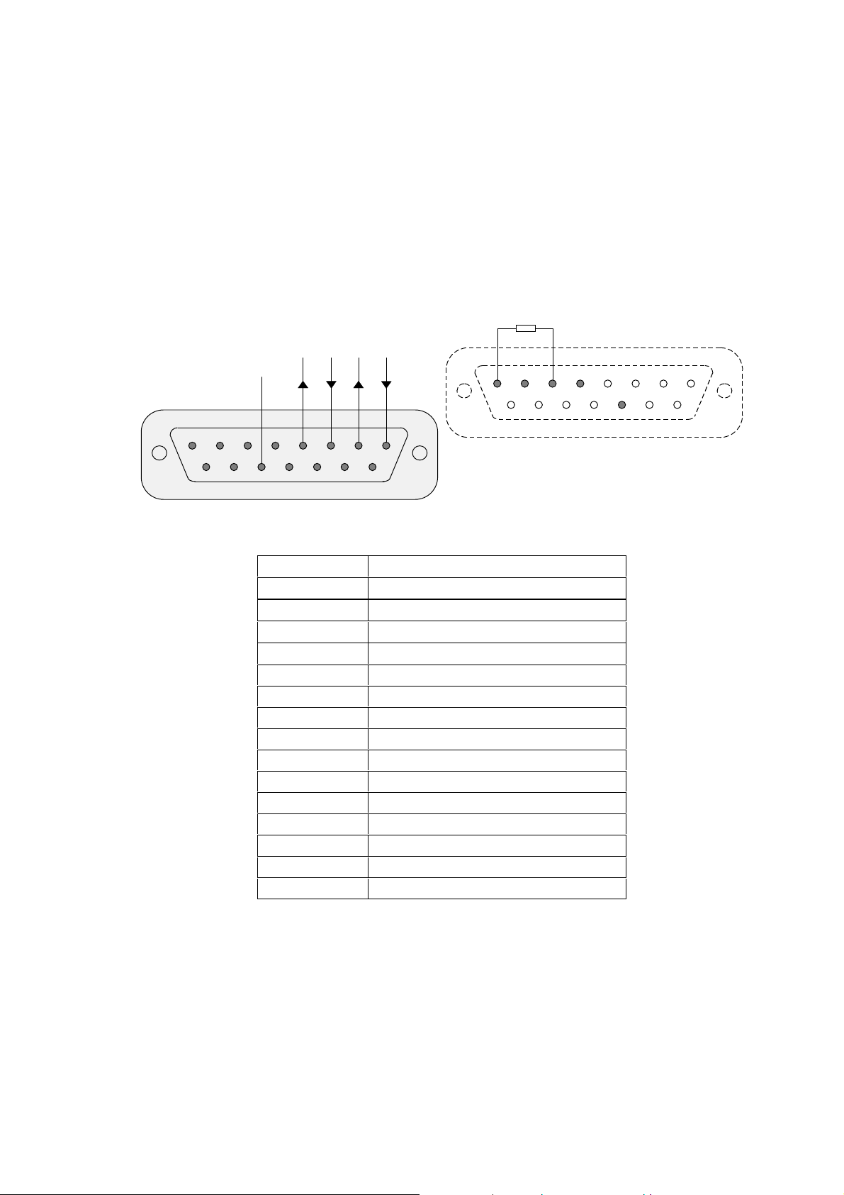
HOST port—RS-422
TX+ RX+ TX- RX-
GND
8 7 6 5 4 3 2 1
15 14 13 12 11 10 9
MCS 15-pin subD female connector
pin function
1 receive data RX- (RS-422)
2 transmit data TX- (RS-422)
3 receive data RX+ (RS-422)
4 transmit data TX+ (RS-422)
5 not connected
6 not connected
7 not connected
8 not connected
9 not connected
10 reserved Current Loop
11 reserved Current Loop
12 reserved Current Loop
13 signal ground (RS-422)
14 reserved Current Loop
15 reserved Current Loop
C. MaxiScan Connexion System (MCS)
RS-422: install resistor = 100 Ohm
1 2 3 4 5 6 7 8
9 10 11 12 13 14 15
host male subD cable connector
MS/3300/IG/10/E/970831 C-5
Page 58
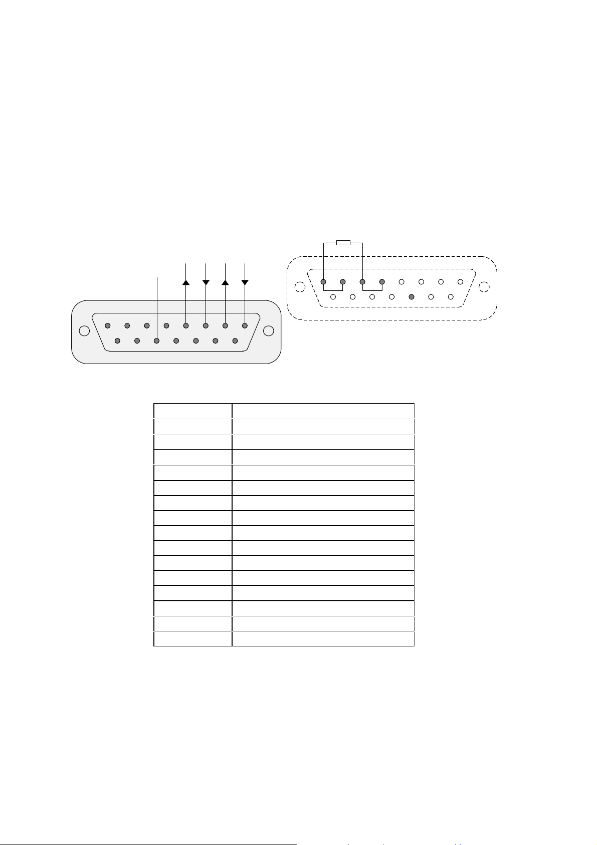
C. MaxiScan Connexion System (MCS)
HOST port—RS-485
RS-485: connect pins 1 and 2 and c onnect pins 3 and 4
TX+ RX+ TX- RX-
GND
8 7 6 5 4 3 2 1
15 14 13 12 11 10 9
MCS 15-pin subD female connector
pin function
1 receive / transmit data RX- / TX- (RS-485)
2 receive / transmit data RX- / TX- (RS-485)
3 receive / transmit data RX+ / TX+ (RS-485)
4 receive / transmit data RX+ / TX+ (RS-485)
5 not connected
6 not connected
7 not connected
8 not connected
9 not connected
10 reserved Current Loop
11 reserved Current Loop
12 reserved Current Loop
13 signal ground (RS-485)
14 reserved Current Loop
15 reserved Current Loop
install resistor = 120 Ohm between pins 1 and 3
1 2 3 4 5 6 7 8
9 10 11 12 13 14 15
host male subD cable connector
MS/3300/IG/10/E/970831C-6
Page 59
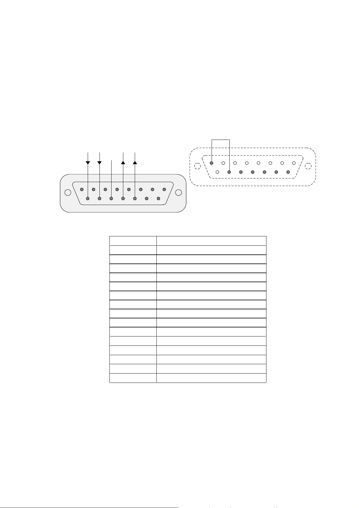
C. MaxiScan Connexion System (MCS)
HOST port—Current Loop (passive type)
Current Loop: connect pins 1 and 10
RX- RX+ TX- TX+
GND
8 7 6 5 4 3 2 1
15 14 13 12 11 10 9
MCS 15-pin subD female connector
pin function
1 reserved
2 reserved RS-232 C / RS-422 / 485
3 reserved RS-232 C / RS-422 / 485
4 reserved RS-232 C / RS-422 / 485
5 not connected
6 not connected
7 not connected
8 not connected
9 not connected
10 reserved
11 TX+ (Current Loop)
12 TX- (Current Loop)
13 signal ground (Current Loop)
14 RX+ (Current Loop)
15 RX- (Current Loop)
1 2 3 4 5 6 7 8
9 10 11 12 13 14 15
host male subD cable connector
MS/3300/IG/10/E/970831 C-7
Page 60
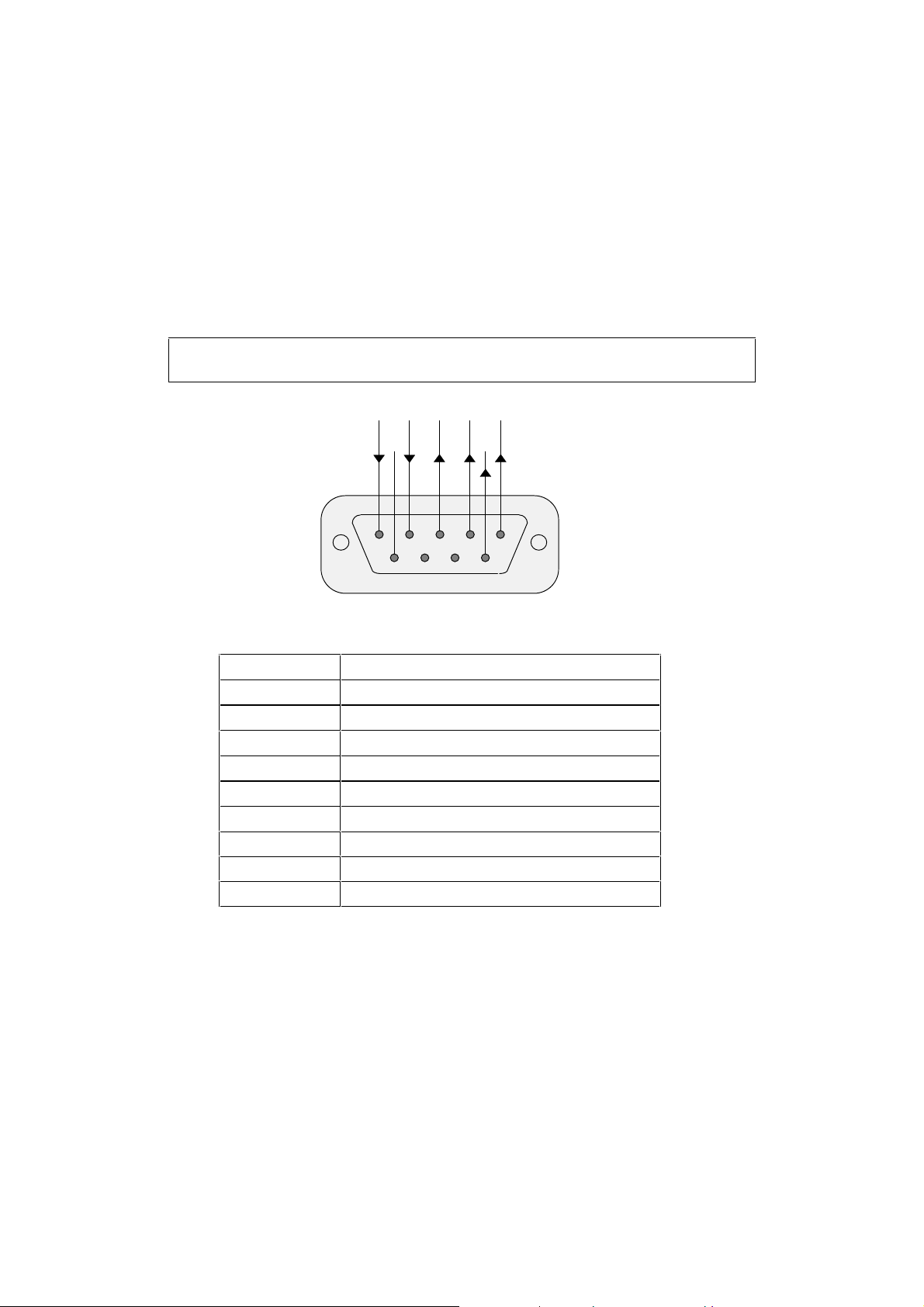
C. MaxiScan Connexion System (MCS)
SYNCHROS port
In all cases, the synchronization current provided by the external input/output device
must be limited to 50 mA max (20 mA is a good average value).
SI- SI+ SO- SO+ +5V
GND
5 4 3 2 1
9 8 7 6
9-pin subD female connector
pin function
1 +5 VDC out (65 mA max)
2 positive synchronization output (SO+) (50 mA max )
3 negative synchronization output (SO-) (50 mA max)
4 positive synchronization input (SI+) (50 mA max)
5 negative synchronization input (SI-) (50 mA max)
6 7-25 VDC 10 Watt
7 not connected
8 not connected
9 power ground
7-25V
pwr
MS/3300/IG/10/E/970831C-8
Page 61
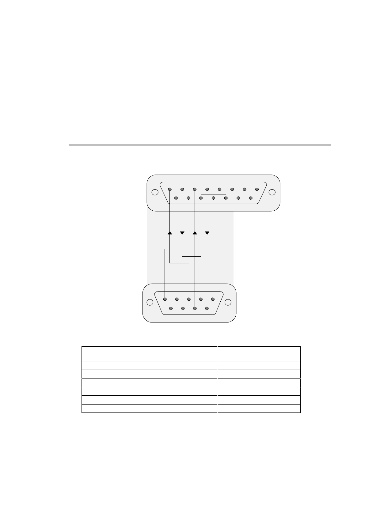
D Standard RS-232 C cable
cable connector - 15-pin subD male
MaxiScan Connexion System side
1 2 3 4 5 6 7 8
9 10 11 12 13 14 15
RS-232 C shielded cable
(shielding connected to
casing of cable connectors)
cable connector - 9-pin subD female
DB 15 male
MaxiScan Connexion System side
1RX3
2TX2
3 CTS 7
4 RTS 8
11-13 GND 5
connector casing shielding connector casing
RX TX CTS RTS
GND
5 4 3 2 1
9 8 7 6
PC side
signal
DB 9 female
PC side
MS/3300/IG/10/E/970831 D-1
Page 62

D. Standard RS-232 C cable
MS/3300/IG/10/E/970831D-2
Page 63
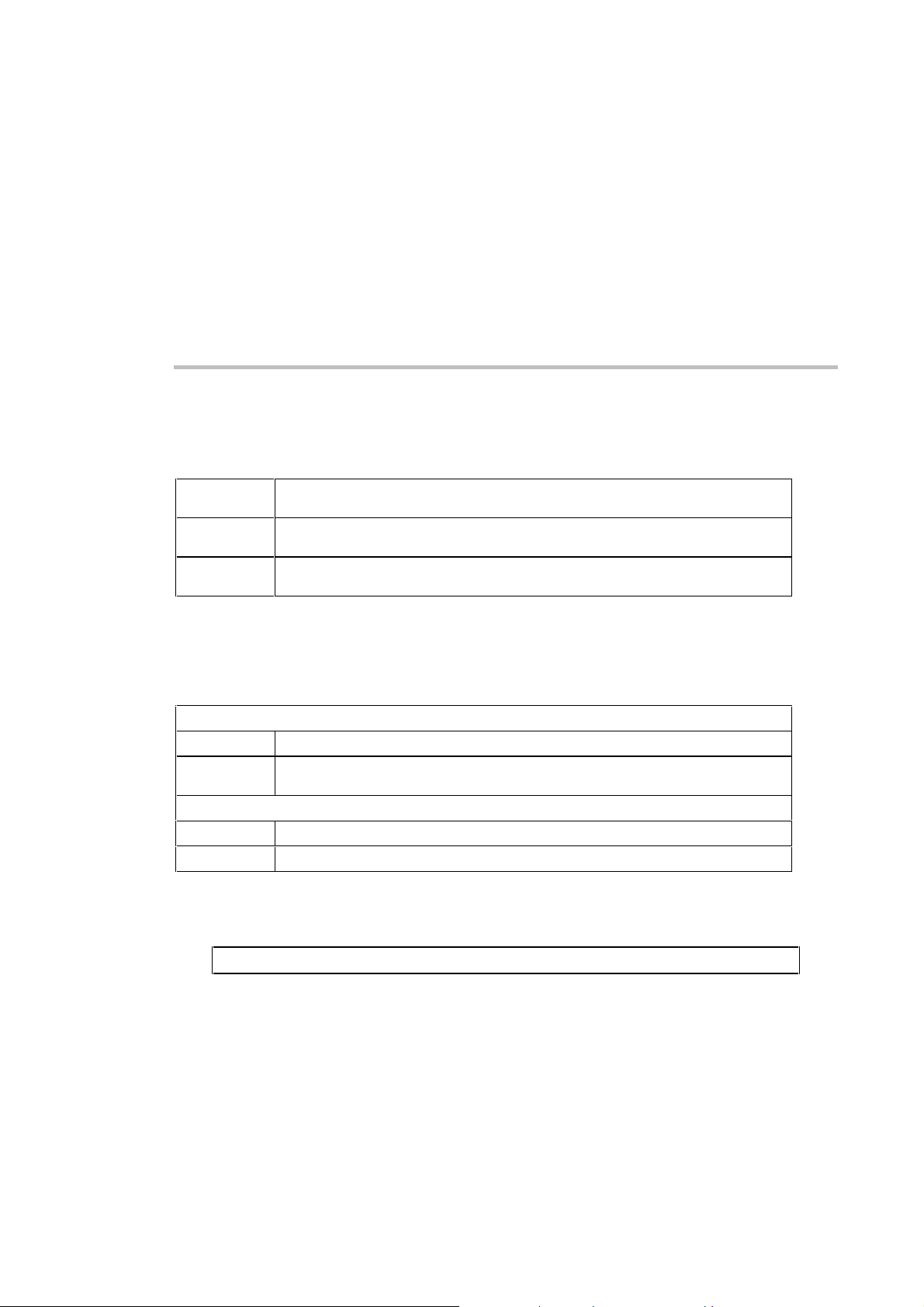
E Input/output synchronization
Input synchronization—Hardware
MaxiScan 3300 trigger event
current on
current off
input pulse
the MaxiScan 3300 starts to read when current flows between inputs SI+ and SI- and
remains active until the current stops flowing
the MaxiScan 3300 starts to read when no current flows between inputs SI+ and SI- and
remains active until current starts to flow
the MaxiScan 3300 starts to read for a programmable duration when a change-of-state
pulse is received through the SYNCHROS input
Output synchronization—Hardware
Hardware synchronization
Output device trigger event
good read
no read
Output device activation current
current on
current off
the output device is activated after a good read
the output device is activated if there is no successful read during an input synchronization
reading session triggered by an input pulse (no read before the end of the read time-out)
the MaxiScan 3300 allows current to flow between outputs SO+ and SOthe MaxiScan 3300 allows no current to flow between outputs SO+ and SO-
Output synchronization—Software
The MaxiScan 3300 can send a message to the host system after a read success or failure.
MS/3300/IG/10/E/970831 E-1
Page 64
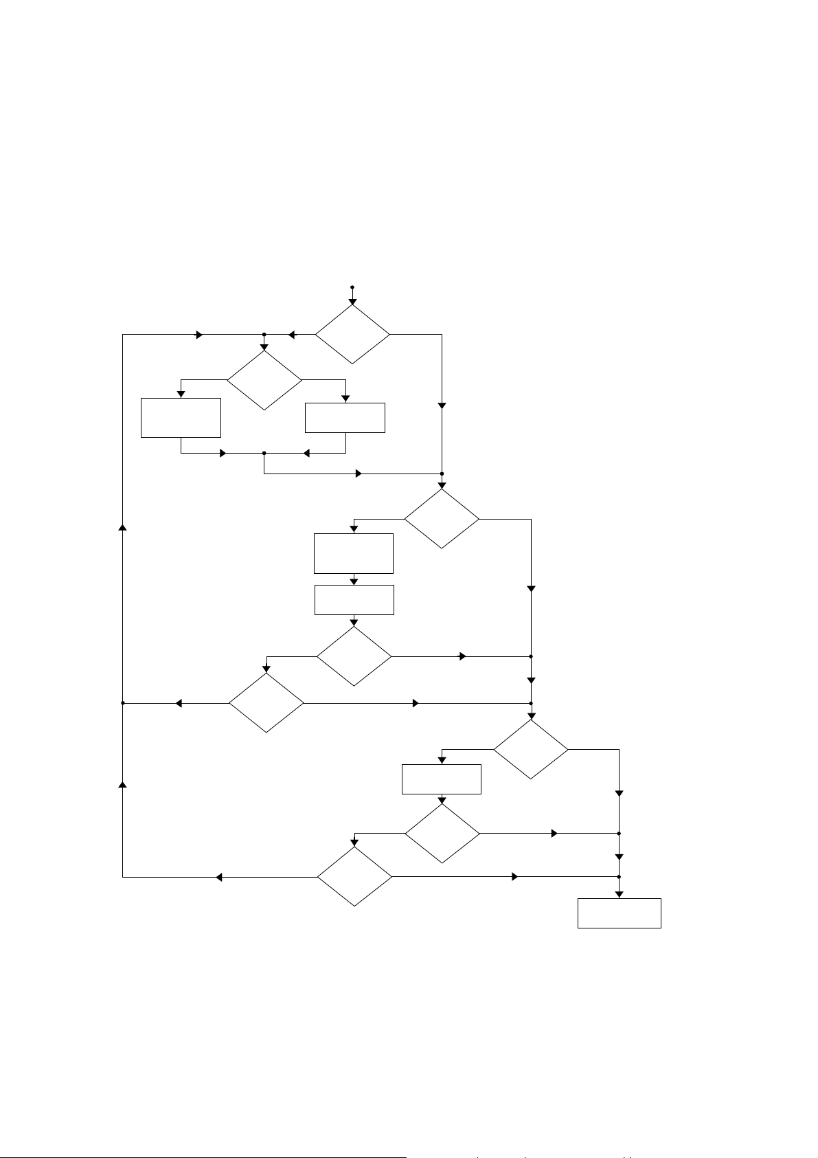
E. Input/output synchronization
Synchronization flowchart
current flow type of input pulse
Select activation:
• current on
current off
•
trigger event
no hardware yes
sync in
yes hardware no
no read Select good read
sync in
Compose read
duration
Select activation:
current on
•
current off
•
Compose active
duration
trigger event
yes hardware no
sync out
no read Select good read
no hardware yes
sync in
yes software no
sync out
Compose message
for host system
trigger event
Test synchronization
setup
MS/3300/IG/10/E/970831E-2
Page 65
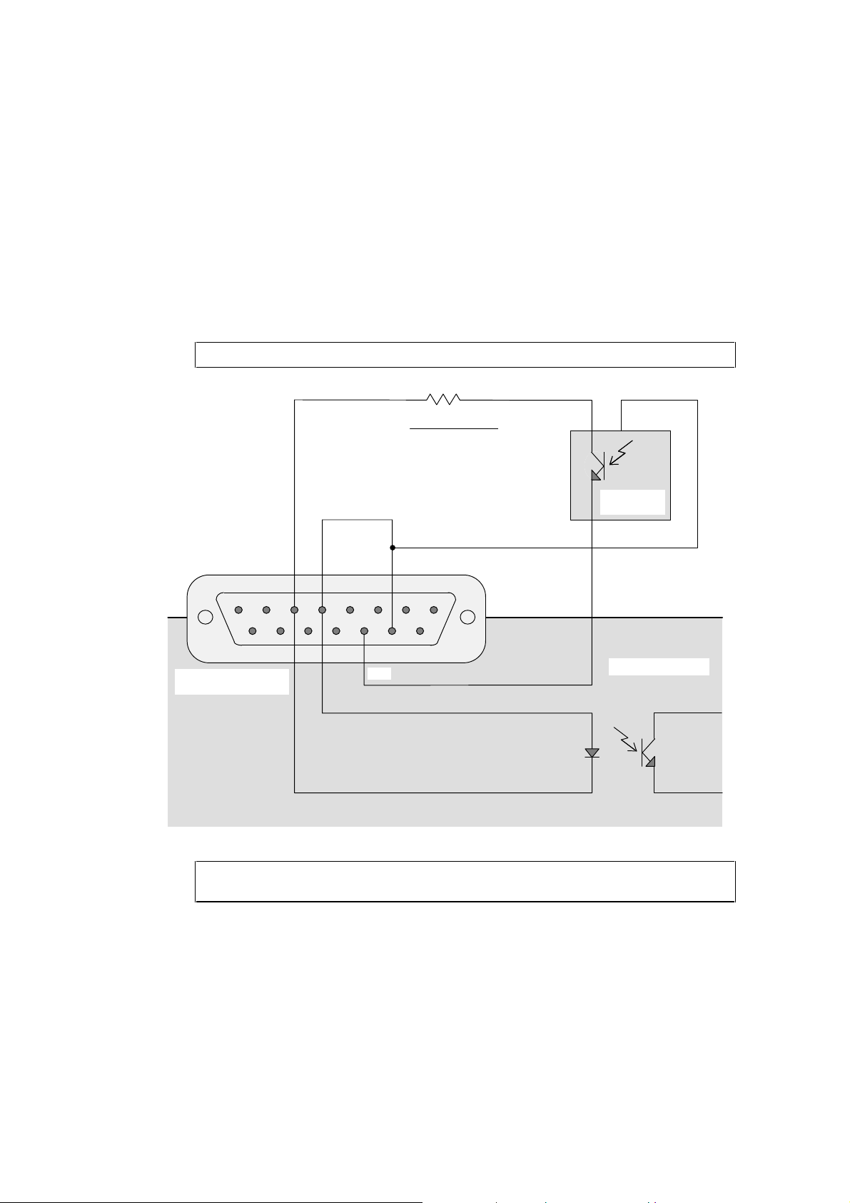
E. Input/output synchronization
Examples
Input synchronization—Direct connection
Example: Reading triggered by an opto-coupled MLV 40-8/28 (VISOLUX) cell.
8 7 6 5 4 3 2 1
15 14 13 12 11 10 9
MaxiScan 3300 15-pin
subD female connector
SI- SI+
V power supply
R = Ω
GND
-3
20.10
7-25 VDC power supply
1 5
photoelectric
sensor
4
MaxiScan 3300
In all cases, the synchronization current provided by the external input device must
be limited to 50 mA max (20 mA is a good average value).
MS/3300/IG/10/E/970831 E-3
Page 66
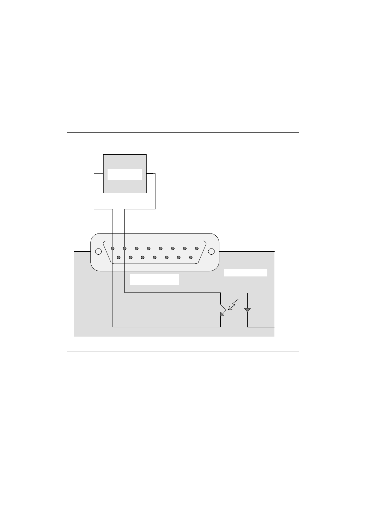
E. Input/output synchronization
Output synchronization—Direct connection
Example: Opto-coupled control output.
conveyor
command block
SO- SO+
8 7 6 5 4 3 2 1
15 14 13 12 11 10 9
MaxiScan 3300 15-pin
subD female connector
MaxiScan 3300
The synchronization current provided by the external output device must be limited to
50 mA max (20 mA is a good average value).
MS/3300/IG/10/E/970831E-4
Page 67
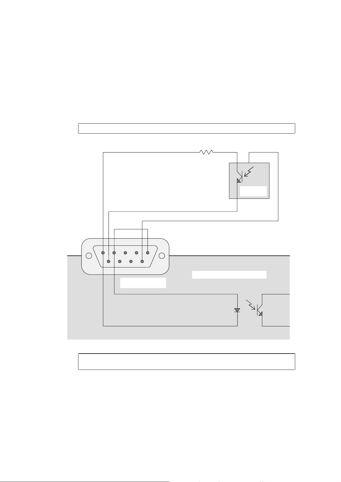
E. Input/output synchronization
Input synchronization—MCS connection unit
Example: Reading triggered by an opto-coupled MLV 40-8/28 (VISOLUX) cell.
330 Ohms
GND
7-25 VDC power supply
SI- SI+ +5V (65 mA max)
5 4 3 2 1
1 5
photoelectric
sensor
4
9 8 7 6
MaxiScan Connexion System
SYNCHROS 9-pin subD
female connector
In all cases, the synchronization current provided by the external input device must
be limited to 50 mA max (20 mA is a good average value).
MS/3300/IG/10/E/970831 E-5
Page 68
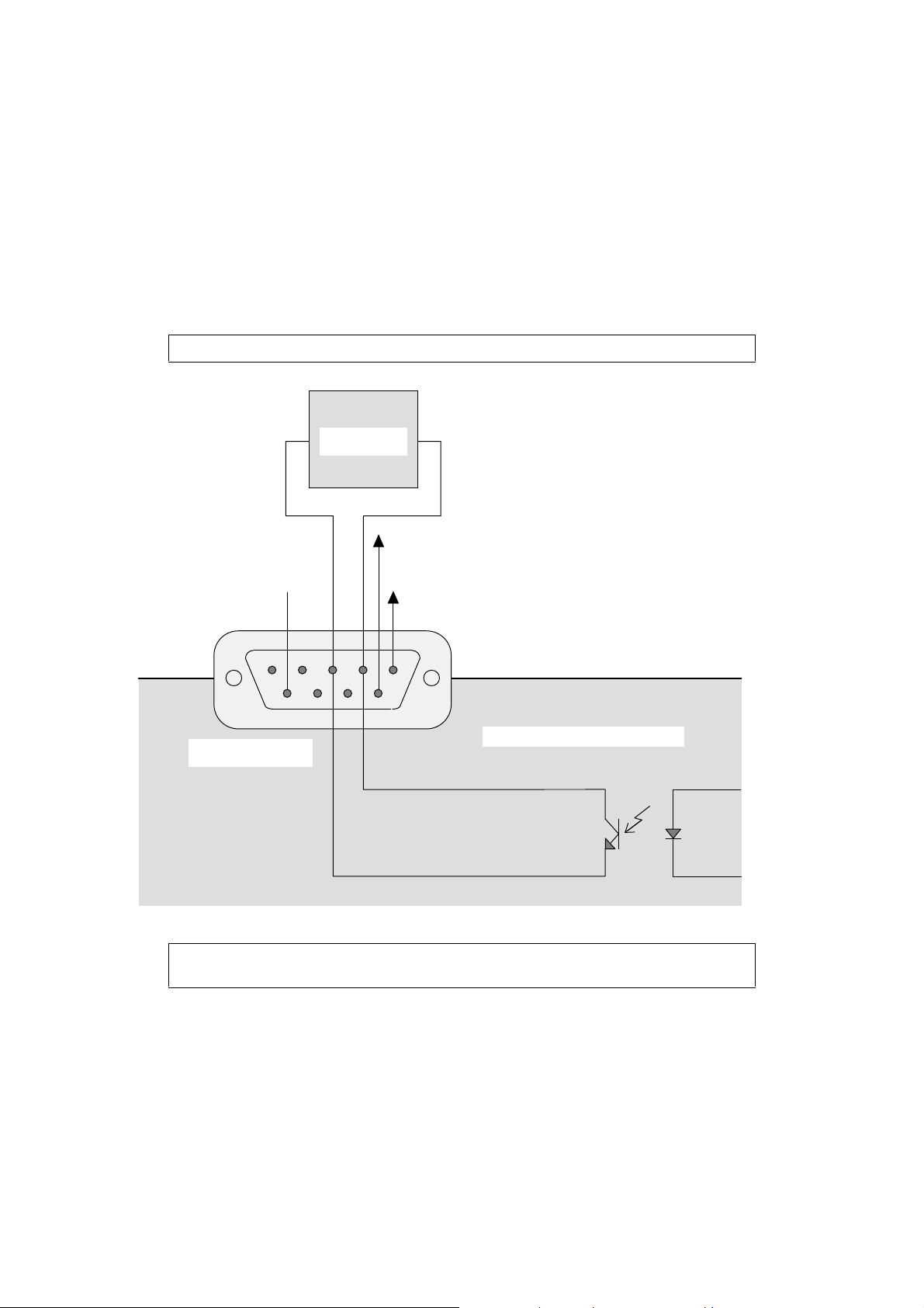
E. Input/output synchronization
Output synchronization—MCS connection unit
Example: Opto-coupled control output.
conveyor
command block
7-25 VDC power supply
GND SO- SO+ +5V (65 mA max)
5 4 3 2 1
9 8 7 6
SYNCHROS 9-pin subD
female connector
MaxiScan Connexion System
The synchronization current provided by the external output device must be limited to
50 mA max (20 mA is a good average value).
MS/3300/IG/10/E/970831E-6
Page 69
F If you have a problem . . .
This appendix describes things you can try if you have problems with your MaxiScan 3300
during power-up, configuration and normal operation.
If you can not solve the problem yourself, please contact your UBI representative.
Before you contact your UBI representative . . .
Look in the following checklists if you have any of the following problems:
• no LEDs
• no beeps
• error beeps
• no transmission
• incorrect transmission
Setup problems—Checklist
system connected up correctly
system switched on
correct power-up beep indication—2 beeps
default configuration inhibit af ter 1 minute option is active—if
you are using a setup sheet, you must switch off / switch on the
MaxiScan 3300 to be able to read configuration codes if the
1-minute configuration timeout has expired
MS/3300/IG/10/E/970831 F-1
Page 70

F. If you have a problem . . .
Reading problems—Checklist
correct symbologies selected for the bar codes you are trying to
read
symbologies you read are available for your MaxiScan 3300
all unnecessary symbologies disabled
continuous configuration mode disabled (configuration i nhibit
after 1 minute selected)
barcode length compatible with minimum / fixed length parameter
settings of MaxiScan 3300
MaxiScan 3300 configured for check digit and no check digit
present in code
barcode quality, damaged or poorly printed codes, "fragile"
symbologies—read the appropriate test code to see if there is a
problem with the symbology (Appendix G)
Transmission problems—Checklist
all unnecessary symbologies disabled
continuous configuration mode disabled (configuration i nhibit
after 1 minute selected)
correct RS-232 data transmission settings selected
inter-character delay value required if transmitted data incomplete
or incorrect
MS/3300/IG/10/E/970831F-2
Page 71
F. If you have a problem . . .
Try a general reset of the MaxiScan 3300 . . .
If you do not find a solution after checking the above points, you can try a general reset of
the MaxiScan 3300.
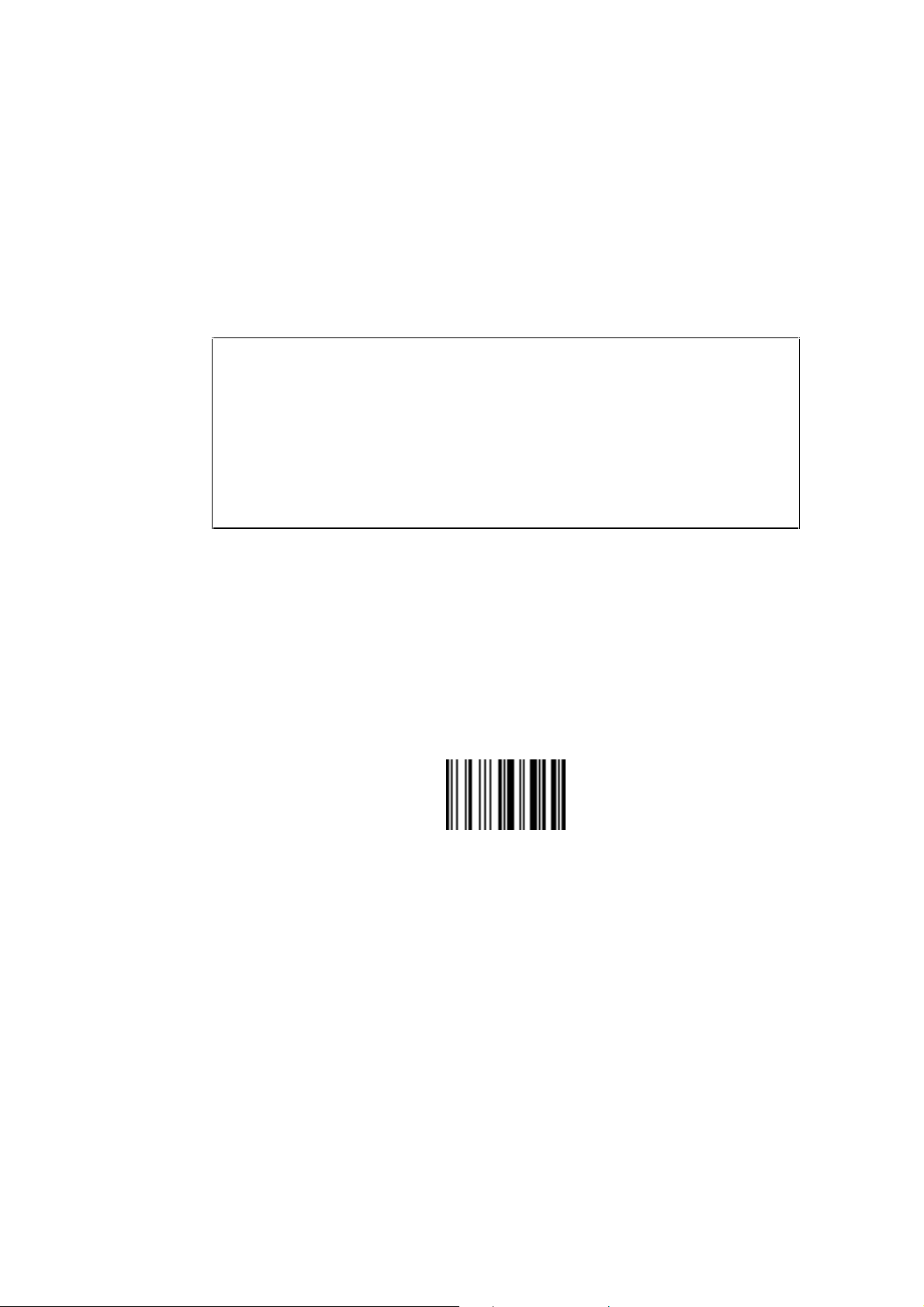
Reset Factory Defaults resets all the MaxiScan 3300 operating parameters to their factory
default settings:
• default RS-232 C data transmission settings,
• default symbologies and symbology settings,
• default MaxiScan 3300 operating settings (scan patterns, contrast level, resolution
adjustment (video channel selection), . . .).
After a general reset, you will have to re-enter any custom settings if applicable.
1. Disconnect the MaxiScan 3300 power supply.
2. Prepare the MaxiScan 3300 for online setup—connect the standard
RS-232 C cable between the HOST port of the MaxiScan Connexion
System and the serial port of your PC if it is not already connected.
3. Position the Reset Factory Defaults code at a good reading distance in
front of the MaxiScan 3300 and reconnect the MaxiScan 3300 power
supply.
Reset Factory Defaults
4. Start up the EasySet System configuration software.
5. Use EasySet System to download your complete setup to the
MaxiScan 3300 (see section 5, Setting up your MaxiScan 3300).
If you still have a problem . . .
Contact your UBI representative and give full details of the problem.
MS/3300/IG/10/E/970831 F-3
Page 72

F. If you have a problem . . .
MS/3300/IG/10/E/970831F-4
Page 73
G Test codes
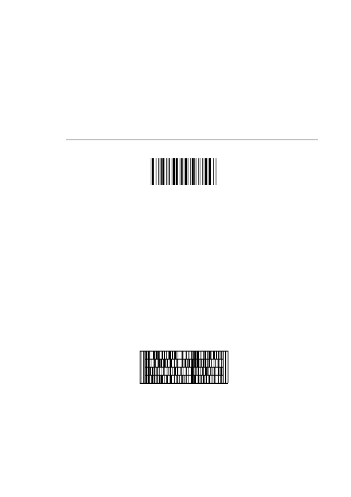
Codabar
123456
Codablock F
UBI ScanPlus XP and XP PDF
CCD Bar Code Scanners
MS/3300/IG/10/E/970831 G-1
Page 74

G. Test codes
Code 39
CODE-39
Code 93
CODE-93
MS/3300/IG/10/E/970831G-2
Page 75

Code 128
CODE-128
G. Test codes
EAN 128
(]C1)EAN 128
MS/3300/IG/10/E/970831 G-3
Page 76

G. Test codes
EAN-8
12345670
EAN-13
1234567890128
MS/3300/IG/10/E/970831G-4
Page 77

UPC-E
012345
0
G. Test codes
7
UPC-A
01234 50000
0
MS/3300/IG/10/E/970831 G-5
7
Page 78

G. Test codes
Standard 2 of 5
123456
MS/3300/IG/10/E/970831G-6
Page 79

Interleaved 2 of 5
G. Test codes
12345678901234
Matrix 2 of 5
012345
MS/3300/IG/10/E/970831 G-7
Page 80

G. Test codes
MSI Code
12345666
Plessey Code
80001495050
MS/3300/IG/10/E/970831G-8
Page 81

MS/3300/IG/10/E/970831
Page 82

Ammendale Technology Park
UBI Inc.
12240 Indian Creek Court
Beltsville
MD 20705
USA
Tel: +1 301 210 3000
Fax: +1 301 210 5498
UBI Ltd
Attenborough House
15 Bennet Road
Reading
Berkshire RG20QX
ENGLAND
Tel: +44 118 9876594
Fax: +44 118 9876305
UBI International / UBI France SA
Immeuble "Le Newton"
23 avenue de l’Europe
78402 Chatou Cedex
FRANCE
Tel: +33 (0)1.30.15.25.35
Fax: +33 (0)1.34.80.14.33
UBI GmbH
Max-Planck-Strasse 9-13
D-85716 Unterschleissheim/München
GERMANY
Tel: +49 89 32 18 10 00
Fax: +49 89 32 18 10 20
UBI Danmark AS
Hovedvejen 122
2600 Glostrup
DENMARK
Tel: +45 43 43 90 72
Fax: +45 43 63 90 72
UBI OY
Valkjärventie 1
02130 Espoo
FINLAND
Tel: +358 90 52 37 21
Fax: +358 90 52 92 24
UBI SrL
Via Speranza 35
40068 San Lazzaro di Savena
Bologna
ITALY
Tel: +39 51 453270
Fax: +39 51 450460
UBI Nordic AB
Bredgatan 10
222 21 Lund
SWEDEN
Tel: +46 46 350 660
Fax: +46 46 350 661
UBI Norge A/S
Postboks 33
1483 Skytta
NORWAY
Tel: +47 67 06 03 20
Fax: +47 67 06 05 01
UBI Russia
Kamennoostrovskii Prospect 29-2
St Petersburg 197 022
RUSSIA
Tel: +7 812 232 81 39
Fax: +7 812 119 13 82
UBI representative:
MS/3300/IG/10/E/970831 UBI Part Number: 0-530049-01-10
 Loading...