

UBI EasyCoder 501 SA, EasyCoder 501XP, EasyCoder 601, EasyCoder 501 Installation Instructions Manual
Page 1
EasyCoder 501/601 – Installation Instructions
1
Note:
Illustrations show an EasyCoder 501.
The principles for fitting this optional
equipment in an EasyCoder 601 are
exactly the same.
Type
Art. No.
Ser. No.
115/230 V 2.6/1.3 A 50–60 Hz
INDUSTRIAL INTERFACE KIT
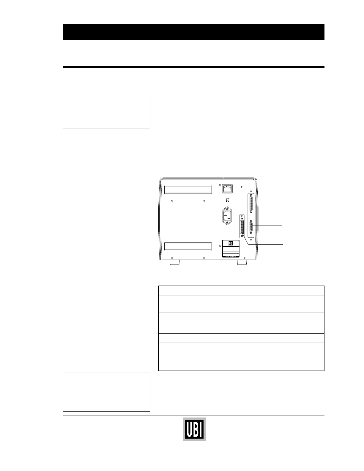
The Industrial Interface Board adds one serial communication port
("uart3") and one connector with four IN and four OUT ports to the
standard serial communication port ("uart1:").
The IN/OUT ports provide an interface between the printer and
various types of external equipment, such as gates, conveyor belts,
wrappers etc. The input and output signals can be read or initiated
by means of UBI Fingerprint instructions. Thereby the printer can
be used to control the external devices – or be controlled by them –
according to the program.
The printer's software detects when an Industrial Interface Board is
installed and adds communication and buffer setup options for the
communication port "uart3:".
When an Industrial Interface Board is fitted, the following types of
interfaces become available:
"uart1:"
Fitted on printer's CPU board.
RS 232C Standard. Selected by strap.
RS 422 or 20 mA CL Option. Additional circuits required.
"uart3:"
Fitted on Industrial Interface Board.
RS 232C
IN/OUT connector
Fitted on Industrial Interface Board.
4 input channels The software can read the status of four different
input signals.
4 output channels The software can set four different signals to either
open or closed contact and also read their status.
The Industrial Interface Kit consists of:
1 Interface board assy.
2 Screws MRX-Z 3
× 6 FZB (not intended for EasyCoder 501/601)
Installation Instructions
Introduction
UBI EasyCoder 501/601
Industrial Interface Kit
Installation Instructions
Edition 1, March 1994
Article No. 1-960343-01
"uart1:"
IN/OUT ports
"uart3:"
Page 2
EasyCoder 501/601 – Installation Instructions
2
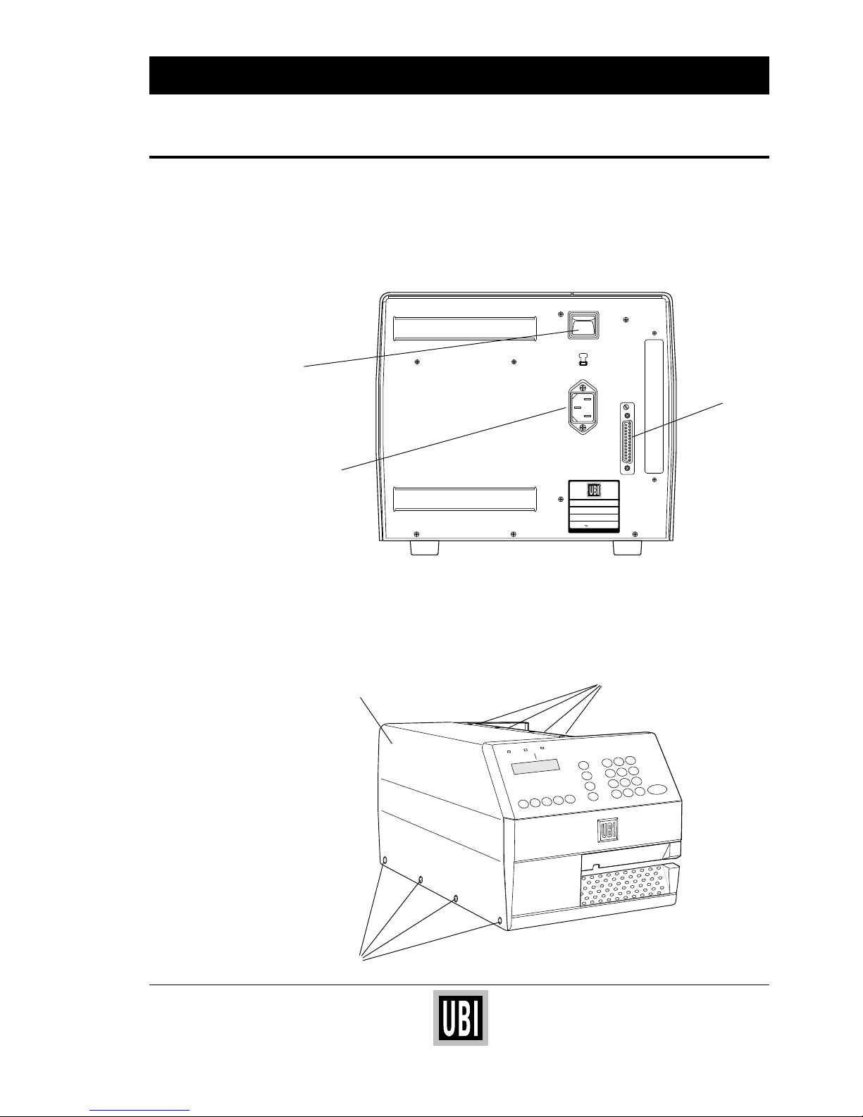
The only tool required is a Torx #T10 screwdriver.
❑ Turn off the power and remove the power cord.
❑ Remove the communication cable from communication port
"uart1:".
❑ Open the right hand door.
❑ Remove the eight Torx screws that hold the cover over the left
part of the printer (see illustration below).
❑ Remove the cover.
Continued!
INDUSTRIAL INTERFACE KIT, cont'd.
Step-by-Step Installation
Instructions
Communication
Port "uart1:"
0
230V
MADE IN SWEDEN
Type
Art. No.
Ser. No.
115/230 V 2.6/1.3 A 50–60 Hz
TA
Power
Switch
Power Cord
Receptacle
F1 F2 F3 F4 F5
Pause
Setup
Feed
Enter
7 8 9
4 5 6
1 2 3
. 0 C
Print
Power
Ready
Error
EasyCoder 501 E
Screws (4x)
Cover
Screws (4x)
Page 3
EasyCoder 501/601 – Installation Instructions
3
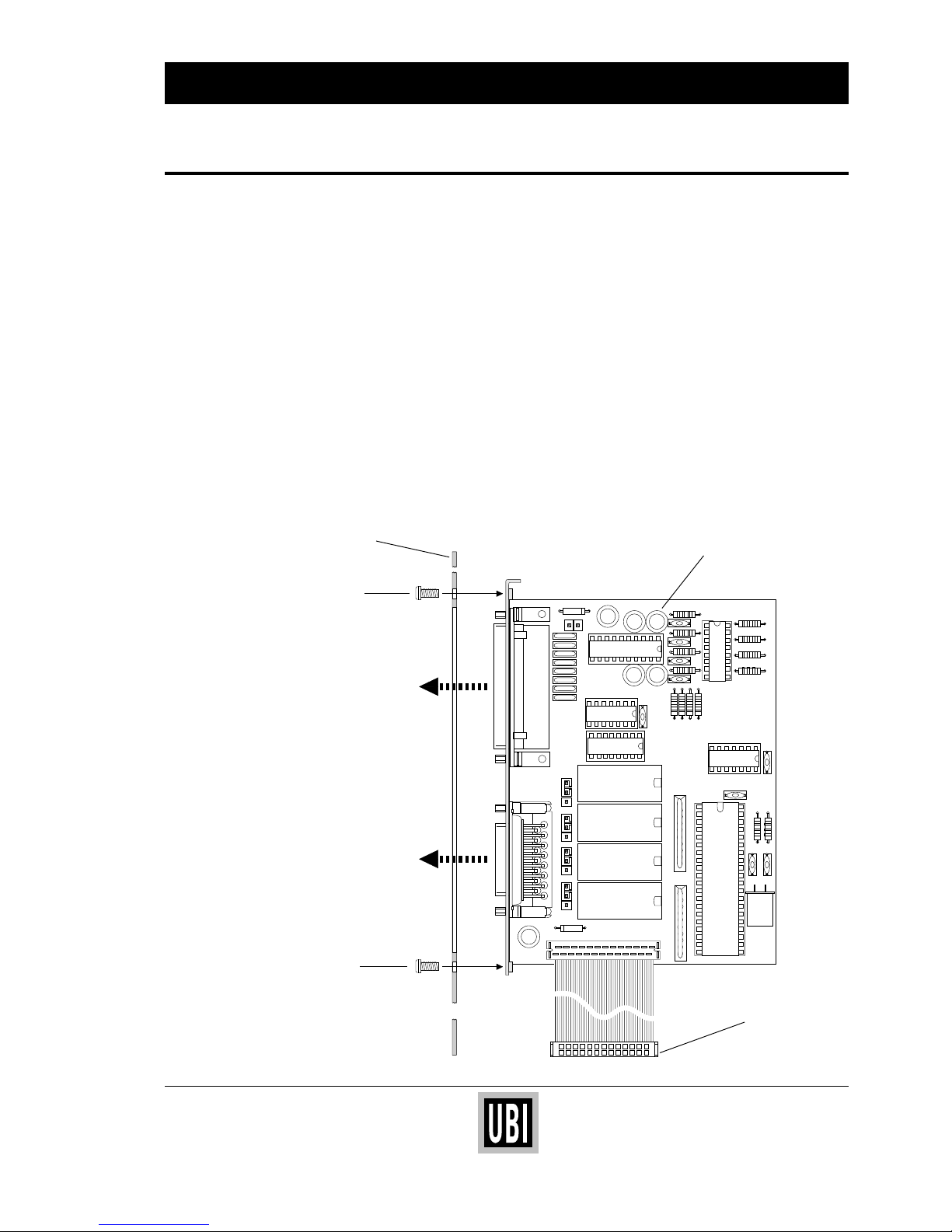
❑ Remove the existing cover plate.
❑ Make sure that the CPU board is strapped and equipped for the
desired type of communication on "uart1:" (see the EasyCoder
501 or EasyCoder 601 Technical Description). Once the inter-
face board has been fitted, it will be difficult to access the rear
part of the CPU board.
❑ Fit the required straps on the Industrial Interface Board as
described on page 5.
❑ Connect the cable from the interface board to connector P-4 at
the bottom rear corner of the CPU board. Be careful so the
interface board and the CPU board do not come in contact with
each other, which possibly may cause damage or short-circuiting.
❑ Fit the interface board assembly to the printer's rear plate from
the inside as illustrated below using the same screws that held the
removed cover plate.
Continued!
INDUSTRIAL INTERFACE KIT, cont'd.
Step-by-Step Installation
Instructions, cont'd.
P2P6P7P8
123123123123
P1
Industrial
Interface Board
Connect to P-4
on CPU Board
Rear Plate
Screw
Screw
Female DB15
I/O Connector
Female DB25
Connector
"uart3:"
Page 4
EasyCoder 501/601 – Installation Instructions
4
INDUSTRIAL INTERFACE KIT, cont'd.
Continued!
Step-by-Step Installation
Instructions, cont'd.
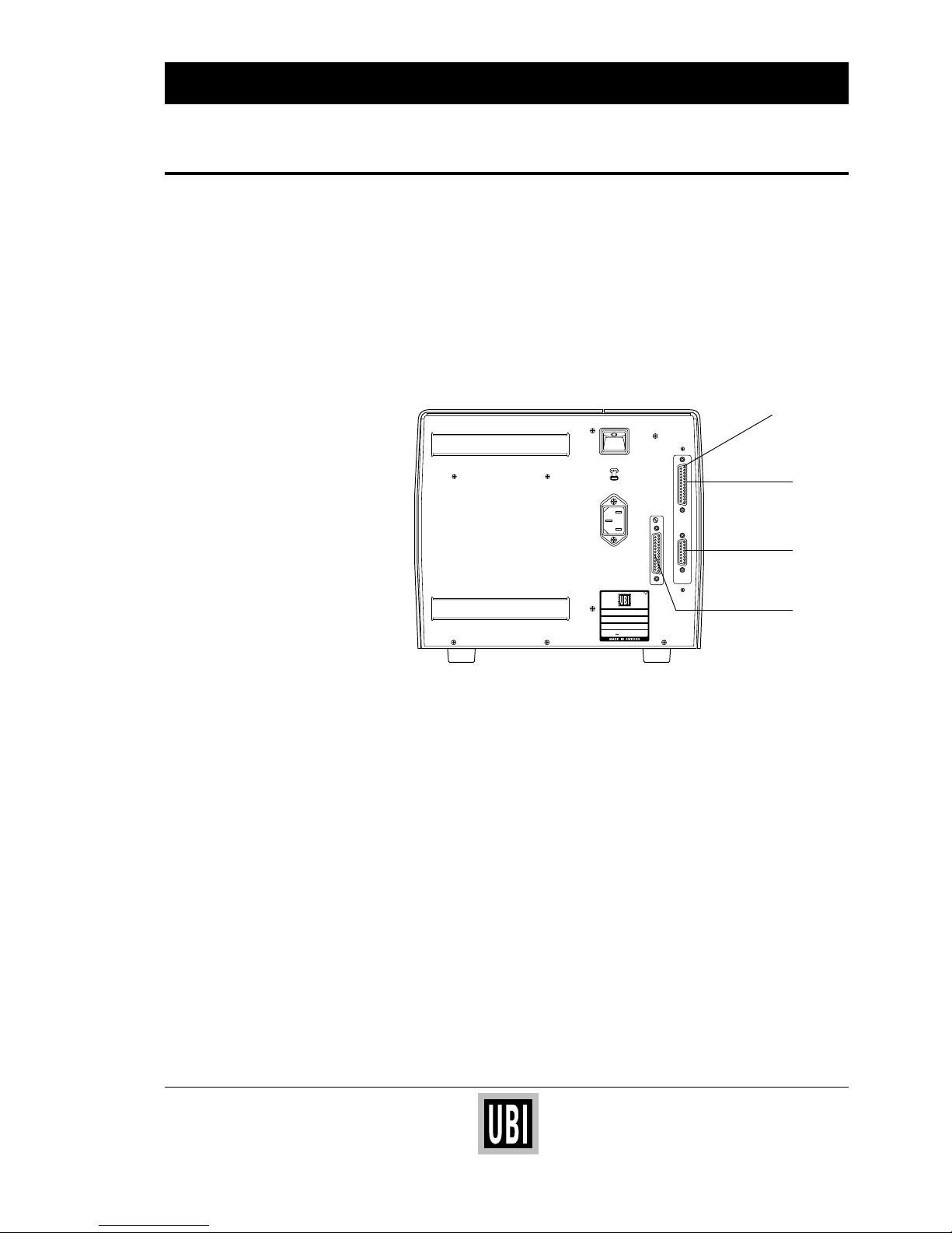
❑ Reassemble the printer in reverse order.
❑ Connect the communication cables to their respective connec-
tors. Please refer to page 6 for pinout descriptions.
❑ Connect the power cord and turn on the power.
❑ If you intend to use the communication port "uart3:" (RS 232C),
set up its communication and buffer parameters as described in
the EasyCoder 501 or EasyCoder 601 Technical Description.
Type
Art. No.
Ser. No.
115/230 V 2.6/1.3 A 50–60 Hz
"uart1:"
"uart3:"
IN/OUT
Ports
Industrial Interface
Board Assy.
Page 5
EasyCoder 501/601 – Installation Instructions
5
INDUSTRIAL INTERFACE KIT, cont'd.
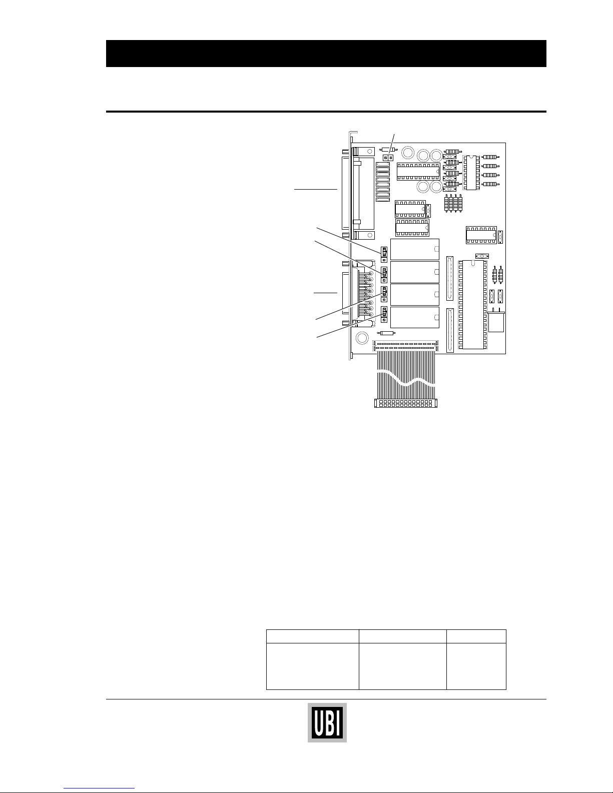
Straps
Communication Port "uart3:"
RS 232C:
There are no straps for controlling the RS 232C interface on
"uart3:".
External +5V:
External +5V ( max. 200 mA) can be made available on pin 16 by
fitting a strap on P-1.
Be careful not to enable this option unintentionally, which may
cause harm to the connected terminal, computer or other device.
In/OUT Connector
In/Out port 201-204:
One relay for each port switches the
OUT signal to open or closed
as
PORTOUT ON/OFF statements are executed in the program.
Four straps, P-2, P-6, P-7 and P-8, control the relation between
relay and output signal on output ports 201–204 respectively:
PORTOUT stmt Strap between pins OUT signal
PORTOUT (<nexp>) ON 1–2 (upper position) Open
PORTOUT (<nexp>) ON 2–3 (lower position) Closed
PORTOUT (<nexp>) OFF 1–2 (upper position) Closed
PORTOUT (<nexp>) OFF 2–3 (lower position) Open
P4
P2
P3
P5
P6P7P8
123123123123
P1
"uart3:"
I/O connector
P-6
P-8
P-1
P-2
P-7
Page 6
EasyCoder 501/601 – Installation Instructions
6
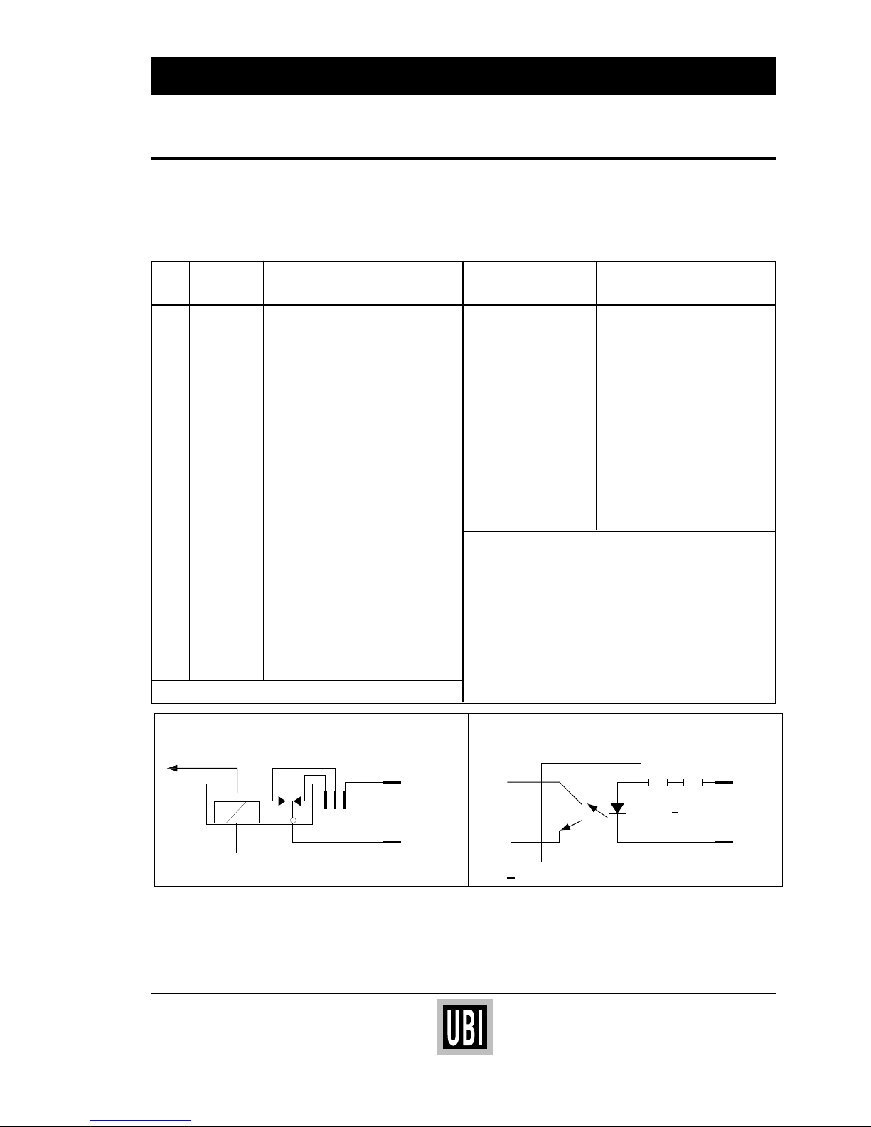
Pin "uart3:" Remarks Pin In/Out connector Remarks
DB25 female DB15 female
1 GNDC Cable shield 1 OUT 201 See example below
2 TXDB Transmitted data from printer 2 OUT 201
3 RXDB Received data to printer 3 OUT 202
4 RTSB RTS from printer 4 OUT 202
5 CTSB CTS to printer 5 OUT 203
6 DRSB DSR to printer 6 OUT 203
7 GNDI Signal ground 7 OUT 204
8 – not used 8 OUT 204
9 – not used 9 IN 101 See example below
10 – not used 10 IN 101
11 – not used 11 IN 102
12 – not used 12 IN 102
13 – not used 13 IN 103
14 – not used 14 IN 104
15 – not used 15 IN 103/104
16 +5VEXT + 5V max 200 mA*
17 – not used
18 – not used
19 – not used
20 DTRB DTR pemanently high
21 – not used
22 – not used
23 – not used
24 – not used
25 – not used
*/. If strap fitted on P-1
INDUSTRIAL INTERFACE KIT, cont'd.
Connector Configuration
"uart3:" is a DB25 female connector.
The In/Out connector is a DB15 female connector.
The mounting holes are connected to chassis ground.
OUT signals are controlled by means of
PORTOUT (<nexp>) ON|OFF statements.
IN and OUT signals are read by means of
PORTIN (<nexp>) functions.
Also see UBI Fingerprint Programmer's Manual.
IN1
9
10
P-3
TIL193B
R5 R6
C10
Example of an IN portExample of an OUT port
+5V
1
2
P-3
REL1
1
OUT1
P-2
32
POWER: max. 240VA
VOLTAGE: max. 60VAC
CURRENT: max. 4A
VOLTAGE: 10–48V
CURRENT: 3–16mA
Information in this manual is subject to change without prior notice and does not represent a commitment
on the part of UBI Printer AB.
© Copyright UBI Printer AB, 1994. All rights reserved. Published in Sweden.
EasyCoder is a trademark of United Barcode Industries (UBI).
Torx is a registered trademark of Camcar Division of Textron Inc.
 Loading...