

Page 1

1
UBI EasyCoder 401 Linerless – Technical Manual
Introduction Contents ..................................................................................................... 1
FCC, DOC and VDE Notices ..................................................................... 3
Preface ....................................................................................................... 4
Models EasyCoder 401 Linerless Tear-Off ............................................................. 5
EasyCoder 401 Linerless Cutter ................................................................. 7
Installation Installation Check List ................................................................................ 9
Unpacking ................................................................................................ 10
Mains Connection..................................................................................... 11
Computer Connection............................................................................... 12
Starting Up Startup Files ............................................................................................. 13
Turning On the Printer .............................................................................. 13
Messages at Startup .................................................................................. 14
Setup Parameters General Information ................................................................................. 15
Contrast .................................................................................................... 16
Serial Communication .............................................................................. 16
Detection .................................................................................................. 19
Media Size ............................................................................................... 22
Print Window (printhead in left-hand position) ......................................... 23
Print Window (printhead in right-hand position) ....................................... 24
Media Type .............................................................................................. 25
Print Defines............................................................................................. 25
Performance ............................................................................................. 26
Memory Allocation .................................................................................. 26
Setting Up
EasyCoder 401 Linerless
Different Methods .................................................................................... 27
Printing Principles General Information ................................................................................. 28
Direct Thermal Printing ............................................................................ 28
Printhead Pressure Adjustment ................................................................. 28
Dot Size.................................................................................................... 30
Conversion Table ..................................................................................... 30
Linerless Direct Thermal Paper General Information ................................................................................. 31
Selecting Paper Setup Options ........................................................................................... 32
Paper Dimensions Roll Size ................................................................................................... 33
Linerless Strip w/o Marks ......................................................................... 34
Perforated Strip w. Marks ......................................................................... 35
Non-Perforated Strip w. Marks ................................................................. 36
Label-Taken Sensor General Information ................................................................................. 37
Adjusting the Sensitivity........................................................................... 38
Program Example ..................................................................................... 39
Paper Jam Detection in Cutter................................................................... 39
Linerless Paper Cutter General Information ................................................................................. 40
Controlling the Cutter ............................................................................... 41
Cleaning ................................................................................................... 42
Scalable Fonts Kit General Information ................................................................................. 43
Scaling Fonts in UBI Fingerprint.............................................................. 43
Downloading Outline Font Files from a PC .............................................. 44
Printout Samples....................................................................................... 45
CONTENTS
UBI EasyCoder 401 Linerless
Technical Manual
UBI Fingerprint
6.1
Edition 1, March 1996
Art. No. 1-960409-00
Continued!
Page 2

2
UBI EasyCoder 401 Linerless – Technical Manual
CONTENTS, cont'd.
Electronics Accessing the CPU Board ........................................................................ 46
CPU Board ............................................................................................... 47
UBI Fingerprint EPROMs........................................................................ 48
Configuration EPROMs ........................................................................... 48
ROM-expansion EPROMs ....................................................................... 48
RAM memory .......................................................................................... 49
Real-time Clock Circuit ............................................................................ 49
Fuse.......................................................................................................... 49
Potentiometers .......................................................................................... 50
Interfaces Communication Port "uart1:".................................................................... 52
RS 232C (V24) on "uart1:" ....................................................................... 53
RS 422 on "uart1:".................................................................................... 55
20 mA Current Loop on "uart1:"............................................................... 57
Parallel Interface Board ............................................................................ 60
Page 3
3
UBI EasyCoder 401 Linerless – Technical Manual
FCC Notice
United States of America
WARNING:
This equipment generates, uses, and can radiate radio frequency energy and if not installed and used in accordance with
the instructions manual, may cause interference to radio communications. It has been tested and found to comply with the
limits for a Class A computing device pursuant to Subpart J of Part 15 of FCC Rules, which are designed to provide
reasonable protection against such interference when operated in a commercial environment. Operation of this equipment
in a residential area is likely to cause interference in which case the user at his own expense will be required to take whatever
measures may be required to correct the interference.
DOC Notice
Canada
Canadian Dept. of Communication
REGULATIONS COMPLIANCE
(DOC-A)
This digital apparatus does not exceed the class A limits for radio noise emissions from a digital apparatus as set out in
the radio interference regulations of the Canadian Department of Communication.
✳ ✳ ✳
Ministère des Communications du Canada
CONFORMITE DE REGLEMENTS
(DOC-A)
Le présent appareil numérique n´émet pas de bruits radio-électriques dépassant les limites applicables aux appareils
numériques de classe A prescrites dans le règlement sur brouillage radioélectrique édicté par le Ministère des
Communications du Canada.
VDE Notice
Germany
ALLGEMEINE VORSCHRIFT:
Reparaturen oder sonstige Eingriffe, die sich nicht auf normale Bedienung der Maschine beziehen, dürfen ausschließlich
nur von einem ausgebildeten, zuständigen Fachmann vorgenommen werden.
Information in this manual is subject to change without prior notice and does not represent a commitment
on the part of UBI Printer AB.
© Copyright UBI Printer AB, 1996. All rights reserved. Published in Sweden.
EasyCoder and LabelShop are trademarks of United Barcode Industries (UBI).
Apple and Macintosh are registered trademarks of Apple Computer Inc.
Bitstream is a registered trademark and Speedo is a trademark of Bitstream, Inc.
Centronics is a registered trademark of Centronics Data Computer Corp.
IBM is a registered trademark of International Business Machines Corporation.
Microsoft, MS, and MS-DOS are registered trademarks of Microsoft Corporation.
Torx is a registered trademark of Camcar Division of Textron Inc.
TrueType is a trademark of Apple Computer Inc.
Windows is a trademark of Microsoft Corporation.
Page 4

4
UBI EasyCoder 401 Linerless – Technical Manual
PREFACE
This Technical Manual is intended to facilitate installation and
setup. It also gives information on linerless labels and paper strip.
This manual is presently supplemented by the following publications:
• EasyCoder 401 Linerless, Operator's Guide
Illustrated step-by-step instructions for paper load as well as daily maintenance. Multilingual.
• EasyCoder 401 Linerless, User's Manual
Gives information on how to run and maintain the printer and how to load
paper supply.
• UBI Shell Standard Startup Manual
Gives information on how to run the UBI Shell startup program.
• UBI Direct Protocol, Programmer's Guide
Introduction to the UBI Direct Protocol, an easy-to-use “slave” protocol for
computer connection.
• UBI Fingerprint, Programmer's Guide
Introduction to the UBI Fingerprint programming language, which is used to
control the printer's functions and the printing.
• UBI Fingerprint, Reference Manual
Contains information on the instructions and other features in the UBI
Fingerprint programming language.
• UBI LabelShop, various manuals
Information on how to use the UBI LabelShop WYSIWYG label-editing
program for Microsoft Windows.
Page 5
5
UBI EasyCoder 401 Linerless – Technical Manual
MODELS EasyCoder 401 LLT
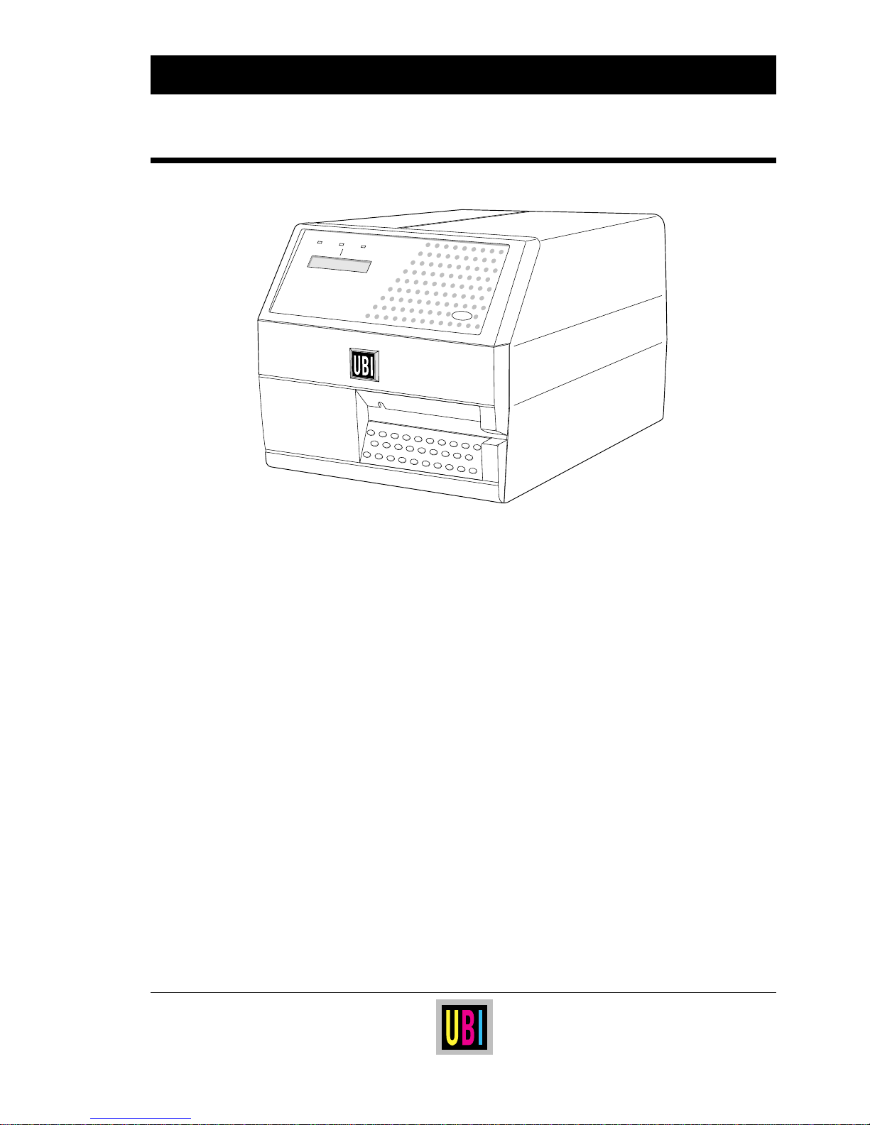
The UBI EasyCoder 401 Linerless Tear-Off (LLT) is a rugged direct thermal printer
intended for printing on pre-perforated linerless paper strip, from which labels can be
manually torn off.
Linerless paper eliminates the liner (backing paper), that usually protects the adhesive
on labels, and is thus more economical with about 60% more labels per roll. This gives
fewer paper reloads and the environment benefits from less waste.
Thanks to a special top coating, linerless paper has higher resistance against chemicals,
scratching and UV light and gives a darker image with longer life than common direct
thermal labels with liner.
The EasyCoder 401 LLT is fitted with the UBI Fingerprint firmware, which is
compatible with the UBI LabelShop label-editing program and the UBI Direct
Protocol. The flexible UBI Fingerprint programming language also allows you to
create your own programs.
Optionally, the EasyCoder 401 LLT can be fitted with a scalable fonts kit that allows
the use of outline fonts in Speedo and TrueType format, a label-taken sensor, and a realtime clock circuit. It can also be upgraded to an EasyCoder 401 LLC by fitting a
linerless paper cutter.
Power
Ready
Error
EasyCoder 401
Print
Page 6
6
UBI EasyCoder 401 Linerless – Technical Manual
Feature EasyCoder 401 Linerless Tear-Off Notes
Print Technique Direct Thermal on Linerless Media
Quick-Mount Printhead 8 dots/mm (203.2 dpi) Thin-film technique
Print Width max. 104 mm (4.09")
Media Width max. 114 mm (4.49")
Print Length max. 1250 mm (49.2")
Print Speed max. 100 mm/sec. (4"/sec.)
Fonts, expandible 4 times Standard: 10 Bitmapped
1
Min. 1 Bitmapped
Smooth Fonts Yes, with UBI Toolbox or Scalable Fonts Kit
2
Print Directions for Text, Images, Lines, and Boxes 4
Bar Code Generators Depends on software version
1
Internal Paper Roll Diameter max. 152 mm (6.0")
Keyboard, built-in Print key only
Display 2 lines x 16 characters LCD
Dimensions (W x D x H) 275 x 382 x 239 mm (10.8 x 15 x 9.4")
Weight (excl. paper and options) 14.0 kgs (31 lbs)
Ambient Operating Temperature + 5˚C – +40˚C (+41˚F – +104˚F) Applies to printer –not to media
Humidity 20–80% non-condensing Applies to printer –not to media
Sound Emission Level < 60 dB (A)
Microprocessor 32 bit
Programming Language UBI Fingerprint 6.1 or later Incl. UBI Direct Protocol
Startup program UBI Shell Standard 4.0 or later
On-Board RAM Memory, standard 256 kbytes Max. 512 kbytes
2
Paper End Sensor Standard
Mains Voltage 115/230 VAC +10/-15%, 2.6/1.3 A 60/50 Hz Selected by means of a switch
Max. Power Consumption 300 W
Communication Interface, standard RS 232C Prepared for RS 422/20 mA CL
1 x Centronics Interface
2
Optional On separate interface board
RS 232C Cable
2
Optional
Centronics Cable
2
Optional
Label-Taken Sensor (LTS)
2
Optional Not in combination with a cutter
Real-Time Clock Circuit
2
Optional
External RS 232C Alphanumeric keyboard
2
Optional
Paper Cutter Unit
2, 3
Optional Special Linerless Cutter w. LTS
Paper Roll Retainer
2
Optional
Scalable Fonts Kit
2
Optional Scales Speedo and TrueType fonts
UBI Toolbox, PC Windows configuration support
2
Optional
UBI LabelShop, WYSIWYG Label Software for Windows
2
Optional UBI LabelShop 3.2 or later
1
/. See UBI Fingerprint manuals
2
/. Options to be installed by user or reseller
3
/. If a cutter is fitted on an EasyCoder 401 LLT, it becomes an EasyCoder 401 LLC, see the two following pages.
MODELS, cont'd. EasyCoder 401 LLT
Page 7
7
UBI EasyCoder 401 Linerless – Technical Manual
MODELS, cont'd. EasyCoder 401 LLC
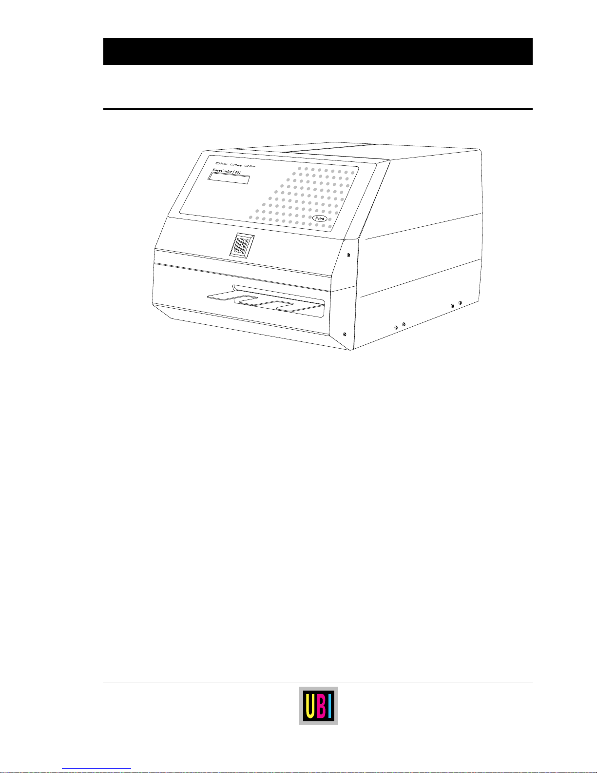
The UBI EasyCoder 401 Linerless Cutter (LLC) is a rugged cutter-equipped direct
thermal printer intended for printing on continuous linerless strip, which is automatically cut into labels. The cutter is fitted with a built-in label-taken sensor, that holds the
printing of a new label until the previous one has been removed. The cutter can also be
fitted with a guide plate, that facilitates manual removal of the labels, and prevents cutoff labels to get stuck to the printer or workspace.
Linerless paper eliminates the liner (backing paper), that usually protects the adhesive
on labels, and is thus more economical with about 60% more labels per roll, which gives
fewer paper reloads. Variable label length allows for fewer label sizes in stock. The
environment also benefits from less waste.
Thanks to a special coating, linerless paper has higher resistance against chemicals,
scratching and UV light and gives a darker image with longer life than common direct
thermal labels with liner.
The EasyCoder 401 LLC is fitted with the UBI Fingerprint software, which is
compatible with the UBI LabelShop label-editing program and the UBI Direct
Protocol. The flexible UBI Fingerprint programming language also allows you to
create your own programs.
Optionally, the EasyCoder 401 LLC can be fitted with a scalable fonts kit, that allows
the use of outline fonts in Speedo and TrueType format, and a real-time clock circuit.
Page 8
8
UBI EasyCoder 401 Linerless – Technical Manual
MODELS, cont'd. EasyCoder 401 LLC
Feature EasyCoder 401 Linerless Cutter Notes
Print Technique Direct Thermal on Linerless Media
Quick-Mount Printhead 8 dots/mm (203.2 dpi) Thin-film technique
Print Width max. 104 mm (4.09")
Media Width max. 114 mm (4.49")
Print Length max. 1250 mm (49.2")
Print Speed max. 100 mm/sec. (4"/sec.)
Fonts, expandible 4 times Standard: 10 Bitmapped
1
Min. 1 Bitmapped
Smooth Fonts Yes, with UBI Toolbox or Scalable Fonts Kit
2
Print Directions for Text, Images, Lines, and Boxes 4
Bar Code Generators Depends on software version
1
Internal Paper Roll Diameter max. 152 mm (6.0")
Paper Cutter Unit Standard Special Linerless model w. LTS
Keyboard, built-in Print key only
Display 2 lines x 16 characters LCD
Dimensions (W x D x H) 275 x 440 x 239 mm (10.8 x 17.3 x 9.4") Depth includes guide plate
Weight (excl. paper and options) 15.0 kgs (33 lbs)
Ambient Operating Temperature + 5˚C – +40˚C (+41˚F – +104˚F) Applies to printer –not to media
Humidity 20–80% non-condensing Applies to printer –not to media
Sound Emission Level < 60 dB (A)
Microprocessor 32 bit
Programming Language UBI Fingerprint 6.1 or later Incl. UBI Direct Protocol
Startup program UBI Shell Standard 4.0 or later
On-Board RAM Memory, standard 256 kbytes Max. 512 kbytes
2
Paper End Sensor Standard
Mains Voltage 115/230 VAC +10/-15%, 2.6/1.3 A 60/50 Hz Selected by means of a switch
Max. Power Consumption 300 W
Communication Interface, standard RS 232C Prepared for RS 422/20 mA CL
1 x Centronics Interface
2
Optional On separate interface board
RS 232C Cable
2
Optional
Centronics Cable
2
Optional
Real-Time Clock Circuit
2
Optional
External RS 232C Alphanumeric keyboard
2
Optional
Paper Roll Retainer
2
Optional
Scalable Fonts Kit
2
Optional Scales Speedo and TrueType fonts
UBI Toolbox, PC Windows configuration support
2
Optional
UBI LabelShop, WYSIWYG Label Software for Windows
2
Optional UBI LabelShop 3.2 or later
1
/. See UBI Fingerprint manuals
2
/. Options to be installed by user or reseller
Page 9

9
UBI EasyCoder 401 Linerless – Technical Manual
Installation Check List
❑ Unpack the printer as described on next page.
❑ Standard printer:
If you have a standard EasyCoder 401 Linerless printer, go on
to next step.
Customized printer:
If you have a customized EasyCoder 401 Linerless printer,
check its CPU board and possible parallel interface board in
regard of interface circuits and straps as described in the chapters
“Electronics” and “Interfaces” at the end of this manual. Then
go on to next step.
❑ Connect the printer to a mains socket as described later on in this
chapter.
❑ Connect the printer to its host computer by means of a suitable
communication cable as described later in this chapter. (Refer to
the chapter “Interfaces” for more information on computer
connection and cable configurations).
❑ Load a supply of linerless paper as described in the User's
Manual. Be careful to adjust the position of the label stop sensor
so it will detect any black marks at the back of the paper web.
❑ Check that the printhead is lowered.
❑ In case of an EasyCoder 401 LLC, check that the cutter unit is
locked in closed position.
❑ Turn on the power.
❑ Proceed according to the chapter “Starting Up”.
INSTALLATION
Page 10
10
UBI EasyCoder 401 Linerless – Technical Manual
Before starting the installation, carefully examine the delivery for
possible damage or missing parts:
❑ Open the box and lift the printer, together with the foam-plastic
shock absorbers, out of the box.
❑ Remove the shock absorbers and check that the machine has not
been visibly damaged during the transportation. Keep the packing material until you are sure that the printer functions properly.
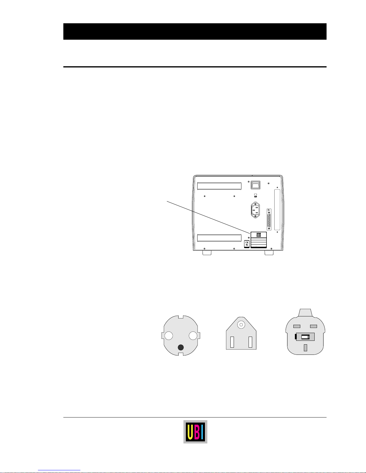
❑ The machine sign on the printer's rear plate gives information on:
• Type
• Article number
• Serial number
❑ Check the printer in regard to possible options ordered.
❑ In case of an EasyCoder 401 LLC printer, check that a separate
cutter guide plate is enclosed in the box. If so desired, install the
guide plate according to the enclosed installation instructions.
❑ Check that the mains cord has a pin configuration that will fit into
a wall socket according to the local standard.
Should any kind of damage have occurred during transportation,
immediately make a complaint to the carrier.
Any incorrect delivery or missing parts should be reported to the
distributor.
INSTALLATION, cont'd.
Unpacking
0
230V
MADE IN SWEDEN
Type
Art. No.
Ser. No.
115/230 V 2.6/1.3 A 50–60 Hz
TA
Machine Sign
European type US/Canadian type GB type
230V mains plug 115V mains plug 230V mains plug
Page 11
11
UBI EasyCoder 401 Linerless – Technical Manual
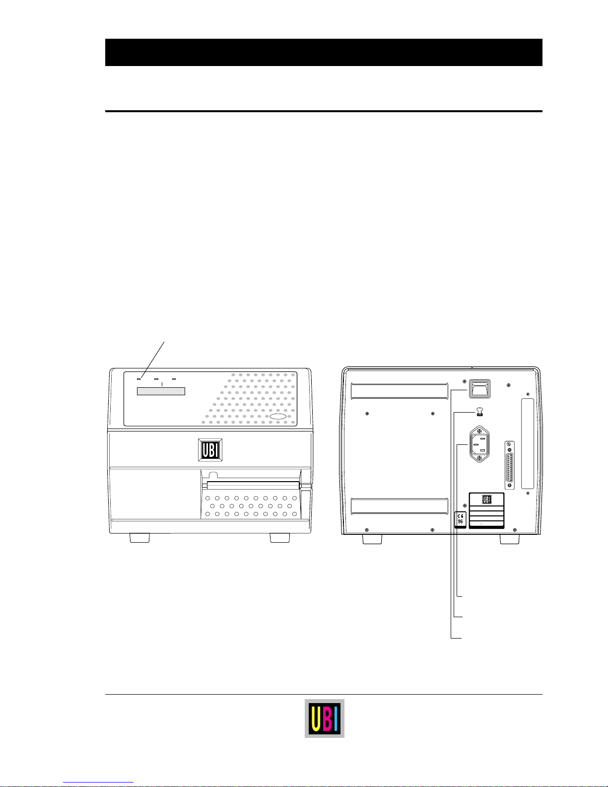
❑ Make sure that the printer is set for the correct voltage by
checking the voltage switch-over on the printer's rear plate.
❑ Fit the mains cord, which is included in the delivery, into the
mains receptacle. Connect the other end of the cord to a
grounded wall socket. To avoid interference from noise, surges
and spikes, a dedicated line is preferred. If no such line is
available, avoid lines to which electric motors, refrigerators and
similar devices are connected.
❑ The power can be turned on/off by means of the main switch
situated above the mains receptacle. The “Power” LED on the
printer's keyboard indicates when the power is on.
Mains Connection
INSTALLATION, cont'd.
0
230V
MADE IN SWEDEN
Type
Art. No.
Ser. No.
115/230 V 2.6/1.3 A 50–60 Hz
TA
Print
Power Ready Error
EasyCoder 401
Power On LED
Mains Receptacle
Voltage Switch-over
Main Switch
Page 12
12
UBI EasyCoder 401 Linerless – Technical Manual
INSTALLATION, cont'd.
Computer Connection
Hints:
• For UBI LabelShop, UBI Direct Protocol or UBI Fingerprint programming,
use the "uart1:" serial RS 232C communication channel.
• UBI's standard communication cables and adapters makes it possible to
connect the printer directly to the serial or parallel port of an IBM AT, XT or
PS-2 personal computer, or the serial port of an Apple Macintosh computer.
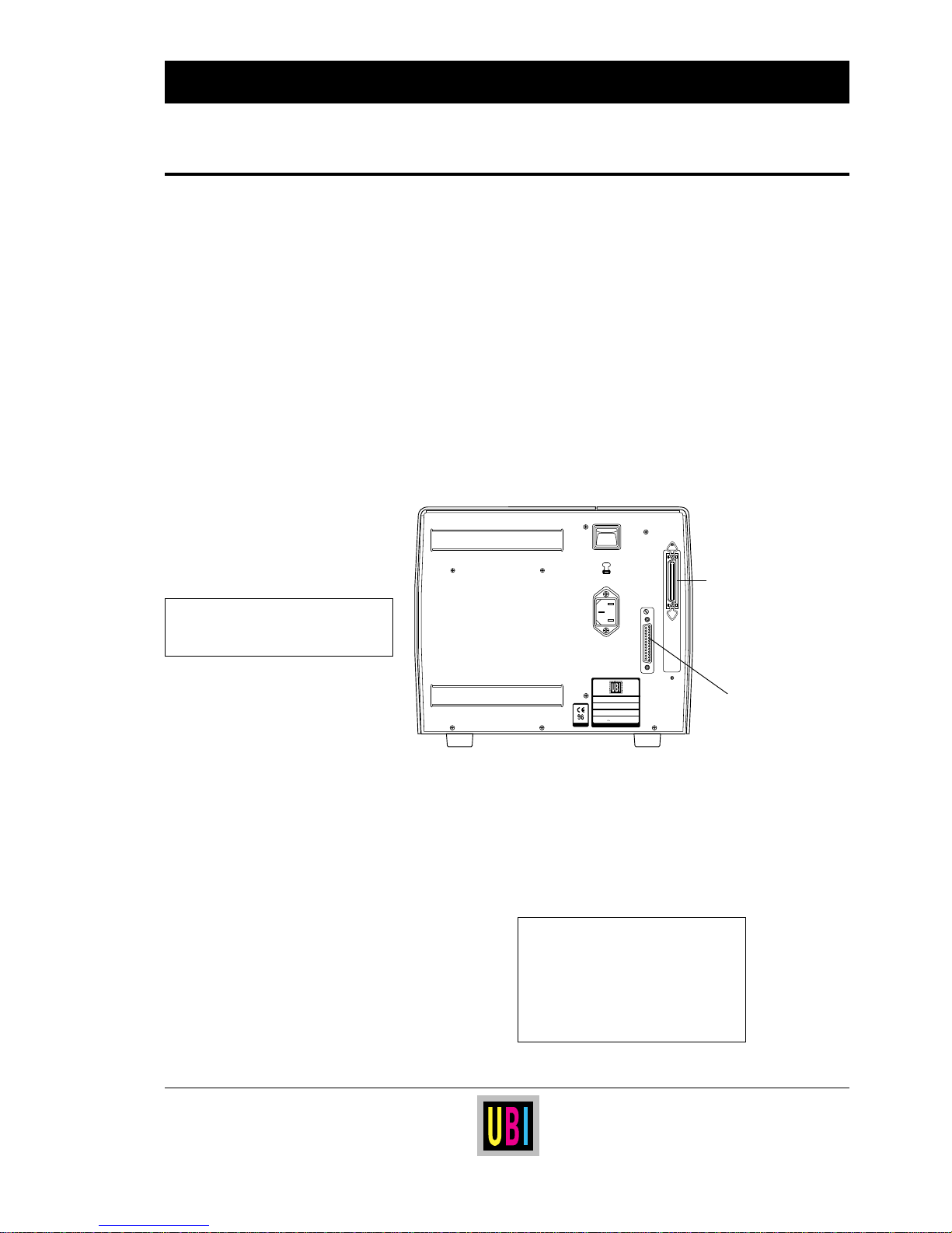
EasyCoder 401 Linerless is always fitted with one communication
port ("uart1:") for RS 232C on the rear plate.
As an option, this communication port can be reconfigured for
either RS 422 or 20 mA Current Loop after additional circuits have
been fitted on the CPU board, see chapter “Interfaces”.
The EasyCoder 401 Linerless can also be fitted with an optional
parallel interface board.
No communication cable is provided unless ordered separately.
Refer to the chapter “Interfaces” for cable configuration descriptions.
Refer to the manual of the host computer or terminal for information
on how to connect the other end of the communication cable.
230V
0
MADE IN SWEDEN
Type
Art. No.
Ser. No.
115/230 V 2.6/1.3 A 50–60 Hz
TA
Parallel Port
36-p female Centronics
(option)
Serial RS 232C Port
DB25 male
WARNING!
When connecting printer and host,
the power should be off!
UBI Standard Cables
RS 232C Cables:
Printer to IBM-AT 1-975581-05
Printer to IBM-XT/PS2 1-975580-05
Printer to Mac 1-010007-00
DB-25 Gender Changer 1-010008-00
Centronics Cable:
DB-25/Centronics 1-010001-00
Page 13
13
UBI EasyCoder 401 Linerless – Technical Manual
At startup, the behaviour of the printer is decided by the possible
existence of a startup (autoexec) file, i.e. a program that automatically starts running when the printer is turned on, somewhere in the
printer's memory. There are three major possibilities:
A The printer is fitted with the UBI Shell file-managing program,
which allows the operator to choose between a variety of
applications and functions.
B The printer is fitted with no startup file at all .
C The printer is fitted with a custom-made application program
that is design to perform a specific task, e.g. to print airline
tickets, baggage tags, or product labels for a certain company.
There can be one startup file stored in each of the following parts of
the printer's memory: RAM and ROM. If there are startup files
stored in more than one place, they will be used with the following
priority:
1. Printer's RAM memory.
2. Printer's ROM memory, e.g. the configuration EPROM's.
This implies that if you have a startup file stored in the configuration EPROM's and another in the printer's RAM memory
when you turn on the printer, the startup file in the RAM memory
will be used.
The display will keep you informed on what happens and in many
cases prompt you to take some kind of action, e.g. to choose
between options. How to take action depends on the startup
program.
Do not start the printer before you have made the necessary
connections, inserted any memory card you want to use, and
checked that the printhead is lowered and the optional cutter is in
closed position.
Turn on the power by means of the main switch on the rear plate.
The “Power” LED control lamp on the front panel lights up when
the power is on. Wait for a few moments, while the printer loads the
program and runs some self-diagnostic tests. Then some kind of
message will appear in the display window.
In case of a cutter-equipped printer, the cutter will perform a cutting
cycle at startup.
STARTING UP
Startup Files
EPROM = Erasable Programmable
Read-Only Memory
RAM = Random Access Memory
ROM = Read-Only Memory
Turning On the Printer
Page 14
14
UBI EasyCoder 401 Linerless – Technical Manual
STARTING UP, cont'd.
Messages at Startup
The type of startup file running in the printer is indicated by the
message shown in the display window directly after power up.
A. UBI Shell Startup Program (standard in EasyCoder 401 LL):
PRINT=UBI SHELL
5 sec. v.4.0
4 sec. v.4.0
3 sec. v.4.0
2 sec. v.4.0
1 sec. v.4.0
Refer to the UBI Shell Standard Startup Manual. The digits in the
lower right corner of the display indicate the version of UBI Shell.
B. No Startup File (non-standard EasyCoder 401 LL):
UBI Fingerprint
6.1
Refer to the documentation of the corresponding version of UBI
Fingerprint for further information.
C. Custom-made Application Program (non-standard EasyCoder 401 LL):
Any other display message than those illustrated above indicate that
the printer is running some custom-made, non-standard application
program or that some error has occurred.
Page 15
15
UBI EasyCoder 401 Linerless – Technical Manual
1
/. “Default” refers to the default setup values in the standard configuration EPROM's. A custom-made printer fitted with
non-standard configuration EPROM's may have a different combination of default setup values.
2
/. There is no communication setup and no receive and transmit buffers for the optional parallel communication channel.
3
/. All three options relate to the same nominal print speed.
4
/. Special Feedadjust, Media Type, and Paper Type setup values for EasyCoder 401 Linerless are stored in RAM before
delivery from factory and will have precedence over the standard default values stored in EPROM (same as those of the
non-linerless EasyCoder 401). In case of memory loss or memory reset, the values stored in RAM will be replaced by
those in EPROM. However, you can set up the printer again according to the default values in the table above or to your
own preferences, e.g. by means of UBI Shell. (For default paper type setup, enter “0100023122623” in “New Supplies”).
The setup allows you to adapt the printer for the desired type of
computer communication and to control the printing. The setup
parameters are:
General Information
Parameter Options Default
1
❑ Contrast Variable (0–10) Middle (5)
❑ Ser-Com2:
◆ Baudrate 300 | 600 | 1200 | 2400 | 4800 | 9600 | 19200 9600
◆ Parity even | odd | mark | space | none none
◆ Char length 7 bits | 8 bits 7 bits
◆ Stop bits 1 bit | 2 bits 2 bits
◆ Flow control:
- RTS/CTS Enable | disable disable
- ENQ/ACK Enable | disable disable
- XON/XOFF, data from host Enable | disable enable
- XON/XOFF, data to host Enable | disable enable
◆ New line CR/LF | LF | CR CR/LF
❑ Detection:
◆ LSS adjust Variable n.a.
◆ Feedadj4:
- Startadj Variable ± LLT: 0 LLC: -294
- Stopadj Variable ± LLT: 0 LLC: +250
❑ Service:
◆ Media size:
- X-start Variable (0 – 831) 0
- Width Variable (0 – 832) 832
- Length Unlimited 1200
◆ Media type4: [Label (w gaps)] | Ticket (w mark) | [Ticket (w gaps)] | LLT: Ticket (w mark)
Fix length strip | Var length strip LLC: Var length strip
◆ Print defs:
- Head resist Set automatically at startup n.a.
- Paper type
4
Select supply option. See chapter “Selecting Paper” 0100
- New supplies Select a new type of supply by means of a 13-digit code n.a.
- Testprint A series of test labels can be printed n.a.
◆ Performance3: Normal | High | Ultrahigh Normal
◆ Memory alloc:
- Image buff size Variable (max. 250 kbyte) 48 kbyte
- Rec buf size
2
Variable 300 byte
- Trans buf size
2
Variable 300 byte
SETUP PARAMETERS
Page 16

16
UBI EasyCoder 401 Linerless – Technical Manual
SETUP PARAMETERS, cont'd.
Continued!
This chapter explains the meaning of the various setup parameters.
There are several ways to change the setup:
• By means of the Terminal Setup option in UBI Shell, see the UBI
Shell Standard Startup Manual.
• By means of setup files or setup strings. See the UBI Fingerprint
Reference Manual,
SETUP statement, or the UBI Direct Protocol
Programmer's Guide.
The contrast setup allows you to make minor adjustment of the
printout in regard of blackness, e.g. to adapt the printer to variations
in quality between different batches of the same paper quality.
The serial communication setup controls the communication between the printer and the connected computer or other devices on
the standard serial channel "uart1:".
The serial communication setup has no consequence whatsoever
for parallel communication via an optional parallel interface
board.
For the serial communication channel, the following parameters
can be set. Make sure they match the setup of the connected device
or vice versa. The default setup (indicated by bold characters below)
is selected as to make the printer understand and act upon UBI
Fingerprint instructions transmitted from the host, regardless how
the host is set up. If the setup of the printer and the setup of the host
do not match, the response from the printer to host will be garbled.
• Baudrate:
The baudrate is the transmission speed in bits per second. The
following baudrates can be selected:
300
600
1200
2,400
4,800
9,600 Max. recommended baudrate for 20 mA current loop
19,200
If communication problems occur, try a lower baudrate.
Contrast
Serial Communication
• Baudrate
• Parity
• Character Length
• Stop Bits
• Flow Control
• New Line
Page 17

17
UBI EasyCoder 401 Linerless – Technical Manual
• Parity:
The parity decides how the software will check for transmission
errors. There are five options:
None
Even
Odd
Mark
Space
• Character Length:
The character length specifies the number of bits in a character.
For most purposes 7 bits will be sufficient, but if special characters
or characters specific for other languages are to be used, 8 bits are
recommended. Refer to the UBI Fingerprint Reference Manual
for information on which characters are available in various
combinations of character length and character set.
7 Characters ASCII 0 – 127 decimal can be transmitted.
8 Characters ASCII 0 – 255 decimal can be transmitted.
• Stop Bits:
The number of stop bits specifies how many bits will define the
end of a character. There are two options:
1
2
• Flowcontrol:
There are several different ways to control the exchange of data
between the printer and the connected computer or other device
(“Handshaking”). Each option can be enabled or disabled
separately, but normally only one alternative should be selected.
For galvanically insulated interfaces, i.e. 20 mA current loop and
RS 422, ENQ/ACK or XON/XOFF are to prefer in order to retain
interference protection and limit the number of lines.
• Flowcontrol, cont'd:
RTS/CTS
This is a protocol where the communication is controlled by currents through
separate lines in the cable being set either to high or low. By default, this option is
disabled.
RTS high indicates that the transmitting unit is able to receive characters. RTS low
indicates that the receive buffer is filled to 75% (see XON/XOFF).
CTS high indicates that the unit transmitting the CTS signal is ready to receive data.
CTS low indicates that the receive buffer is full (see XON/XOFF). In some computer
programs, e.g.
MS Windows Terminal
, RTS/CTS is designated “Hardware”.
SETUP PARAMETERS, cont'd.
Serial Communication,
cont'd.
Continued!
Page 18

18
UBI EasyCoder 401 Linerless – Technical Manual
DTR
DTR (“Data Terminal Ready”) is a signal, which is not controlled in the setup mode,
but by straps on the CPU board or interface board. DTR high indicates that the
transmitting unit is turned on.
ENQ/ACK
In this protocol, the communication is controlled by the special characters ENQ
(ASCII 05 dec.) and ACK (ASCII 06 dec.) being transmitted on the same line as the
data. The sending unit transmits ENQ at regular intervals. If the response ACK is not
received the transmission is held up awaiting an ACK character from the receiving
unit. By default, this option is disabled.
XON/XOFF
In this protocol, the communication is controlled by the special characters XON
(ASCII 17 dec.) and XOFF (ASCII 19 dec.) being transmitted on the same line as the
data. XON/XOFF can be enabled/disabled separately for data received from the
host by the printer (printer sends XON/XOFF), and for data transmitted to the host
from the printer (host sends XON/XOFF).
XOFF is sent from the printer when its receive buffer is filled by 75%, and the
transmission from the host is held up awaiting an XON character. When enough
data have been processed that the receive buffer is filled only to 50%, the printer
sends an XON character and the host resumes transmitting data. The same
principles apply to XON/XOFF sent by the host, even if the percentage may differ.
By default, XON/XOFF is enabled for data both ways.
• New Line:
This setup parameter allows you select the character(s) transmitted
from the printer to specify the switching to a new line. There are
three options:
CR/LF ASCII 13 dec. + ASCII 10 dec.
LF ASCII 10 dec.
CR ASCII 13 dec.
SETUP PARAMETERS, cont'd.
Serial Communication,
cont'd.
Page 19
19
UBI EasyCoder 401 Linerless – Technical Manual
SETUP PARAMETERS, cont'd.
The Detection facilities are used to adjust the label stop/black mark
sensor (LSS) and to control the paper feed.
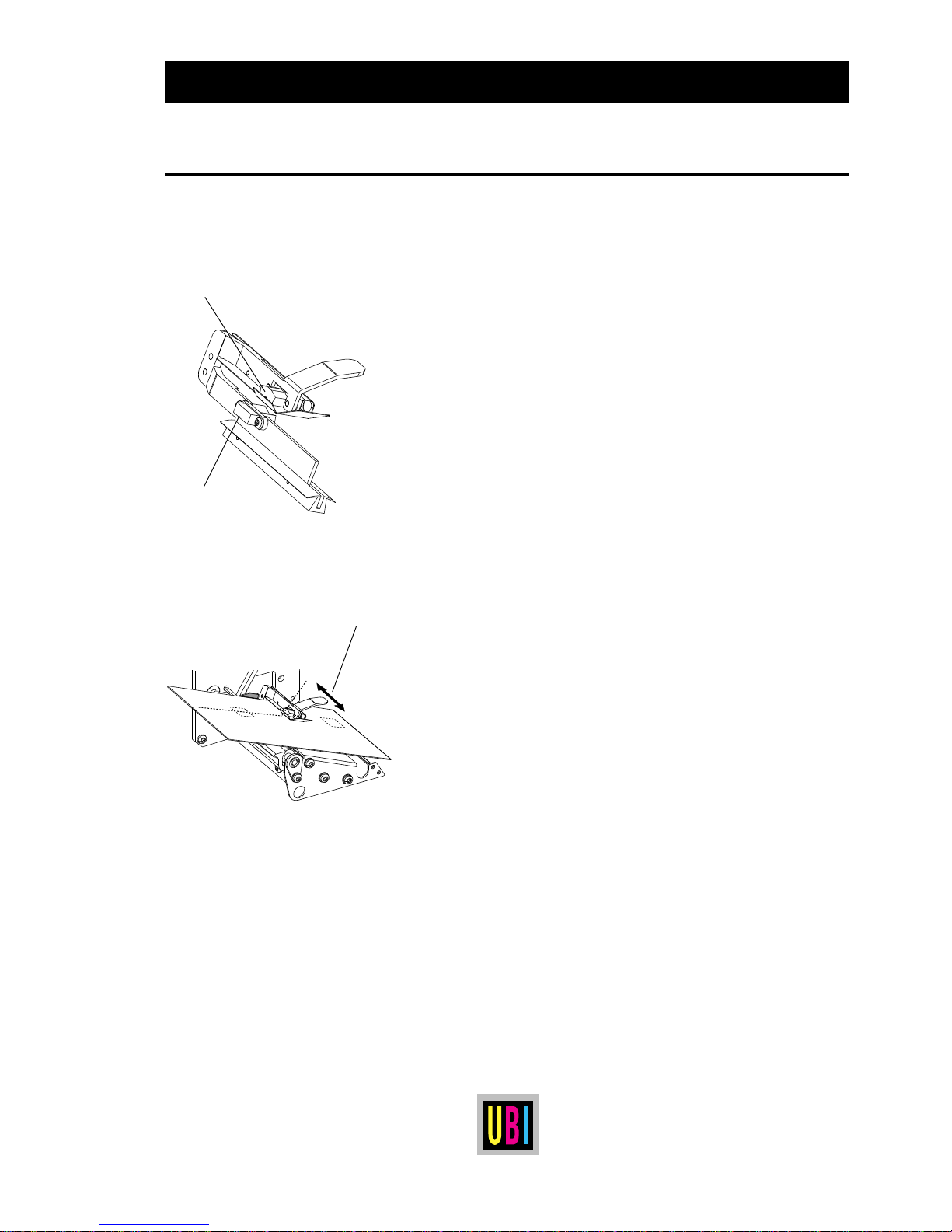
LSS Adjustment:
The LSS is a photo-electric detection device that controls the paper
feed. Situated inside the printing mechanism, it detects black marks
printed at the back of the paper web, or out of paper conditions.
When the printer is set up for “Ticket (w mark)”, the light is emitted
from the lower part of the LSS. The beam can be reflected back to
the receiver by the white paper at the back of the web, but if the beam
hits a black mark, practically no light will be reflected back. The
firmware is programmed to detect the rear edges of the black marks.
An out-of-paper condition is assumed, when no reflected light has
been detected within a feed length corresponding to the distance
between the dot line on the printhead and the sensor.
If the printer is set up for “Fix length strip”, or “Var. length strip”,
a narrow beam of light is emitted from the upper part of the LSS and
received by the sensor in the lower part. An out-of-paper condition
is assumed, when no interference to the beam has been detected
within a feed length corresponding to the distance between the dot
line on the printhead and the sensor.
The setup options “Label (w gaps)” and “Ticket (w gaps)” are not
used in connection with linerless paper.
Obviously, it is important that the printer is set up for the correct type
of media (see “Media Type” later in this chapter) so the firmware
can interpret the signals correctly.
The LSS can be moved max. 50 mm sideways from the inner edge
the web to detect black marks at various positions. The inner edge
of the handle indicates the lateral position of the sensor.
The LSS is automatically fine-adjusted when a Testfeed operation
is performed. Moreover, the LSS emitters can be adjusted in regard
of light intensity in the Setup Mode or by means of setup files, and
the LSS receiver can be adjusted by means of a potentiometer on the
CPU board (see the chapter “Electronics/Potentiometers”).
If the printer works as expected, there is no need to adjust the LSS,
but if the printer starts to feed out labels in an unexpected manner,
check that the sensor is properly aligned in relation to the web and
that it has not become dirty. Perform a few Testfeed operations to
allow the sensor to auto-adjust itself.
If the error remains, proceed according to the description of the
Setup Mode for the printer model in question. Only as a last resort
should the potentiometer be adjusted.
Continued!
Detection
• LSS Adjustment
• Feed Adjustment
Emitter and
Receiver
Emitter
The upper part of the LSS has a light
emitter to detect out of paper conditions,
whereas the lower part contains both a
receiver and an emitter for black mark
detection.
Handle
The inner edge of the handle indicates the
lateral position of the LSS.
Page 20
20
UBI EasyCoder 401 Linerless – Technical Manual
SETUP PARAMETERS, cont'd.
Feed Adjustment:
The Feed Adjustment contains two parameters, Start adjustment
and Stop adjustment, that will be effected regardless of which
program is run. Such global adjustments can be further modified for
various purposes by the use of
FORMFEEDs within the currently
running program.
The Start Adjustment is given as a positive or negative number of
dots:
•A positive start adjustment means that the specified length of
paper web will be fed out before the printing starts. Accordingly,
the origo is moved away from the forward edge of the copy. (This
has the same effect as a positive
FORMFEED before a PRINTFEED).
•A negative start adjustment means that the specified length of
paper web will be pulled back before the printing starts.
Accordingly, the origo is moved towards the forward edge of the
copy. (This has the same effect as a negative
FORMFEED before
a
PRINTFEED).
The Stop Adjustment is set up the same way.
•A positive stop adjustment means that the specified length of
paper web will be fed out after the printing is completed.
Accordingly, the origo is moved away from the forward edge of
next copy. (This has the same effect as a positive
FORMFEED after
a
PRINTFEED).
•A negative stop adjustment means that the specified length of
paper web will be pulled back after the printing is completed.
Accordingly, the origo is moved towards the forward edge of next
copy. (This has the same effect as a negative
FORMFEED after a
P
RINTFEED).
Notes:
In case of EasyCoder 401 LLC, keep in mind that this printer model
has a default Feed adjustment setup that is different from all other
EasyCoder printers. Since any
FORMFEEDs included in the pro-
gram will be supplement the Feed adjustment setup, running an
application program originally designed for other EasyCoders in
an EasyCoder 401 LLC may give unexpected results. In such cases,
change the Feed adjustment setup to 0/0 and see if it helps.
It is possible to turn off the label stop sensor for a certain amount
of paper feed, and to override the start adjustment and stop
adjustment setup by means of the
LBLCOND statement, see UBI
Fingerprint manuals.
Detection, cont'd.
TPH density 8 dots/mm (203.2 dpi):
1 dot = 0.125 mm = 4.92 mils
For more information on the instructions
FORMFEED and PRINTFEED, see UBI
Fingerprint Reference Manual or UBI
Direct Protocol Programmer's Guide.
Continued!
Page 21
21
UBI EasyCoder 401 Linerless – Technical Manual
The default setup values have been selected to allow the printer to
be operated as follows:
EasyCoder 401 LLT:
Start adjust: 0
Stop adjust: 0
Media type: Tickets (w marks)
If the black mark is printed so its rear edge is situated 2 mm behind
the perforation (in relation to the print direction), the paper can be
torn off at the perforation by means of the tear-off edge. About 15
mm (0.6") from the front edge of the copy will not be available for
printing. If printing from the front edge of the copy is desired, the
start adjust should be changed to a value of about -120.
If the black mark is posioned elsewhere, the start and stop adjust
values will have to be changed accordingly.
EasyCoder 401 LLC:
Start adjust: -294
Stop adjust: +250
Media type: Var. length strip
Each copy will get a start margin of approximately 1 mm (0.04")
and an end margin of approximately 4 mm (0.16"), where no
printing can be performed.
If the copies should be cut without such margins, change the setup
to approximately these values:
Start adjust -300
Stop adjust +235
Hints:
• It is possible to increase the cleaning interval by setting up the
printer, so the cut-off or torn-off edge of the paper never is pulled
back behind the front edge of the printhead profile. Else, adhesive
residue tend to build up on the profile and printhead, necessitating
more regular cleaning.
For this purpose, we recommend not to use start and stop adjust
values exceeding -50 (tear-off) or -250 (cut-off).
• In case of cut-off operation, we recommend to set up the printer
and design the programs so the following print cycle is obtained,
to ensure that the labels release properly from the pressing roller:
Backfeed ➙ Print ➙ Feed out ➙ Cut off
SETUP PARAMETERS, cont'd.
Detection, cont'd.
TPH density 8 dots/mm (203.2 dpi):
1 dot = 0.125 mm = 4.92 mils
Continued!
Notes:
The setup values listed in this chapter
are approximate values to be used
initially. Due to personal preferences,
differences between applications, and
minor mechanical differences between
individual printers, the values may need
to be fine-adjusted after testing.
In this chapter, positive values are
indicated by plus signs (+), but when
entering such values in the setup, the
plus signs should be omitted. However,
in case of negative values, leading minus
signs (-) must be included.
Page 22
22
UBI EasyCoder 401 Linerless – Technical Manual
SETUP PARAMETERS, cont'd.
X-start, Width and Length:
To protect the printhead from the potentially harmful condition of
printing outside the paper web, a printable area must be specified by
the use of the setup parameters X-start, Width and Length.
❑ X-start specifies the position of the origo along the dots on the
printhead. By default, X-start is set as 0, i.e. at dot No. 0 which
is the dot closest to the printer's centre-line wall.
Number of dots: 832
Outermost dot number: 831
Max. print width: 104 mm (≈ 4.1")
By setting a value larger than 0 for the X-start parameter, you will
move the origo outwards, away from the inner edge of the web.
In other words, the larger X-start value – the wider inner margin
and the less printable area.
❑ Width specifies the width of the printable area and is defined as
a number of dots from the origo. The sum of the X-start value and
the width value gives the outer margin of the printable area, as
illustrated on next page. The width must not be so large as to
allow printing outside the paper web.
❑ Length serves three purposes:
• To decide the length of the printable area from origo and along
the Y-coordinate as a number of dots.
• To decide the amount of paper feed when using “fix length
strip”.
• To set an “emergency stop”, which works when the printer is
set up for “Ticket (w mark)”. If the LSS has not detected a mark
within 150% of the set length, the paper feed is automatically
stopped to avoid feeding out a whole roll of paper, e.g. because
of a blocked or faulty LSS.
This implies that you can use labels or tickets longer than the
printable area:
Max. printable area (9999 dots): 1,250 mm (49.2")
Max. label or ticket length: 1,875 mm (73.8")
By setting up the X-start, the Width and the Length, you will
create a “print window” in which the printing can be performed.
Any object or field protruding outside the print window in any
direction will cause an error condition (Error 1003 “Field out of
label”) and the printing will be inhibited.
Continued!
Media Size
• X-start
• Width
• Length
Note!
It is important to change the width
setup whenever a narrow paper
is used. Never print outside the
paper web! That may cause damage to the printhead by overheating, since the paper serves as a
cooling media for the printhead
dots.
TPH density 8 dots/mm (203.2 dpi):
1 dot = 0.125 mm = 4.92 mils
Page 23
23
UBI EasyCoder 401 Linerless – Technical Manual
Print Window:
Printhead in left-hand position
Continued!
SETUP PARAMETERS, cont'd.
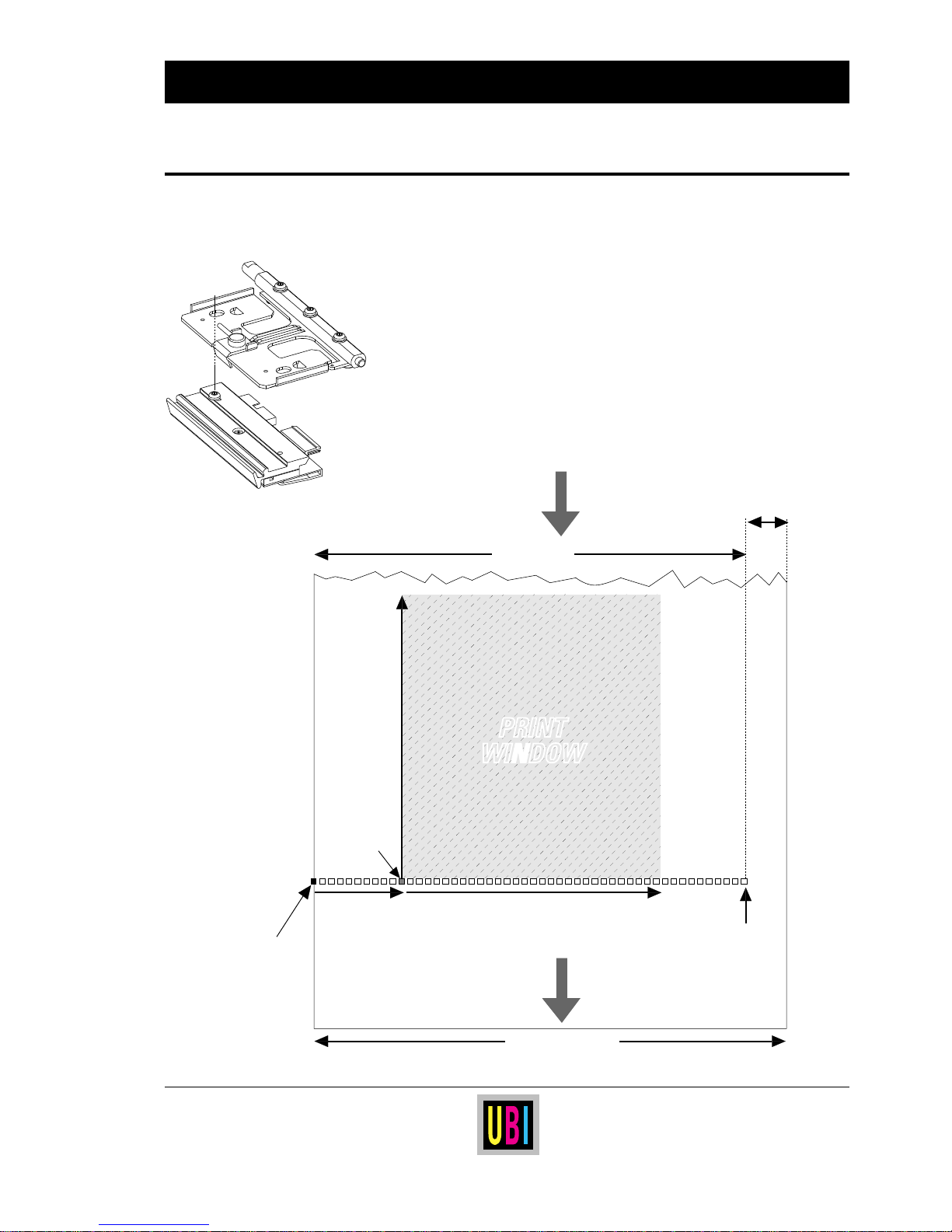
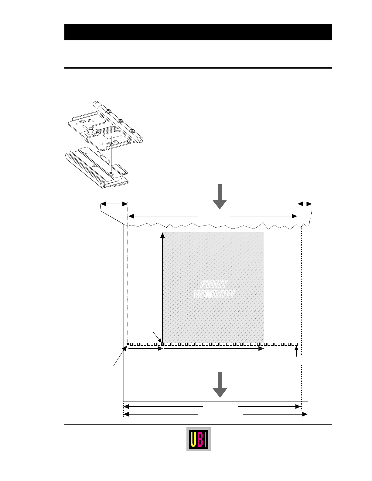
The printhead can be fitted in two positions (see chapter “Printhead
Replacement”). When the printhead is fitted in the innermost, left-
hand position (see illustration), dot No. 0 is aligned with the inner
edge of the paper web. Since the maximum print width is 104 mm
(4.1") and the maximum web width is 114 mm (4.49"), this leaves
a margin of at least 10 mm (0.39") along the outer edge of the web,
where no printing can be performed.
PAPER FEED
DIRECTION
Dot 0
Dot-line on
printhead
X-start Width
Origo
Length
From
paper supply
Dot 831
10 mm
(0.39")
PRINT
WINDOW
PRINT
WINDOW
max. 114 mm (4.49")
104 mm (4.1")
Page 24
24
UBI EasyCoder 401 Linerless – Technical Manual
Print Window:
Printhead in right-hand position
Continued!
SETUP PARAMETERS, cont'd.
The printhead can be fitted in two positions (see chapter “Printhead
Replacement”). When the printhead is fitted in the outer, right-hand
position (see illustration), dot No. 0 is situated 3 mm (0.12") inwards
from the inner edge of the paper web. Since the maximum print
width is 104 mm (4.1") and the maximum web width is 114 mm
(4.49"), this leaves a margin of at least 7 mm (0.28") along the outer
edge of the web, where no printing can be performed. Furthermore,
if an 110 mm (4.33") wide web is used, the printhead will be centrealigned with a 3 mm (0.12") wide margin.
Dot 0
X-start Width
Origo
Length
Dot 831
PRINT
WINDOW
PRINT
WINDOW
PAPER FEED
DIRECTION
Dot-line on
printhead
From
paper supply
7 mm
(0.28")
110 mm (4.33")
3 mm (0.12")
max. 114 mm (4.49")
104 mm (4.1")
Page 25

25
UBI EasyCoder 401 Linerless – Technical Manual
SETUP PARAMETERS, cont'd.
Media Type
The Media Type setup controls how the LSS and the paper feed
work. There are five standard media types, two of which are not
used in EasyCoder 401 Linerless printers:
❑ Label (w gaps) is used for adhesive labels mounted on backing
paper. This option is not intended for EasyCoder 401 Linerless.
■ Ticket (w mark) is used for pre-perforated paper strip provided
with black marks at the back of the paper web (EasyCoder 401
LLT only), or non-perforated paper strip with black marks
(EasyCoder 401 LLC only).
❑ Ticket (w gaps) is used for tickets and tags with detection slits.
This option is not intended for EasyCoder 401 Linerless.
■ Fix length strip is used for continuous paper strip without any
black marks or perforations in EasyCoder 401 LLC only. The
Length setup parameter (see Media Size) decides the length of
each copy.
■ Var length strip is used for continuous paper strip without any
black marks or perforations in EasyCoder 401 LLC only. The
length of each copy will be adapted to accommodate the print
image (including invisible parts like linefeeds or white parts of
an image) plus a small rear margin.
It is important to select the correct option, so the printer can indicate
possible paper errors. Two different error conditions may occur:
Error 1005 “Out of paper” indicates that the last ordered copy
could not be printed because of an empty paper stock.
Error 1031 “Next label not found” indicates that the last ordered
copy was successfully printed, but no more copies can be printed
because of an empty paper stock.
Head Resistance:
The power to the printhead is adjusted automatically according to
the printhead resistance each time the printer is started. There is no
manual head resistance setup.
Paper Type:
To obtain the best printout quality, the printer should be set up for
type of printing and the characteristics of the linerless direct thermal
paper quality currently used, see chapter “Selecting Paper”.
Print Defines
• Printhead Resistance
• Paper Type
• New Supplies
Continued!
Page 26

26
UBI EasyCoder 401 Linerless – Technical Manual
SETUP PARAMETERS, cont'd.
Performance
Memory Allocation
• Image Buffer
• Receive Buffer
• Transmit Buffer
New Supplies:
Other types of supplies, than those included as standard options in
the paper type setup, can be selected by means of a 13 digit code,
provided by the manufacturer or distributor. After a new supply has
been selected once by means of “New Supplies”, it will be stored
in the RAM memory and appear as an option in “Paper Type”,
specified by the first 4 digits in its code number.
Some special paper setup options for linerless paper are stored in the
printer's RAM memory. If the setup is lost, you will have to use the
New Supplies option to re-enter these options, using the 13 digit
codes listed in the chapter “Selecting Paper” later in this manual.
The Performance setup allows you to select the print speed. There
are three setup options:
• Normal
• High
• Ultra High
In EasyCoder 401 Linerless printers, all these three options trans-
late to the same nominal print speed, which is 100 mm/second (≈4"/
second) regardless of type of printing and print direction
1
.
The Memory Allocation setup allows you to set the size for three
memory buffers.
❑ The Image Buffer stores the printout image before printing and
during batch printing. To ensure that high print speed is sustained during the printing of demanding label formats, the size
of the Image Buffer may need to be increased. The maximum
size of the image buffer is 250 kbytes.
❑ The Receive Buffer stores the input data received on the serial
communication channel "uart1:" before processing.
❑ The Transmit Buffer stores the output data on the serial
communication channel "uart1:" before transmission.
1
/. Supplies, which have been specified by
means of the “New Supplies” option,
have separate fixed settings in regard of
print speed. Whenever such a supply is
selected, the “Performance” setup will
be of no consequence
Print Defines, cont'd.
Page 27

27
UBI EasyCoder 401 Linerless – Technical Manual
SETTING UP EASYCODER 401 LL
Different Methods The EasyCoder 401 Linerless is intended for applications, where
the printing will be controlled from a host computer and very little
action is required by the operator. Accordingly, there is only one
key available on the membrane keyboard on this type of printer.
The method of changing the setup depends on whether the printer
is fitted with some kind of startup file, a subject that was more
thoroughly discussed in the chapter Starting Up earlier in this
manual, to which the alphabetic references below refer.
A. EasyCoder 401 LL with UBI Shell:
• You can change any setup parameter via the Terminal Setup
option in UBI Shell.
• You can change the LSS setup via the Setup option of UBI Shell.
• As an alternative, you can also change the setup by means of a
setup file or setup string, see
SETUP in the UBI Fingerprint
Reference Manual or in the UBI Direct Protocol Programmer's
Guide.
B. EasyCoder 401 LL with no startup file installed:
• An EasyCoder 401 Linerless without any startup file can only be
set up by means of setup files or setup strings, see
SETUP in the
UBI Fingerprint Reference Manual or in the UBI Direct Protocol
Programmer's Guide.
C. EasyCoder 401 LL w. custom-made application program:
• Normally, necessary provisions for changing the setup should be
provided by the program by means of setup files or setup strings,
see
SETUP in the UBI Fingerprint Reference Manual or in the UBI
Direct Protocol Programmer's Guide.
Page 28

28
UBI EasyCoder 401 Linerless – Technical Manual
PRINTING PRINCIPLES
The printing is produced by the thermal printhead, which consists
of a line of very small, closely spaced resistors on a ceramic tile
fitted across the paper web. When a current is led through the
resistors, commonly called “dots,” these will be heated very
quickly. The heating is controlled by a powerful 32-bit microprocessor. When the current is shut off, the dots cool down just as fast.
As the paper is fed past the dots, the hot dots will produce a number
of black spots in the direct thermal paper. The spots can be
combined into patterns, which make up letters, bar codes or images.
The direct thermal printing method used in EasyCoder 401 Linerless
printers requires a special paper coated with a thin layer of heatsensitive chemicals. As the paper is fed past the dots, the heat from
the dots will make the chemicals react, producing a dark salt, which
makes up the imprint under each dot.
At printing, the thermal printhead must be pressed against the
pressing roller so the heat can be transferred to the thermal paper.
There must also be enough pressure to provide a sufficient amount
of friction between the paper and the pressing roller that drives the
paper. Too weak pressure gives a weak printout quality, whereas
too strong pressure may cause unnecessary wear of the printhead.
The pressure is factory adjusted, but special applications may
require readjustment using the trial-and-error method. Do not use
more pressure than necessary to obtain the desired printout quality.
General Information
Direct Thermal Printing
Printhead Pressure
Adjustment
Continued!
Page 29
29
UBI EasyCoder 401 Linerless – Technical Manual
Load
Print
+
-
Printhead Pressure
Adjustment, cont'd.
PRINTING PRINCIPLES, cont'd.
Continued!
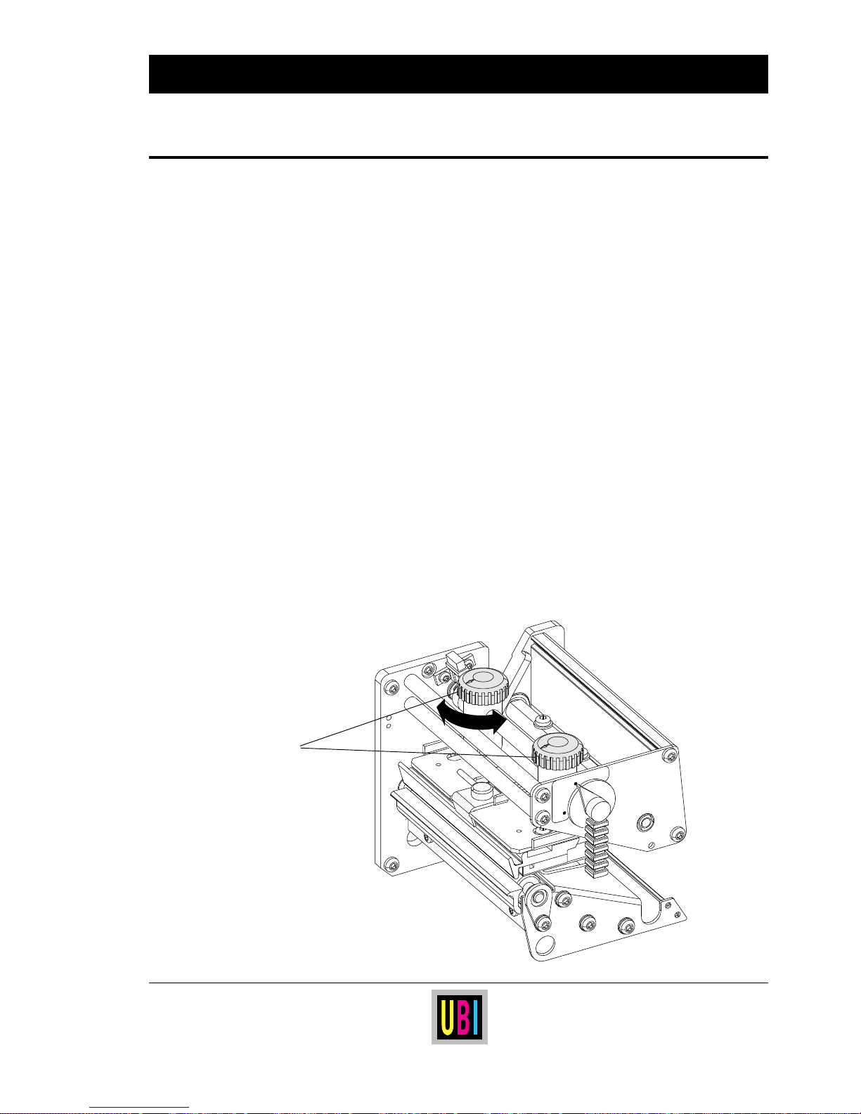
Adjustment Knobs
The print unit is fitted with two adjustable spring packages, which
allow the pressure to be set by turning the knobs:
• Turn the knobs clockwise to increase the pressure.
• Turn the knobs counter-clockwise to decrease the pressure.
At each quarter of a turn, the resistance increases and a clicking
sound can be heard.
The required pressure may vary between paper qualities of different
thickness. Generally, thicker face materials require more pressure
than thinner.
Make a rough adjustment like this:
• Turn both adjustment knobs clockwise as far as they go to
maximum pressure.
• Release the pressure of the inner spring package by turning the
knob 2
1
/4 turns counter-clockwise (9 clicks).
• Release the pressure of the outer spring package by turning the
knob 2 turns counter-clockwise (8 clicks).
Fine-adjust the pressure by turning the outer knob, while retaining
the setting of the inner knob. If the desired result cannot be obtained,
increase or decrease the pressure by turning both knobs a quarter of
a turn in the same direction, then fine-adjust the outer knob.
Page 30
30
UBI EasyCoder 401 Linerless – Technical Manual
PRINTING PRINCIPLES, cont'd.
Dot Size
The basis for all measures and positioning in the UBI Fingerprint
programming language is the size of printhead dots. For example,
in an 8 dots/mm printhead, each dot has a nominal size of 0.125 mm
(4.9 mils). This means that a heated dot under standardized conditions will produce a black spot which has a diameter of 0.125 mm.
Depending on dot temperature, exposure time, paper characteristics etc., the spot may actually be somewhat smaller (weak print) or
larger (black print), but that does not affect the calculation of
distances, sizes and positions.
The 8 dots/mm (203.2 dpi) printhead contains 832 dots, which gives
a maximum print width of 104 mm (4.095").
The same unit of measure (dots) can be used both across and along
the paper feed direction.
Density: 8 dots/mm (203.2 dpi)
Dot size (mm): 0.125
Dot size (mils): 4.92
Dot size (inches): 0.00492
1 mm: 8 dots
1 inch: 203.2 dots
1/16 inch: 12.7 dots
Conversion Table
Page 31
31
UBI EasyCoder 401 Linerless – Technical Manual
LINERLESS DIRECT THERMAL PAPER
The EasyCoder 401 Linerless printer models are intended for
linerless printing only. Normal direct thermal papers may be used,
but have to be tested in your application.
Linerless label web is provided with an adhesive layer at the back
of the web, which is not protected by any liner (backing paper), just
like a roll of self-adhesive tape. The metallic parts of the printer in
contact with the adhesive are treated with a special coating intended
to prevent the paper to stick to the metal, and the pressing roller has
a special surface for the same purpose. The face side of the label web
is provided with a thin silicon coating, that makes it easier to release
the web from the roll, and provides additional protection to the
printout against mechanical abrasion, moisture, chemicals, and
UV-light.
The characteristics of linerless labels make them less suited for the
printing of ladder-style bar codes, i.e. bar codes where the bars run
across the paper web. For best readability (ANSI A, CEN 4), use
picket fence bar codes only, i.e. bar codes with the bars running
along the paper web.
Linerless printing requires regular cleaning to avoid build-up of
adhesive residue in the print mechanism and the paper cutter. The
following cleaning intervals are recommended:
• Clean the printhead before loading each new roll of paper.
• Check all parts exposed to the adhesive after each 3 km of paper
feed (corresponds approximately to 20 full size paper rolls), and
clean if necessary.
• Clean the cutter at an interval of 50,000 cuts.
Follow the cleaning instructions in the User's Manual for best
printout quality and troublefree performance.
Linerless label materials are available in normal and thin calipers
with normal or high sensitivity. Both permanent and removable
adhesives are available.
UBI
offer stock label rolls for direct thermal linerless printing
in a variety of widths and qualities.
Special sizes and qualities can be offered on request.
Please contact your
UBI
distributor or
UBI
Sales Office.
General Information
Page 32
32
UBI EasyCoder 401 Linerless – Technical Manual
SELECTING PAPER
Setup Options
1
/. If the desired printout quality is not
obtained using the default setup 0100, try
these options to find the one that best suits
your label layout.
The printer can be set for various types of direct thermal papers by
means of the setup parameter “Paper Type”.
The printer's firmware contains a number of standard thermal paper
options stored in EPROM, as listed below. Most of them are
intended for non-linerless direct thermal paper only (refer to the
UBI EasyCoder 401 Technical Manual), but a few can also be used
for linerless printing. To achieve better print quality, the printer is
also provided with some specific linerless “Paper Type” options,
which are stored in RAM at factory using the “New Supplies”
option.
The “New Supplies” setup parameter allows additional options to
be selected by entering a 13-digit code. Once selected, such an
option can be reselected as a “Paper Type” option using the first 4
digits of its code number. The “New Supplies” option is also used
to re-enter linerless paper setup options if the setup accidently has
been lost.
STANDARD SETUP OPTIONS (stored in EPROM)
Option Application Note
KANZAKI 86S
Non-linerless printing
RICOH 130LAB/LAM
Non-linerless printing
UBI DT 110 Specific applications
1
Also non-linerless DT paper
UBI DT 110 + Specific applications
1
Also non-linerless DT paper
UBI DT 110 ++ Specific applications
1
Also non-linerless DT paper
UBI DT 120 Specific applications
1
Also non-linerless DT paper
SPECIAL SETUP OPTIONS (stored in RAM)
Option Application New Supplies code
0100 Std. UBI Linerless labels 0100023122623
0101 Specific applications10101023122442
Page 33
33
UBI EasyCoder 401 Linerless – Technical Manual
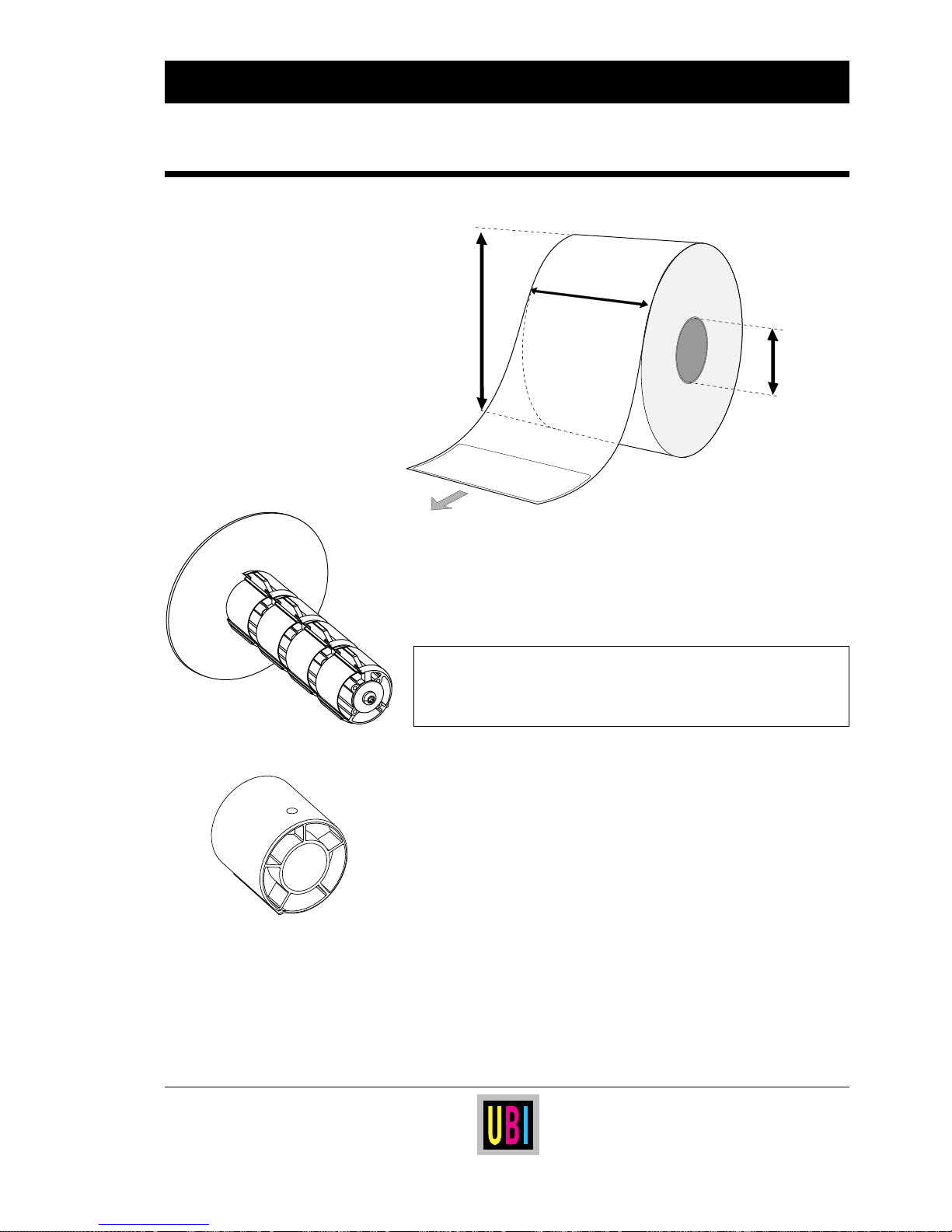
Roll Size
PAPER DIMENSIONS
Bobbin (Ø 38 mm/1.5")
1
/. 175µm is the recommended maximum thickness. Thicker web may be used at
the possible expense of an impaired printout quality. However, the stiffness is
also important. A stiff web limits the maximum thickness and vice versa.
Adapter (Ø 76 mm/3")
Core:
Diameter w/o adapter .. : 38–40 mm (1.5–1.6")
Diameter w. adapter .... : 7 6 m m (3")
Width .........................: Must not protrude outside the web .
Warning!
The paper must be attached the core in such a manner
that the printer can pull the end of the paper
free from the core.
Roll:
Max. diameter.............: 152.0 mm (6.00")
Max. width .................: 114.0 mm (4.49")
Min. width (tear-off) ...: 25.4 mm (1.0")
Min width (cut-off) ..... : 50.8 mm (2.0")
Max. web thickness
1
.......
: 175 µm (0.007")
Web width:
Max. 114.0 mm ( 4.49")
Min. 25.4 mm (1.0") Tear off
Min. 50.8 mm (2.0") Cutter
Printable
side
or
labels
Core diameter:
38 - 40 mm (1.5" - 1.6")
or
76.2 mm (3")
Roll diameter:
max. 152 mm (6")
Page 34
34
UBI EasyCoder 401 Linerless – Technical Manual
PAPER DIMENSIONS, cont'd.
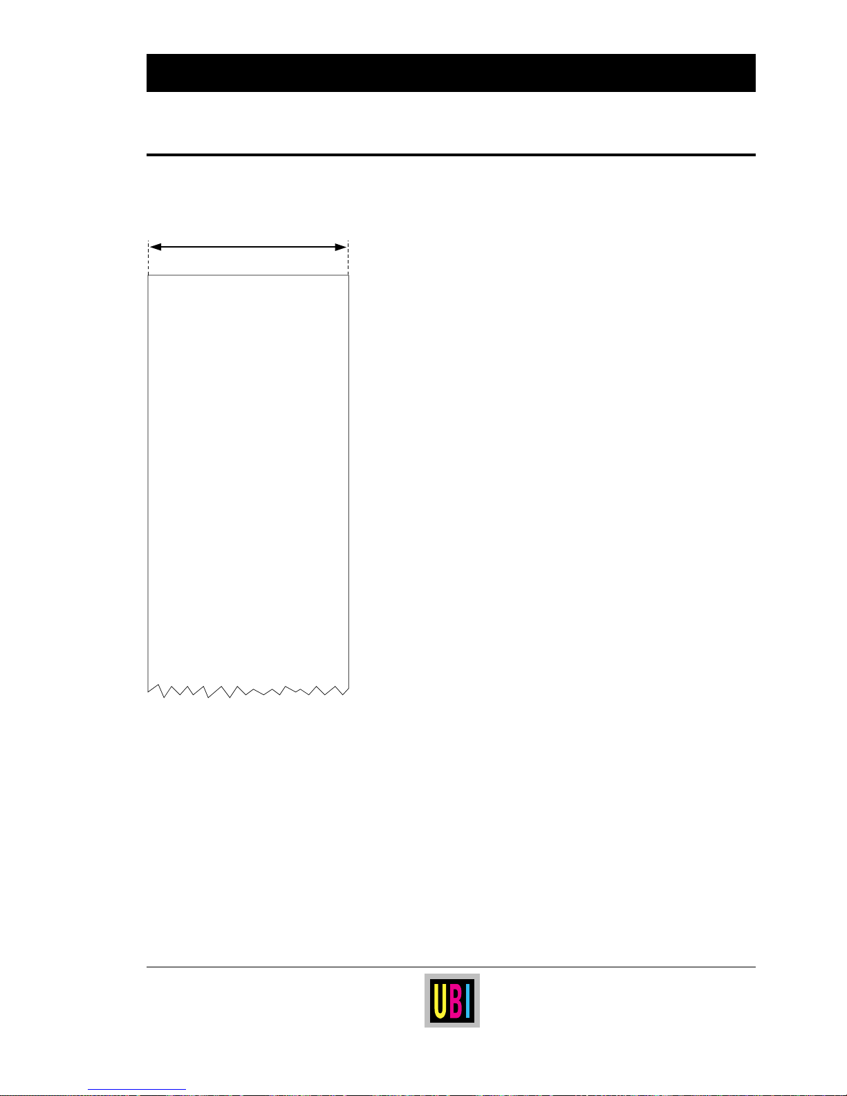
Intended for EasyCoder 401 LLC.
Use setup options:
• Variable Length Strip (default), or
• Fixed length strip
← a → Paper Width
Maximum ....................................................... : 114.0 mm (4.49")
Minimum ....................................................... : 50.8 mm (2.00")
Copy Length:
Max. length1.................................................... : 1875 mm (73.8")
Min. length ...................................................... : 38.1 mm (1.5")
Max. printable length....................................... : 1250 mm (49.2")
Linerless Strip w/o Marks
a
LINERLESS STRIP
NO BLACK MARKS
NO PERFORATION
1
/. The last third of a ticket or tag with
maximum length cannot be used for
printing! Also see “Max. printable
length”.
Page 35
35
UBI EasyCoder 401 Linerless – Technical Manual
PAPER DIMENSIONS, cont'd.
1
/. The last third of a ticket or tag with
maximum length cannot be used for
printing! Also see “Max. printable
length”.
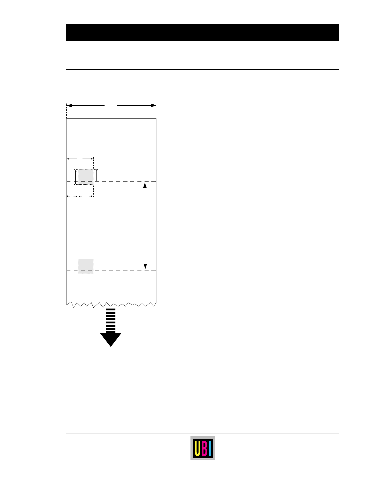
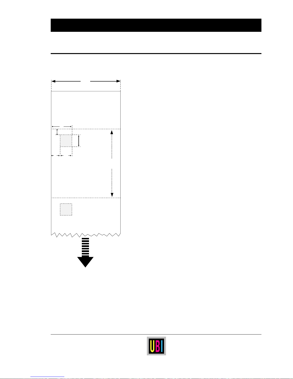
Perforated Strip w. Marks Perforated strip with marks is intended for EasyCoder 401 LLT.
Use setup option:
• Ticket (w mark)
← a → Web Width:
Maximum ........................................................ : 114.0 mm (4.49")
Minimum ........................................................ : 25.4 mm (1.0")
← b → Copy Length:
Max. length1.................................................... : 1875 mm (73.8")
Min. length ...................................................... : 25.4 mm (1.0")
Max. printable length....................................... : 1250 mm (49.2")
The length should exceed the width.
← c → Black Mark Offset:
Max. offset ...................................................... : 40 mm (1.57")
Min. offset .......................................................: 0 mm (0.0")
← d → Detectable Width of Black Mark:
Minimum ........................................................ : 10 mm (0.4")
← e → Black Mark End:
No restriction, but the LSS cannot detect the mark more than 50 mm (1.97") from
the inner edge of the paper.
← f → Black Mark Height:
Commonly used height ....................................: 12.5 mm (0.5")
Minimum ........................................................ : 5.0 mm (0.2")
← g → Black Mark/Perforation Offset:
The rear edge of the black mark should come 4 mm (0.16") behind the
perforation (as seen in relation to the print direction).
Perforation:
It is recommended not to allow possible perforation to break the edges of the
web. Else there is a small risk that the web may be partly separated before
printing, causing a paper jam.
Important!
Preprint that may interfere with the detection of the black mark should be
avoided on the back of the paper. However, the LBLCOND instruction allows the
sensor to be temporarily disabled during a certain amount of paper feed in order
to avoid unintentional detection, see UBI Fingerprint manuals.
The mark should be non-reflective carbon black on a whitish background.
a
LINERLESS STRIP
BLACK MARKS &
PERFORATION
e
PAPER FEED
DIRECTION
f
dc
g
b
Page 36
36
UBI EasyCoder 401 Linerless – Technical Manual
PAPER DIMENSIONS, cont'd.
1
/. The last third of a ticket or tag with
maximum length cannot be used for
printing! Also see “Max. printable
length”.
Non-Perforated Strip w. Marks
a
LINERLESS STRIP
W. BLACK MARKS
NO PERFORATION
e
PAPER FEED
DIRECTION
f
g
dc
b
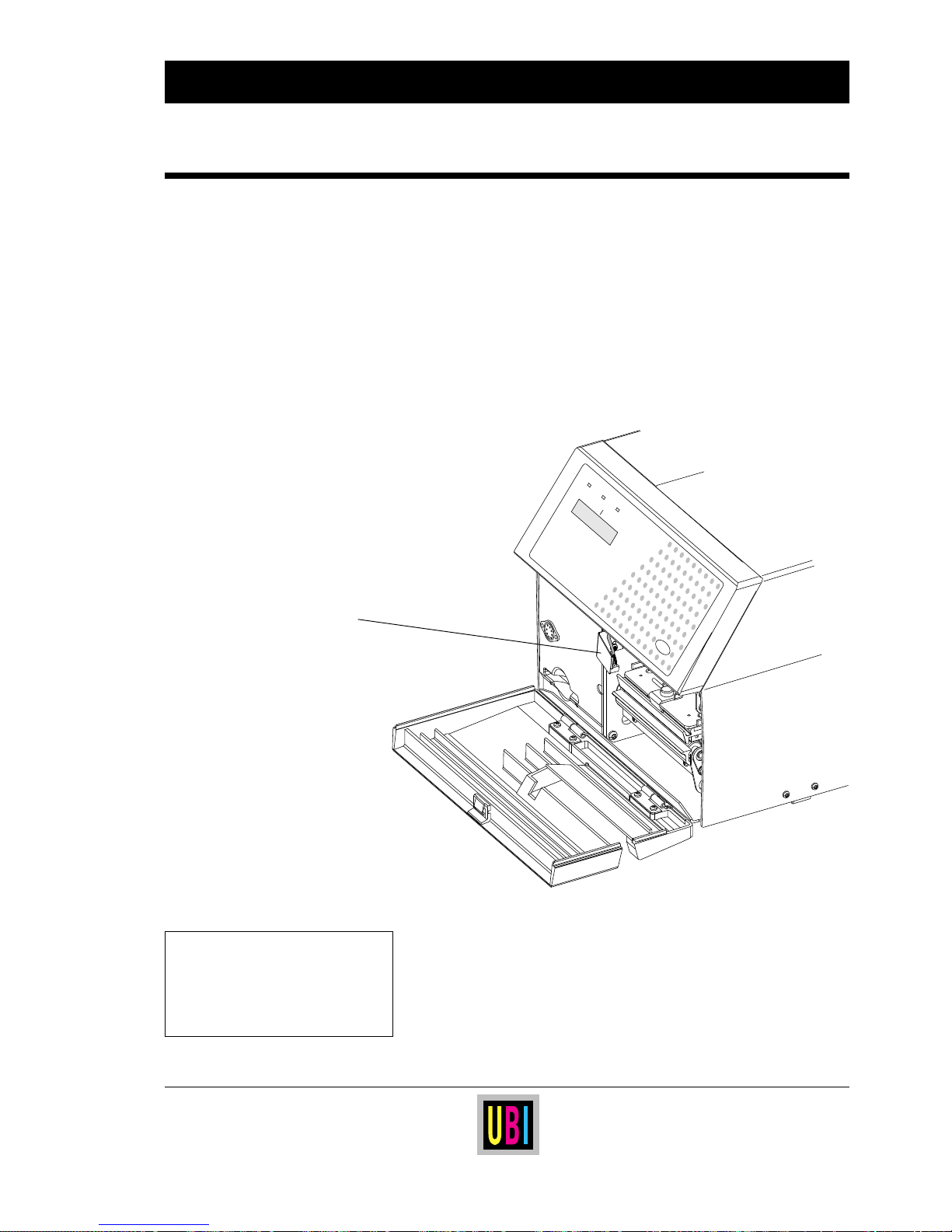
Non-perforated strip with marks is intended for EasyCoder 401 LLC.
Use setup option:
• Ticket (w mark)
← a → Web Width:
Maximum ........................................................ : 114.0 mm (4.49")
Minimum ........................................................ : 50.8 mm (2.0")
← b → Copy Length:
Max. length1.................................................... : 1875 mm (73.8")
Min. length ...................................................... : 38.1 mm (1.5")
Max. printable length....................................... : 1250 mm (49.2")
← c → Black Mark Offset:
Max. offset ...................................................... : 40 mm (1.57")
Min. offset .......................................................: 0 mm (0.0")
← d → Detectable Width of Black Mark:
Minimum ........................................................ : 10 mm (0.4")
← e → Black Mark End:
No restriction, but the LSS cannot detect the mark more than 50 mm (1.97") from
the inner edge of the paper.
← f → Black Mark Height:
Commonly used height ....................................: 12.5 mm (0.5")
Minimum ........................................................ : 5.0 mm (0.2")
← g → Cut Position:
When the default feed adjustment setup is used, the cutting will occur approx.
7 mm (0.28") after the rear of each black mark (as seen in relation to the print
direction).
Important!
Preprint that may interfere with the detection of the black mark should be
avoided on the back of the paper. However, the LBLCOND instruction allows the
sensor to be temporarily disabled during a certain amount of paper feed in order
to avoid unintentional detection, see UBI Fingerprint manuals.
The mark should be non-reflective carbon black on a whitish background.
✃
✃
Page 37
37
UBI EasyCoder 401 Linerless – Technical Manual
The Label-Taken Sensor (LTS) is a device, which enables the
printer's software to detect if the latest printed label, ticket, tag etc.
has been removed before printing another copy.
The label-taken sensor is available i two cases:
• Fitted as standard in the cutter of all EasyCoder 401 LLC printers.
• As a kit for upgrading of EasyCoder 401 LLT printers
1
.
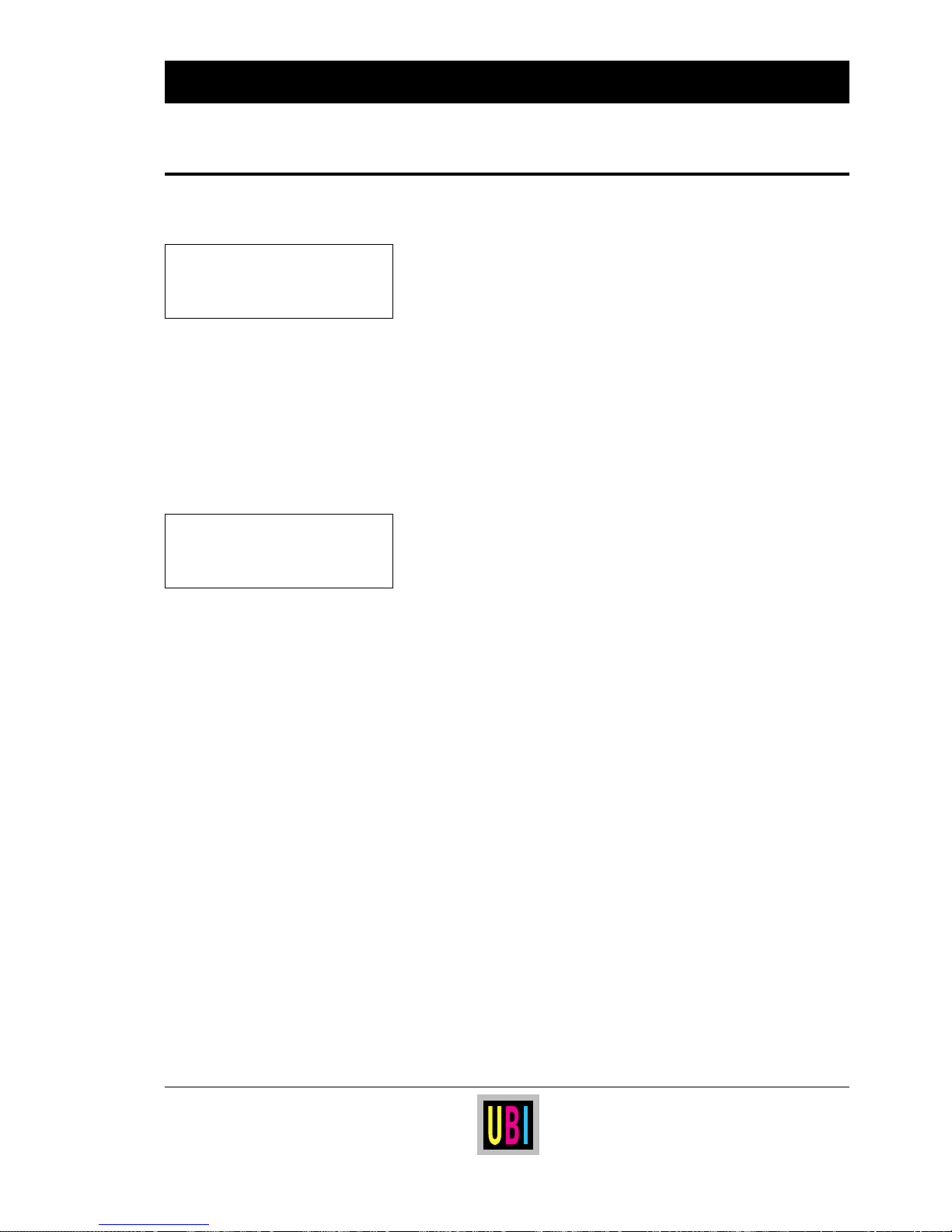
In the EasyCoder 401 LLT, the label-taken sensor consists of a
photoelectric sensor with a bracket and a connection cable. The
sensor is fitted inside the front door, see illustration below.
The photoelectric sensor emits a narrow beam of light, which will
be reflected back to the sensor by any label, ticket, tag, piece of strip
or backing paper, that has not been removed from the outfeed area.
A prerequisite is that the web is fed out along the inner wall of the
printer.
The sensitivity can be adjusted by means of a potentiometer, as
described on next page.
Continued!
General Information
LABEL-TAKEN SENSOR
Print
Power Ready Error
EasyCoder 401
Label-Taken Sensor
1
/. When field-installing an LTS in an
EasyCoder 401 LLT printer, the cable
fitted between P-606 on the CPU board
and the cutter interface connector must
be disconnected from the CPU board
and replaced by the cable from the LTS.
Page 38

38
UBI EasyCoder 401 Linerless – Technical Manual
LABEL-TAKEN SENSOR, cont'd.
❑ The sensitivity of the label-taken sensor can be adjusted by
means of a potentiometer situated on the CPU board, as described in the chapter “Electronics; Potentiometers” later in this
manual
1
.
CAUTION!
Since the adjustment must be performed with the power on, take
utmost care to avoid any risk of electrical shock or shortcircuits. Only use a non-conductive screwdriver and keep the
fingers away from the CPU board and the area behind it, where
the mains inlet and mains switch are situated.
❑ You can adjust the potentiometer randomly and check if it is
working properly by trying to print a label without removing the
previous one. Also check that you can print a label when there
is no label left under the LTS. Use the trial-and-error method
until the LTS works properly.
❑ Another way is to make a simple UBI Fingerprint program that
checks the printer's status using the
PRSTAT function (also see
UBI Fingerprint manuals). Here is an example on how such a
program can be made:
10 BREAK 1,88
20 BREAK 1 ON
30 ON BREAK 1 GOSUB 1000
40 FORMFEED
50 IF (PRSTAT AND 2) THEN BEEP
60 GOTO 50
70 END
1000 BREAK 1 OFF
1010 GOTO 70
RUN
You can break this program by transmitting the character X
(ASCII 88 decimal) on the standard interface "uart1:".
• Leave the label, ticket etc. in the outfeed slot.
• The sensor is properly adjusted when the printer beeps
continuously. Turn the potentiometer screw a quarter of a
turn in each direction. The beeping should not stop.
• Remove the label and the beeping should cease at once.
• If necessary, adjust the potentiometer until the label-taken
sensor works as described above.
• When adjusting the potentiometer, always create a safetymargin by turning the adjustment screw a quarter of a turn
further after the beeper has started or ceased to sound.
❑ Close the cover.
Adjusting the Sensitivity
Continued!
1
/. In an EasyCoder 401 LLT, the intensity
of the light emitted from the LTS can be
adjusted by means of a strap on P-607 on
the CPU Board:
No strap = weaker
Strap = stronger
In an EasyCoder 401 LLC, no strap must
be fitted on P-607.
NOTE!
This chapter also applies to the labeltaken sensor fitted inside the cutter of
the EasyCoder 401 LLC
Page 39
39
UBI EasyCoder 401 Linerless – Technical Manual
Program Example
LABEL-TAKEN SENSOR, cont'd.
The LTS can be enabled or disabled by means of the instructions
LTS& ON and LTS& OFF respectively (introduced with UBI Finger-
print 6.0 and the UBI Direct Protocol). Here is an example on how
the label-taken sensor is used to control the printing of a ten-label
batch printing job. A new copy will not be printed until the pending
label has been removed.
IMMEDIATE OFF
FONT "SW030RSN"
PRTXT "HELLO"
LTS& ON
PRINTFEED 10
The LTS fitted inside the cutter on an EasyCoder 401 LLC can be
used for detecting paper jams by means of a few lines in a UBI
Fingerprint program, as illustrated by the following example:
IMMEDIATE OFF
'Init
QJAMWAIT%=150 (see note)
OPTIMIZE "BATCH" ON
.....
'MAIN LOOP
W%=TICKS+QJAMWAIT%
PF
.....
WHILE (TICKS<W%) AND (NOT(PRSTAT AND 2))
.....
WEND
IF NOT (PRSTAT AND 2) THEN GOSUB JAMHANDLER
.....
JAMHANDLER:
BEEP
RETURN
Note:
If necessary, adjust value of QJAMWAIT% variable to obtain
proper jam detection.
NOTE!
This chapter also applies to the labeltaken sensor fitted inside the cutter of
the EasyCoder 401 LLC
Paper Jam Detection
in Cutter
NOTE!
This chapter only applies to the labeltaken sensor fitted inside the cutter of
the EasyCoder 401 LLC
Page 40
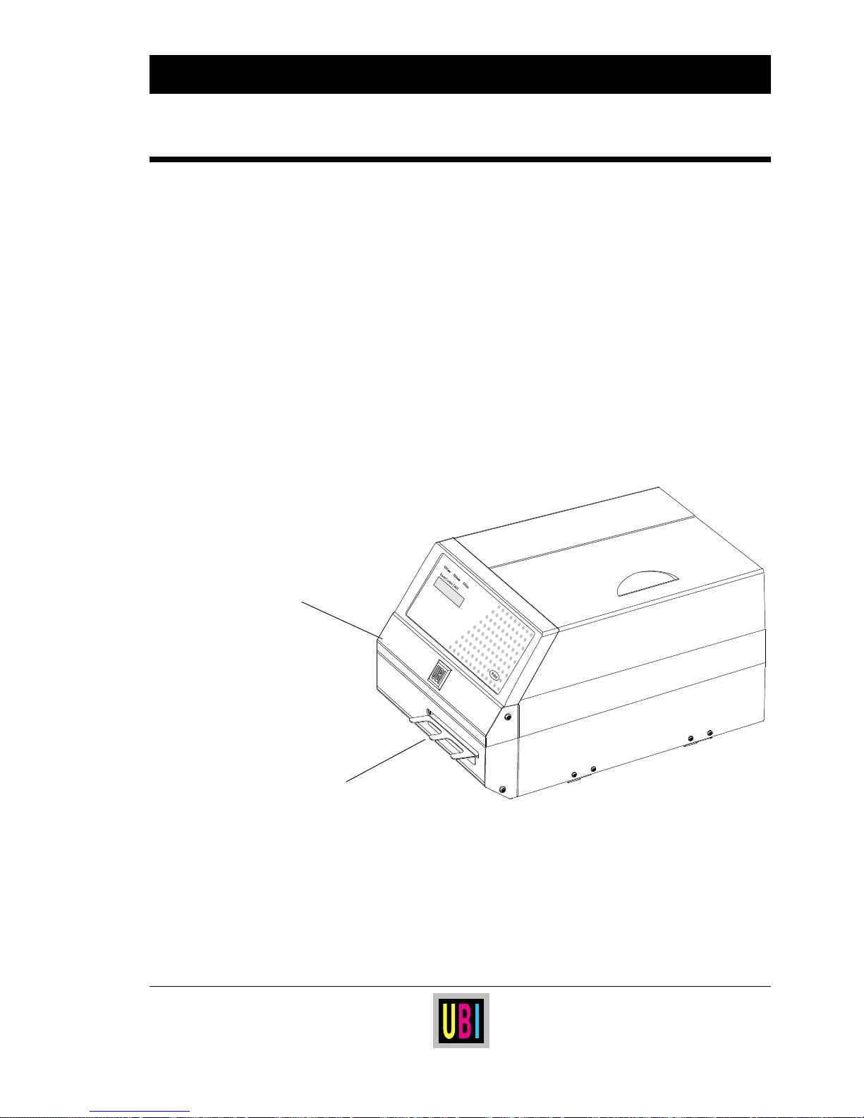
40
UBI EasyCoder 401 Linerless – Technical Manual
LINERLESS PAPER CUTTER
Continued!
General Information
EasyCoder 401 LLC is factory-fitted with a special Linerless Paper
Cutter, which is specially designed to cut through linerless paper.
EasyCoder 401 LLT can easily be fitted with the same cutter which
is available as a field-installable option
1
. The cutter unit is fitted on
the same hinges as the front door, which it replaces, and is connected
by a single cable to the DIN-connector on the printer's front.
The Linerless Paper Cutter is provided with a label-taken sensor at
the outfeed slot, which works the same way as the ordinary labeltaken sensor. A fork-shaped guide plate can be fitted at the outfeed
slot to avoid cut off labels to bend downward, which would prevent
them being detected by the label-taken sensor and to avoid labels
getting stuck to the printer or workspace. The guide plate is not fitted
at delivery, but is easily mounted using two #T10 Torx screws.
Using customized UBI Fingerprint programs, the cutter's labeltaken sensor can also be used to detect paper jams, see the chapter
“Label-Taken Sensor”.
Maximum thickness is 175 µm ( ≈ 175 grammes/m
2
) for paper-
based linerless materials.
The Linerless Paper Cutter increases the printer's total weight by
approx. 1.0 kgs (=2.2 lbs) and its length by 28 mm (1.1") without
guide plate and 58 mm (2.3") with guide plate.
Guide Plate
Cutter Unit
1
/. When fitting a cutter to an EasyCoder
401 LLT, any LTS already fitted must be
removed and the LTS potentiometer must
be adjusted according to the characteristics of the LTS in the cutter, as
described in the chapter “Label-Taken
Sensor”.
Page 41
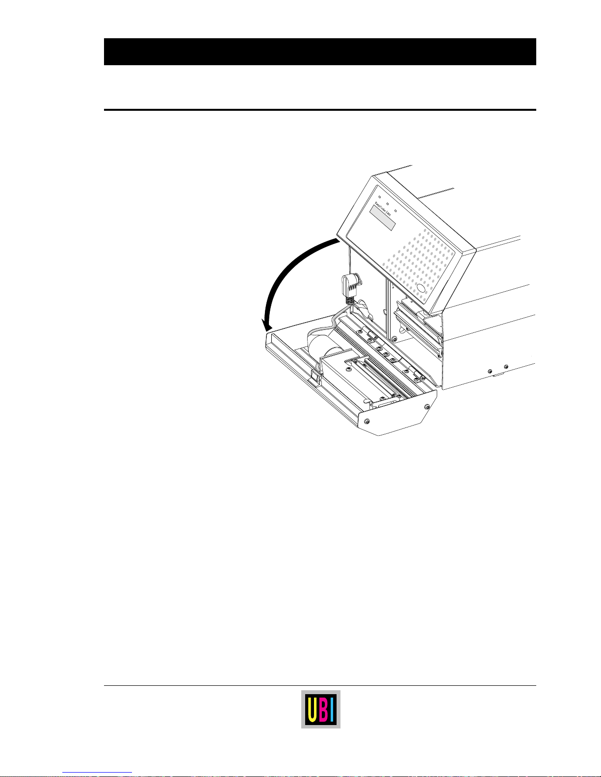
41
UBI EasyCoder 401 Linerless – Technical Manual
LINERLESS PAPER CUTTER, cont'd.
General Information, cont'd. The Linerless Paper Cutter can be tilted forward in order to facilitate
cleaning and paper load.
The cutter is activated by
CUT or CUT ON instructions, see UBI
Fingerprint manuals or UBI Direct Protocol Programmer's Guide.
For more information on how to adapt the paper feed for cut-off
operation, refer to the chapter “Setup Parameters; Detection”
earlier in this manual.
Controlling the Cutter
Print
Power Ready Error
-
Page 42
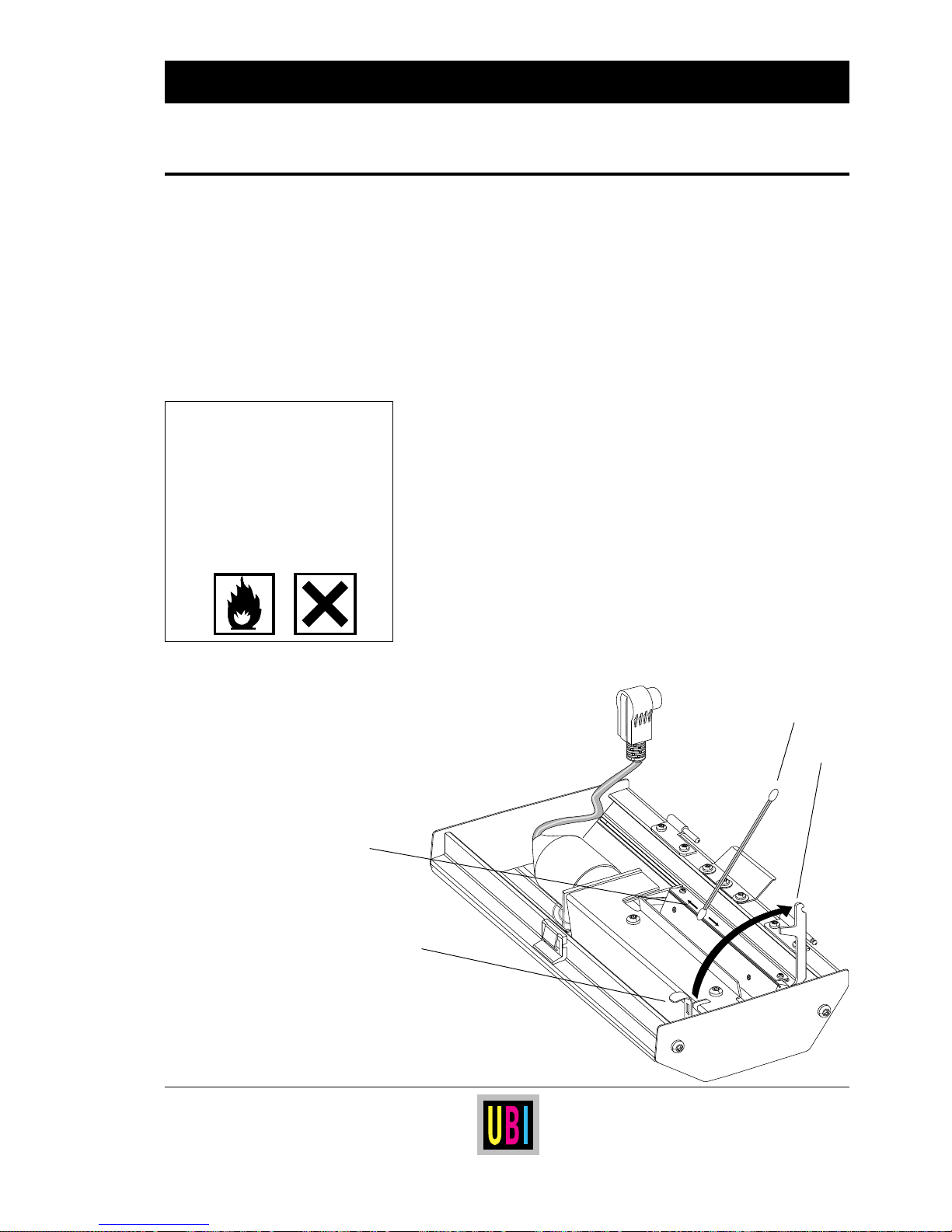
42
UBI EasyCoder 401 Linerless – Technical Manual
The cutter mechanism consists of a rotating shear and a springloaded anvil blade. To prevent the adhesive to stick to the cutting
parts, the rotating shear is lubricated with a thin film of silicon oil
at each cutting cycle, and the anvil blade is provided with a special
“non-stick” coating. Nevertheless, regular cleaning from adhesive
residue at the cutting edge of the anvil blade at an interval of
approximately 50,000 cuts is essential for troublefree operation.
Proceed as follows:
• Fold down the cutter. Be careful not to bend the guide plate, if
fitted.
• Disconnect the spring-loaded brace from the arm at the side
opposite to the motor and fold back the anvil blade. A microswitch
prevents the cutter from being operated while the anvil blade is in
open position.
• Soak a cotton swab with WD-40 multi-spray (or similar)
1
and rub
it against the cutting edge of the anvil blade to dissolve any
adhesive residue.
• Inspect the interior of the cutter for possible shreds of labels,
adhesive residue and similar. If necessary, clean using a cleaning
card or a cotton swab soaked with isopropyl alcohol.
• Close the anvil blade and lock the arm with the brace.
• Fold up the cutter and the printer is ready for operation.
LINERLESS PAPER CUTTER, cont'd.
Cleaning
CAUTION!
WD-40 is an anti-corrosion spray
lubricant manufactured by WD-40
Company Ltd., Milton Keynes, England,
which contains 50% alifatic petroleum
distillate. It is highly flammable and
may be harmful if inhaled or consumed
and at prolonged skin contact. Before
use, carefully read the warning text on
the container.
Arm
Brace
Anvil Blade
Cotton Swab
w. WD-40
1
1
/. In food industry and retail applications
subject to specific regulations, the WD-40
could be replaced with a pure consumable vegetable oil. After dissolving the
residue, carefully wipe clean the anvil
blade.
Page 43
43
UBI EasyCoder 401 Linerless – Technical Manual
General Information
SCALABLE FONTS KIT
All EasyCoder 401 Linerless printers can be fitted with an optional
software package, that allows the printer to use scalable outline
fonts in Speedo and TrueType formats.
The kit consist of two EPROMs and a GAL circuit. The EPROMs
contain a selection of outline fonts and software for scaling them,
whereas the GAL circuit is necessary for the printer to use the
software.
Speedo and TrueType are standard outline font formats for personal
computers developed by Bitstream, Inc. and Apple Computer, Inc.
respectively. There are thousands of different fonts available from
UBI Printer AB at a low cost. The fonts come as files in PC format
and can be downloaded to the printer via the Kermit communication
protocol (see later in this chapter) or be copied to a memory card,
which is inserted in the printer's optional memory card adapter.
The UBI Fingerprint statement
FONT converts the selected outline
font according to the specified characteristics to UBI's bitmap font
format, after which it can be used as any other installed bitmap font
(also see
FONT statement in UBI Fingerprint Reference Manual).
The outline font can by converted in regard of:
• Name
• Size
• Range of characters
• Direction
• Slanting
• Rotation
• Character map table
After the conversion the bitmap font may either be saved in the
battery backed-up part of the RAM memory or in a no-save area (i.e.
the bitmap font will be erased at power-off).
Scaling Fonts in
UBI Fingerprint
This gold label guarantees the quality and
functionality of original Speedo and True-
Type products from UBI.
Products from other suppliers might work,
but the functionality cannot be guaranteed,
nor is any support given by UBI
Page 44

44
UBI EasyCoder 401 Linerless – Technical Manual
SCALABLE FONTS KIT, cont'd.
Downloading Outline Font
Files from a PC
Scalable outline font files come in PC format. Using a personal
computer, such font files can be downloaded to the RAM memory
of the printer. The following description applies to the Terminal
program in Microsoft Windows, but similar methods can be used
with other communication programs that support Kermit.
• Break any program running in the printer, e.g. by pressing the
< C > and < Pause > keys. The printer should be in the Immediate
Mode of UBI Fingerprint.
• Set up the printer and the computer for RS 232C with the same
communication parameters and connect the computer to the
communication port "uart1:" of the printer.
• Check that the communication works both ways by typing e.g.
BEEP on the computer. The printer should respond by emitting
a short beeping sound and return Ok to the computer's screen.
• Set up the printer to receive a file by typing:
TRANSFER K "R" ↵
For more information, refer to the
TRANSFER KERMIT statement
in the UBI Fingerprint Reference Manual.
• In the Terminal program, select:
Settings\Binary Transfer\Kermit.
• Start the transfer of the file by selecting:
Transfers\Send Binary File.
• Select the scalable outline font file you want to transfer, e.g.
BX000003.SPD.
• At the bottom of the window, the progress of the transfer is shown.
Downloading will take a minute or so, depending on the size of
the file.
Page 45
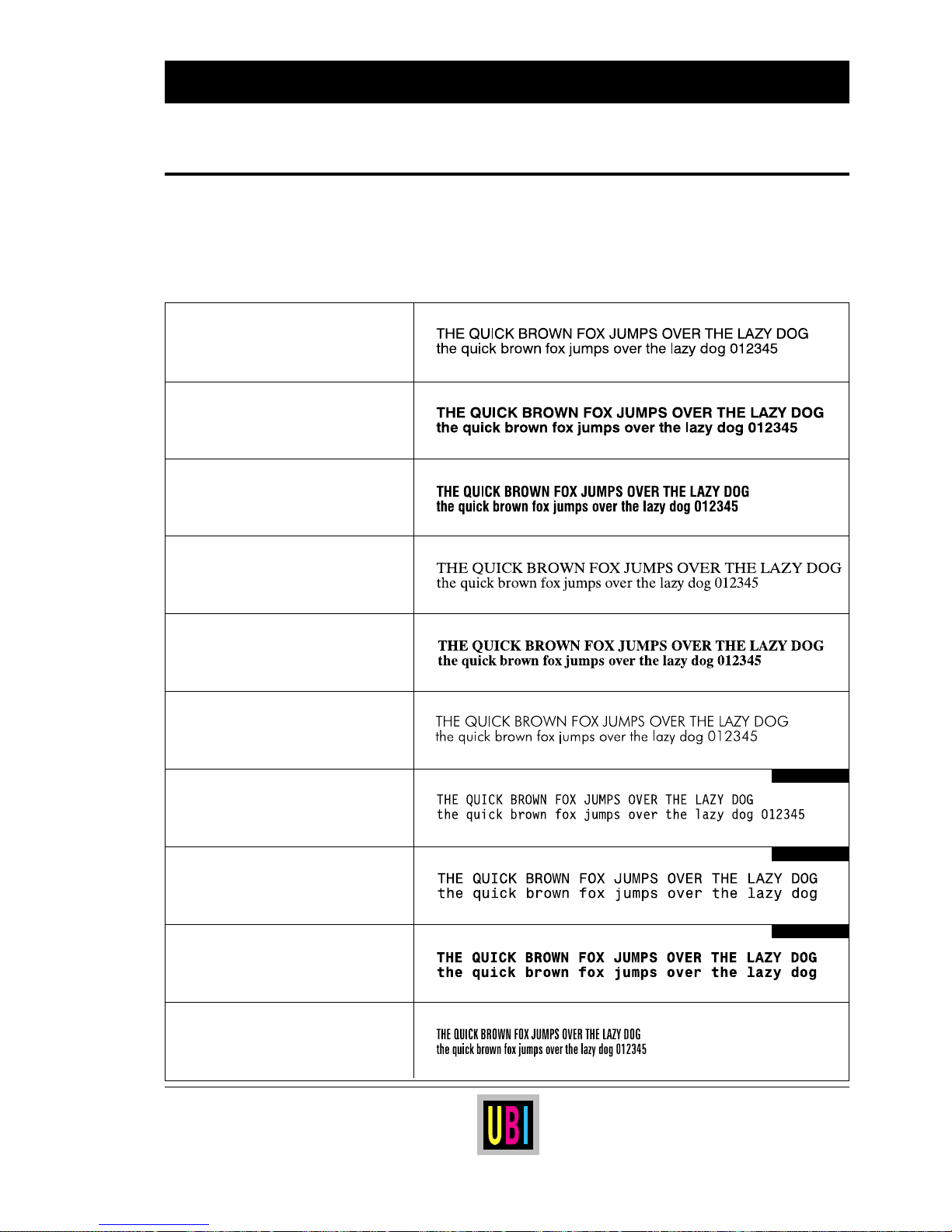
45
UBI EasyCoder 401 Linerless – Technical Manual
SCALABLE FONTS KIT, cont'd.
Printout Samples
The following 10 scalable outline fonts in Speedo format are stored
in the EPROMs of the Scalable Fonts Kit. All characters from
ASCII 32 through 254 decimal according to the Roman 8 character
set are included.
UBI0003.SPD
Bitstream Swiss 721
0003 Roman
UBI0005.SPD
Bitstream Swiss 721
0005 Bold
UBI0010.SPD
Bitstream Swiss 721
0010 Bold Condensed
UBI0011.SPD
Bitstream Dutch 801
0011 Roman
UBI0013.SPD
Bitstream Dutch 801
0013 Bold
UBI0138.SPD
Bitstream Futura
0138 Light
UBI0414.SPD
Bitstream Letter Gothic 12 Pitch
0414 Roman
UBI0596.SPD
Bitstream Monospace 821
0596 Roman
UBI0598.SPD
Bitstream Monospace 821
0598 Bold
UBI0959.SPD
Bitstream Zurich
0959 Extra Condensed
Fixed Spacing
Fixed Spacing
Fixed Spacing
Page 46
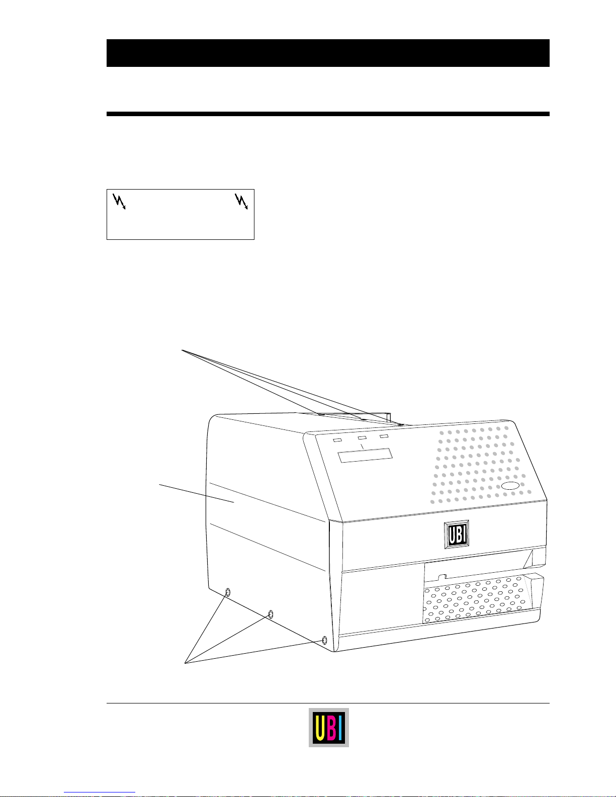
46
UBI EasyCoder 401 Linerless – Technical Manual
EasyCoder 401
Power
Ready
Error
Print
ELECTRONICS
Accessing the CPU Board
WARNING!
Disconnect the power cord
before removing the cover.
Dangerous voltage!
3 Screws
Cover Plate
3 Screws
The CPU board is situated in the electronics compartment on the left
side of the printer's centre-line wall. To gain access to the electronics
compartment, proceed as follows:
❑ Turn off the printer and disconnect the power cord. The CPU
board contains power supply circuits with dangerous voltage.
❑ Remove the three #T10 Torx screws situated along the lower
edge of the cover plate as indicated on the illustration below.
❑ Open the right-hand door and remove the three #T10 Torx
screws at the top of the cover plate.
❑ Remove the cover plate.
❑ Reassemble in reverse order.
Page 47
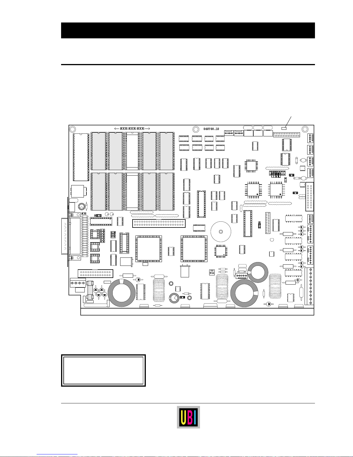
47
UBI EasyCoder 401 Linerless – Technical Manual
POWER ON
040700.10
FLASHEPROM
IC-20
232
CL
422
BW
FW
P-102 P-100 P-101
LTSLSS R-END
DISP
+-
P-208
P-206
P-209
P-207
P-204
P-205
IC-104
IC-105
IC-102
IC-103
IC-100
IC-101
IC-106
IC-107
IC-108
IC-109
FY-300
Power On LED
The CPU board contains a number of jumpers and socket-mounted
circuits, which decide how the printer will work.
The illustration shows the CPU board 1-040700-30.
Before touching the CPU board, carefully read the following
instructions:
• Take precautions to prevent electrostatic discharge.
• Keep in mind that the RAMs and the clock circuit are battery
backed-up. Therefore, there is a risk of short-circuit if any
conductive tools are used on the CPU board.
• When adding or replacing any socket-mounted circuits, make
sure that their “front” markings are pointing in the direction
indicated by the illustration above.
CPU Board
ELECTRONICS, cont'd.
NOTE:
A red lamp (LED) at the upper front
corner of the CPU board is lit
when the power is on.
Page 48
48
UBI EasyCoder 401 Linerless – Technical Manual
ELECTRONICS, cont'd.
The CPU board can be fitted with two, four, or six EPROM
1
packages. Since EPROMs do not require any current to retain their
content and cannot be erased while fitted the printer, they are used
to store programs and files, which are necessary for running the
printer. EPROMs must always be fitted in couples, where both
EPROMs must be CMOS-type of the same size and have a maximum access time of 120 nS. In case of any EPROMs larger than 256
kbyte (2 Mbit), three jumpers must be fitted in the left-hand positions
of P-100, P-101, and P-102.
The CPU board is prepared to have all EPROMs replaced by Flash
Memory packages with an individual size of 512 kbyte (4 Mbit). This
requires special software, and three jumpers must be fitted in the
right-hand positions of P-100, P-101, and P-102.
IC-100 & IC-101
These two EPROMs are alike for all EasyCoder printers with the
same version of the UBI Fingerprint software and always contain:
• The UBI Fingerprint software.
• The default setup (see the chapter “Setup Parameters”).
• Standard bar code generators
1
.
• UPC/EAN bar code interpretation fonts.
• Standard fonts
SW030RSN.1 and SW030RSN.2
2
.
• Setup options for linerless direct thermal paper , see the chapter
“Selecting Paper”.
• Utility programs
MKAUTO.PRG and FILELIST.PRG
2
.
•
UBI.1 image.
IC-102 & IC-103
These two Configuration EPROM's give the printer its special
characteristics and may either contain a standard set of files for the
printer model in question, or a special set of files and application
programs composed according to the customer's requirements.
IC-104 & IC-105
In these two sockets, two additional EPROMs containing e.g.
additional bar codes or software for scaling TrueType and Speedo
fonts can be fitted (see “Scalable Fonts Kit”).
P-100, P-101 & P-102
As standard, these straps are left empty, but three jumpers must be
fitted if any EPROMs larger than 256 kbyte, or Flash Memory
packages, are fitted in sockets IC-100 – IC-105:
Pin 1–2 (r-h pos.) Flash Memory packages
Pin 2–3 (l-h pos.) EPROMs > 256 kbyte
Continued!
UBI Fingerprint
EPROMs
1
/. EPROM is an abbreviation for
Erasable Programmable Read-Only
Memory.
2
/. Please refer to the corresponding
version of the UBI Fingerprint
manuals.
Configuration EPROMs
ROM-expansion EPROMs
Present EPROM Types:
IC-100 & IC-101:
27C010 128 kbyte (1 Mbit)
27C020 256 kbyte (2 Mbit)
IC-102 – IC-105:
27C010 128 kbyte (1 Mbit)
27C020 256 kbyte (2 Mbit)
27C040 512 kbyte (4 Mbit)
Page 49
49
UBI EasyCoder 401 Linerless – Technical Manual
IC-106, IC-107, IC-108 and IC-109
In these sockets either two or four SRAM1 packages, which contain
the printer's working and storage memory, can be fitted. The SRAM
packages must have an access time of max. 120 ns and be fitted in
couples (first couple on IC-106 and IC-107, second on IC-108 and
IC-109).
All SRAM packages must be of the same type and size:
• 2
× 128 kbyte (1 Mbit) = 256 kbyte (2 Mbit)
• 4
× 128 kbyte (1 Mbit) = 512 kbyte (4 Mbit)
• 2
× 512 kbyte (4 Mbit) = 1.024 kbyte (8 Mbit)
• 4
× 512 kbyte (4 Mbit) = 2.048 kbyte (16 Mbit)
The size of the SRAM's is automatically defined by the printer.
The RAM memory is battery backed-up to avoid loss of data when
the printer is turned off or if the power fails. The NiCd-accumulator
is automatically recharged when the power is on. After having
installed the printer, leave the power on overnight to allow the
battery to become fully recharged. If the printer is kept turned on
less than full working hours, it is recommended to leave the power
on overnight at least once a week. Do not leave the printer off for
several weeks (e.g. during holidays) without having made a full
memory backup on a computer disk.
IC-20
The optional real-time clock circuit (RTC) contains a clock/
calendar with battery backup. When an RTC is fitted on IC-20, the
time and date do not have to be set manually each time the printer
is started. (See
TIME$ and DATE$ in the UBI Fingerprint manuals
or in the UBI Direct Protocol Programmer's Guide).
When installing an RTC, be careful to fit it with the semi-circular
marking pointing upward, as seen when the CPU board is fitted in
the printer. Because of the risk of short-circuits, do not use any
conductive tools when fitting or removing the RTC.
FY-300
The CPU board contains components for transforming the mains
current into the various voltages required by the logics and the
printhead. The CPU board is protected by a fuse situated at the lower
left corner of the board.
Never replace a blown fuse without having found and remedied the
fault, that caused it to blow. That usually requires the assistance of
a skilled service technician.
ELECTRONICS, cont'd.
RAM Memory
Real-time Clock Circuit
Fuse
WARNING!
The semicircular “front” marking of
each package should face upward as
seen when the CPU board is fitted
in the printer.
If a RAM package is fitted upside
down, the recharging of the CPU
board's battery backup could be
damaged. This will eventually cause
memory loss.
1
/. SRAM is an abbreviation for Static
Random Access Memory.
Page 50
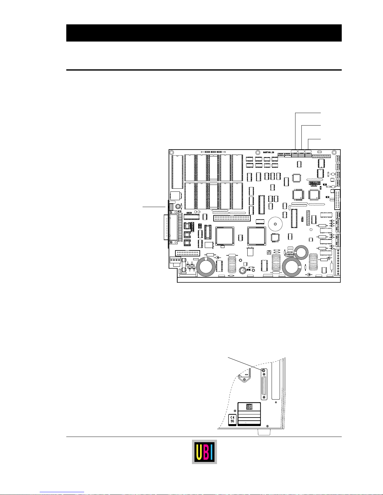
50
UBI EasyCoder 401 Linerless – Technical Manual
POWER ON
040700.10
FLASHEPROM
232
CL
422
BW
FW
P-102 P-100 P-101
LTSLSS
P-604
P-607
R-END
DISP
+-
P-208
P-206
P-209
P-207
P-204
P-205
MADE IN SWEDEN
Type
Art. No.
Ser. No.
115/230 V 2.6/1.3 A 50–60 Hz
TA
The CPU board is fitted with four potentiometers with the following
functions:
• Display contrast adjustment
• Label stop sensor (LSS) adjustment
• Label-taken sensor (LTS) adjustment
• Ribbon end sensor (R-End) adjustment
(not used)
❑ Display Contrast Adjustment:
This potentiometer is situated close to the connector of "uart1:"
and can be accessed through a small hole in the rear plate. Using
a narrow-tipped screwdriver, turn the screw in either direction
until the text in the LCD display on the printer's front becomes
clearly visible in the prevailing light conditions when viewed
from a normal working position.
ELECTRONICS, cont'd.
Potentiometers
Continued!
Display Adjustment
LSS
LTS
(R-End)
Display
Page 51

51
UBI EasyCoder 401 Linerless – Technical Manual
The remaining three potentiometers are situated along the top edge
of the CPU board and can only be accessed after the left-hand cover
plate has been removed. Normally, they do not require any adjustment.
❑ Label Stop Sensor Adjustment:
This potentiometer is used in connection with the printer's Setup
Mode for adjusting the sensitivity of the label stop sensor. In
most cases, it will be sufficient to use the adjustment method
offered in the Setup Mode and the Testfeed facility.
❑ Label-Taken Sensor Adjustment
The label-taken sensor is either fitted inside the paper cutter
(standard in EasyCoder 401 LLC) or above the paper outfeed
slot (option in EasyCoder 401 LLT) and detects if a label has not
been removed from the outfeed area. Thereby, the printer can be
programmed not to print any more copies before the last copy
has been removed. The operation of this sensor depends to a
large extent on the reflectivity of the labels (e.g. glossiness,
colour etc.). Thus, it may sometimes require adjustment when
switching between different types of labels.
In case of an LTS optionally fitted to the front of an EasyCoder
401 LLT, the light intensity of the emitter can be changed
between two values by means of fitting or removing a strap on
P-607 (strap fitted = increased intensity). No such strap must be
fitted on an EasyCoder 401 LLC.
❑ Ribbon End Sensor Adjustment:
Obviously, this sensor is omitted since the printer is not fitted
with any transfer ribbon mechanism.
Before changing the setting of a potentiometer, always make
sure that the corresponding sensor is clean, free from obstructions (e.g. pieces of labels or adhesive residue), and properly
aligned.
ELECTRONICS, cont'd.
Potentiometers, cont'd.
Caution!
If some adjustment nevertheless
must be performed, it has to be
done with utmost care. Since the
power must be on during the adjustment procedure, precautions
must be taken to avoid any risk of
electrical shock or short-circuits!
Use non-conductive tools and keep
fingers away from the CPU board,
especially the area behind it, where
the mains inlet and mains switch
are situated.
Page 52
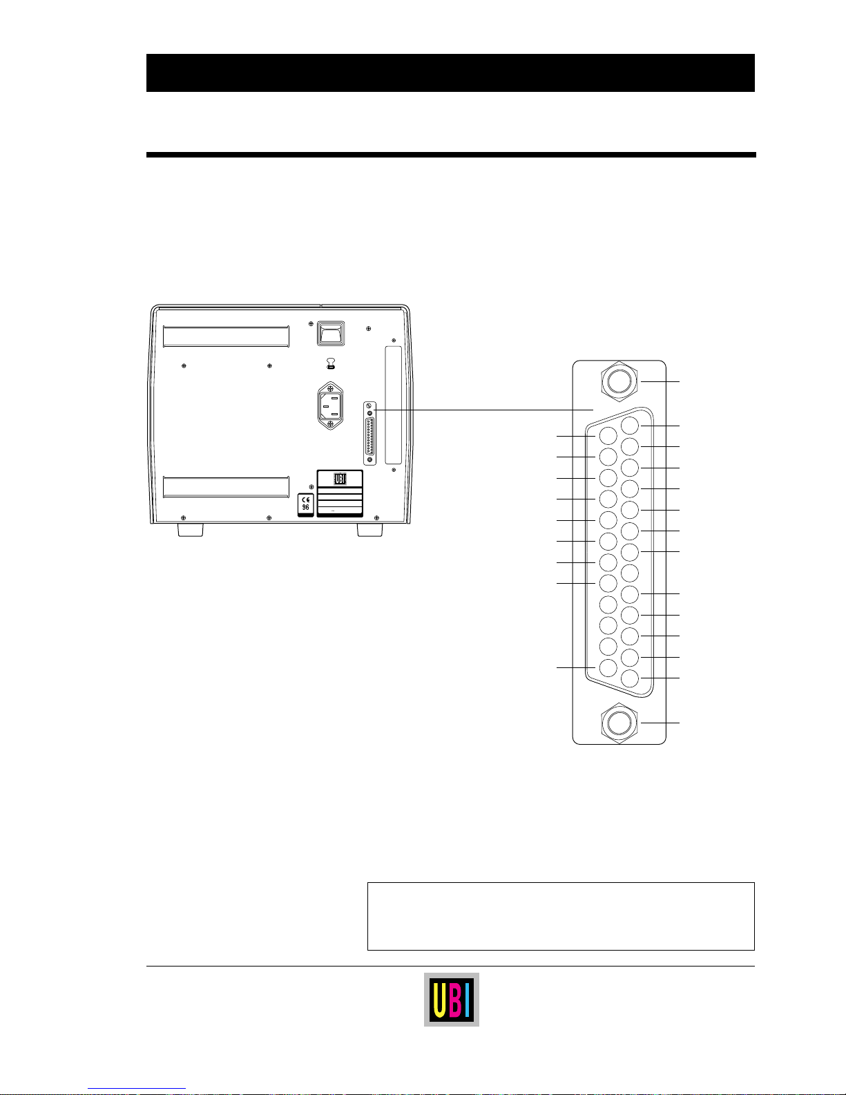
52
UBI EasyCoder 401 Linerless – Technical Manual
INTERFACES
Communication Port
"uart1:"
All EasyCoder 401 printers are fitted with a DB25 male interface
connector on their rear plates (comm. port "uart1:"). This connector
can be used for an RS 232C, an RS 422, or a 20 mA current loop
interface depending on how the CPU board is strapped. In the latter
two cases, additional circuits must be fitted. The configuration of
the connection cable is also important.
If the printer is ordered without any connection cable, a suitable
cable can be procured locally and, if necessary, be modified
according to the pinout descriptions in this chapter.
NOTE!
A shielded communication cable is required in order to comply
with the FCC/DOC approval and to avoid
the risk of interference to radio communications.
GNDC
2
1
3
4
5
6
7
8
9
10
11
12
13
15
14
16
17
18
19
20
21
22
23
24
25
GNDC
TXD out
RXD in
RTS out
CTS in
DSR in
GNDI
+20 mA 1
-20 mA 1
+TXD
-TXD
+20 mA 2
GNDC
-20 mA 2
+RS 422 In
+5V Ext.
-RS 422 In
+RXD
+RS 422 Out
DTR out
-RS 422 Out
-RXD
Signals on the printer's
communication port "uart1:"
0
230V
MADE IN SWEDEN
Type
Art. No.
Ser. No.
115/230 V 2.6/1.3 A 50–60 Hz
TA
UART = Universal Asynchronous
Receiver and Transmitter
Page 53
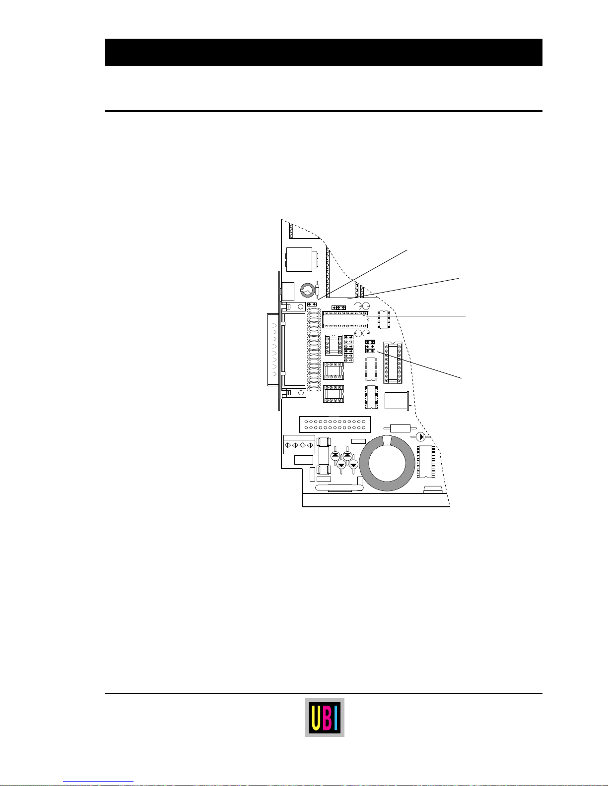
53
UBI EasyCoder 401 Linerless – Technical Manual
232
CL
422
"UART1:"
P202
IC-200
P203
3 2 1
P200
+-
RS 232C (V24) is the most common interface for serial communication with computers over short distances. The transmission can
only take place between one transmitter and one receiver. The most
simple form of two-way communication only requires a 3-wire
cable. The maximum transmission distance is about 10–15 metres
(33–49 ft.) and the maximum transmission speed is 19,200 baud.
■ RS 232C circuit must be fitted on IC-200 (fitted as standard).
■ Jumper must be fitted on uppermost position of P-202.
❑ RS 422 circuit on IC-207, opto-couplers on IC-205 and IC-206
(optional) and straps on P-204 – P-209 are of no consequence.
The following hardware straps can be fitted:
P-200 DTR-signal:
Pin 1–2 DTR indicates printer turned on.
Pin 2–3 A copy of the flow signal RTS is produced.
P-203 External 5 Volt
1
:
Jumper fitted connects +5V to pin 16. Warning! Max 200 mA.
INTERFACES, cont'd.
RS 232C (V24) on "uart1:"
Continued!
IC-200
(RS 232C circuit)
P-203
(external +5V)
P-202
(Interface select)
P-200
(DTR/RTS select)
1
/. Warning! Be careful not to enable the
external 5V unintentionally, which may
cause harm to the terminal, PC or other
device connected to this port!
Page 54
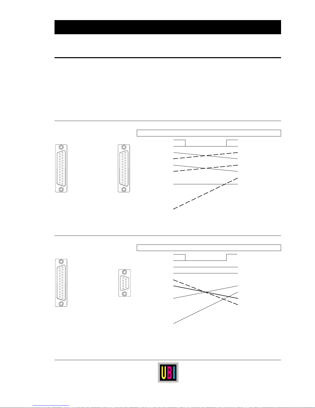
54
UBI EasyCoder 401 Linerless – Technical Manual
12345678910111213
141516171819202122232425
12345678910111213
141516171819202122232425
12345678910111213
141516171819202122232425
12345
6789
Cable configuration:
The following ready-made RS 232C connection cables can be
ordered from UBI. Cables procured from other sources should
follow the same wiring principles.
Note:
Be careful not to connect the external +5V unintentionally, which
may harm your computer or terminal.
To Printer ("uart1:") To IBM-XT & PS/2
DB25 female connector ⇐ cable ⇒ DB25 female connector
Housing • • Housing
Cable shield 1 • • 1 Cable shield
TXD out 2 • • 2 TXD out
RXD in 3 • • 3 RXD in
RTS out 4 • • 4 RTS out
CTS
1
in 5 • • 5 CTS in
DSR in 6 • • 6 DSR in
Signal GND 7 • • 7 Signal GND
not used 8-15 • • 8-25 not used
(+5V) 16 •
not used 17-19 •
DTR out 20 •
not used 21-25 •
To Printer ("uart1:") To IBM-AT
DB25 female connector ⇐ cable ⇒ DB9 female connector
Housing • • Housing
Cable shield 1 • • 1 not used
TXD out 2 • • 2 RXD in
RXD in 3 • • 3 TXD out
RTS out 4 • • 4 not used
CTS
1
in 5 • • 5 Signal GND
DSR in 6 • • 6 DSR in
Signal GND 7 • • 7 RTS out
not used 8-15 • • 8 CTS in
(+5V) 16 • • 9 not used
not used 17-19 •
DTR out 20 •
not used 21-25 •
INTERFACES, cont'd.
1
/. If the communication cable is not
configured to transmit any CTS signal to
the printer, a permanent CTS signal will
automatically be produced.
Printer ⇒ IBM-XT/IBM-PS2
Art.No. 1-975580-05
Length: 3 metres (9.8 ft.)
Printer ⇒ IBM-AT
Art.No. 1-975581-05
Length: 3 metres (9.8 ft.)
➠
➠
1
/. If the communication cable is not
configured to transmit any CTS signal to
the printer, a permanent CTS signal will
automatically be produced.
RS 232C (V24) on "uart1:",
cont'd.
Page 55
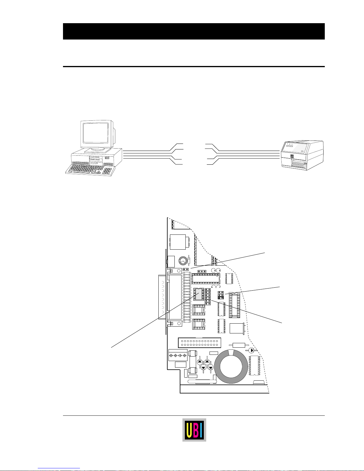
55
UBI EasyCoder 401 Linerless – Technical Manual
232
CL
422
"UART1:"
P202
IC-207
P203
P208
P206
P209
P207
P204
P205
+-
INTERFACES, cont'd.
RS 422 is a point-to-point interface for connection between one
printer and one host computer over a distance of up to 1,200 metres
(4,000 ft.) by use of a four-wire cable. The transmission is full
duplex, i.e. reception and transmission can take place simultaneously.
RS 422 requires an additional circuit and a number of straps to be
fitted on the CPU board:
RS 422 on "uart1:"
Continued!
RS 422 connection between host computer and printer
+ RS422 IN
- RS422 IN
+ RS422 OUT
- RS422 OUT
Power
Ready
Error
EasyCoder 401
Print
P-204 – P-209
(comm. straps)
P-202
(interface select)
P-203
(external +5V)
IC-207
(RS 422 circuit)
Page 56
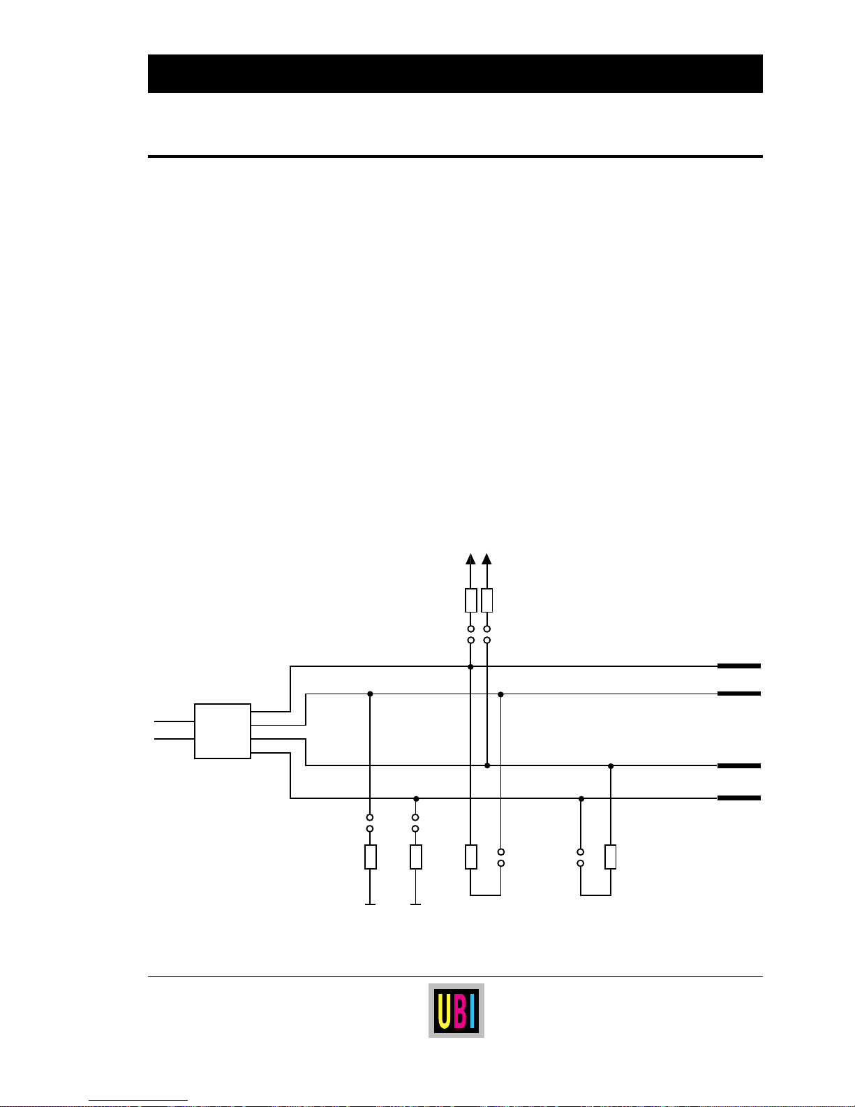
56
UBI EasyCoder 401 Linerless – Technical Manual
INTERFACES, cont'd.
RS 422 on "uart1:", cont'd.
On the CPU board, check:
■ An optional RS 422 circuit must be fitted on IC-207.
■ Jumper must be fitted on the lowest position of P-202 to select
RS 422.
■ Jumper must be fitted on some of P-204 – P-209 according to
diagram below.
❑ RS 232C circuit on IC-200 (standard), jumper on P-200, and
opto-couplers on IC-205 and IC-206 (optional) are of no consequence.
P-203 External 5 Volt
1
:
Jumper fitted connects +5V to pin 16. Warning! Max. 200 mA.
(Note that +5V requires an additional wire in the cable).
P-204 – P-209 Communication straps:
Jumpers can be fitted on P-204, P-205, P-206, P-207, P-208 and/or
P-209 in order to adapt the RS 422 communication to the host, as
shown in the diagram below. Normally, jumpers should be fitted on
P-205, P-207 and P-209.
1
/. Warning! Be careful not to enable the
external 5V unintentionally, which may
cause harm to the terminal, PC or other
device connected to this port!
IC-207
DI
RO
RI+
RI-
DO+
DO-
+ RS422 IN
- RS422 IN
+ RS422 OUT
- RS422 OUT
15
17
19
21
P-201
("uart1:")
+5V +5V
P-208 P-209
P-206 P-207
P-204 P-205
/TXD
/RXD
4.7k
4.7k
100
100
4.7k
4.7k
Page 57
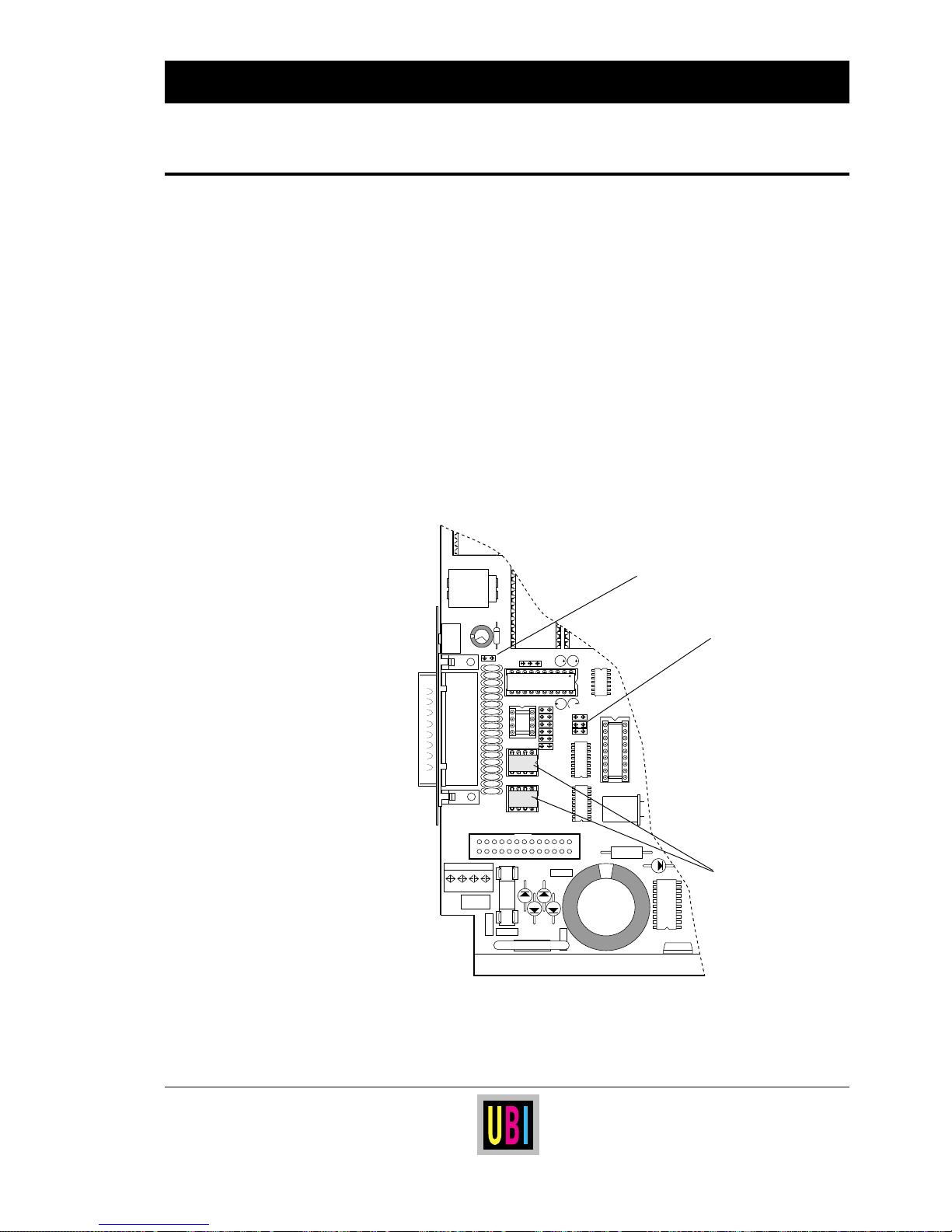
57
UBI EasyCoder 401 Linerless – Technical Manual
The 20 mA current loop interface is a single-ended, full duplex
serial interface which uses current instead of voltage to transmit
signals on a four-wire line. 20 mA current corresponds to a logical
“0” and 0 mA corresponds to a logical “1”.
Opto-couplers are used to separate the transmission line from the
internal logics of the printer and the host computer. Therefore this
interface is suitable where electrical interference may occur, and for
transmission over longer distances (up to 500 metres or 1,500 ft.).
Depending on the configuration of the connection cable between
printer and host computer, the printer can work either active (i.e.
supplying the current) or passive. A transmission speed between
300 and 9,600 baud is recommended.
232
CL
422
"UART1:"
P202
IC-205
IC-206
P203
+-
20 mA Current Loop
on "uart1:"
INTERFACES, cont'd.
Continued!
P-203
(external +5V)
IC-205 & IC-206
(opto-couplers)
P-202
(interface select)
Page 58

58
UBI EasyCoder 401 Linerless – Technical Manual
20 mA Current Loop
on "uart1:", cont'd.
INTERFACES, cont'd.
On the CPU board, check:
■ Opto-couplers must be fitted on IC-205 and IC-206. These are
not included as standard and must be ordered separately.
■ Jumper must be fitted on middle position of P-202 to select 20
mA current loop.
❑ RS 422 circuit fitted on IC-207 (optional), RS 232C circuit fitted
on IC-200 (standard) and jumpers fitted on P-204 – P-209 or on
P-200 are of no consequence.
P-203 External 5 Volt:
Jumper fitted connects +5V to pin 16. Warning! Max. 200 mA.
Be careful not to enable the external 5V unintentionally, which may
cause harm to the terminal, PC or other device connected to this
port!
Cable configuration:
The printer end of the connection cable should have a DB25 female
connector. The computer end of the cable depends on your type of
computer.
The printer's connector contains the following signals:
Pin 9 + 20 mA
Pin 10 – 20 mA
Pin 11 TXD +
Pin 12 TXD –
Pin 13 + 20 mA*
Pin 14 – 20 mA*
Pin 16 + 5V, 200 mA (if jumper fitted on P-203)
Pin 18 RXD +
Pin 25 RXD –
*. In case of printer being active receiver.
Continued!
Page 59
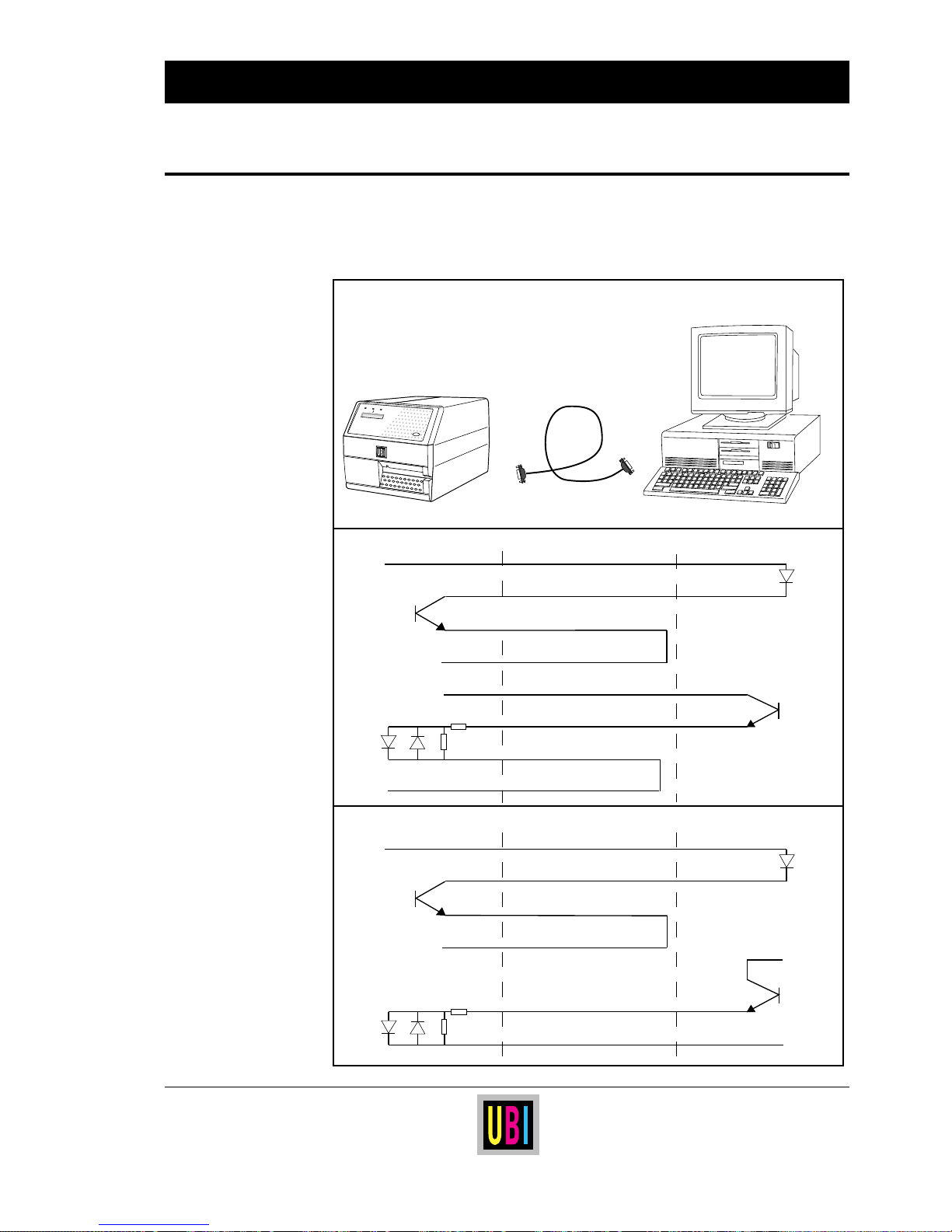
59
UBI EasyCoder 401 Linerless – Technical Manual
INTERFACES, cont'd.
PRINTER
CABLE
COMPUTER
+
-
+
-
Transmitter
Receiver
47 ohm
270
ohm
Pin 9
Pin 11
Pin 12
Pin 10
Pin 13
Pin 18
Pin 25
Pin 14
TXD+
TXD-
RXD+
RXD-
+
+
-
Transmitter
Receiver
47 ohm
270
ohm
Pin 9
Pin 11
Pin 12
Pin 10
Pin 18
Pin 25
TXD+
TXD-
RXD+
RXD-
Printer active transmitter/active receiver
Printer active transmitter/passive receiver
Power
Ready
Error
EasyCoder 401
Print
The examples below illustrate two of four possible cases of the
printer or host computer being active transmitter or receiver, i.e.
being the supplier of the current to the loop.
20 mA Current Loop
on "uart1:", cont'd.
Page 60
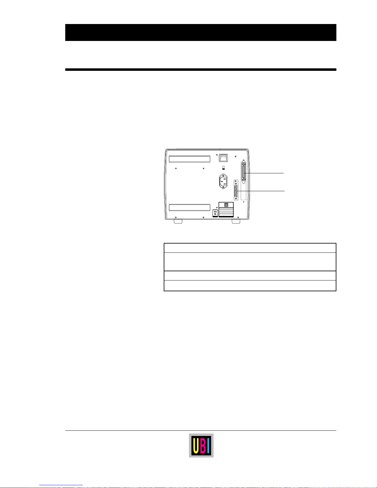
60
UBI EasyCoder 401 Linerless – Technical Manual
The Parallel Interface Board adds one extra parallel communication
port ("centronics:") to the standard serial communication port
("uart1:").
The Parallel Interface Board may either be bought separately as a
kit complete with installation instructions, or be factory installed.
The following types of interfaces can be selected:
"uart1:"
Fitted on printer's CPU pcb.
RS 232C Standard.
RS 422 or 20 mA CL Option. Additional circuits required.
"centronics:"
Fitted on Parallel interface pcb.
Centronics parallel interface
The setup is in no way affected by the Parallel Interface Board, since
the Centronics interface does neither require any communication
setup nor uses any buffers.
INTERFACES, cont'd.
Parallel Interface Board
230V
0
MADE IN SWEDEN
Type
Art. No.
Ser. No.
115/230 V 2.6/1.3 A 50–60 Hz
TA
"centronics:"
"uart 1:"
Page 61
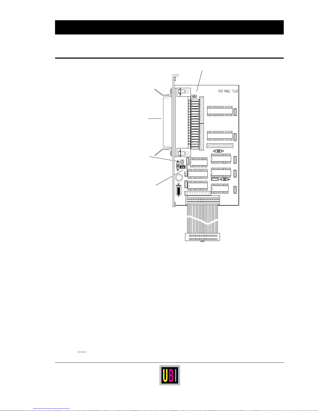
61
UBI EasyCoder 401 Linerless – Technical Manual
INTERFACES, cont'd.
Three different straps can be fitted on the Parallel Interface Board:
External +5V
Jumper fitted on connector P-2 enables external +5V (max. 200
mA) on pin 18.
Warning! Be careful not to enable the external +5V unintentionally, which may cause harm to the terminal, computer or other
device connected to this port!
Busy Signal:
S1: Jumper fitted = BUSY signal on until end of ACK signal.
No jumper fitted =
ACK after BUSY signal (as on previous
versions of this board).
S2/S3
1
: Jumper fitted on S-2 = BUSY signal on falling edge of
/STROBE signal (i.e. according to specifications)
Jumper fitted on S-3 =
BUSY signal on rising edge
of
/STROBE signal (i.e. as on previous versions of this
board).
1
/. A jumper must be fitted on either S-2 or
S-3.
P-2
Female
Centronics
connector
S-2/S-3
S-1
P2
S1
S3
S2
Parallel Interface Board,
cont'd.
Page 62
62
UBI EasyCoder 401 Linerless – Technical Manual
Connector configuration
The connector is the standard female 36-pole Centronics type. The
mounting holes are connected to chassis ground.
Note:
The PE signal (Paper End) on pin 12 requires an error-trapping
routine to be included in the UBI Fingerprint software, activating
the
BUSY and READY statements. Here is an example on how such
a routine may be written:
10 IF (PRSTAT AND 4) THEN GOSUB 1000
20 IF (PRSTAT AND 4) = 0 THEN GOSUB 2000
. . . .
. . . .
. . . .
1000 BUSY4
1010 RETURN
2000 READY4
2010 RETURN
Also see BUSY and READY statements and PRSTAT function in the
UBI Fingerprint manuals.
INTERFACES, cont'd.
Parallel Interface Board,
cont'd.
Pin Signal Dir. Remarks
1 /STROBE In
2 DATA 0 In
3 DATA 1 In
4 DATA 2 In
5 DATA 3 In
6 DATA 4 In
7 DATA 5 In
8 DATA 6 In
9 DATA 7 In
10 ACK Out
11 BUSY Out
12 PE Out See note!
13 SELECT Out
14–15 – – not used
16–17 GND
18 + 5V Out If strap fitted on P-2. Max. 200 mA.
19–30 GND
31 /INPRM In
32 /ERROR Out
33–35 – – not used
36 /SLCTIN In
37–38 GND Housing
UBI offers a 3 metres (9.8 ft.) long
ready-made parallel communication
cable (36-p male Centronics – DB25
male).
Article No. 1-010001-00
 Loading...