

Page 1
!
UBC1319AA00
DOCSIS 3.0
Wireless eMTA
Quick
Installation
Guide
Page 2
!
UBC1319AA00
D3.0 Wireless eMTA
Quick Installation Guide
Subscriber
Grounding the Device: Install the cable modem to include
grounding the coaxial cable to the earth as close as practical to
the building entrance per ANSI/NFPA 70 and the National
Electrical Code (NEC, in particular, Section 820.93, Grounding of
the Outer Conductive Shield of a Coaxial Cable). The device is
designed for IT power systems with phase-to-phase voltage at
120V.
This unit requires a 100-240V, 50/60Hz power adapter. The
power adapter must be keyed for proper polarization, and must
be fully inserted to contact the back of the power connector
port to ensure snug connection. Do NOT use any other power
adapter.
Disconnecting the Device: If the cable modem becomes
damaged or encounters some other abnormality, disconnect the
power plug from the AC wall outlet immediately.
Temperature and Altitude: Install the device in a location not to
exceed the maximum temperature of 104°F (40°C). Regular
operating altitude is 2000 m, and maximum operating altitude
is 4500 m.
•
SAFETY NOTICES
•
PREPARING FOR INSTALLATION
✓
Locate the RF (coaxial) cable connector on the wall.
✓
Verify the power outlet is working and is wired correctly.
✓
Place your cable modem within a proper distance from the
outlet.
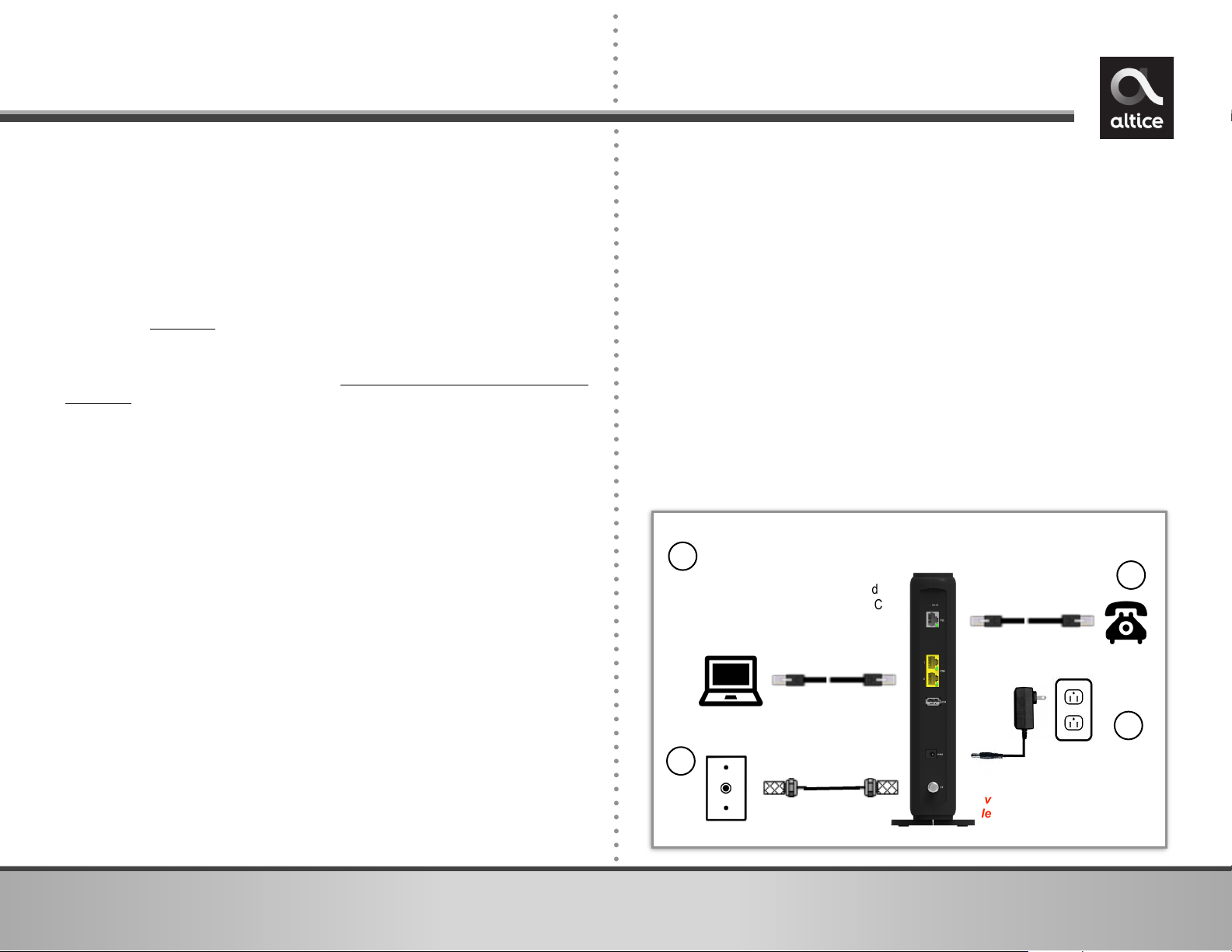
To connect a modem and a television to the same wall outlet,
you must use a cable line splitter (not included).
2. Connect an Ethernet cable (supplied) to one of the ETH
(Ethernet) port on the back panel of the modem and connect
the other end to the Ethernet port of a computer. Use a
Category 5e or Category 6 Ethernet cable with RJ-45
connectors to ensure Gigabit Ethernet speeds (when the
computer supports it).
3. Connect an RJ-11 phone cable (not supplied) to the TEL
(telephone) port on the modem (when provisioned for voice
service as specified by the service provider), and connect the
other end to the phone port of the telephone. If voice service
is not provisioned through the service provider, telephone
service is not available.
4. Connect the power adapter (supplied) to the PWR (power)
port. Connect the other end to a power outlet.
1
UBC1319AA00
Wireless Voice Gateway
RJ-45
Analog Phone
RJ-11
Cable/RF
Device must be installed
vertically using the included
leg stands to obtain optimum
wireless performance.
Connect computers or Ethernet enabled
devices (wireless switch or router). A PC
should be connected for initial device
installation and configuration.
2
1
3
4
1. Connect the included leg stands to the bottom of the device
to enable the modem to be installed vertically. Connect the
coaxial cable (not supplied) to the RF (cable) connector on
the rear panel of the modem and connect the other end to
the cable wall outlet. Do not bend or over tighten the cable,
as this may strain the connector and cause damage.
•
INSTALLING THE UBC1319AA00
Page 3

!
•
DEVICE WALL MOUNT INSTRUCTIONS
2
Label
Millimeters
(mm)
A
7.2 +/- 0.5
B
2.6 +/- 0.15
C
19.0 +/- 1.2
D
3~4
UBC1319AA00 Quick Installation Guide
5. Separate the wall mounting pieces. Mount the top and
bottom leg stand pieces (Figure 1) onto the UBC1319AA00
as shown in Figure 2.
6. You can now mount the UBC1319AA00 onto the wall using
the screws installed in Step 4.
2. Fit the 2 leg stand pieces
together with the wall mount
template as represented in the
graphic to the right.
3. Place this on the wall and use it
as a template to mark the wall
for the appropriate placement
of the screws.
4. Install the 2 sets of screws on
the wall (158 mm or 6.2 inches
apart).
NOTE: The screws should protrude
from the wall so you can fit the
device between the head of the
screws and the wall. If you install
the screws in drywall, use hollow
wall anchors to ensure the unit
does not pull away from the wall
due to prolonged strain from the
cable and power connectors.
You can mount the UBC1319AA00 on a wall by following the
steps below:
1. You will need 4 round or pan head screws with the following
measurements:
Figure 1
Figure 2
Page 4

!
•
DEVICE CONNECTIONS AND BUTTONS
RESET: To reset the device, take a small object like the end of a
paper clip and insert it into the RESET opening. To power cycle
the device, hold for less than 5 seconds. To reset to factory
default settings, hold for more than 5 seconds. WARNING:
Resetting factory defaults will erase ALL settings that you have
made and will restore the device to factory default settings.
TEL: Connects an analog telephone using an RJ11 cable.
ETHERNET 1-2: Connects Ethernet-enabled devices such as
computers, gaming consoles or a wireless access point (router)
using RJ45 Ethernet cables.
USB: Connects to USB devices.
PWR: Connects to the supplied power adapter. Plug the other
end into the wall power outlet.
CABLE: Connects to the cable wall outlet using a coaxial cable.
WPS: On the front panel, the WPS button is used for the Wi-Fi
Protected Setup (WPS) push button method to connect a client
Wi-Fi device to the UBC1319AA00. When a user pushes the WPS
button or triggers WPS via the Web UI, it flashes for 4 minutes
until the WPS button is pushed on the wireless client device.
After a WiFi client attaches successfully, the LED remains on for
5 minutes, then turns off.
INFO: On the front panel, the INFO button controls the LED ECO
Mode.
•
When enabled, LED ECO Mod e allows the modem to
automatically turn off the LEDs in order to conserve energy.
Note that the POWER LED will remain lit in ECO Mode.
•
When pushed, the INFO button will disable the LED ECO Mode
for 30 seconds, and the LEDs will operate in the Normal State as
seen in the LED table on page 4.
•
When the modem is in a faulty or alarm condition, LED ECO
Mode is automatically disabled. When the condition is resolved,
the device will again enable LED ECO Mode.
•
By default, LED ECO Mode is automatically enabled 3 minutes
after powering up the modem.
•
BASIC MODEM INFORMATION
3
UBC1319AA00 Quick Installation Guide
Example of Cable
RF MAC Address
00:71:CC:8E:54:C7
Firmware Version
UBC1319AA00-1xxx-v1.0.0rx
Compatibility
DOCSIS 3.0/2.0/1.0 certified
Ethernet 10/100/1000 Mbps
Wireless 802.11a/b/g/n/ac
Local Web Page
User Access
http://192.168.100.1 or http://192.168.0.1
Local Web Page
Login (web UI)
Login: MSO
Password: changeme
Encryption
WPA2-PSK with AES encryption
Wireless Default
SSID (wireless
network name)
“MyAltice” then a space, and the last 6
characters of the WAN MAC address (in
lower case). The SSID is the same for both
the 2.4 and 5GHz radio bands.
SSID Examples
2.4GHz radio with above MAC address:
SSID = MyAltice 8e54c7
5GHz radio with above MAC address:
SSID = MyAltice 8e54c7
WPA2-PSK
Wireless Key
Six digits (0-9) – in groupings of 2, 3 or 4
digits, two hyphens, and one name of a
color. It can be found on the device label.
This is your wireless password.
WPA2-PSK
Wireless Key
Example
5112-orange-91
Page 5

!
4
•
LED BEHAVIOR
UBC1319AA00 Quick Installation Guide
LED
Normal State
Normal State
(LED ECO Mode Enabled)
Faulty/Alarm State
(LED ECO Mode is Automatically Disabled)
FRONT PANEL
DS/US
(downstream/
upstream)
ON Solid White
OFF
Blinks White = Problem on the network and
device cannot link properly
INTERNET
ON Solid White
OFF
Blinks White = CPE fails to obtain IP address
WPS
Blinks White = WPS button is
pushed
(otherwise will be OFF)
OFF
N/A
WIFI
On Solid White = WiFi Enabled
OFF = WiFi Disabled
OFF
Blinks White = WiFi initialization issue
PHONE
On Solid White = eMTA
Registered Successfully
OFF = eMTA Disabled
OFF
Blinks White = eMTA registration failed
POWER
ON Solid White
ON Solid White
N/A (but will remain ON if power connected)
REAR PANEL
TEL
ON Solid Green = Telephone is connected
Blinks Green = Telephone call in progress
OFF = Telephone is NOT connected
ETH 1-2
ON Solid Green = Ethernet device is connected
Blinks Green = Data being transmitted
OFF = Ethernet device is NOT connected
Page 6

•
FEDERAL COMMUNICATION COMMISSION
(FCC) INTERFERENCE STATEMENT
This device complies with Part 15 of the FCC Rules. Operation is
subject to the following two conditions: (1) This device may not
cause harmful interference, and (2) this device must accept any
interference received, including interference that may cause
undesired operation.
This equipment has been tested and found to comply with the
limits for a Class B digital device, pursuant to Part 15 of the FCC
Rules. These limits are designed to provide reasonable
protection against harmful interference in a residential
installation. This equipment generates, uses and can radiate
radio frequency energy and, if not installed and used in
accorda n ce wit h the in structi o ns, may cause h armful
interference to radio communications. However, there is no
guarantee that interference will not occur in a particular
installation. If this equipment does cause harmful interference to
radio or television reception, which can be determined by
turning the equipment off and on, the user is encouraged to try
to correct the interference by one of the following measures:
• Reorient or relocate the receiving antenna.
• Increase the separation between the equipment and
receiver.
• Connect the equipment into an outlet on a circuit different
from that to which the receiver is connected.
• Consult the dealer or an experienced radio/TV technician
for help.
5
UBC1319AA00 Quick Installation Guide
5GHz Wireless Statement:
For operation within the 5.15~5.25GHz and 5.47~5.725GHz
fre q uency ra n ges, this d evice is restric ted to in d o or
environments.
This device meets all the other requirements specified in Part
15E, Section 15.407 of the FCC Rules.
FCC Caution:
Any changes or modifications not expressly approved by the
party responsible for compliance could void the user's authority
to operate this equipment.
This transmitter must not be co-located or operating in
conjunction with any other antenna or transmitter.
Radiation Exposure Statement:
This equipment complies with FCC radiation exposure limits set
forth for an uncontrolled environment. This equipment should be
installed and operated with minimum distance 30 cm between
the radiator & your body.
This reminder is provided to call the CATV systems installer's
attention to section 820-93 of the National Electric Code, which
provides guidelines for proper grounding and in particular,
specify that the Coaxial cable shield shall be connected to
grounding system of the building, as close to the point of cable
entry as practical.
•
NOTE TO CATV INSTALLER
 Loading...