

Page 1
!
UBC1310BA10
DOCSIS 3.0
Advanced Wireless Voice Gateway
Quick Installation Guide - Subscriber
Page 2
!
www.ubeeinteractive.com
UBC1310BA10
Advanced Wireless Voice Gateway
Quick Installation Guide
Subscriber User
Grounding the Device: Install the cable modem to include
grounding the coaxial cable to the earth as close as practical to
the building entrance per ANSI/NFPA 70 and the National
Electrical Code (NEC, in particular, Section 820.93, Grounding of
the Outer Conductive Shield of a Coaxial Cable).
This unit requires a 100-240V, 50/60Hz power adapter. Power
cable must be keyed for proper polarization, and must be fully
inserted to contact the back of the power connector port to
ensure snug connection. Do NOT use any other power adapter.
Disconnecting the Device: If the cable modem becomes
damaged or encounters some other abnormality, disconnect the
power plug from the AC wall outlet immediately.
Temperature and Altitude: Install the device in a location not to
exceed the maximum temperature of 40˚ Celsius). Regular
operating altitude is 2000 m, and maximum operating altitude is
5000 m.
•
SAFETY NOTICES
•
PREPARING FOR INSTALLATION
✓
Verify package contents, RF cable connectors, and power
outlet.
✓
Locate the RF (coaxial) cable connector on the wall.
✓
Verify the power outlet is working and is wired correctly.
Place your cable modem within a proper distance from
the outlet.
•
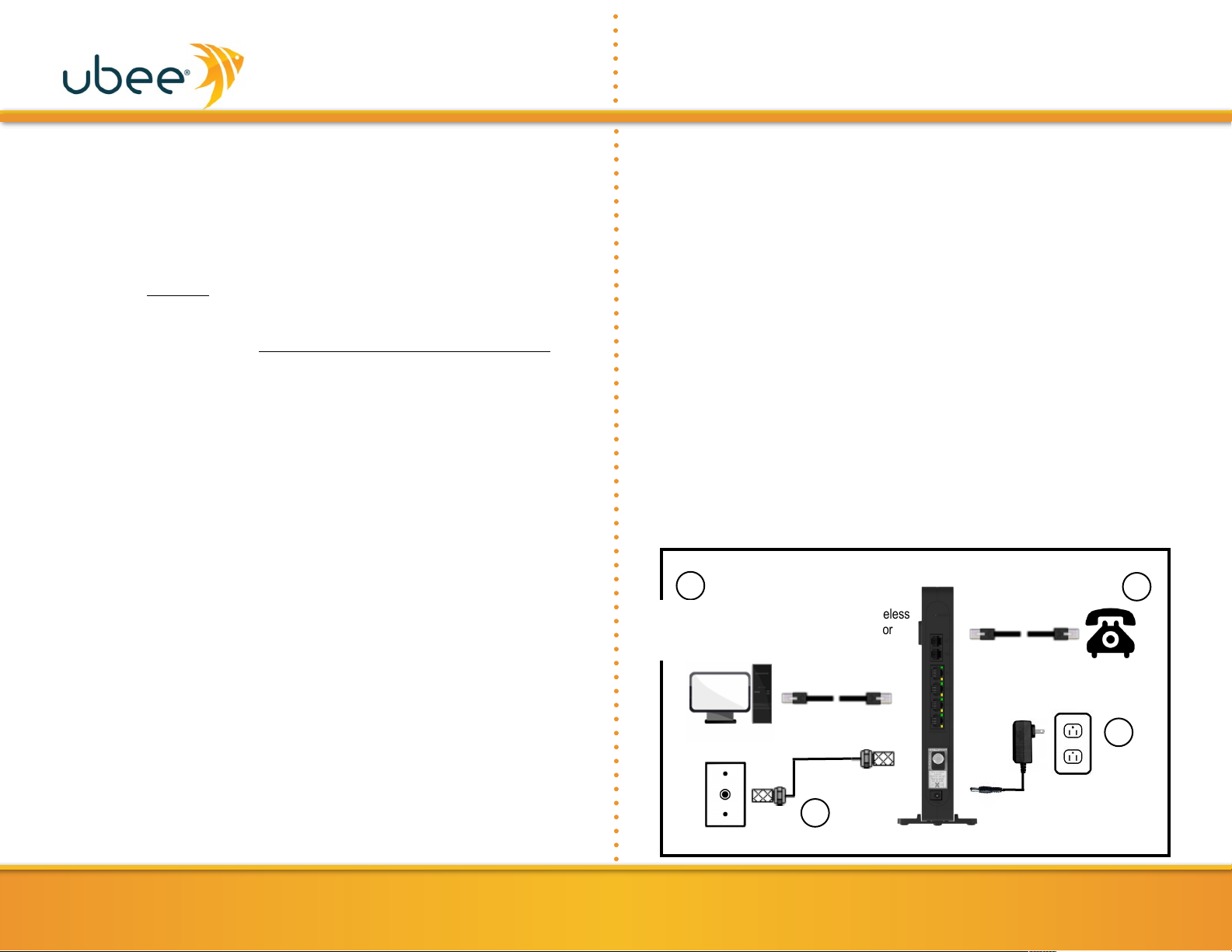
INSTALLING THE MODEM
1. Connect a coaxial cable (not supplied) to the CABLE connector
on the rear panel of the device and connect the other end to
the cable wall outlet. Do not bend or over tighten the cables, as
this may strain the connector and cause damage. To connect a
modem and a television to the same wall outlet, you must use a
cable line splitter (not included).
2. Connect the Ethernet cable (supplied) to the Ethernet port on
the back panel of the modem and connect the other end to the
Ethernet port of a PC. Use a Category 5e or Category 6
Ethernet cable with RJ-45 connectors to ensure Gigabit
Ethernet speeds (when the computer supports it).
3. Connect an RJ-11 phone cable (supplied) to the TEL1 port on
the modem (when provisioned for voice service as specified by
the service provider), and connect the other end to the phone
port of the telephone. If voice service is not provisioned
through the service provider, telephone service is not available.
4. Connect the power adapter (supplied) to the POWER port.
Connect the other end to a power outlet.
1
UBC1310BA10
RJ-45
Analog Phones
RJ-11
Cable/RF
Device must be installed
vertically to obtain optimum
wireless performance.
2
1
3
4
Connect a PC or Ethernet enabled device (wireless
switch or router). A PC should be connected for
initial device installation and configuration.
Page 3

!
•
DEVICE WALL MOUNT INSTRUCTIONS
You can mount the UBC1310BA10 on a wall using the 2 mounting
brackets on the side of the device. Two round or pan head screws
are recommended. See the figure below for measurements.
www.ubeeinteractive.com
2
UBC1310BA10 Quick Installation Guide
Label
Size in Millimeters (mm)
A
7.2 +/- 0.5
B
2.6 +/- 0.15
C
19.0 +/- 1.2
To mount the device on a wall:
1. Install the 2 screws horizontally on the wall 132 mm (5.19
inches) apart.
Note: The screws should protrude from the wall so you can fit
the device between the head of the screws and the wall. If
you install the screws in drywall, use hollow wall anchors to
ensure the unit does not pull away from the wall due to
prolonged strain from the cable and power connectors.
2. Mount the device on the wall
Page 4

!
•
UNDERSTANDING DEVICE CONNECTIONS AND
BUTTONS
Rear and front panel connections/buttons are explained below:
RESET: Use to reset the device. Take a small object like the end of
a paper clip and insert it into the RESET opening. To power cycle
the device, hold for less than 5 seconds. To reset to factory default
settings, hold for more than 5 seconds. The UBC1310BA10 will
reset and reboot. WARNING: Resetting to factory defaults will
erase ANY and ALL settings that you have made and will restore
the device to factory default settings.
TEL1-TEL2: Use to connect analog telephones to the device.
Telephone service must be enabled by your service provider.
ETHERNET 1-4: Use to connect to Ethernet-enabled devices such
as computers or gaming consoles using RJ45 Ethernet cables.
Each Ethernet port on the back panel of the device has two LEDs
to indicate its status.
When an Ethernet device is connected to the cable modem:
•
The Orange LED is lit when connected at 10/100 Mbps speeds.
•
The Green LED is lit when connected at 1000 speeds (Gigabit
Ethernet).
•
LED blinks (either Orange or Green) when data is passed
between the cable modem and the connected device.
CABLE: Use to connect to the coaxial cable from your Internet
service provider.
POWER: Use to connect to the power adapter. Plug the other end
into the wall power outlet.
WPS: Located on the front panel of the device, this button is used
for the Wi-Fi Protected Setup (WPS) method to connect a PINprotected Wi-Fi device to the cable modem.
•
BASIC MODEM INFORMATION
www.ubeeinteractive.com
3
UBC1310BA10 Quick Installation Guide
Example of Cable
RF MAC Address
40:49:0F:FD:90:11
Firmware Version
9.59.1003
Compatibility
DOCSIS 3.0/2.0/1.1/1.0 certified
PacketCable 1.5/2.0 compatible
Ethernet 10/100/1000 Mbps
Wireless 802.11a/b/g/n/ac
Local Web
User Interface
Access
http://192.168.100.1
Modem Web
Page Login (web
user interface)
Login: user
Password: user
Default
Encryption
WPA/WPA2-PSK
Wireless Default
SSIDs
“Ubee” plus the last 4 characters of the
Cable Modem MAC address (in upper
case). “-2.4G” is added for the 2.4GHz
band, and “-5G” is added for the 5GHz
band.
SSID Examples
Device with above MAC address:
2.4GHz Radio SSID = Ubee9011-2.4G
5GHz Radio SSID = Ubee9011-5G
WPA2-PSK
Wireless Key
The default key for both the 2.4 and 5GHz
radio bands is the last 10 characters of the
CM MAC address. This is your wireless
password.
Page 5
!
www.ubeeinteractive.com
4
•
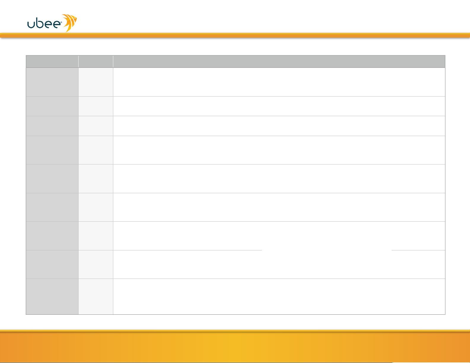
LED BEHAVIOR
LED
COLOR
DESCRIPTION
POWER
GREEN
ON - Internal power-on completed successfully.
FLASHES - Initializing.
OFF - No power supplied.
DS
(downstream)
GREEN
FLASHES - Once every second when DS scan is in progress and when a firmware upgrade is in progress.
ON - Locked to DS channels and registered with the CMTS.
US (upstream)
GREEN
FLASHES - Once every second when US scan is in progress and when a firmware upgrade is in progress.
ON - Locked to US channels and registered with the CMTS.
ONLINE
GREEN
FLASHES - Obtaining IP address and configuration file.
ON - Configuration completed successfully, network connected.
OFF - Network connect failed.
TEL1
GREEN
ON - Telephony is enabled and telephone is on-hook.
OFF - Telephony is not provisioned.
FLASHES - Call is in progress or eMTA is attempting to register.
TEL2
GREEN
ON - Telephony is enabled and telephone is on-hook.
OFF - Telephony is not provisioned.
FLASHES - Call is in progress or eMTA is attempting to register.
2.4G
GREEN
FLASHES - 2.4GHz WiFi traffic is being passed.
ON - 2.4GHz WiFi is enabled.
OFF - 2.4GHz WiFi is disabled.
5G
GREEN
FLASHES - 5GHz WiFi traffic is being passed.
ON - 5GHz WiFi is enabled.
OFF - 5GHz WiFi is disabled.
ETHERNET
1-4 (rear panel)
GREEN /
ORANGE
ON GREEN - An Ethernet device is connected to the UBC1310BA10 at 1000 Mbps speed.
ON ORANGE - An Ethernet device is connected to the UBC1310BA10 at 10/100 Mbps speeds.
FLASHES (GREEN or ORANGE) - Data is being passed between the UBC1310BA10 and the connected Ethernet
device.
✴ Please note that both the 2.4GHz and
5GHz radios are enabled by default.
UBC1310BA10 Quick Installation Guide
Page 6

•
FEDERAL COMMUNICATION COMMISSION
INTERFERENCE STATEMENT
This device complies with Part 15 of the FCC Rules. Operation is
subject to the following two conditions: (1) This device may not
cause harmful interference, and (2) this device must accept any
interference received, including interference that may cause
undesired operation.
This equipment has been tested and found to comply with the
limits for a Class B digital device, pursuant to Part 15 of the FCC
Rules. These limits are designed to provide reasonable protection
against harmful interference in a residential installation. This
equipment generates, uses and can radiate radio frequency energy
and, if not installed and used in accordance with the instructions,
may cause harmful interference to radio communications.
However, there is no guarantee that interference will not occur in a
particular installation. If this equipment does cause harmful
interference to radio or television reception, which can be
determined by turning the equipment off and on, the user is
encouraged to try to correct the interference by one of the
following measures:
• Reorient or relocate the receiving antenna.
• Increase the separation between the equipment and receiver.
• Connect the equipment into an outlet on a circuit different
from that to which the receiver is connected.
• Consult the dealer or an experienced radio/TV technician for
help.
5GHz Wireless Statement:
For operation within the 5.15~5.25GHz frequency ranges, this device is
restricted to indoor environments.
This device meets all the other requirements specified in Part 15E,
Section 15.407 of the FCC Rules.
www.ubeeinteractive.com
5
UBC1310BA10 Quick Installation Guide
FCC Caution:
Any changes or modifications not expressly approved by the party
responsible for compliance could void the user's authority to
operate this equipment.
This transmitter must not be co-located or operating in
conjunction with any other antenna or transmitter.
Radiation Exposure Statement:
This equipment complies with FCC radiation exposure limits set
forth for an uncontrolled environment. This equipment should be
installed and operated with minimum distance 30cm between the
radiator & your body.
 Loading...