

Page 1

Ubee TI D3.0 WLCM
Model Number: DDW3600
User Manual
Rev. 1.0
November 12, 2009
Page 2

◆ Important Safety Warnings
"Installation" should include bonding the screen of the coaxial cable to the earth at the building
entrance per ANSI/NFPA 70, the National Electrical Code (NEC), in particular Section 820.93,
Grounding of Outer Conductive Shield of a Coaxial Cable.
◆ Installation
Follow the procedures below to install the hardware. Figure 0 illustrates the connection
relationship.
1. Connect one end of the coaxial cable (not included) to the CABLE port on the modem, and
connect the other end to the cable wall outlet. Be sure not to bend or over tighten the cables as
this may strain the connector and cause damage. If you plan to connect the modem and
television to the same wall outlet, you must use a cable line splitter (not included).
2. Connect one end of the Ethernet cable to the ETHERNET port on the modem, and connect
the other end to the Ethernet port on the PC.
3. Connect one end of the Phone line cable to the VoIP port on the modem, and connect the
other end to the phone port of the phone set.
4. Connect one end of the DC power adapter to the POWER port on the modem, and connect
the other end to an electric outlet on the wall.
◆ Connectors on the rear panel of the Modem
This list of connectors describes where to connect the cables and power adapter when
installing the cable modem.
1. POWER: This is where you plug the included power adapter. Remember to use only the
power adapter that came with the Cable Modem.
2. GigE: This is where you plug the Ethernet cable. The other end connects to the Ethernet
port on the PC or NIC.
3. RESET button: This is what you can reset the setting to factory default by pressing button
on more than 10 seconds.
Page 3

4. CABLE Connector: This is where you connect the coaxial cable (not included) that leads to
the cable splitter (not included) or the cable wall outlet.
5. USB: This is where you plug the USB cable. The other end connects to the USB port on the
PC.
Figure 1 illustrates the connection relationship
Page 4
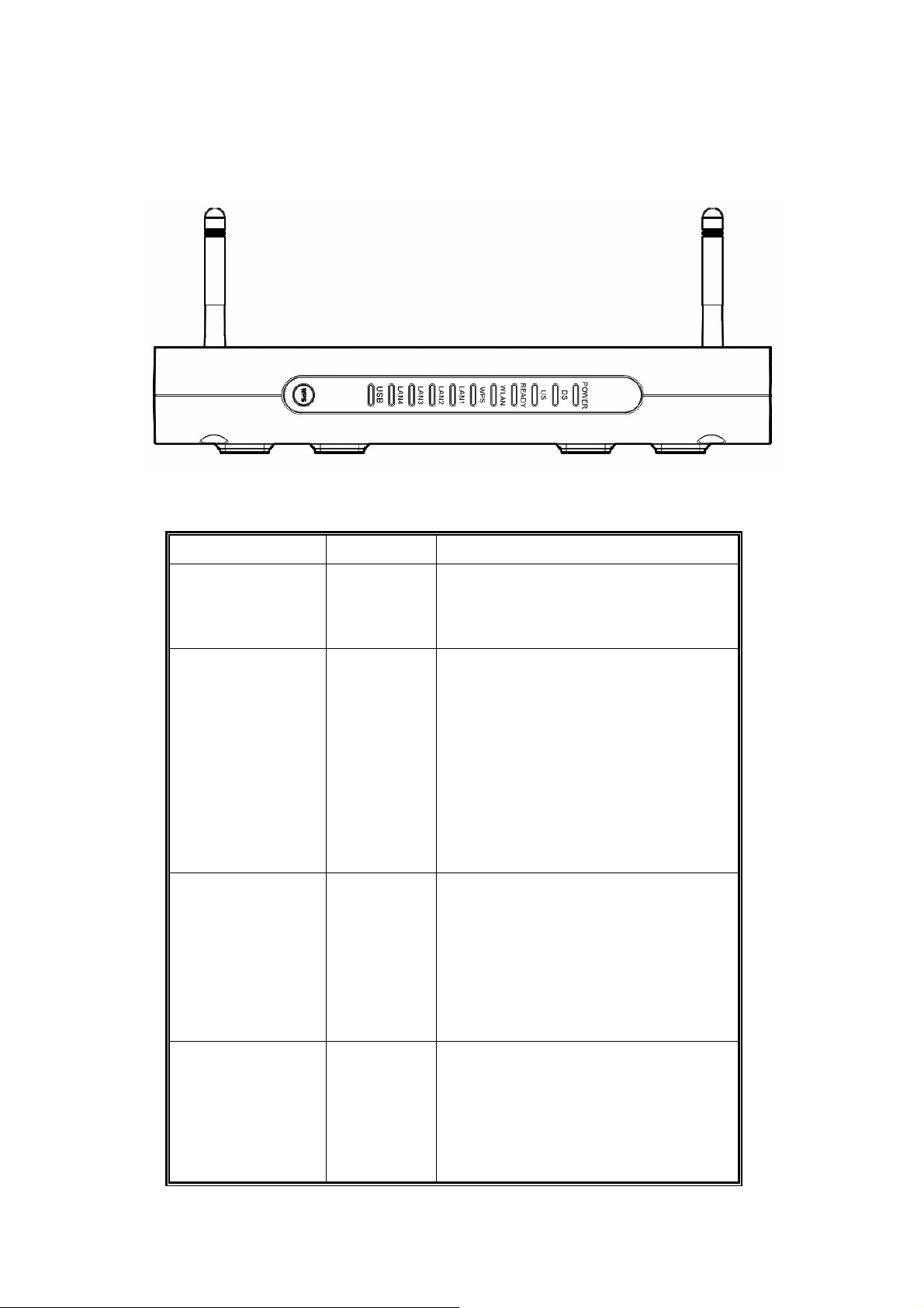
◆ LEDs on the front panel of the Modem
Please see the LED descriptions below.
LED Color DESCRIPTION
Power Green Indicates that the cable modem has
successfully completed internal power-on
tests. LED flashes if power-on fails.
DS
US Green/Orange Indicates that data is being transmitted from
Green/Orange Indicates that data is being received from
the cable network. Orange indicates more
than one Channel is bonded. Green
indicates that one Channel is bonded. Prior
to registration, DS would flash slowly to
indicate it’s looking for DS channel.
Post-registration (READY LED is lit), DS
would flash when traffic is being passed.
the cable modem to the cable network.
Orange indicates more than one Channel is
bonded. Green indicates that one Channel
is bonded. LED flash when traffic is being
passed.
Ready Green LED flashes slowly when performing
upstream ranging. LED flashes quickly
when acquiring IP Address and
Configuration File. LED must remain off if
device receives disable configuration file.
Page 5

LED must be solid once registered with
network.
WLAN Green Indicates connectivity in the WiFi port LED
flashes when traffic is being passed.
WPS Green TBD
LAN1 to LAN4 Green/Orange Indicates connectivity between the Ethernet
port on the cable modem and the PC’s
Ethernet port. LED flashes when traffic is
being passed. Green indicates GbE.
Orange indicates that 10/100/1000 is
enabled.
USB
Green Indicates connectivity in the USB port LED
flashes when traffic is being passed.
◆ Specification
Operating Environment: 40 degree C max.
DOCSIS RF Requirement Specification
Table 3. DOCSIS RF Specification
US-DOCSIS 2.0 Upstream Output
Parameter Value
Frequency 5 to 42MHz (edge to edge)
Level range (one channel) TDMA;
+8 to +54 dBmV (32QAM, 64QAM)
+8 to +55 dBmV (8QAM, 16QAM)
+8 to +58 dBmV (QPSK)
S-CDMA:
+8 to +53 dBmV (all modulation)
Modulation Type QPSK, 8QAM, 16QAM, 32QAM, 64QAM, 128QAM and 256QAM
Modulation Rate (nominal) TDMA: 160, 320, 640, 1280, 2560 and 5120 kHz
S-CDMA: 1280, 2560, and 5120 kHz
Bandwidth TDMA: 200, 400, 800, 1600, 3200 and 6400 kHz
S-CDMA: 1600, 3200 and 6400 kHz
Output Impedance 75 ohms
Output Return Loss > 6 dB (5 – 42 MHz)
Connector F connector
Page 6

US-DOCSIS 2.0 Downstream Output
Parameter Value
Center Frequency 91to 857 MHz (+/- 30 kHz)
Level Range (one channel) -15 dBmV to +15 dBmV
Modulation Type 64QAM, 256QAM and 1024QAM (Three Demodulators)
Symbol Rate (nominal) 5.056941 Msym/s ( 64QAM) and
5.360537 Msym/s (256QAM)
Bandwidth 6 MHz
Total Input Power < 30 dBmV (40-900 MHz)
Input Load Impedance 75 ohms
Input Return Loss > 6 dB (88-860 MHz)
Connector F connector
DOCSIS 3.0 Upstream Output
Parameter Value
Frequency 5 to 42 MHz (edge to edge)
Level range (one channel) TDMA/ATDMA;
+17 to +57 dBmV (32QAM, 64QAM)
+17 to + 58 dBmV (8QAM, 16QAM)
+17 to +61 dBmV (QPSK)
S-CDMA:
+17 to +56 dBmV (all modulation)
Modulation Type QPSK, 8QAM, 16QAM, 32QAM, 64QAM, 128QAM and 256QAM
Modulation Rate (nominal) TDMA: 160, 320, 640, 1280, 2560 and 5120 kHz
S-CDMA: 1280, 2560, and 5120 kHz
Bandwidth TDMA: 200, 400, 800, 1600, 3200 and 6400 kHz
SCDMA Codes per Sub
Frame 1 to 128
S-CDMA: 1600, 3200 and 6400 kHz
Output Impedance 75 ohms
Output Return Loss > 6 dB (5 – 42 MHz)
Connector F connector
US-DOCSIS 3.0 Downstream Output
Parameter Value
Center Frequency 88 to 1002 MHz (+/- 30 kHz)
Page 7

Level Range (one channel) -15 dBmV to +15 dBmV
Modulation Ty pe 64QAM, 256QAM
Symbol Rate (nominal) 5.056941 Msym/s ( 64QAM) and
5.360537 Msym/s (256QAM)
Bandwidth 6 MHz (Alpha = 0.18 @ 64QAM & 0.12 @ 256QAM)
Capture Bandwidth Supporting four channel bounding on continuous 64MHz CBW
Total Input Power < 36 dBmV
Input Load Impedance 75 ohms
Input Return Loss > 6 dB (88-1002 MHz)
Connector F connector
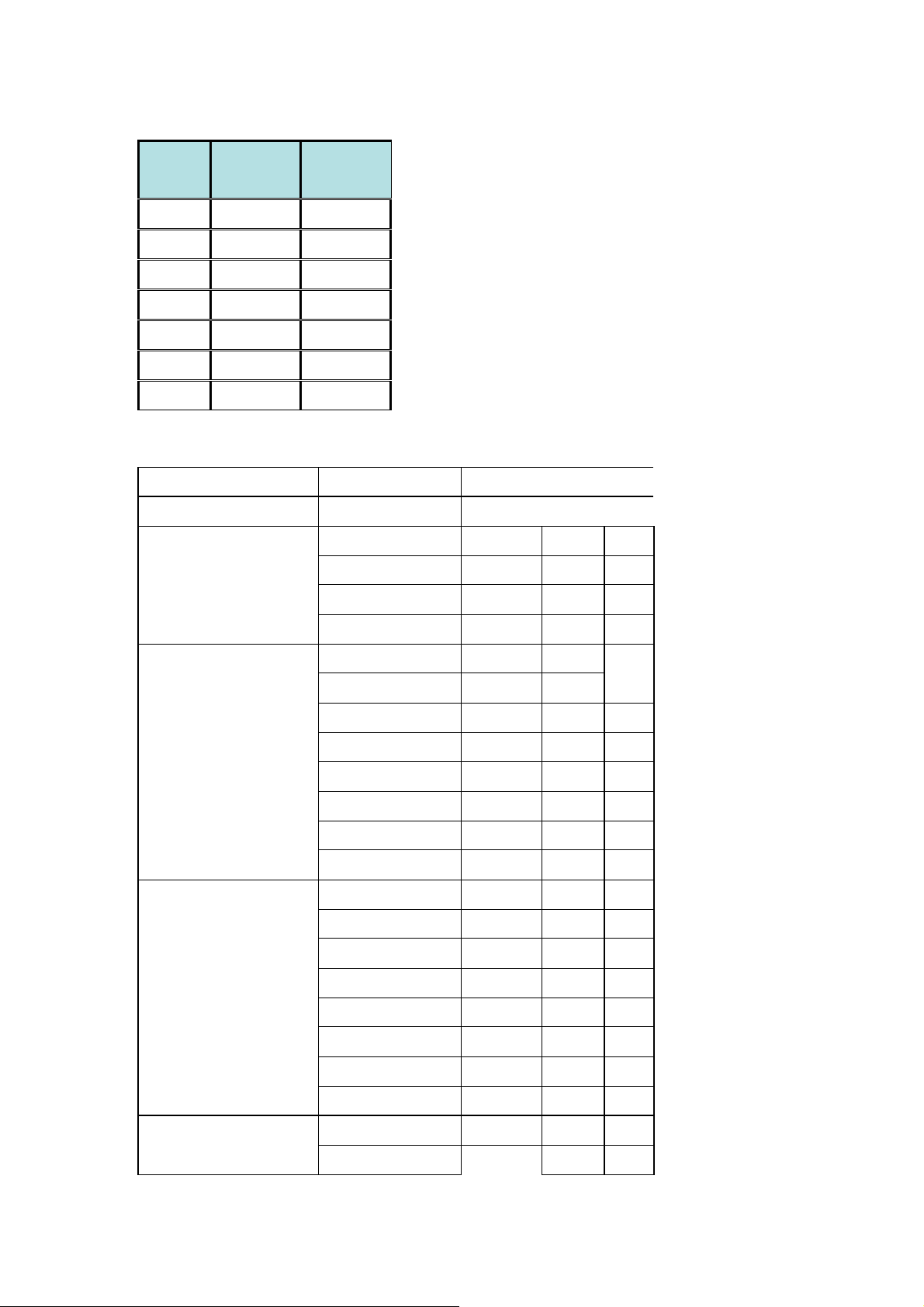
WLAN RF Requirement Specification
a) frequency rage:
2.412GHz to 2.462GHz
b)EUT frequency list:
the following frequency is point to centre frequency
1.There are 11 channel at 802.11 b/g/ n model HT20
Channel
ID
Frequency
(MHz)
FCC(USA)
1 2412 O
2 2417 O
3 2422 O
4 2427 O
5 2432 O
6 2437 O
7 2442 O
8 2447 O
9 2452 O
10 2457 O
11 2462 O
Page 8
There are 7 channel at 802.11 b/g/ n model HT40
Channel
ID
Frequency
(MHz)
FCC(USA)
3 2422 O
4 2427 O
5 2432 O
6 2437 O
7 2442 O
8 2447 O
9 2452 O
c)modulation:
Standard
(Mbps) modul. coding
DSSS-CCK
DSSS-CCK
DSSS-CCK
Data Rate
1
2
5.5
BPSK
QPSK
CCK
11b
11g
DSSS-CCK
OFDM
OFDM
OFDM
OFDM
OFDM
OFDM
OFDM
MCS8
MCS9
MCS10
MCS11
MCS12
MCS13
MCS14
11
6
9
12
18
24
36
48
54
13
29
39
52
78
104
117
CCK
BPSK
QPSK
QPSK
QPSK
16QAM
16QAM
64QAM
64QAM 3/4
BPSK 1/2
QPSK 1/2
QPSK 3/4
16QAM 1/2
16QAM 3/4
64QAM 2/3
64QAM 3/4
11n 20MHz 2 streams
MCS15
MCS8
MCS9
130
27
54
64QAM 5/6
BPSK 1/211n 40MHz 2 streams
QPSK 1/2
Page 9
MCS10
81
QPSK 3/4
MCS11
MCS12
MCS13
MCS14
MCS15
108
162
216
243
270
16QAM 1/2
16QAM 3/4
64QAM 2/3
64QAM 3/4
64QAM 5/6
Rates
Test Channels
Conditions Mode Antenna Limits
Mbps
Tx power
802.11g 1,6,11 6 @target power 20dBm 0&2
802.11g 1,6,11 36 @target power 20dBm 0&2
802.11g 1,6,11 48 @target power 19dBm 0&2
802.11b 1,6,11 @target power 19dBm 0&2
802.11n 1,6,11 MCS0/8 @target power 20dBm HT20/40 0&2
802.11n 1,6,11 MCS4/12 @target power 20dBm HT20/40 0&2
802.11n 1,6,11 MCS5/13 @target power 18dBm HT20/40 0&2
802.11n 1,6,11 MCS6/14 @target power 14dBm HT20/40 0&2
+/-2dB(ex
pect the
band
edge
power)
802.11n 1,6,11 MCS7/15 @target power 12dBm HT20/40 0&2
Rates
Test Channels
Conditions Mode Antenna Limits
Mbps
Tx Spectral Mask
802.11g 6 @+/-9MHz offset 0&2 0dBr
802.11g 6 @+/-11MHz offset 0&2 -20dBr
802.11g 6 @+/-20MHz offset 0&2 -28dBr
802.11g 6 @+/-30MHz offset 0&2 -40dBr
802.11n 6 @+/-9MHz offset HT20 0&2 0dBr
802.11n 6 @+/-11MHz offset HT20 0&2 -20dBr
802.11n 6 @+/-20MHz offset HT20 0&2 -28dBr
802.11n 6 @+/-30MHz offset HT20 0&2 -45dBr
802.11n 6 @+/-19MHz offset HT40 0&2 0dBr
802.11n 6 @+/-21MHz offset HT40 0&2 -20dBr
802.11n 6 @+/-40MHz offset HT40 0&2 -28dBr
802.11n 6 @+/-60MHz offset HT40 0&2 -45dBr
Channel Accuracy
802.11g
6
/n
@2437MHz center
0&2 +/-25ppm
frequency( 25±3℃)
Page 10
Packet Error Rate (PER)
802.11g 1,6,11
802.11n 1,6,11
802.11n 1,6,11
Receiver Sensitivity Test
802.11g 1,6,11
802.11n 1,6,11
@date rate=6,36,48,54
Mbps
@date rate=MCS0/8,
MCS5/13, MCS6/14 &
MCS7/15
PER<10% @date
rate=MCS0/8,
MCS5/13, MCS6/14 &
MCS7/15
@10% PER/1000 Byte
Pack size/48,54Mbps
@10% PER/1000 Byte
Pack size/ MCS6/14 &
MCS7/15
@10% PER/1000 Byte
0&2 <10%
HT20 0&2 <10%
HT40 0&2 <10%
0&2 <-70dBm
HT20 0&2 <-68dBm
802.11n 1,6,11
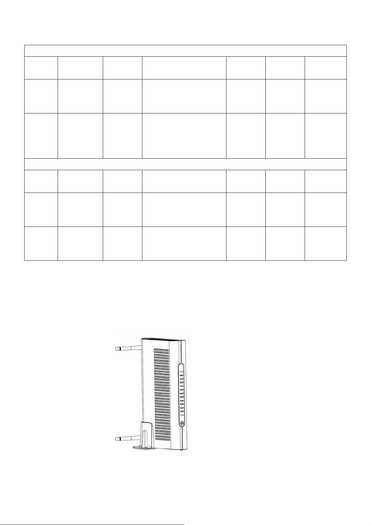
◆ Safety Notices
1. When this device is placed upright with the aid of the stand, the stand must be fixed at a 90
degree angle to the cable modem;otherwise the device will have the risk of tipping over.
Pack size/ MCS6/14 &
MCS7/15
HT40 0&2 <-63dBm
2. "Installation" should include bonding the screen of the coaxial cable to the earth at the
building entrance per ANSI/NFPA 70, the National Electrical Code (NEC), in particular
Page 11

Section 820.93; Grounding of Outer Conductive Shield of a Coaxial Cable.
3. The device is also designed for IT power system with phase to phase voltage 120V.
4. How to disconnect device. The power plug shall be installed near the cable modem and
shall be easily accessible. If abnormality happens to the cable modem, disconnect the po wer
plug from the AC wall outlet immediately."
Page 12

FCC Notice
This device complies with part 15 of the FCC Rules. Operation is subject to the
following two conditions: (1) This device may not cause harmful interference, and (2)
this device must accept any interference received, including interference that may
cause undesired operation.
Federal Communication Commission Interference Statement
This equipment has been tested and found to comply with the limits for a Class B
digital device, pursuant to Part 15 of the FCC Rules. These limits are designed to
provide reasonable protection against harmful interference in a residential installation.
This equipment generates, uses and can radiate radio frequency energy and, if not
installed and used in accordance with the instructions, may cause harmful interference
to radio communications. However, there is no guarantee that interference will not
occur in a particular installation. If this equipment does cause harmful interference to
radio or television reception, which can be determined by turning the equipment off
and on, the user is encouraged to try to correct the interference by one of the
following measures:
- Reorient or relocate the receiving antenna.
- Increase the separation between the equipment and receiver.
- Connect the equipment into an outlet on a circuit different from that to which the
receiver is connected.
- Consult the dealer or an experienced radio/TV technician for help.
THE MANUFACTURER IS NOT RESPONSIBLE FOR ANY RADIO OR TV
INTERFERENCE CAUSED BY UNAUTHORIZED MODIFICATIONS TO THIS
EQUIPMENT. SUCH MODIFICATIONS COULD VOID THE USER’S
AUTHORITY TO OPERATE THE EQUIPMENT.
To comply with FCC RF exposure compliance requirements, a separation distance of
at least 20 cm must be maintained between the antenna of this device and all persons.
This transmitter must not be co-located or operating in conjunction with any other
antenna or transmitter.
10
 Loading...