

Page 1

DDW262 D2.0 WLCM model and
Router Safety and Installation
Product Insert
i Federal Communications Commission
(FCC) Interference Statement
This device has been tested and found to comply
with the limits for a Class B digital device, pursuant
to Part 15 of the FCC Rules. These limits are
designed to provide reasonable protection against
harmful interference in a residential installation. This
device generates, uses, and can radiate radio
frequency energy. If not installed and used in
accordance with the instructions, the device may
cause harmful interference to radio communications.
There is no guarantee, however, that interference
will not occur in a particular installation. If this device
causes harmful interference to radio or television
reception, which can be determined by turning it off
and on, the user can try to correct the interference
by one of the following measures:
噝 Increase the separation between the device and
the equipment with which it is interfering (for
example, a television or radio).
噝 Connect the device into an electrical outlet on a
different circuit than the interfered device is
connected.
噝 Consult the dealer or an experienced radio/TV
technician for help.
i FCC Regulatory Information
This device complies with Part 15 of the FCC Rules.
Operation is subject to the following two conditions:
(1) This device may not cause harmful interference,
and (2) this device must accept any interference
received, including interference that may cause
undesired operation. (3) There are two statements
for this product:
i FCC Radiation Exposure Statementʳ
噝This device complies with FCC radiation exposure
limits set forth for an uncontrolled environment.
噝This device should be installed and operated at a
minimum distance of 20cm between itself and
your body.
噝This device must not be co-located or operating in
conjunction with any other antenna or transmitter.
i Safety Notices
1. Grounding: Install the device to include
grounding the coaxial cable to the earth at the
building entrance per ANSI/NFPA 70 and the
National Electrical Code (NEC, in particular,
Section 820.93, Grounding of the Outer
Conductive Shield of a Coaxial Cable).
2. Disconnecting: If the device becomes damaged
or encounters some other abnormality,
disconnect the power plug from the wall outlet
immediately.
3.Installing: Install the device in a location not to
exceed the maximum temperature of 40 degrees
Celsius (104 degrees Fahrenheit).
4.Mounting: When this device is placed upright
with the aid of the stand, fix the stand at a
90-degree angle to the device. Otherwise, the
2. Connect one end of the supplied Ethernet cable
to one of the ethernet ports on the device.
Connect the other end to the Ethernet port on a
PC. Note: Use Category 5e or Category 6
Ethernet cables with RJ45 connectors to connect
Ethernet devices to the ethernet ports. This
ensures Ethernet speeds (unless the computer
does not support it).
3. Connect one end of the power adapter to the
power port on the device. Connect the other end
to an electric outlet. Important: Use only the
power adapter that is shipped with the
FCC Caution: Any changes or modifications not
expressly approved by the party responsible for
compliance could void the user's authority to
operate this device.
IEEE 802.11b or 802.11g or 802.11n operation of
this device in the U.S.A. is firmware-limited to
channels 1 through 11.
device may tip over. Refer to Figure 1.
Figure 1: Device Stand at 90 Degree Angle
i Installation
Follow these procedures to install the device. Refer
to Figure 2.
1. Connect one end of a coaxial cable (not included)
to the cable port on the device. Connect the other
end to the cable wall outlet or a cable splitter (not
included). Do not bend or over-tighten the cables
as this may strain the connector and cause
damage. If you plan to connect the device and a
television to the same cable wall outlet, you must
use a cable line splitter (not included).
i
Rear Panel Connections and Other
Information
Following are descriptions of the rear panel
connections. Refer to Figure 2.
噝 power: Connect the power adapter. Only use the
power adapter provided with the device.
device. Press for more than 10 seconds to reset
the device to the factory defaults.
噝 ethernet 1 to 4: Connect the Ethernet RJ45
cable. Connect the other to the Ethernet port on
the PC or NIC.
噝 cable: Connect the coaxial cable (not included)
噝 reset: Insert a pointed object into the opening.
Press for less than10 seconds to power cycle the
that comes from the cable wall outlet or cable
splitter (not included) to the cable connector on
the back of the device.
噝 WPS: Use the Wi-Fi Protected Setup found on
top of the device to connect PIN-protected Wi-Fi
equipment to this device. Refer to the user guide
for more information.
Figure 2: Rear Panel Connections
i LED Descriptions and Behaviors
Following are the descriptions and behaviors of the
LEDs on the front of the device. Refer to Figure 3
1
2 3
device.
Page 2
LED COLOR DESCRIPTION
POWER Green On–Device has successfull
y
completed internal
power on tests. BLINKS i
f
ϋ
power on self test failsϋ
SYNCH Green Indicates the connection
status between the device
and the cable network.
The LED is lit when the
device has established a DS
channel with MSO’s CMTS
(Cable Modem Termination
Equipment)
The LED will flash during
registration process network
Blinks quickly–Acquiring IP
address and configuration
file.
Off–Device receives disable
configuration file message.
WLAN Green On–At least one wireless
client is linked to the device.
Blinks–Indicates modem
traffic.
Off–No wireless clients
connected.
WPS Green On–WPS used.
Off–WPS not used.
ETHERNET
1,2,3,4
Green
or
Orange
On–Connectivity between
Ethernet ports on the device
and computer:
- Green – 100Mbps
- Orange – 10Mbps
Blinks–Sending or receiving
data.
Note: Sync and Ready LEDs blink during a firmware
upgrade.
Figure 3: Front Panel LEDs
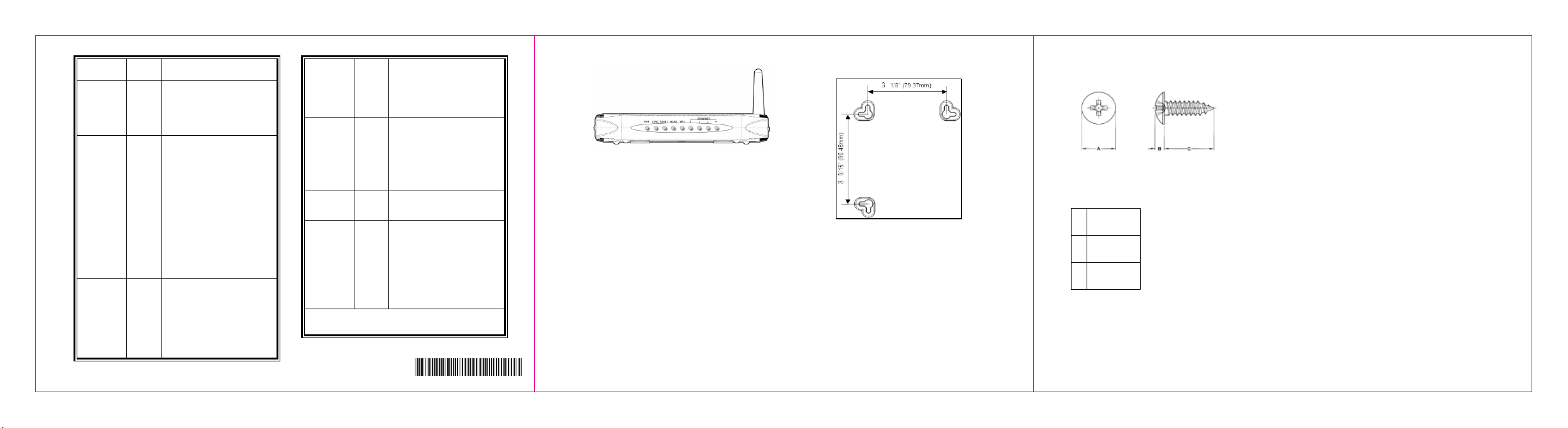
i Wall Mount Installation
You can mount the device on a wall using the
mounting brackets on the bottom of the device.
Refer to Figure 4. It is recommended to use two
round or pan head screws, not included, as
shown in Figures 5 and 6.
1. Install two screws horizontally apart on a wall
using the measurements shown in Figure 4.
Ensure the screws protrude from the wall to fit the
device between the head of the screw and the
wall. If the screws are installed in drywall, use
hollow wall anchors to ensure the unit does not
pull away from the wall due to prolonged strain
from the cable and power connectors.
Figure 4: Mounting bracket measurements
2. Remove the device from the product package.
3. Mount the device on the wall.
Ready Green On–Ranging registration
process is successful and the
device is ready to send and
receive data.
Blinks slowly–Performing
upstream ranging.
Figure 5: Bracket distances
A 6.65+/-0.35
B 1.9+/-0.15
C 19.0+/ 1.20
Figure 6: Screw sizes
4
5
6
540. 00776. 005
-
 Loading...