

Ubee DDW3610, DVW3102B, EWV3200, U10C022 User Manual
Ubee DDW3612 Wireless
Cable Modem Gateway
Firmware Version: 8.9.1002
Subscriber User Guide
version 10/14/10
www.ubeeinteractive.com
8085 S. Chester Street, Suite 200
Englewood, CO 80112
1.888.390.8233
Sales (email): amsales@ubeeinteractive.com
Support (email) amsupport@ubeeinteractive.com
Notices and Copyrights
Copyright ©Ubee 2010. All Rights Reserved. This document contains proprietary information of Ubee and is not to be disclosed or used
except in accordance with applicable agreements. This material is protected by the copyright laws of the United States and other
countries. It may not be reproduced, distributed, or altered in any fashion by any entity (either internal or external to Ubee), except in
accordance with applicable agreements, contracts, or licensing, without the express written consent of Ubee and the business
management owner of the material.
This device is Wifi Alliance Certified:

Contents
1 Introduction. . . . . . . . . . . . . . . . . . . . . . . . . . . . . . . . . . . . . . . . . . . . . . . . . . . . . . . . 1
1.1 Device Overview . . . . . . . . . . . . . . . . . . . . . . . . . . . . . . . . . . . . . . . . . . . . . . . . . . . . 1
1.1.1 Application Diagram . . . . . . . . . . . . . . . . . . . . . . . . . . . . . . . . . . . . . . . . . . . . 2
1.1.2 Physical Specifications, Standards, Firmware Operations. . . . . . . . . . . . . . . 2
1.1.3 Default Values . . . . . . . . . . . . . . . . . . . . . . . . . . . . . . . . . . . . . . . . . . . . . . . . 4
1.1.4 LED Operational Summary . . . . . . . . . . . . . . . . . . . . . . . . . . . . . . . . . . . . . . 5
2 Installation Instructions . . . . . . . . . . . . . . . . . . . . . . . . . . . . . . . . . . . . . . . . . . . . . . 7
2.1 Complete Prerequisite Tasks/Connect the Device. . . . . . . . . . . . . . . . . . . . . . . . . . . 7
2.2 Access the Web Interface . . . . . . . . . . . . . . . . . . . . . . . . . . . . . . . . . . . . . . . . . . . . . 7
2.3 Validate Connectivity/Connect Devices to the Network . . . . . . . . . . . . . . . . . . . . . . 10
2.3.1 Connect/Validate Wireless Clients . . . . . . . . . . . . . . . . . . . . . . . . . . . . . . . . 10
2.3.2 Additional Troubleshooting Information . . . . . . . . . . . . . . . . . . . . . . . . . . . . 11
3 Web User Interface Instructions . . . . . . . . . . . . . . . . . . . . . . . . . . . . . . . . . . . . . . 12
3.1 Cable Modem - Information . . . . . . . . . . . . . . . . . . . . . . . . . . . . . . . . . . . . . . . . . . . 12
3.2 Cable Modem - Status . . . . . . . . . . . . . . . . . . . . . . . . . . . . . . . . . . . . . . . . . . . . . . . 13
3.3 Cable Modem - Downstream . . . . . . . . . . . . . . . . . . . . . . . . . . . . . . . . . . . . . . . . . . 14
3.4 Cable Modem - Upstream . . . . . . . . . . . . . . . . . . . . . . . . . . . . . . . . . . . . . . . . . . . . 15
3.5 Cable Modem - Operation Config . . . . . . . . . . . . . . . . . . . . . . . . . . . . . . . . . . . . . . 16
3.6 Cable Modem - Event Log . . . . . . . . . . . . . . . . . . . . . . . . . . . . . . . . . . . . . . . . . . . . 18
3.7 Gateway . . . . . . . . . . . . . . . . . . . . . . . . . . . . . . . . . . . . . . . . . . . . . . . . . . . . . . . . . . 19
3.7.1 Gateway - Information . . . . . . . . . . . . . . . . . . . . . . . . . . . . . . . . . . . . . . . . . 19
3.7.2 Gateway - Setup. . . . . . . . . . . . . . . . . . . . . . . . . . . . . . . . . . . . . . . . . . . . . . 21
3.7.3 Gateway - DHCP . . . . . . . . . . . . . . . . . . . . . . . . . . . . . . . . . . . . . . . . . . . . . 22
3.7.4 Gateway - Static Lease . . . . . . . . . . . . . . . . . . . . . . . . . . . . . . . . . . . . . . . . 24
3.7.5 Gateway - DDNS . . . . . . . . . . . . . . . . . . . . . . . . . . . . . . . . . . . . . . . . . . . . . 25
3.7.6 Gateway - Time . . . . . . . . . . . . . . . . . . . . . . . . . . . . . . . . . . . . . . . . . . . . . . 26
3.7.7 Gateway - Options . . . . . . . . . . . . . . . . . . . . . . . . . . . . . . . . . . . . . . . . . . . . 27
3.7.8 Gateway - Mac Filtering . . . . . . . . . . . . . . . . . . . . . . . . . . . . . . . . . . . . . . . . 28
3.7.9 Gateway - IP Filtering. . . . . . . . . . . . . . . . . . . . . . . . . . . . . . . . . . . . . . . . . . 29
3.7.10 Gateway - Port Filtering . . . . . . . . . . . . . . . . . . . . . . . . . . . . . . . . . . . . . . . . 30
3.7.11 Gateway - Forwarding . . . . . . . . . . . . . . . . . . . . . . . . . . . . . . . . . . . . . . . . . 31
3.7.12 Gateway - Port Triggering . . . . . . . . . . . . . . . . . . . . . . . . . . . . . . . . . . . . . . 34
3.7.13 Additional Information - Port Triggering . . . . . . . . . . . . . . . . . . . . . . . . . . . . 35
3.7.14 Gateway - Pass Through . . . . . . . . . . . . . . . . . . . . . . . . . . . . . . . . . . . . . . . 36
3.7.15 Gateway - DMZ Host . . . . . . . . . . . . . . . . . . . . . . . . . . . . . . . . . . . . . . . . . . 37
3.8 Wireless . . . . . . . . . . . . . . . . . . . . . . . . . . . . . . . . . . . . . . . . . . . . . . . . . . . . . . . . . . 39
3.8.1 Wireless - Radio . . . . . . . . . . . . . . . . . . . . . . . . . . . . . . . . . . . . . . . . . . . . . . 39
3.8.2 Wireless - Primary Network . . . . . . . . . . . . . . . . . . . . . . . . . . . . . . . . . . . . . 41
3.8.3 Wireless - Access Control . . . . . . . . . . . . . . . . . . . . . . . . . . . . . . . . . . . . . . 44
3.8.4 Wireless - Advanced . . . . . . . . . . . . . . . . . . . . . . . . . . . . . . . . . . . . . . . . . . 45
3.8.5 Wireless - Bridging . . . . . . . . . . . . . . . . . . . . . . . . . . . . . . . . . . . . . . . . . . . . 48
3.8.6 Wireless - Wifi Multimedia . . . . . . . . . . . . . . . . . . . . . . . . . . . . . . . . . . . . . . 49
DDW3612 Subscriber User Guide • July, 2010 i

Ubee Interactive
3.8.7 Additional Information - WiFi MultiMedia (WMM) . . . . . . . . . . . . . . . . . . . . . 50
3.9 Wireless Network Deployment and Troubleshooting . . . . . . . . . . . . . . . . . . . . . . . . 52
3.9.1 Wireless Speeds and Performance . . . . . . . . . . . . . . . . . . . . . . . . . . . . . . . 52
3.10 Parental Control . . . . . . . . . . . . . . . . . . . . . . . . . . . . . . . . . . . . . . . . . . . . . . . . . . . . 57
3.10.1 Parental Control - User Setup . . . . . . . . . . . . . . . . . . . . . . . . . . . . . . . . . . . 57
3.10.2 Parental Control - Basic Settings . . . . . . . . . . . . . . . . . . . . . . . . . . . . . . . . . 59
3.10.3 Parental Control - Tod Filter . . . . . . . . . . . . . . . . . . . . . . . . . . . . . . . . . . . . . 60
3.10.4 Parental Control - Event Log . . . . . . . . . . . . . . . . . . . . . . . . . . . . . . . . . . . . 61
3.11 Tools . . . . . . . . . . . . . . . . . . . . . . . . . . . . . . . . . . . . . . . . . . . . . . . . . . . . . . . . . . . . 62
3.11.1 Tools - Ping . . . . . . . . . . . . . . . . . . . . . . . . . . . . . . . . . . . . . . . . . . . . . . . . . 62
3.11.2 Tools - Trace Route . . . . . . . . . . . . . . . . . . . . . . . . . . . . . . . . . . . . . . . . . . . 63
3.11.3 Tools - Client List . . . . . . . . . . . . . . . . . . . . . . . . . . . . . . . . . . . . . . . . . . . . . 64
3.11.4 Tools - Password . . . . . . . . . . . . . . . . . . . . . . . . . . . . . . . . . . . . . . . . . . . . . 65
3.11.5 Tools - Factory Default . . . . . . . . . . . . . . . . . . . . . . . . . . . . . . . . . . . . . . . . . 66
ii DDW3612 Subscriber User Guide • July, 2010

1 Introduction
Welcome to the Ubee family of data networking products. This guide is specific to the
DDW3612 Wireless Cable Modem Gateway. This document serves the following
purposes:
To define all relevant device compliance standards and physical specifications.
To provide user level instructions and explain device features.
To provide installation instructions and troublehsooting information.
1.1 Device Overview
This section contains the following subsections:
Application Diagram (p. 2).
Physical Specifications, Standards, Firmware Operations (p. 2).
Default Values (p. 4).
LED Operational Summary (p. 5).
Note: Some features described in this document may not be fully tested and
supported in your specific firmware release version. Where possible, features
supported only by specific versions are indicated in this document. See the
Release Notes/Letter of Operational Considerations accompanying your firmware
for further details.
DDW3612 Subscriber User Guide • July, 2010 1
1.1 Device Overview Ubee Interactive
Desktop PCs,
Router, Hub
WiFi Phone
Laptop PCs (Wireless
Connection)
Cable
Up to 4 Ethernet
LAN Connections
Ubee DDW3612
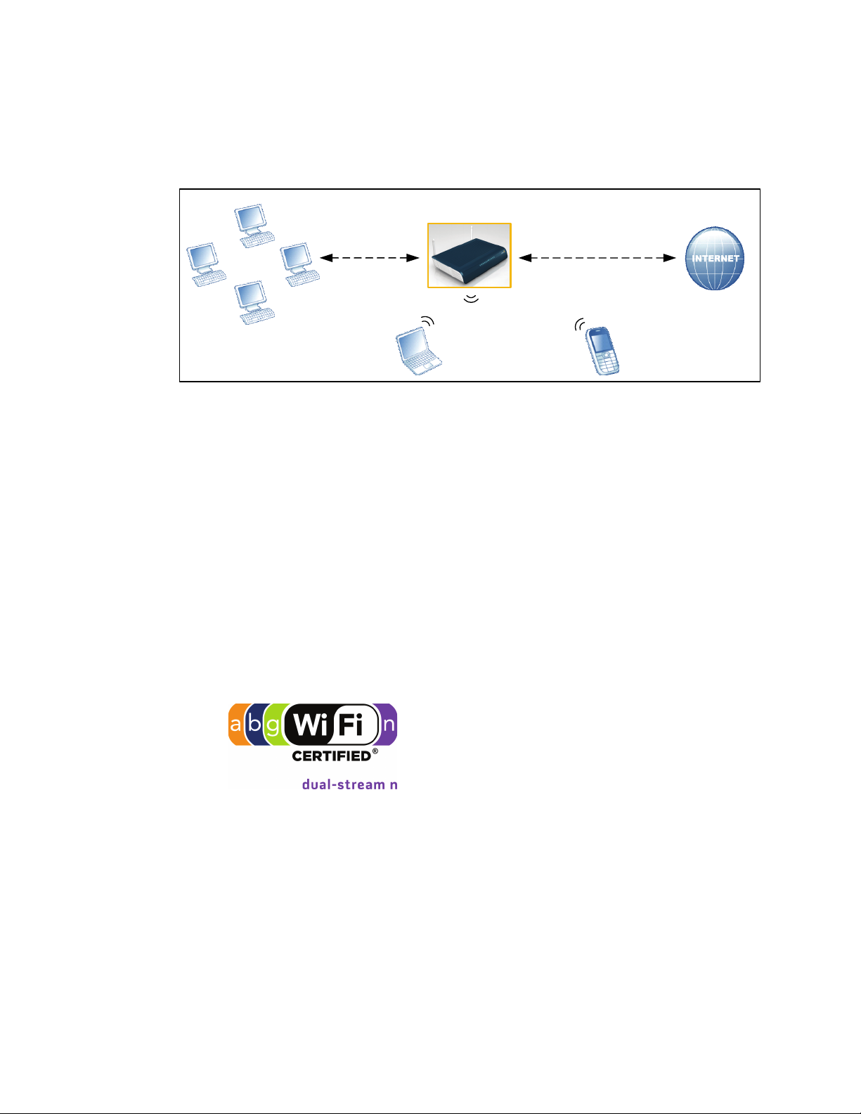
1.1.1 Application Diagram
The following graphic depicts the general connection topology and use of the
DDW3612.
1.1.2 Physical Specifications, Standards, Firmware Operations
The following list provides the features and specifications of the DDW3612 Wireless
Cable Modem Gateway.
Interfaces
Cable: F-Connector, Female
LAN: 4 10/100/1000 Mbps RJ-45 Ports
USB: 1 USB 2.0 Port
Standards/Certifications
DOCSIS 3.0/Euro DOCSIS 3.0 Certified
DOCSIS/Euro DOCSIS 1.0/1.1/2.0 Certified
CE/ FCC Class B
Downstream*
Maximum Data Rate per Channel (up to 8 channels):
DOCSIS = 30 Mbps (64 QAM), 42 Mbps (256 QAM), EuroDOCSIS = 41 Mbps
(64 QAM), 55 Mbps (256 QAM)
Total Max Bandwidth (8 Channels): DOCSIS = 343 (304) Mbps,
EuroDOCSIS 444 (400) Mbps
Symbol Rate: 6952 Ksps
2 DDW3612 Subscriber User Guide • July, 2010

Ubee Interactive 1.1 Device Overview
RF Input Power: -15 to +15dBmV (64 QAM), -15 to +15dBmV (256 QAM)
Input Impedance: 75 Ω
Upstream*
Frequency Range: 5MHz ~ 65MHz
Modulation A-TDMA: QPSK, 8, 16, 32, 64QAM, S-CMDA: QPSK, 8, 16, 32, 64,
128QAM
Max B/W of 4 Channels = 122.88 (108) Mbps, B/W Per Channel (up to 4
channels) = [QPSK 0.32 ~ 10.24 Mbps, 8 QAM 0.48 ~ 15.36 Mbps,
16 QAM 0.64 ~ 20.48 Mbps, 32 QAM 0.80 ~ 25.60 Mbps,
64 QAM 0.96 ~ 30.72 Mbps, 128 QAM/TCM 30.72 Mbps]
Symbol Rate: 160, 320, 640, 1280, 2560, 5120 Ksps
RF Output Power: TDMA/ATDMA: +8dBmV to +54dBmV (32/64 QAM). ATDMA
Only: +8dBmV to +55dBmV (8/16 QAM), +8dBmV to +58dBmV (QPSK). SCDMA: +8dBmV to +53dBmV (all modulations)
*Actual speeds can vary based on factors including network configuration and speed.
Security
VPN Pass-Through (IPSec/L2TP/PPTP)
NAT Firewall, MAC/IP/Port Filtering, Parental Control
Stateful Packet Inspection (SPI), DoS Attack Protection
WPS/ WPA/ WPA2/ WPA-PSK& 64/128-bit WEP Encryption
TACACS or RADIUS Authentication
Wireless and Network
Supports 4 SSIDs, 802.11b/g/n compliant with speeds up to 300 Mbps
DHCP Client/Server / Static IP network assignment
RIPv1/ v2
Ethernet 10/100/1000 BaseT / full-duplex auto-negotiate functionality, IPv4 to
IPv6 support.
Device Management
Customer premises equipment (CPE)
Supports IEEE 802.11e Wi-Fi Multimedia (WMM) and UAPSD (power savings)
Web-Based Configuration
Telnet Remote Management
Secure Firmware Upgrade via TFTP
Configuration Backup and Restore
SNMP Support
Interoperability with main CMTS products
Physical and Environmental
Dimensions: 172.2(W) x 254(D) x 42(H) mm
Weight: 500 g
Power: 12V/1.5A
DDW3612 Subscriber User Guide • July, 2010 3

1.1 Device Overview Ubee Interactive
Operating Temperature: 0°C ~ 40°C
Humidity: 5~90% (non-condensing)
1.1.3 Default Values
This device is pre-configured with the following parameters:
Local Port Address: 192.168.0.1, Web Interface: http://192.168.0.1
Operation Mode: NAT Mode (WAN setting)
Subnet Mask: 255.255.255.0
Wireless Defaults:
Primary SSID (subscriber-managed) = DDW3612 plus last 2 characters of the
cable modem’s MAC Address (UPPER case, if letters).
Example: DDW3612BE
Note: If the subscriber changes the SSID, the device does not revert to this default
SSID upon any reset of the device, except in the case of a manual reset to restore
factory default settings. The device MAC address can be found on the device
label, or refer to Cable Modem - Information (p. 12).
WPA Pre-shared Key = DDW3612 plus the last 6 characters (3 octets) of the
cable modem’s MAC address.
Example: DDW36127CD4BE
WPS PIN = 12345670
Device Name = UbeeAP
Web Interface Logins (also used for telnet access):
Standard User/Consumer Web Interface Login:
Username: user
Password: user
4 DDW3612 Subscriber User Guide • July, 2010

Ubee Interactive 1.1 Device Overview
1.1.4 LED Operational Summary
The following table describes what the device LEDs indicate.
LED
Position
LED
Color
LED
Label:
CM
Initialization
CM
Operation
LED1 LED2 LED3 LED4 LED5 LED6 LED7 LED8 LED9 LED10 LED11
Green Green/
USB
Host
1 Power ON On On On On On Off Off On On On On
2 Load Image Off On, if
3 H/W Check Off On, if
4 DS Locked
and
Sync OK
5 US Ranging Off On, if
6 US Ranging OKOff On, if
7 Registration OKOff On, if
8 NACO Enable
(network
access)
9NACO
Disable
1 Attached CPE On Green On
Off On, if
Off On, if
Off On, if
Blue
Eth-4 Eth-3 Eth-2 Eth-1 WPS Wi-Fi Online US DS Power
connects
connects
connects
connects
connects
connects
connects
connects
Green, if
connect,
Blue if
speed
linked at
1000 mbps
(gibabit
ethernet)
Green/
Blue
On, if
connects
On, if
connects
On, if
connects
On, if
connects
On, if
connects
On, if
connects
On, if
connects
On, if
connects
On, if
connect,
Blue
(same as
explained
to left).
Green/
Blue
On, if
connects
On, if
connects
On, if
connects
On, if
connects
On, if
connects
On, if
connects
On, if
connects
On, if
connects
On, if
connects,
Blue
(same as
explained
to left).
Green/
Blue
On, if
connects
On, if
connects
On, if
connects
On, if
connects
On, if
connects
On, if
connects
On, if
connects
On, if
connects
On, if
connects,
Blue
(same as
explained
to left).
Green Green Green Green/
Off Off Off Off Off Off
Off On Flash Flash Flash On
Off On Flash Flash 1) On, Blue
Off On Flash Flash 1) On, Blue
Off On Flash 1) On, Blue
Off On On 1) On, Blue
Off On On 1) On, Blue
Off On Off 1) On, Blue
On On On 1) On, Blue
Blue
with channel
bonding
2) On, Green
without channel
bonding
with channel
bonding
2) On, Green
without channel
bonding
with channel
bonding
2) On, Green
without channel
bonding
with channel
bonding
2) On, Green
without channel
bonding
with channel
bonding
2) On, Green
without channel
bonding
Green/
Blue
with channel
bonding
2) On, Green
without channel
bonding
with channel
bonding
2) On, Green
without channel
bonding
1) On, Blue
with channel
bonding
2) On, Green
without channel
bonding
1) On, Blue
with channel
bonding
2) On, Green
without channel
bonding
1) On, Blue
with channel
bonding
2) On, Green
without channel
bonding
1) On, Blue
with channel
bonding
2) On, Green
without channel
bonding
1) On, Blue
with channel
bonding
2) On, Green
without channel
bonding
Green
On
On
On
On
On
On
On
2 CPE Data
Tx/Rx
Flash Flash, if
connects
Flash, if
connects
Flash, if
connects
Flash Flash On 1) On, Blue
with channel
bonding
2) On, Green
without channel
bonding
1) On, Blue
with channel
bonding
2) On, Green
without channel
bonding
On
DDW3612 Subscriber User Guide • July, 2010 5

1.1 Device Overview Ubee Interactive
6 DDW3612 Subscriber User Guide • July, 2010

2 Installation Instructions
This chapter explains how to setup the device and access the web interface for the
DDW3612 Wireless Cable Modem Gateway.
2.1 Complete Prerequisite Tasks/Connect the Device
Complete the following tasks to install the DDW3612 Wireless Cable Modem Gateway
and access the web interface.
Important: Subscribers must contact their service provider to enable internet
access. Typically, the service provider initially connects and configures the device.
These steps are also provided below. If you wish to confirm the setup, or add
devices to your network, refer to “Validate Connectivity/Connect Devices to the
Network” on page 10.
Remove all contents from the device packaging.
Have a Windows PC available and powered on. The Windows PC must have an
ethernet network adapter/ethernet port. The PC must also have an internet
browser installed (Netscape or Internet Explorer).
Connect the power adapter that is included with the product package to the
DDW3612 Wireless Cable Modem Gateway and to the power outlet. Do not use
any other power adapter except the one included with the product package.
Connect a coaxial cable to the cable wall outlet. Connect the other end to the
Cable/RF port on the back of the cable modem.
Connect one end of a network cable to your computer’s Ethernet port. Connect the
other end to one of the LAN ports on the cable modem.
2.2 Access the Web Interface
Use the following procedure to access the web interface using Internet Explorer from
a Windows computer.
1. From the computer, launch an internet browser (Internet Explorer or Netscape).
2. In the internet browser, enter the following address and press <Enter/Return>:
http://192.168.0.1
DDW3612 Subscriber User Guide • July, 2010 7
2.2 Access the Web Interface Ubee Interactive
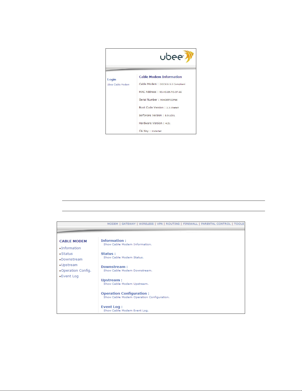
3. The Cable Modem Information Screen displays key information about the device.
4. Click Ubee Cable Modem under Login to the left side of the screen to access the
web interface.
5. At the login window, enter the user credentials:
Standard User/Consumer - Web Interface Login:
Username: user
Password: user
6. Click OK and the web interface is displayed.
Note: The username and password must be entered in lower case letters.
7. Accessing the web interface is an initial way to validate the installation. No extra
steps are required at this point for a basic LAN and/or wireless network.
8. Proceed to page 10 to test network connectivity and/or to add both Ethernet LAN
8 DDW3612 Subscriber User Guide • July, 2010

Ubee Interactive 2.2 Access the Web Interface
devices and wireless devices to the network.
Note: The web interface allows you to customize the configurations and
capabilities the device. For full explanation of all web interface functions, refer to
page 12.
DDW3612 Subscriber User Guide • July, 2010 9

2.3 Validate Connectivity/Connect Devices to the Network Ubee Interactive
2.3 Validate Connectivity/Connect Devices to the Network
To confirm network/internet operations, or to connect an Ethernet device to the
network (for example, a computer, gaming console, etc.), do the following:
1. Make sure the Ethernet device (computer, gaming console) to add to the network
is connected to the cable modem and powered on. Refer to page 7, if needed.
2. Use the device LEDs to confirm operations. The PWR, DS, US, Online, and Wifi
LEDs are solidly lit in normal operations, as is the LAN LEDs that have devices
connected to their associated ports. Refer to “LED Operational Summary” on
page 5 for more detailed information.
3. Open a web browser and go to any web site to validate network connectivity
(for example, http://www.wikipedia.org).
4. If the connected device is a gaming console, perform any online task supported by
the console (for example, log into gaming server, play online game, download
content, etc.).
5. Refer to page 11 for troubleshooting information if needed.
2.3.1 Connect/Validate Wireless Clients
To confirm operations or to connect wireless devices to the network (for example, a
laptop computer), do the following:
1. Use the device LEDs to confirm operations. The WiFi LED must be solidly lit. The
PWR, DS, US, and Online LEDs are also solidly lit in normal operations. Refer to
“LED Operational Summary” on page 5 for more detailed information.
2. Connect a wireless device to the cable modem (for example, a laptop computer).
Use the following steps:
Access the wireless networking feature on your wireless device. On a
Windows computer, for example, double-click the Wireless Networking icon in
the system tray (lower-right side of the Windows desktop).
Click View Wireless Networks. The device is shipped with a default SSID.
The SSID is the name of the wireless network broadcast from the device so
that wireless clients can connect to it.
3. Double-click your SSID in the wireless networks window.
The default SSID = DDW3612 plus the last 2 characters of the cable modem’s
MAC Address (UPPER case, if letters). Refer to the device’s bottom label to view
the MAC address or refer to “Cable Modem - Information” on page 12.
Example: DDW3612BE
Note: If the subscriber changes the SSID, the device does not revert to this default
SSID upon any reset of the device, except in the case of a manual reset to restore
factory default settings. The device MAC address can be found on the device
label, or refer to “Cable Modem - Information” on page 12.
10 DDW3612 Subscriber User Guide • July, 2010

Ubee Interactive 2.3 Validate Connectivity/Connect Devices to the Network
4. When prompted, enter the Network Key.
The Network Key = DDW3612 plus the last 6 characters (3 octets) of the cable
modem’s MAC address (upper or lower case).
Example: DDW36127CD4BE
The device MAC address can be found on the device label, or refer to “Cable
Modem - Information” on page 12.
5. Confirm connectivity by opening a web browser and going to any web site
(for example, http://www.wikipedia.org).
Note: If having wireless issues or questions, refer to “Wireless Network
Deployment and Troubleshooting” on page 52.
2.3.2 Additional Troubleshooting Information
Use the following tips for troubleshooting the installation.
None of the LEDs are on when I power on the Wireless LAN Cable Modem.
Check the connection between the power adapter and the cable modem.
Power off cable modem and wait for 5 seconds and power on the modem
again. If the problem still exists, there may have a hardware problem.
The Ethernet 1, 2, 3, or 4 LED on the cable modem is not lit.
Try restarting the computer so that is could re-establish a connection with the
cable modem.
Check for a resource conflict (Windows users only). To do this: (1) Right-click
on the My Computer icon on your desktop and choose Properties. (2) Click the
Device Manager tab and look for a yellow exclamation point or red X over the
NIC in the Network Adapters field. If you see either one, you may have an IRQ
conflict. Refer to the manufacturers documentation or you cable service
provider for further assistance.
Verify that TCP/IP is the default protocol for your network interface card (NIC).
Power cycle the cable modem by removing the power adapter from the
electrical outlet and plugging it back in. Wait several minutes for the cable
modem to re-establish communications with your cable service provider.
General Connectivity Issues:
If your PC is connected to a hub or gateway, try connecting the PC directly into
an Ethernet port on the cable modem.
If you are using a cable splitter, try removing the splitter and connect the cable
modem directly to the cable wall outlet. Wait several minutes for the cable
modem to re-establish communications with the cable service provider.
The Ethernet cable may be damaged. Try another cable.
If none of these suggestions work, contact your cable service provider for further
assistance.
DDW3612 Subscriber User Guide • July, 2010 11
3 Web User Interface Instructions Ubee Interactive
3 Web User Interface Instructions
This chapter explains how to use all web interface functions for the device.
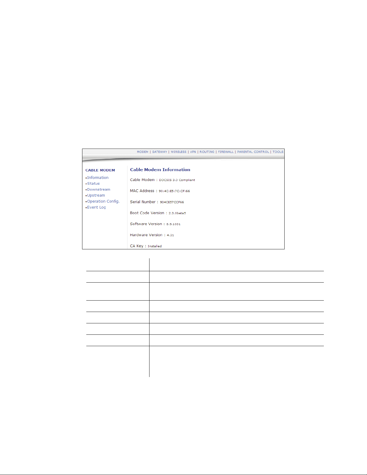
3.1 Cable Modem - Information
This section explains how to use the Information screen of the web interface. The
Information screen displays the device’s core software configuration.
1. Access the web interface. Refer to page 7, if needed.
2. Click the Information link from the left side of the screen. Field explanations are
listed below the following screen example.
Label Description
Cable Modem The current DOCSIS standard of the device.
MAC Address The unique Media Access Control (MAC) hardware address of cable
modem.
Serial Number The unique manufacturer serial number of the device.
Boot Code Version The boot software code version of the device.
Software Version The general software version of the device.
Hardware Version The internal version number that identifies the hardware design.
CA Key The device installs a Certificate Authority (CA) key that is transferred
from the service provider’s server after the cable modem is
authenticated. The key is used to secure communication between
the service provider and the cable modem.
12 DDW3612 Subscriber User Guide • July, 2010
Ubee Interactive 3.2 Cable Modem - Status
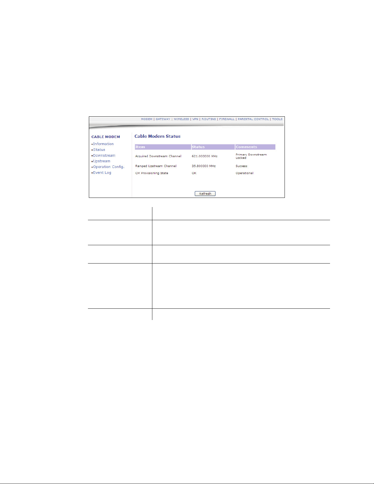
3.2 Cable Modem - Status
This section explains how to use the Status screen of the web interface. The Status
screen displays the device’s general connection information.
1. Access the web interface. Refer to page 7, if needed.
2. Click the Status link from the left side of the screen. Field explanations are listed
below the following screen example.
Label Description
Acquired
Downstream
Channel
Ranged Upstream
Channel
CM Provisioning
State
Refresh Click to refresh the status information.
Displays a Downstream channel that the cable modem is trying to
lock to and the progress.
Displays an Upstream channel that the device is trying to range with
and the progress.
After the physical initialization, the cable modem will be configured
by a DHCP server from the service provider. Once the cable modem
obtains an IP address, the cable modem’s status is OK. The Status
column also shows the connection progress. The Comments column
displays the messages indicating connection error information, if
errors occur.
DDW3612 Subscriber User Guide • July, 2010 13
3.3 Cable Modem - Downstream Ubee Interactive
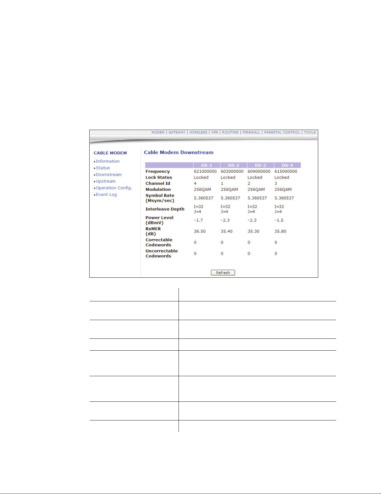
3.3 Cable Modem - Downstream
This section explains how to use the Downstream screen of the web interface. The
Downstream screen displays detailed information on the device’s connection to
downstream channels from the service provider.
1. Access the web interface. Refer to page 7, if needed.
2. Click the Downstream link from the left side of the screen. Field explanations are
listed below the following screen example.
Label Description
Frequency Displays the downstream channel frequency on which the
cable modem is scanning.
Lock Status Displays if the cable modem succeeded in locking to a
downstream channel.
Channel ID Displays the downstream channel ID.
Modulation Displays the modulation method that’s required for the
downstream channel to lock on to by the cable modem.
This method is determined by the service provider.
Symbol Rate Displays the symbol rate. The current cable modem
downstream symbol rates are: QAM64 is 5056941
sym/sec, QAM256 is 5360537 sym/sec.
Interleave Depth Displays the current cable modem downstream Interleave
depth (4/8/16/32/64/128/other).
Power Level Displays the receiver power level after ranging process.
14 DDW3612 Subscriber User Guide • July, 2010
Ubee Interactive 3.4 Cable Modem - Upstream
Label Description
RxMER The Receiver Modulation Error Ratio is used to quantify the
performance of a digital radio receiver in a communications
system using digital modulation.
Correctable Codewords Displays the quantity of codewords which are correctable.
Uncorrectable Codewords Displays the quantity of codewords which are not
correctable.
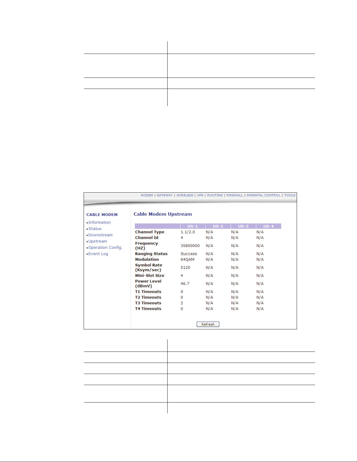
3.4 Cable Modem - Upstream
This section explains how to use the Upstream screen of the web interface. The
Upstream screen displays detailed information on the device’s connection to
upstream channels to the service provider.
1. Access the web interface. Refer to page 7, if needed.
2. Click the Upstream link from the left side of the screen. Field explanations are
listed below the following screen example.
Label Description
US-1 to US-4 Upstream Channels.
Channel Type Displays the channel type.
Channel ID Displays the current cable modem upstream channel ID.
Frequency Displays the current cable modem upstream frequency
(Hz).
Ranging Status Displays the upstream ranging status.
DDW3612 Subscriber User Guide • July, 2010 15
3.5 Cable Modem - Operation Config Ubee Interactive
Label Description
Modulation Displays the current cable modem upstream modulation
type (QPSK/ QAM8 /QAM16/ QAM32/ QAM64/ QAM128/
QAM256).
Symbol Rate Displays the symbol rate (Ksym/sec).
Upstream Mini-Slot Size Displays the current cable modem upstream mini-slot size
in Timebase Ticks of 6.25.
Power Level Displays the current cable modem upstream transmit
power (dBmV).
T-1 through T-4 Timeouts T-1-Displays DHCP time expiration, T-2-Displays DHCP
time expiration, T-3-Displays RNG-RSP time expiration, T4-Displays RNG time expiration.
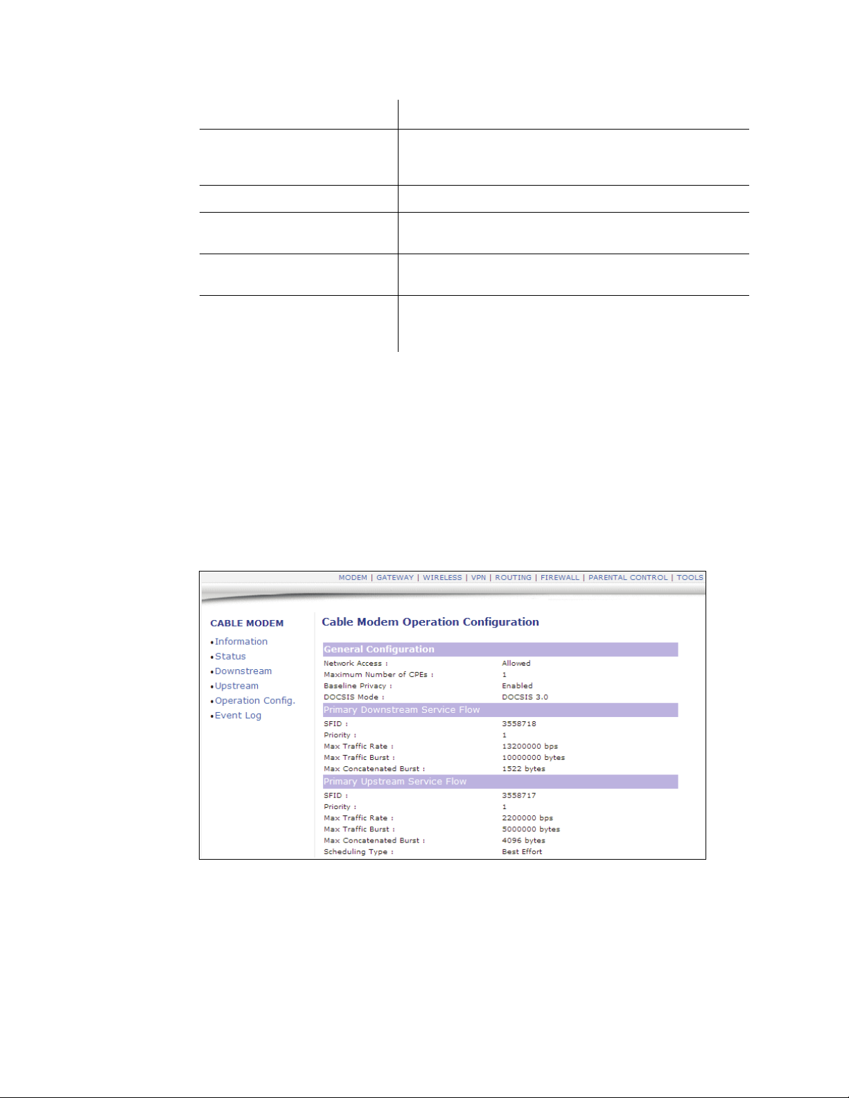
3.5 Cable Modem - Operation Config
This section explains how to use the Operation Config screen of the web interface.
The Operation Config screen displays general information on the device’s active
operational capabilities.
1. Access the web interface. Refer to page 7, if needed.
2. Click the Operation Config link from the left side of the screen. Field explanations
are listed below the following screen example.
16 DDW3612 Subscriber User Guide • July, 2010

Ubee Interactive 3.5 Cable Modem - Operation Config
Label Description
Network Access Displays the status of cable modem, Denied means no
connectivity is established. Allowed means connectivity is
established to Internet.
Maximum Number of CPEs Displays the maximum number of Ethernet devices that
can be connected (LAN side) to access the
network/internet at the same time.
Baseline Privacy Displays highlighted device configurations, like PHS
Enabled and the other examples shown in the screen
example.
DOCSIS Mode Displays the DOCSIS version used in the device.
Primary Downstream Service Flow
SFID Displays the frequency ID of the downstream service flow.
Priority Displays the use priority of the frequency ID.
Max Traffic Rate Displays the max data rate as enabled by the service
provider.
Max Traffic Burst Displays the max data rate as enabled by the service
provider for downstream data bursts.
Max Concatenated Burst Displays the max data rate per downstream burst.
Primary Upstream Service Flow
SFID Displays the frequency ID of the upstream service flow
Priority Displays the use priority of the frequency ID.
Max Traffic Rate Displays the max data rate as enabled by the service
provider.
Max Traffic Burst Displays the max data rate as enabled by the service
provider for upstream data bursts.
Min Traffic Rate Displays the minimum data rate as enabled by the service
provider.
Max Concatenated Burst Displays the max data rate per upstream burst.
Scheduling Type Displays the data scheduling type.
DDW3612 Subscriber User Guide • July, 2010 17
 Loading...