

Page 1
Ulyanovsk Automobile Plant, PJSC
Motor Vehicles
UAZ PATRIOT,
UAZ PICKUP,
UAZ CARGO
Operation Manual
OM 05808600.132-2011
Sixth Edition
2016
Page 2

2
© PJSC, Ulyanovsk Automobile Plant, 2016
WARNING!
The Operation Manual details the necessary rules of motor
vehicle operation and maintenance.
Prior to motor vehicle operation, please read the Operation
Manual and the vehicle log book carefully.
In particular, please read the sections "Safety requirements and
warnings", "New motor vehicle running-in" and "Engine start-up
and stop" carefully.
Improper operation can lead to injuries, malfunction in the motor
vehicle and its assemblies and termination of the manufacturing
plant's warranty liabilities.
For safety and fault-free motor vehicle operation please observe
the operation and maintenance instructions specified in the Manual.
Motor vehicle maintenance may be handled by one of the service
stations recommended by the company that sold the motor vehicle.
The service stations are provided with the necessary spare parts,
special tools sets and instruments. All motor vehicle maintenance
works are carried out by experienced specialists.
Due to continuous work on motor vehicle enhancement, the
design may be subject to modifications not described in the present
publication.
Have a great trip!
Page 3

3
Chapter 1. GENERAL INFORMATION
Motor vehicle UAZ Patriot (UAZ-3163, UAZ-31638) —
light, two-axle, off-road, 4x4 type, with an all-metal five-door
bodyshell.
Motor vehicle UAZ Pickup (UAZ-23632, UAZ-23638) —
cargo-carrying (pickup), two-axle, off-road, 4x4 type, with a
four-door cabin and a cargo compartment.
Motor vehicle UAZ Cargo (UAZ-23602, UAZ-23602-01,
UAZ-23602-02, UAZ-23608, UAZ-23608-01, UAZ-23608-02)
— cargo-carrying, two-axle, off-road, 4x4 type, with a two-door
cabin and a cargo bed, grocery and general purpose van.
The motor vehicles are designed for public conveyance and
freighting over all types of roads and terrain.
The motor vehicles manufactured in "U" as per Category 1 of
GOST 15150 are meant for operation under ambient operating
temperatures of -40 up to +40°C, air relative humidity of up to
100 % at +25°C, air dust content of up to 1.0 g/m3 and wind
speed of up to 20 m/s including in the regions located at altitudes
of up to 3,000 m above sea level with a corresponding reduction
of traction-dynamic characteristics and fuel efficiency.
The motor vehicles manufactured in "T" are meant for
operation under ambient operating temperatures of -10 up to
+50°C, air relative humidity of up to 100 % at 35°C under
conditions specified above for the "U"-design motor vehicles.
The plus ("+") by the side of the part name (assembly)
description means that this part (assembly) shall be installed
into the motor vehicle in accordance with the package.
Page 4
4
MOTOR VEHICLE MARKING
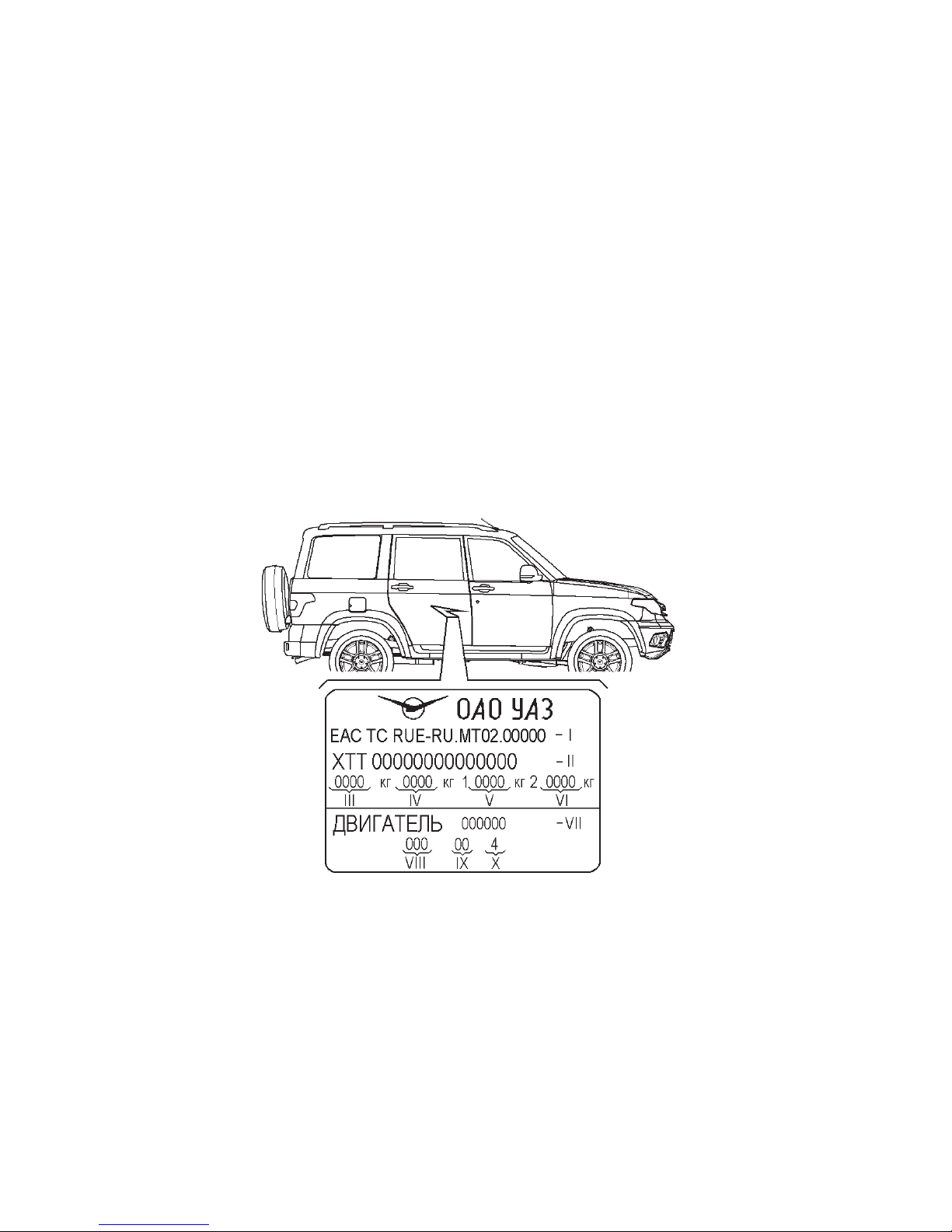
The motor vehicle's name plate (Fig. 1.1) is installed on the
B-pillar of the bodyshell side on the right-hand side of the motor
vehicle.
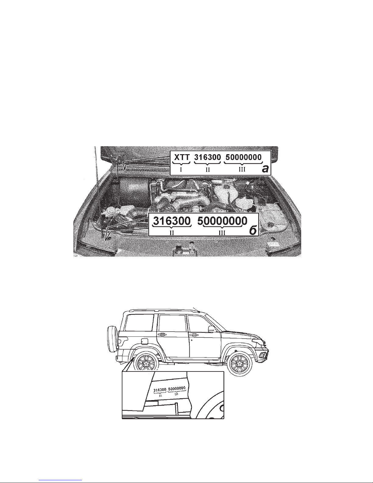
Vehicle identification number is marked on the name plate (Fig.
1.1) and on the motor vehicle body, on the bottom windsheild
panel (Fig. 1.2).
Identification number (Fig. 1.2) consists of three parts:
Part I — manufacturer international identification number,
means:
X — geographical zone, where manufacturing plant is located;
T — country code;
T — manufacturing plant code.
Descriptive part II — vehicle index.
Fig. 1.1. Motor vehicle name plate:
I — Full Transport Vehicle Type Approval number (TVTA);
II — Transport Vehicle identification number (VIN code);
III — Transport Vehicle maximum permissible weight;
IV — Maximum permissible weight of a transport vehicle with a trailer;
V — Maximum permissible load on the front axle;
VI — Maximum permissible load on the front back axle;
VII — Engine model identification;
VIII — Package code;
IX — Variant execution code;
X — Emission standard
Page 5
5
Fig. 1.2. Location of transport vehicle identification number and a bodyshell
number:
a — location of transport vehicle identification number;
b — location of bodyshell identification number
Fig. 1.3. Location of chassis identification number
Indicating part III — year of vehicle manufacture and its
order number.
Bodyshell identification number is stamped on the upper
radiator cowl frame connector (Fig. 1.2).
Chassis identification number is stamped on the right-hand
frame side member, at the rear (Fig. 1.3).
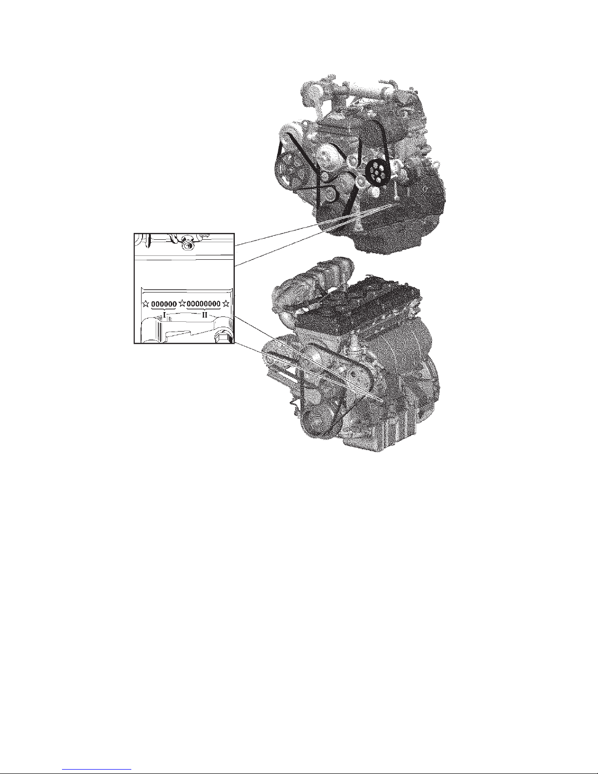
Engines ZMZ-40906 and ZMZ-51432's identification number
is stamped on the area located to the left of the crankcase, above
engine front support fastening lug bosses (Fig. 1.4).
Page 6
6
Fig. 1.4. Location of ZMZ-40906 and ZMZ-51432 engines' identification
number:
I — descriptive part (VDS) consists of six characters. The first five characters
(digits) represent the engine model code. If a model code contains fewer than five
characters, a zero shall be entered in the free space at the end of the identification. A zero shall be entered in place of the sixth character. II — indicating part
(VIS) consists of six characters. The first character (a letter or a digit) represents
the conditional code of the year of vehicle manufacture, the second character
(digit) is the conditional code of the engine manufacturing plant's division, and
the remaining characters (digits) are the order number of the engine since the
start of the year of engine manufacture.
ZMZ-40906
ZMZ-51432
Page 7

7
SPECIFICATION
UAZ Patr iot UAZ Pick up UAZ Cargo
Designation UAZ-3163 UAZ-31638 UA Z-23 632 UAZ-2 3638
UAZ-23602
(01/02)
UAZ-23608
(01/02)
1 2 3 4 5 6 7
General data
Vehicle dimensions* Shown in Fig. 1.5-1.11
Maximum bearing capacity
(including driver and
passengers), kg
600 800
800
(665/575)
Seating capacity
(including driver's seat)
5 5 2
Maximum gross vehicle weight,
kg
2,650 2,690 2,860 2,940 2,775 2,825
Gross weight distribution over
axles, kg:
on the front axle 1,217 1,26 0 1,230 1,285
1,09 0
(1,145/1,132)
1,130
(1,195/1,182)
on the back axle 1,433 1,430 1,630 1,655
1,685
(1,630/1,643)
1,695
(1,630/1,643)
Vehicle weight in r unning
order (including driver), kg
2,125 2,165 2,135 2,215
2,050
(2,185/2275)
2100
(2,235/2,325)
* Dimensions are averaged, given for reference and can vary depending on operation conditions, installed tires, their condition and
tire pressure, motor vehicle load, suspension condition, etc.
Page 8
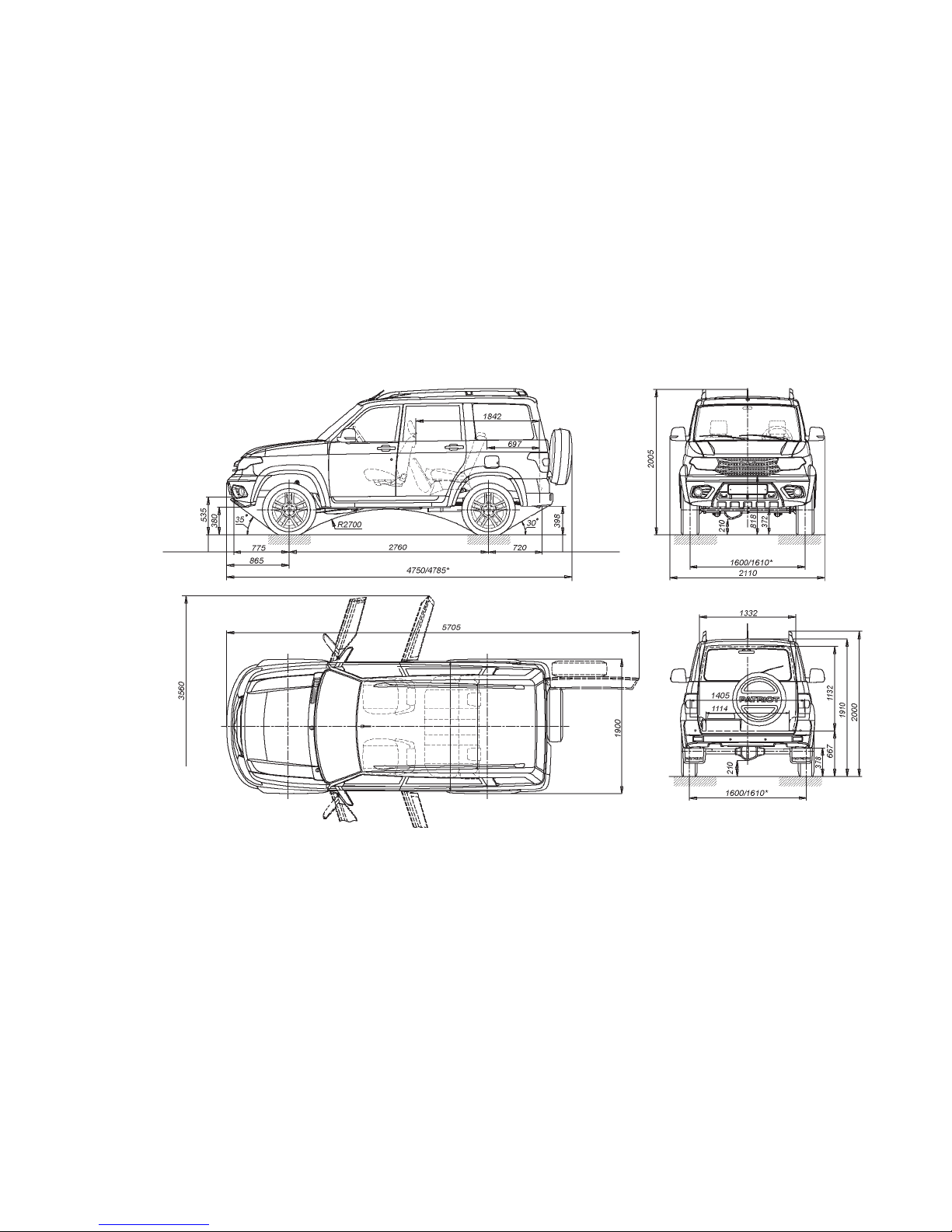
8
Fig. 1.5. Main dimensions of UAZ
PATRIOT motor vehicle with gross
weight (dimensions are given for
reference)
* — depending on package
To center
of tow eye
To center
of tow eye
Page 9
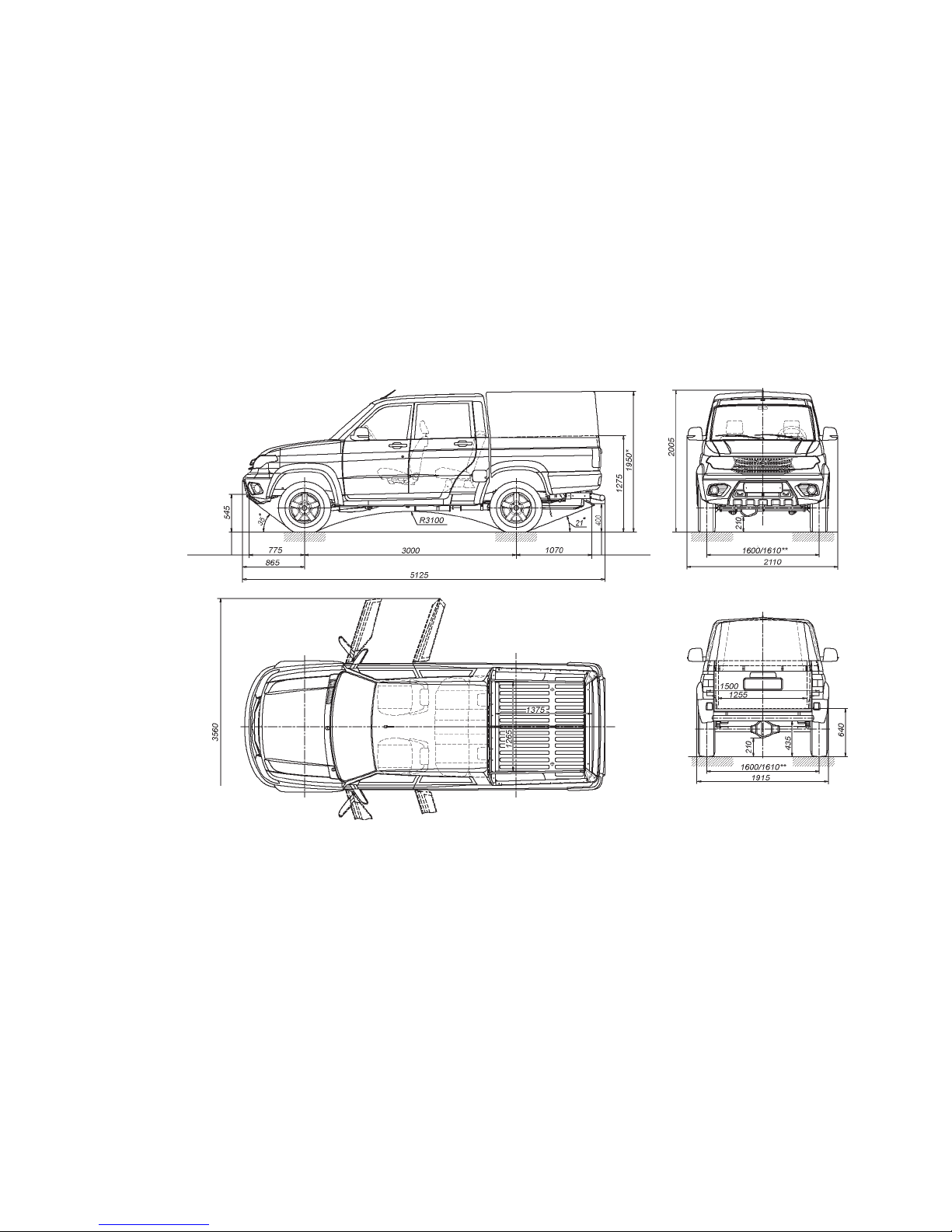
9
Fig. 1.6. Main dimensions of UAZ PICKUP
motor vehicle with gross weight
(dimensions are given for reference)
* — dimensions with tonneau cover
** — depending on package
To center
of tow eye
To center
of tow eye
Page 10
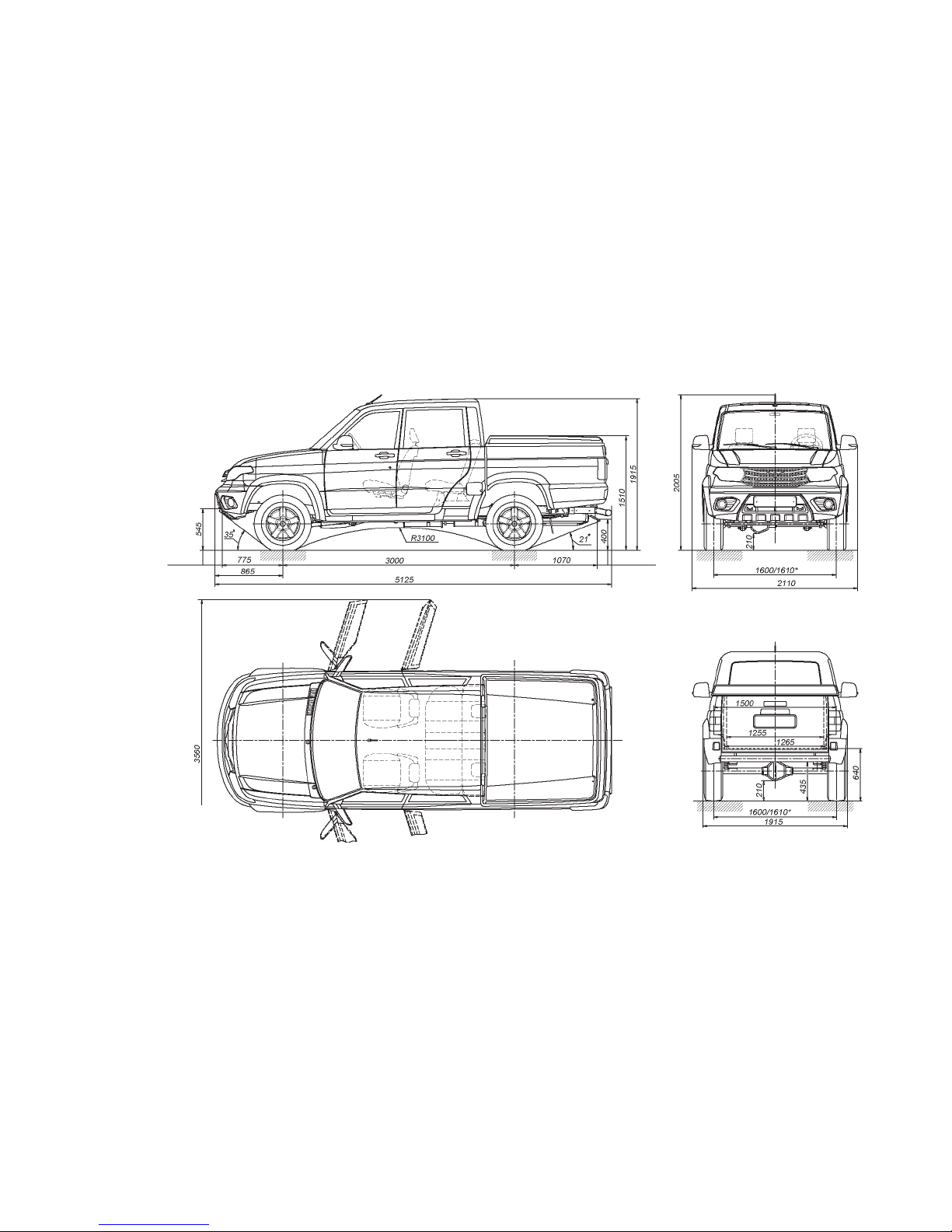
10
Fig. 1.7. Main dimensions of UAZ
PICKUP motor vehicle with a load box
cover with gross weight (dimensions are
given for reference)
* — depending on package
To center
of tow eye
To center
of tow eye
Page 11
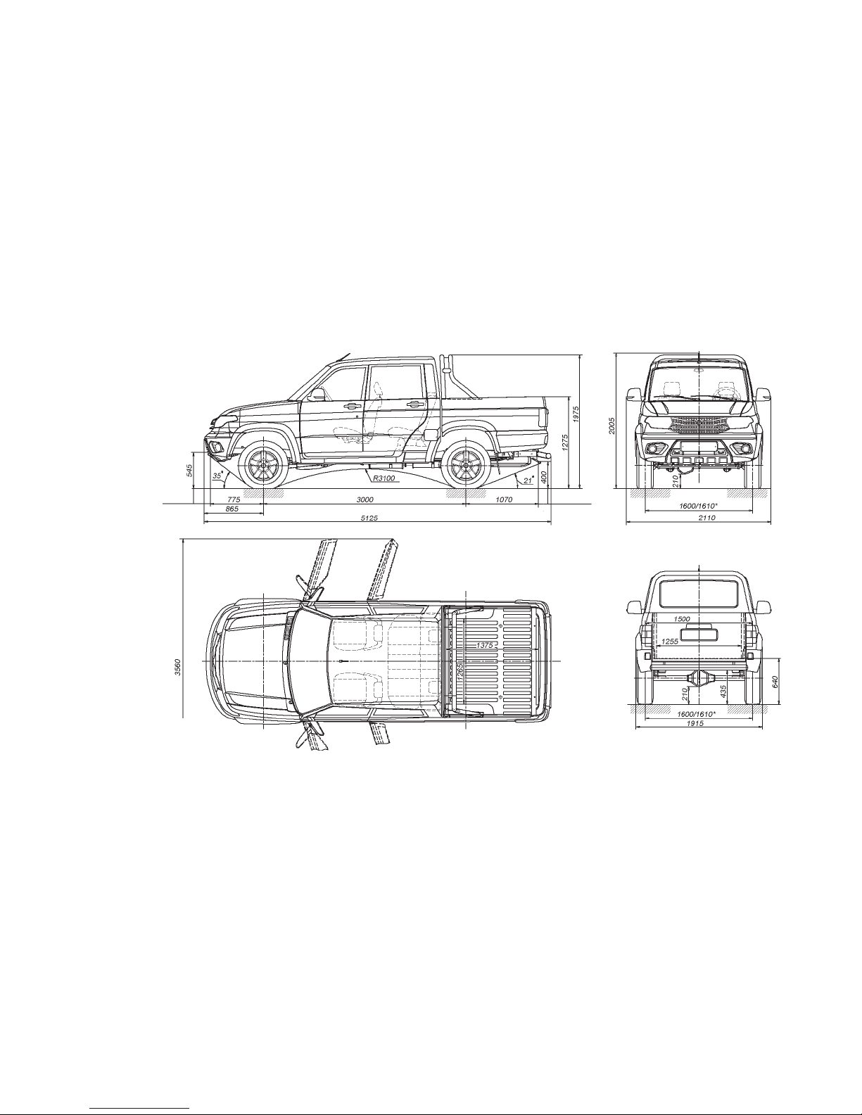
11
Fig. 1.8. Main dimensions of UAZ
PICKUP motor vehicle with a load
box top bow (dimensions are given
for reference)
* — depending on package
To center
of tow eye
To center
of tow eye
Page 12
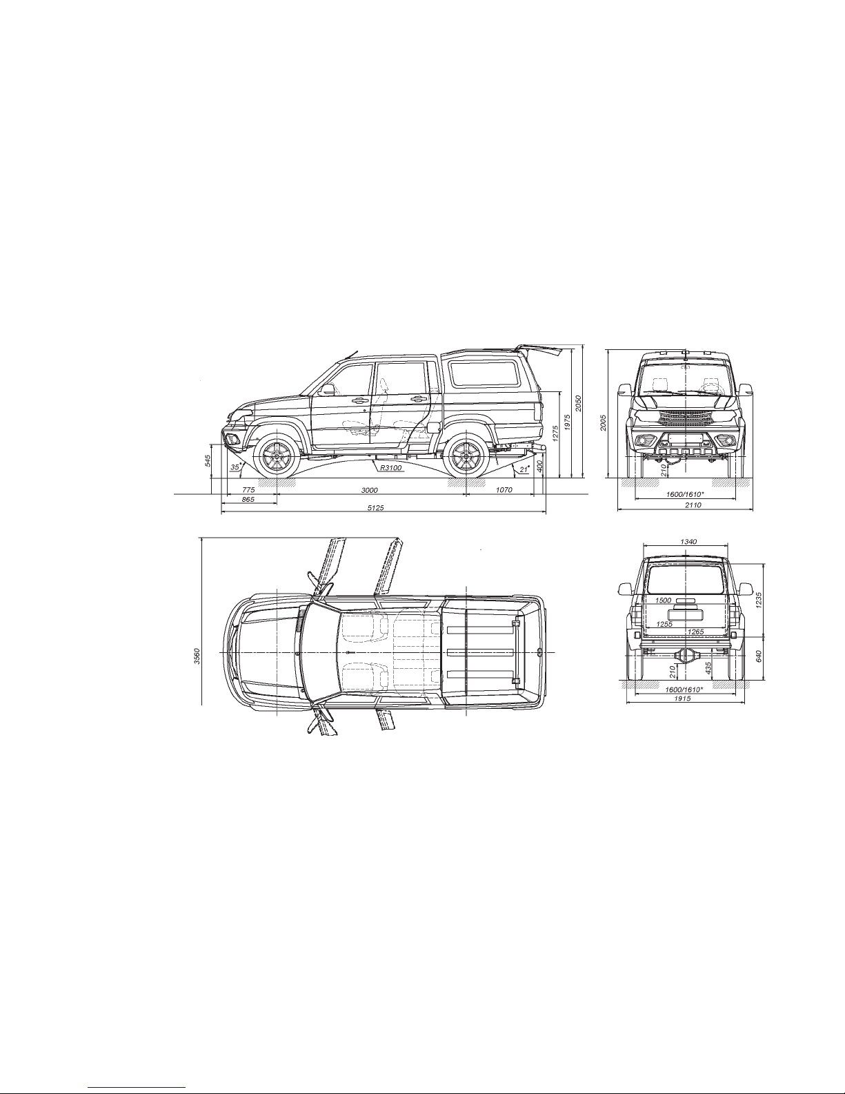
12
Fig. 1.9. Main dimensions of UAZ PICKUP
motor vehicle with a load box shelter
with gross weight (dimensions are given
for reference)
* — depending on package
To center
of tow eye
To center
of tow eye
Page 13
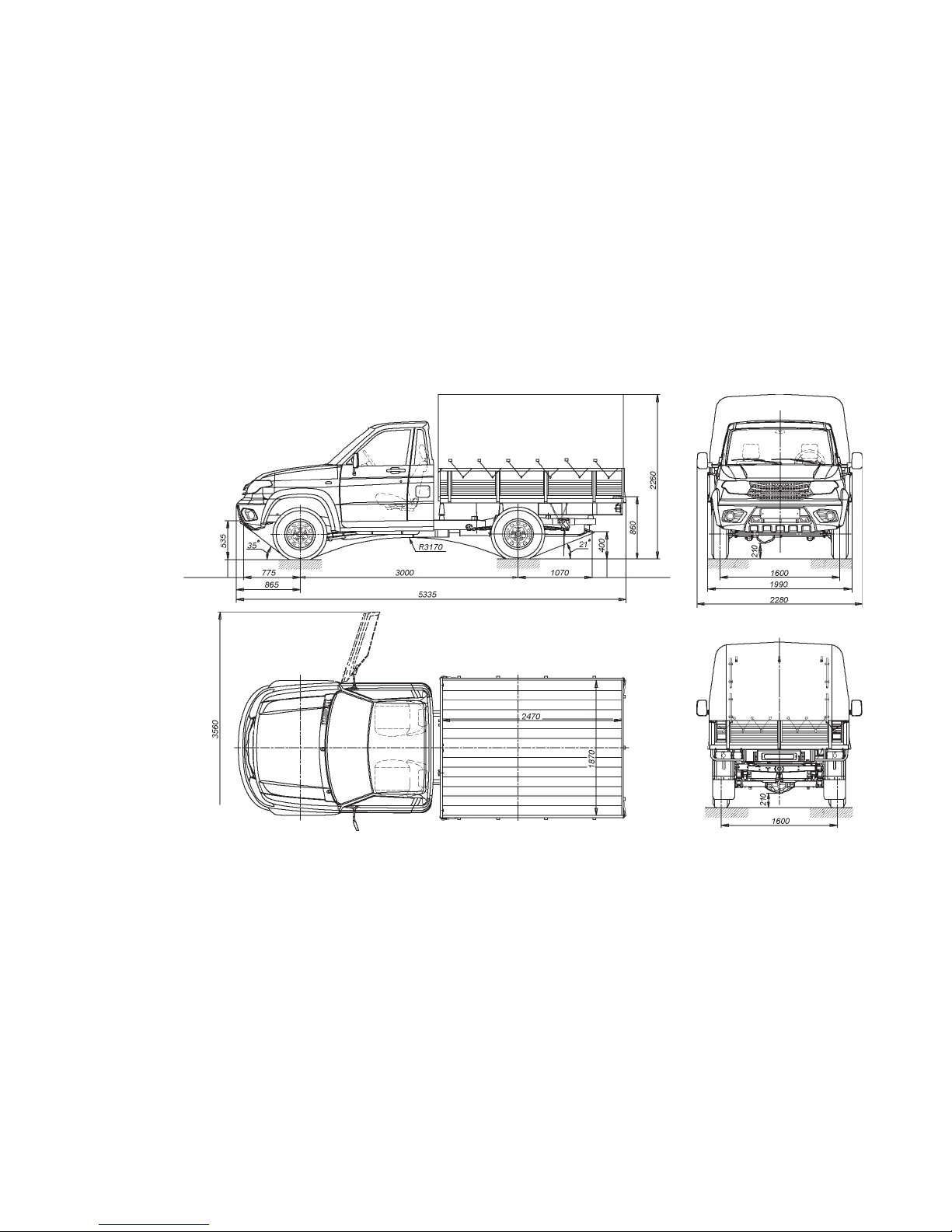
13
Fig. 1.10. Main dimensions of UAZ
CARGO motor vehicle with gross weight
(dimensions are given for reference)
To center
of tow eye
To center
of tow eye
Page 14
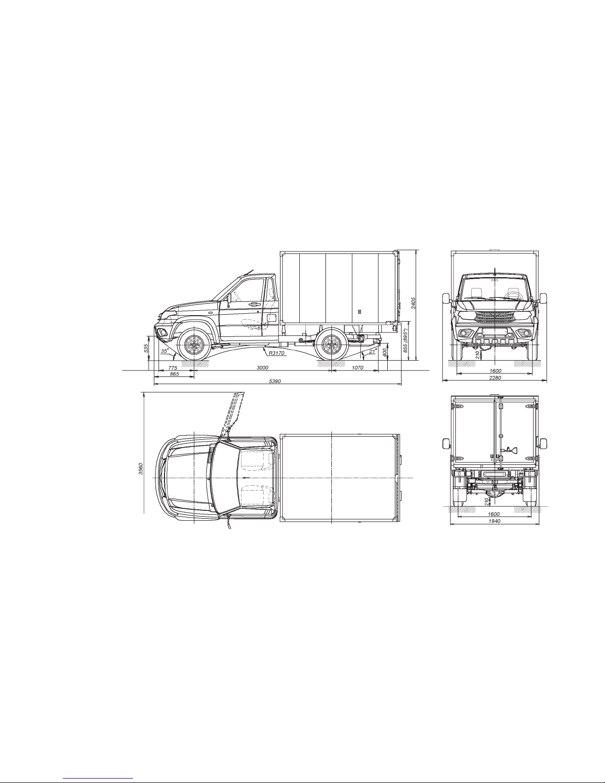
14
Fig. 1.11. Main dimensions of UAZ CARGO
motor vehicle with a food van or a general
purpose van with gross weight
(dimensions are given for reference)
* — dimension for an insulated van
To center
of tow eye
To center
of tow eye
Page 15

15
Unladen weight distribution
over axle, kg:
on the front axle 1,150 1,190 1,150 1,205
1,120
(1,096/1,097)
1,160
(1,147/1,149)
on the back axle 975 975 985 1,010
930
(1,0 89/1,178)
940
(1,088/1,176)
Maximum speed, km/h 150 135 140 135 135 (125*) 135 (125*)
Fuel consumption rate moving
at uniform velocity
90 km/h, l/100 km
11.5 9.5 12 10 12 (13. 5*) 10 (11.5*)
Fuel consumption rate moving
at uniform velocity
120 km/h, l/100 k m
15.5 12.5 15.6 12.6 – –
Note: Fuel consumption rate is used to determine the motor vehicle's technical condition and shall not be the operation
standard. Fuel consumption measuring accuracy is only provided when conducting special testing in strict adherence with the
requirements of GOST 20306-90 when the motor vehicle total haul has reached 9000-10000 km.
Gross weight of a towed trailer,
kg, max.:
equipped with brakes 1500**
without brakes 750**
* With tonneau cover and vans
** In case of a ball-type tow-hitch
1 2 3 4 5 6 7
Page 16

16
Minimum turning circle along
the axle, external (relative to
the turning center) wheel, m,
max.
6.55
7.0 8
Minimum turning circle,
external, by the front bumper
point, the most distant from
the turning center, m. max.
6.8 7.35
Maximum climb covered by a
motor vehicle of gross weight,
degree ( %)
31 (6 0)
Inmost wading depth, m 0.5
Engine
Model ZMZ-40906 ZMZ-51432
Designation UAZ-3163, UAZ-23632, UAZ-23602 UAZ-31638, UAZ-23638,UAZ-23608
1 2 3
Type four-stroke, with spark-plug ignition diesel turbo-charged
Cylinder number Four
Cylinder arrangement In-line, vertical
Firing order 1-3-4-2
Cylinder diameter, mm 95.5 87
Piston stroke, mm 94 94
1 2 3 4 5 6 7
Page 17

17
Actual displacement, cm
3
2,693 2,235
Compression ratio 9.1 19.0
Minimum rotation frequency
for crankshaft in idle, min.
-1
800-900 850-900
Maximum torque, N•m
(kgf•m) as per Rules 85
UNECE GOST R 41.85)
217.0 (22.1)
at 3,900 min.
-1
270 (27.5)
at 1,300-2,800 min.
-1
Maximum capacity, kW (h.p.):
as per Rules 85 UNECE
(GOST R 41.85)
99.0 (134.6)
at 4,600 min.
-1
83.5 (113.5)
at 3,500 min.
-1
Lubricating system Combined: force-feed and splash
Crankcase ventilation Closed
Fuel feed system Distributed fuel injection with electronic control
Fuel Lead-free petrol "Regular-92" (A I-92-4)
GOST R 51105,* AI-92-K4 GOST 32513,
it is permitted: Premium Euro-95" type II
(AI-95-4) and Super Euro-98 type II
(AI-98-4) GOST R 51866, AI-95-K4,
AI-98-K4 GOST 32513.*
Diesel fuel "EURO", type II and III
as per GOST R 52368-2005 (EN 590:2009),
grade or class depending on
of climatic conditions
Cooling system Liquid, closed with forced-circulation
* For motor vehicle packages of emission standard 5 apply similar fuel of class 5, type III and K5
1 2 3
Page 18

18
Transmission
Designation UAZ-3163 UAZ-31638 UAZ-23632 UAZ-23638 UAZ-23602 UAZ-23608
1 2 3 4 5 6 7
Clutch:
clutch type
drive type
Dry single-plate
Hydraulic
Gear box:
gear box type
control type
Mechanical, five-speed
Mechanical
Transfer case: With front axle drive decoupling
type of transfer case Two-stage by "Dymos" UAZ PJSC
control type With electric control. Mechanic power take-off.* Possible for the drive (at vehicle driving
and parking) of special packs, installed in the bodyshell, the power take-off box is installed
The front and back universaljoint shafts
Open type, with two universal joints and a movable spline connection. The back universaljoint drive can have an intermediate bearing with a hinged joint
Front and back drive axles:
axle type
steering pivots of the front
axle
Single-reduction
Ball equal angular speeds
Running gear
Suspension:
suspension type
Dependent , front suspension — springing, on two longitudinal and one lateral arm, with an
anti-roll bar, rear suspension — on two longitudinal semi-elliptic leaf-less springs with an
anti-roll bar
* For motor vehicles with a transfer case by UAZ PJSC
Page 19

19
Shock absorbers Four, hydro-pneumatic, telescopic, bilateral
Wheels and tires:
wheels Disc, with a whole rim, steel 6 1/2 Jx16H2 with a radial, tubeless tire 225/75R16 or of light-
metal alloy 7Jx16H2, 7Jx18H2 with radial tubeless tires 235/70R16, 245/70R16, 245/60R18
with hubcaps. Wheel mounting — by five nuts. A spare wheel with tires 16"- with a steel
wheel, with a tire 245/60R18 — with a light-alloy wheel.
Control systems
Steering system
steering mechanism type
Steering post with height adjustment of a steering wheel
"Screw-ball nut-rack-quadrant" with electrically powered hydraulic steering
Brakes
pedal brake type
type of drive pedal brake
parking brake type
parking brake actuator type
With front disc brakes and back drum brakes.
Hydraulic, dual-circuit, diagonal-split, with A BS or with circuit splitting by axes with a
pressure regulator valve without A BS, with a vacuum booster.
According to the package, motor vehicles can be equipped with an anti-locking braking
system (in this case there is no mechanical pressure controller). Circuit splitting is diagonal
(primary — right hand front and left hand back wheel, secondary — left hand front and right
hand back wheel).
Wheeled, combined with rear brakes or drum and transmission
Mechanical
1 2 3 4 5 6 7
Page 20

20
Electric equipment
Designation UAZ-3163, UAZ-23632, UAZ-23602 UAZ-31638, UAZ-23638, UAZ-23608
1 2 3
Wiring system Single wire, the negative pole is connected with motor vehicle earth
Line voltage (rated), V 12
Generator 11.203.640 by Pramo-Iskra) 14V, 80A,
5122.3771 (Pramo-Electro) 14V, 80A
for motor vehicles with A/C —
5122.3771-30 (Pramo-Electro) 14V, 120A,
32112.3771, Borisov, BATE 14V, 110A
AAK 5730 ("Iskra") 14V, 80A ,
5122.3771 (Pramo-Electro), 14V, 80A or
3212.3771, Borisov, BATE 14V, 90A
for motor vehicles with A/C —
AAK 5727 ("Iskra") 14V, 120A or
5122.3771-30 (Pramo-Electro) 14V, 120A
Accumulator battery 6ST-66A3 (6ST75A)* 6ST90A
Spark plugs AU14DVRM GOST P53842,
DR17YC-F f. BRISK
–
Heating plugs – 0250 202 029 ("BOSCH")
Starter 11.131.568 12V 1.9 kW (Pramo-Iskra)
5112.3708 12V, 1.2 kW (BATE)
AZE 2203 (Pramo-Iskra) 12V — 1.9 kW,
AZE 2154 ("Iskra") 12V — 1.9 kW
6012 (ZIT OJSC), Samara, 12V — 1.7 kW
Engine control unit BOSCH 0261 S07 321 BOSCH 0 281 018 675
Ignition starter switch With an anti-theft device and a starter re-engagement lock
Audio electric signal One signal — membrane Two signals — tone, horn
* For winter package
Page 21

21
Windshield wiper Electrically driven, with two brushes, three-mode, with pause adjustment in intermittent
operation mode
*Tail gate window wiper Electrically driven, with one brush
Washer Electrically driven, for windshield and rear window+
Power windows Remote controlled
Electrical interlocking system Designed for simultaneous interlocking of all motor vehicle's door locks
*Safe parking system+ Designed to warn a driver of obstructions, located out of driver's sight, when motor vehicle
moving in reverse with max. speed of 5 km/h
Adjusting values
Designation UAZ-3163 UAZ-31638 UAZ-23632 UAZ-23638 UAZ-23602 UAZ-23608
1 2 3 4 5 6 7
Deflection of fan belt and
power steering pump at force of
4 kgf, mm
5-8 6-8 5-8 6-8 5-8 6-8
Deflection of generator belt
and cooling system pump at
force of 8 kgf, mm
14-15 – 14-15 – 14-15 –
Belt deflection of a fan drive,
a steering booster pump, A/C
compressor (option) at force of
4 kgf, mm
– 6-8 – 6-8 – 6-8
*For UAZ Patriot motor vehicles
1 2 3
Page 22

22
A gap between spark plug
electrodes, mm
0.7
+0.15
– 0.7
+0.15
– 0.7
+0.15
–
Brake pedal free play, mm 5-8
Front wheels toe-in 0°4'-0°10'
Largest turning angle front
inner wheel, deg.
31-32
Steering control total backlash
(steering wheel angle from the
position corresponding to the
beginning of steerable wheels
turning in one direction to
the steering wheel position
corresponding to the beginning
of steerable wheels turning in
the opposite direction), deg.,
max.
20
Wheel and tire in assembly
unbalance, g•cm, max.
1000
Tire pressure, MPa (kgf/cm
2
):
front wheels:
225/75R16
235/70R16
245/70R16
245/60R18
0.20 (2.0)
0.19 (1.9)
0.17 (1.7)
0.18 (1.8)
0.21 (2.1)
0.20 (2.0)
0.18 (1.8)
0.18 (1.8)
0.20 (2.0)
0.19 (1.9)
0.17 (1.7)
–
0.21 (2.1)
0.20 (2.0)
0.18 (1.8)
–
0.19 (1.9)
–
–
–
0.19 (1.9)
–
–
–
1 2 3 4 5 6 7
Page 23

23
Tire pressure, MPa (kgf/cm2):
back wheels:
225/75R16
235/70R16
245/70R16
245/60R18
0.24 (2.4)
0.22 (2.2)
0.21 (2.1)
0.20 (2.0)
0.24 (2.4)
0.22 (2.2)
0.21 (2.1)
0.20 (2.0)
0.27 (2.7)
0.25 (2.5)
0.24 (2.4)
–
0.27 (2.7)
0.25 (2.5)
0.25 (2.5)
–
0.28 (2.8)
–
–
–
0.28 (2.8)
–
–
–
Fuelling data (litres)
Fuel tanks: right/left 36/36
Engine cooling system 14.0
Engine lubrication system 6.5
Brake hydraulic drive system 0.6
Gearbox housing 2,5
Transfer housing:
"Dymos"
UAZ PJSC
1.8
0.8
Bevel gear housing:
front axle
back axle
1.5
1.4
Power hydraulic steering
system
1.25
Clutch hydraulic drive system 0.18
Windshield washer reservoir 5
1 2 3 4 5 6 7
Page 24

24
Chapter 2. SAFETY REQUIREMENTS AND WARNINGS
SAFETY REQUIREMENTS
1. When operating a motor vehicle it is necessary to observe
road traffic regulations and safety requirements, keep the motor
vehicle in good repair and carrying out timely maintenance and
correct possible malfunctions in order to avoid injury to yourself
and others.
2. The driver is responsible for the passengers. Therefore the
driver must ensure that his or her passengers observe safety rules.
Be specially careful when children are in the motor vehicle. Do not
leave children unattended in the motor vehicle.
3. It is prohibited to switch off IGN and remove the key from
the ignition starter switch when driving a motor vehicle.
4. When leaving the motor vehicle, do not leave door keys and
ignition keys inside.
5. Before opening the door, ensure that it will not be a hindrance
for other road users.
Before closing the door, make sure it will not catch someone or
something.
It is prohibited to drive a motor vehicle with any door opened.
6. Do not adjust tilt angle of steering column when driving a
motor vehicle.
7. Do not adjust the driver seat when driving a motor vehicle.
8. Observe the requirements of safe power window use. Do not
allow children to use power windows.
9. It is prohibited to use lamps that are not required by design.
10. Seat belts are an efficient means of driver and passenger
protection against drastic consequences of traffic accidents.
Use of seat belts is mandatory!
11. Worn, damaged, underinflated or overpressured tires, warped
wheels or wheel unfastening can cause a car crash.
12. Note that while the engine is off, the force required for
steering input and motor vehicle braking increases significantly.
13. If steering system or brake system does not work properly,
further motor vehicle driving or towing with a tow-rope is not
allowed. In this case you should use two wheel vehicle towing or a
tow truck service.
14. After long parking (over 1 hour) in a motor vehicle with
a diesel engine, only begin driving at least 20 to 30 seconds after
Page 25

25
starting the engine so that the vacuum pump creates a depression
in the vacuum brake booster sufficient for comfortable braking.
15. It is prohibited to drive with engine switched off as brake
efficiency is lost.
16. It is strictly prohibited to disassemble shock absorbers.
17. It is prohibited to start and warm-up the engine in a confined
space that does not have proper ventilation.
18. Do not subject motor vehicle's packs to open flame.
19. Keep the engine clean (engine fouling can cause fire).
20. Make sure that the fuel tank's plugs are closed tightly and
there are no leaks from fuel lines.
21. Catalyst operational temperature is 400-800°C (UAZ-3163,
UAZ-23632, UAZ-23602) and 400-600°C (UAZ-31638, UAZ23638, UAZ-23608). It is prohibited to operate a motor vehicle
without catalyst protection screens. When driving a motor vehicle
and while parked, make sure that the exhaust system is not in
contact with flammable materials (e.g. dried grass).
22. When handling low-freezing liquid or fuel or brake fluid
please observe the following rules:
- avoid any operations as a result of which these liquids or
fumes can enter a mouth cavity;
- do not let liquid dry out on the skin, immediately wash it off
with soap and warm water;
- flush spilled liquid with water, ventilate the room;
- remove clothes contaminated with liquid, dry them outside the
room and wash;
- moisten petrol deposit with kerosene when scraping in order
to prevent poisonous particles from entering the respiratory system;
- when handling fuel, observe fire safety rules.
23. When a motor vehicle stops, it should be braked with the
parking brake.
24. When handling electrolytic solution, take special precaution.
In order to prevent poisoning and chemical burns please observe
the following rules:
- strictly observe the safety requirements specified in the
accumulator battery manual;
- keep electrolytic solution or fumes from entering the mouth
cavity, respiratory system or eyes as it is very dangerous;
- avoid any operation as a result of which the electrolytic solution
can get onto the skin. If the solution comes in contact with the
Page 26

26
skin, carefully wipe off electrolytic solution with cotton wool and
immediately rinse remaining traces on the skin with a 5 % solution
of ammonia and sodium carbonate;
- spilled electrolytic solution must be collected with a special
rubber bulb or a densimeter and flushed with water, and the room
must be ventilated;
- to charge the battery, it must be removed from the motor
vehicle and filler plugs must be unscrewed;
- the battery must be charged in a well-ventilated room. Electrolyte
fume accumulation is dangerous to health and explosive.
25. Do not wash a motor vehicle with a running engine. When
washing a motor vehicle, avoid spraying water directly onto electric
equipment articles, electronic devices, sensors and detachable
connections in the engine compartment. Monitor the condition of the
protective cases of electronic modules and sensors and detachable
connections. In case of moisture penetration, detachable connections
must be blown off with compressed air and processed with water
repellent vehicular preparation to protect terminals against oxidation.
26. A jacking apparatus installed improperly can cause serious
injury or motor vehicle damage. It is strictly prohibited to carry out
works under a motor vehicle supported only by a jacking apparatus.
27. It is prohibited to drive downhill with a gear thrown out in
the gear box or the transfer case or with the clutch thrown out.
28. For UAZ Pickup motor vehicles, the weight of cargo hauling
in a load box shall not exceed 425 kg.
29. For UAZ Pickup and UAZ Cargo motor vehicles, it is
recommended to trim the cargo or to place the cargo closer to the
cab.
30. Maximum permitted weight of the cargo hauling in the
trunk compartment (including trunk compartment weight), when
installing it on the UAZ Patriot motor vehicle's bows, shall not exceed
50 kg. In case of a motor vehicle without bows, cargo hauling on
the roofing is not provided.
31. When carrying out maintenance and operating repair of a
motor vehicle, the following requirements shall be met:
- before starting work, check tools and accessories for normal
operation, arrange work clothes: do cuff up, tuck clothes in so that
there are no hanging ends, tuck hair under closed-body hair cover;
- when carrying out any works, a motor vehicle must be securely
braked;
Page 27

27
- do not carry out maintenance operation and repair of a motor
vehicle with engine on, except for specific works that require engine
start according to the procedure, with that take special care;
- avoid bringing hands, parts of clothing and tools dangerously
close to operating drive belts, pulleys, etc.;
- the fuel supply system is under pressure with the engine
running after the fuel pump, therefore it is prohibited to carry out
maintenance (e.g. tightening joints) repair of subsystems with engine
on or immediately after its shutdown;
- take due care when opening the radiator cap of the engine
cooling system to avoid scalding;
- before arc welding operations, execution tanks shall be removed
and battery "-" terminal shall be disconnected;
- observe fire safety rules.
32. Waste oils and specialty liquids shall be collected and sent
for recycling or disposal.
33. Several safety requirements are detailed in the respective
chapters of the Manual.
WARNINGS
1. During the initial operating period all recommendations
specified in chapter "New motor vehicle running-in" shall be strictly
observed.
2. Switching engine malfunction lamp on does not mean that
the engine must be shutdown immediately. However, in case of a
malfunction caused by ignition failures (engine wobble and jerking
when driving a motor vehicle), a motor vehicle shall be immediately
(max. in 0.5 min.) stopped, and the engine shall be shut off in order
to prevent exhaust gas catalyst breakdown.
3. Do not start motor vehicle driving with a cold engine. Avoid
high crankshaft speed after starting a cold engine.
In order to prevent any difficulties when starting engine, follow
the instructions in chapter "Engine start".
4. In case of abnormal noises and knocks in a running engine,
find out the cause of their occurrence, a motor vehicle must not be
operated until the malfunction is corrected.
4.1. After starting a cold engine the hydraulic valve may knock,
that should disappear in the course of engine warm-up to the
coolant temperature of 80-90°C, but not more than in 30 minutes
after reaching the specified temperature. If knock persists, it is
Page 28

28
necessary to check oil feed to the hydraulic pushers or to replace
faulty hydraulic pushers.
5. For fail-safe operation and to prevent accelerator pedal
breakdown it is recommended:
- do not apply excessive loads on the pedal lever after operating
stroke ending;
- avoid impact, lateral and other loads that do not correspond
to the pedal operating stroke.
6. Engage back run in the gear box and underdrive in the
transfer case only when a motor vehicle completely stops.
7. Before fuelling motor vehicle, the heater-temperature booster
(if available) shall be switched off.
8. When driving over dry hard roads the front axle shall be
disengaged.
Avoid front axle engagement when driving a motor vehicle with
small turning radii.
9. In case of malfunction of any brake circuit brake pedal stroke
increases and brake efficiency decreases.
10. It is not recommended to operate diesel engine for more
than 10 minutes with minimum idle speed in order to prevent oil
penetration to the intake system from the turbocharge bearing
assembly.
11. In case of frequent brake pedal depressing in a diesel engine
motor vehicle (after releasing the pedal it is depressed again, e.g.
on downhill) the vacuum pump is not able to create the required
depression, wherefore braking capacity decreases and it will be
necessary to apply increased force to the brake pedal.
To ensure efficient braking, keep engine idle speed from going
below 850 min-1.
12. Be careful when carrying out any operation with the motor
vehicle hood opened, as the electric fan can switch on (irrespective
of whether engine is on or off) on command of the Engine Control
Unit.
13. Safe parking system is optional equipment that facilitates
motor vehicle driving but does not drive a motor vehicle itself,
therefore the manufacturing plant is not responsible for any possible
damages when driving in reverse.
14. It is prohibited to remove metal segments with engine on
and to check sparking charge "to ground".
Page 29

29
15. Avoid spilling acids, soda solutions, brake fluid, antifreeze
and fuel on the painted surface of the bodyshell, wheels and rubber
parts.
16. In order to prevent turbidity of the headlamp assembly lenses
and scratches on them:
- dry foreign materials on the external surface of the lens must
be cleaned off only by pre-moistening them with plenty of water;
- do not apply aggressive chemical substances (petrol, acetone,
solvents, etc.), aggressive detergents and sharp objects to clean
headlamp assembly lens;
- to prevent overheating of the headlamp assembly lens, do not
switch on heavily polluted headlamp assemblies. Do not switch on
headlamp assemblies covered with any object.
17. Before washing motor vehicle in an automatic washer and
entering low-ceilinged rooms, always remove the antenna otherwise
it can be damaged. To remove the antenna, unscrew it counterclockwise. To install, screw it in clockwise.
18. When folding the two-passenger section of the back triple
seat make sure that the middle seat belt is not fastened. Monitor
the condition of the plastic limiting clip of the middle seat belt.
19. Using the heater fan at above average to maximum operation
modes under pouring rain conditions can result in soaking of the
filter for air entering the interior and dripping ingression of moisture
at the feet of the front passenger.
20. Avoid impact loads on the motor vehicle chassis. In case of
strong blows to the front wheels, carefully inspect the wheels, all
parts of the front axle, steering links, steering gear and engine oil
pan and correct detected defects.
21. To prevent excessive loads on the axle differential, avoid
long-term slipping of one of the wheels.
22. When operating a motor vehicle in cold season (ambient
temperature is max. 0°C) it is recommended to apply a cold weather
radiator cowl cover.
To prevent freezing through of the engine positive crankcase
ventilation control system junction pipe, at ambient temperature
below (-15°C) it is necessary to disconnect the resonator-type hose
from the air filter, turn the filter tightly counter-clockwise (the air
filter inlet spigot will be backward and downward directed).
At ambient temperature below -30°C it is recommended to operate
the motor vehicle with the front axle continuously engaged.
Page 30

30
23. If duration of motor vehicle parking exceeds 12 hours at
ambient temperature below -30°C, it is recommended to store the
accumulator battery in a warm room.
24. To prevent oil overheating and power steering pump
malfunction it is not recommended to hold the steering wheel in
an extreme position for more than 5 sec.
25. Use only recommended lubricants and specialty liquids.
26. Knocks in the transfer case are possible at the moment of
front axle engagement.
27. When switching on the A/C and with the transmission control
lever in the neutral position, pings in the gear box synchronizer rings
are possible. These pings can increase with high gear actuation and
with the front wheels turned to the limit.
28. The opened lift gate or the back header can block visibility of
the back lighting means of your motor vehicle for other road users.
Before opening the lift gate of UAZ Patriot or the back header of
UAZ Cargo motor vehicle, install breakdown triangle on the road
as per GOST R 41.27-99.
Tightening torques of main threaded joints are shown in Annex
2 of the Manual.
30. Long-term, fault-free and safe operation of a motor vehicle
depends on accurate compliance with the requirements of the Manual
and the vehicle log book.
31. The plant continuously improves the design of its motor
vehicles, hence the latest engineering changes that do not affect
operation may not be reflected in this Manual edition.
Page 31

31
Chapter 3. CONTROL ELEMENTS, MOTOR VEHICLE
INTERIOR AND BODYSHELL EQUIPMENT
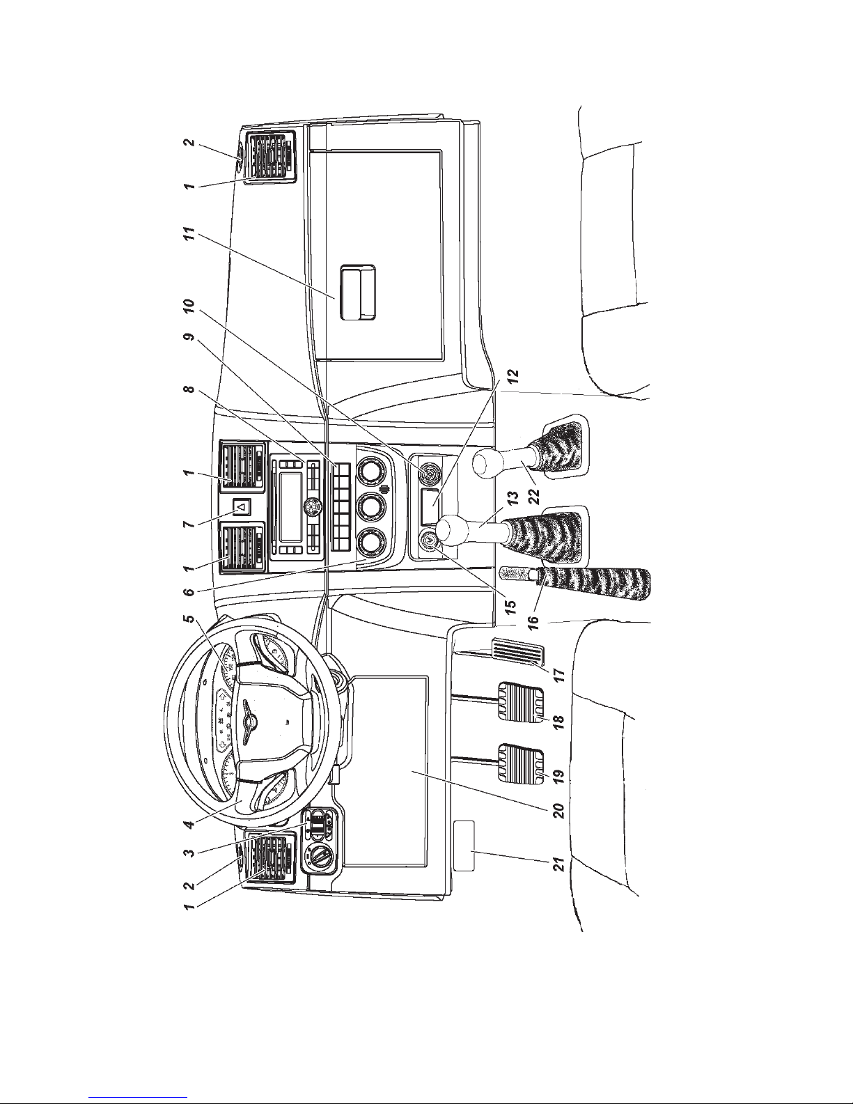
Layout of the control elements and the driver seat equipment
is shown in Figs. 3.1, 3.2 :
1 — cowling (see section "Interior heating and ventilation").
2 — side window blower nozzle.
3 — lighting mean control module (Fig. 3.4).
4 — steering column with a steering wheel, an ignition starter
switch, multi-function switches and a steering column tilt angle
control lever (Fig. 3.5).
5 — instrument cluster (Fig. 3.6).
6 — control panel of heating and ventilation and climate control
systems (see section "Interior heating and ventilation").
7 — hazard switch.
8+ — multimedia system head unit.
9 — device switches. Set of switches depends on the motor
vehicle package:
— climate control system automatic operation switch;
— rear screen de-mist and mirror heating switch;
— mirror heating switch (for motor vehicles without rear
screen de-mist);
— recirculation switch;
- intensive windscreen heating switch;
— tank fuel sender switch.
— A/C switch;
— windscreen electrical heating switch. Briefly pressing
the switch key with ignition ON sends a signal to the heating
time relay, which actuates the heating element of the windscreen.
Windscreen electrical heating will be switched off in 12±2 min.
automatically or when the switch key is pressed again or when
key is off.
— preheater starting switch.
10 — 12V socket.
11 — glove compartment cover. To open the cover pull
the handle from below. The glove compartment is equipped
Page 32
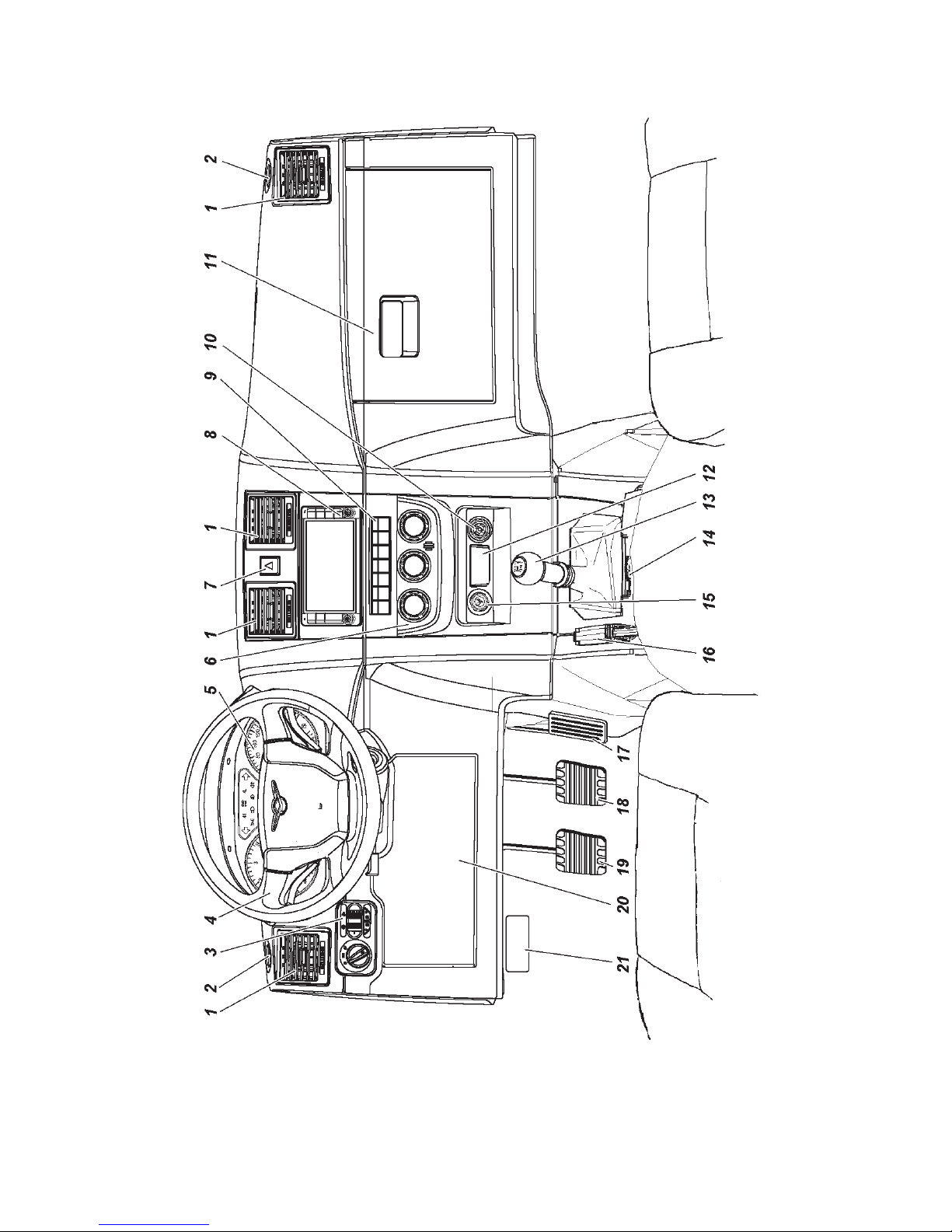
32
Fig. 3.1. Control elements and driver's seat equipment
for motor vehicles with the transfer case f. "Dymos"
(see item description in the text)
Page 33
33
Fig. 3.2. Control elements and driver's seat equipment
for motor vehicles with the transfer case of UAZ, PJSC
(see item description in the text)
Page 34
34
with a puddle lamp (depending on package) that switches on
automatically when the cover is opened.
12+ — starting preheater timer. (Operation and maintenance
information is specified in the manufacturing plant instruction
(manual) attached to the motor vehicle).
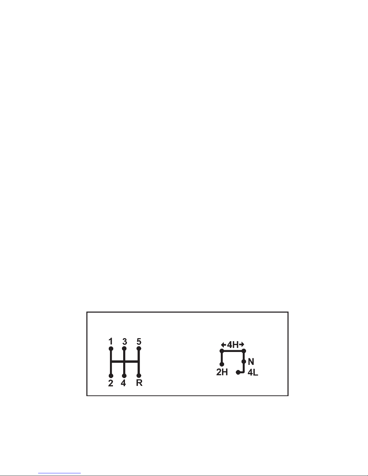
13 — shift lever. (See lever positions on the shift lever handle
and Fig. 3.3).
14 — floor standing box with units and keys (Fig. 3.7).
15 — cigar lighter. To heat up the cigar lighter coil, press
the insert handle until it is fixed and then release the handle.
When the required coil heating temperature is reached the insert
automatically resets.
It is not recommended to use the cigar lighter for electric
device connection.
16 — parking brake lever. To engage the parking brake,
position the lever up, to disengage press the button on the lever
face and position the lever down against stop.
17 — accelerator pedal.
18 — brake pedal.
19 — clutch engagement pedal.
20 — relay and fuses unit cover. For access to the unit, push
up the top cover part, surpassing spring lock forces, and pull it
out of the hooks in the lower part.
21 — bonnet latch opening lever.
22 — front axle and low gearing engagement lever (See lever
positions in Fig. 3.3).
Fig. 3.3. Positions of the gearbox and transfer case levers:
1-5 — gears; R — reverse gear; 2H — direct gear, the front axle is disengaged;
4H — direct gear, the front axle is engaged (the main position — left); N -neutral
position; 4L -the front axle and underdrive are engaged
Gear box Transfer case
Page 35
35
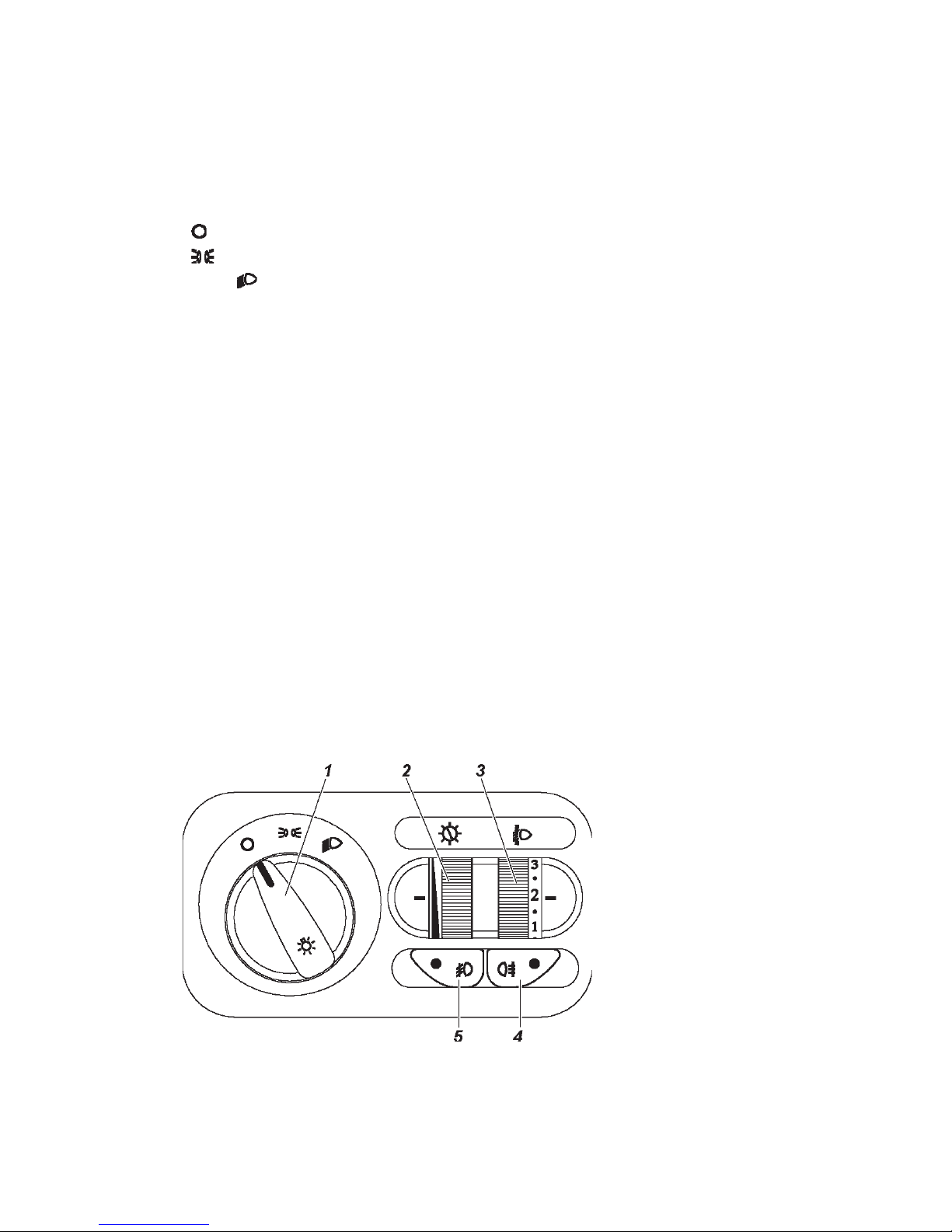
LIGHTING MEANS CONTROL MODULE
Lighting means control module (LMCM) is shown in
Fig. 3.4.
1 — external lights switch. Has three positions (clockwise):
" " — lighting is OFF (daytime running lights are ON if available);
" " — tail lamps, license plate light and cluster illuminating are
ON; " " — tail lamps, license plate light and cluster illuminating
, headlamps are ON.
2 — cluster dimmer. Light intensity is changed by turning
the regulator.
3 — headlamp corrector regulator. By turning the regulator, the
headlamp light beam inclination tilt angle is corrected depending
on motor vehicle loading: "0" — one driver or a driver with a
passenger on the front seat; the point between "0" and "1" — all
seats in the interior are occupied (5 persons); "1" — all seats in
the interior are occupied plus cargo in the luggage compartment
up to the permissible load on the rear axle; the point between "1"
and "2" — a driver plus cargo, well-distributed in the interior and
the luggage compartment up to the permissible load on the rear
axle. In case of other load options (not exceeding gross weight)
the position is selected so that road illumination with dimmed
beam is within normal limits and opposing motor vehicle drivers
are not blinded by light.
4 — rear fog lights switch .
5 — fog light switch.
Fig. 3.4. Lighting
indicates control
module (see item
description in the
text)
Page 36
36
STEERING COLUMN WITH STEERING WHEEL,
MULTI-FUNCTION UNDERSTEERING SWITCH
AND IGNITION STARTER SWITCH
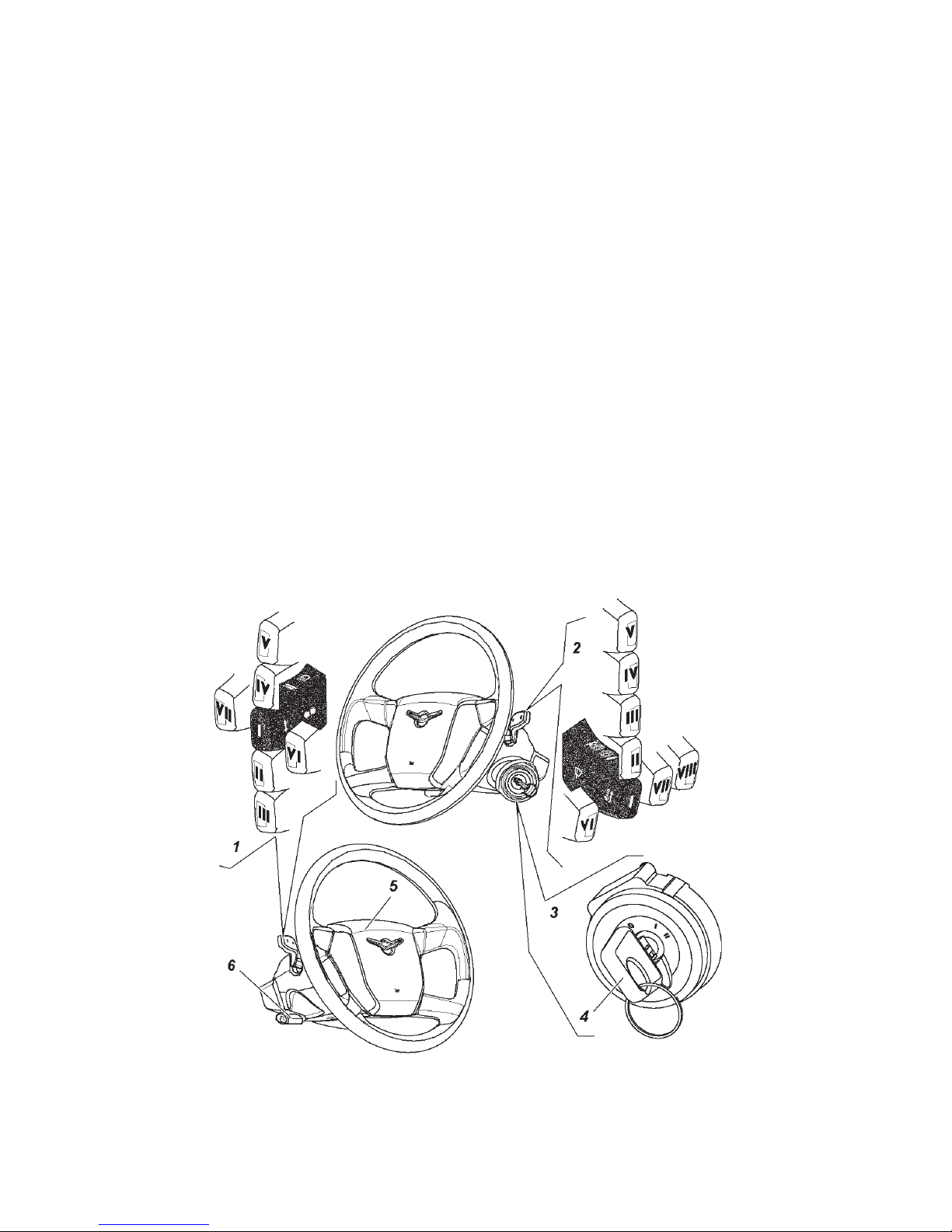
The steering column with the steering wheel, the multi-function
understeering switch, the ignition starter switch and the steering
column toward angle control lever are shown in Fig. 3.5.
1 — direction indicator and beam switch lever have the following
positions:
I — direction indicators are OFF, dimmers are ON, if forward
lighting is switched off by the vehicle light switch;
II — left direction indicators are ON (unstable position);
III — left direction indicators are ON (stable position);
IV — right direction indicators are ON (unstable position);
V — right direction indicators are ON (stable position);
VI — (pull) headlamp high beam flash, regardless of vehicle
light switch position (unstable position);
VII — (push) distance light is ON, if forward lighting is
switched on by the vehicle light switch (stable position);
Fig. 3.5 Steering column with the steering wheel, the steering column multifunction switches, the ignition starter switch and the steering column canting
angle control lever (see item description in the text)
Page 37

37
2 — wiper and washer lever, have the following positions:
I — wiper and washer are OFF;
II — windshield intermittent wiper is ON (unstable position);
III — windshield intermittent wiper is ON (stable position).
Intermittent wiper and adjustment of delay between brush strokes
is provided by the intermittent wiper, located in the relay and
fuse units:
- when switching the wiper understeering switch to the
intermittent mode, min. delay of (1.5...2.5) s is set;
- if it is necessary to set delay within the range between
1.5 s and (60±12) s, the switch lever shall be set to the "OFF"
position (pos. I), then wait for (set) the required delay, and
then the lever should be set again to the "intermittent wiper"
(pos. III);
- if wiper operation should be adjusted, the above specified
operation should be carried out again;
- after switching off the ignition lock or interruption in
intermittent wiper operation of over (75±15) s the set delay
values are not saved;
IV — windshield wiper constant mode (low speed) is ON
(stable position);
V — windshield wiper constant mode (high speed) is ON
(stable position);
VI — (pull) windshield wiper and washer are ON (unstable
position);
VII — rear screen wiper is ON (stable position);
VIII — (unstable position) when pushing the lever, the lift
gate window washer electric motor operates, when releasing the
lever, water supply is shut off.
3 — ignition starter switch has three positions:
0 — parking (stable position);
I — ignition ON (stable position);
II — starter ON (unstable position).
WARNING! It is prohibited to cut off IGN and remove the
key from the ignition starter switch while driving a motor vehicle.
Engine stoppage will lead to braking capacity reduction, and
upon removing the key the steering system shaft becomes blocked
by an anti-hijack device and the motor vehicle can no longer be
controlled.
Page 38

38
4 — ignition and door key.
Three keys are attached to the motor vehicle, each key is
designed to unlock door locks and to start up the ignition.
The transponder, an electronic chip that saves the unique
identification number, is embedded in the motor vehicle key
bow. The immobilizer blocks the engine start without code prereading from the transponder thus ensuring additional protection
against unauthorized use.
The key is removed from the lock only in position 0, in which
the locking device mechanism actuates and locks the steering
system shaft.
To lock the steering system when parked, set the key to position
0, remove it and turn the steering wheel in any direction until
it clicks, whic indicates that locking device catch has matched
with the groove of the steering wheel shaft stop sleeve.
When unlocking the steering system, insert the key to the
ignition switch and, swaying the steering wheel to right and left,
turn the key clockwise to position I.
In order to avoid accidentally switching on the starter with
engine on (key position II), the lock mechanism includes locking,
that enables engine re-start only after key is set to position 0
again.
5 — horn button.
6 — steering column tilt angle control lever. To change steering
column tilt angle, pull the lever down, move the column and
release the lever.
WARNING! Do not adjust steering column tilt angle when
driving a motor vehicle. After adjustment make sure that the steering
column is securely fixed in a new position.
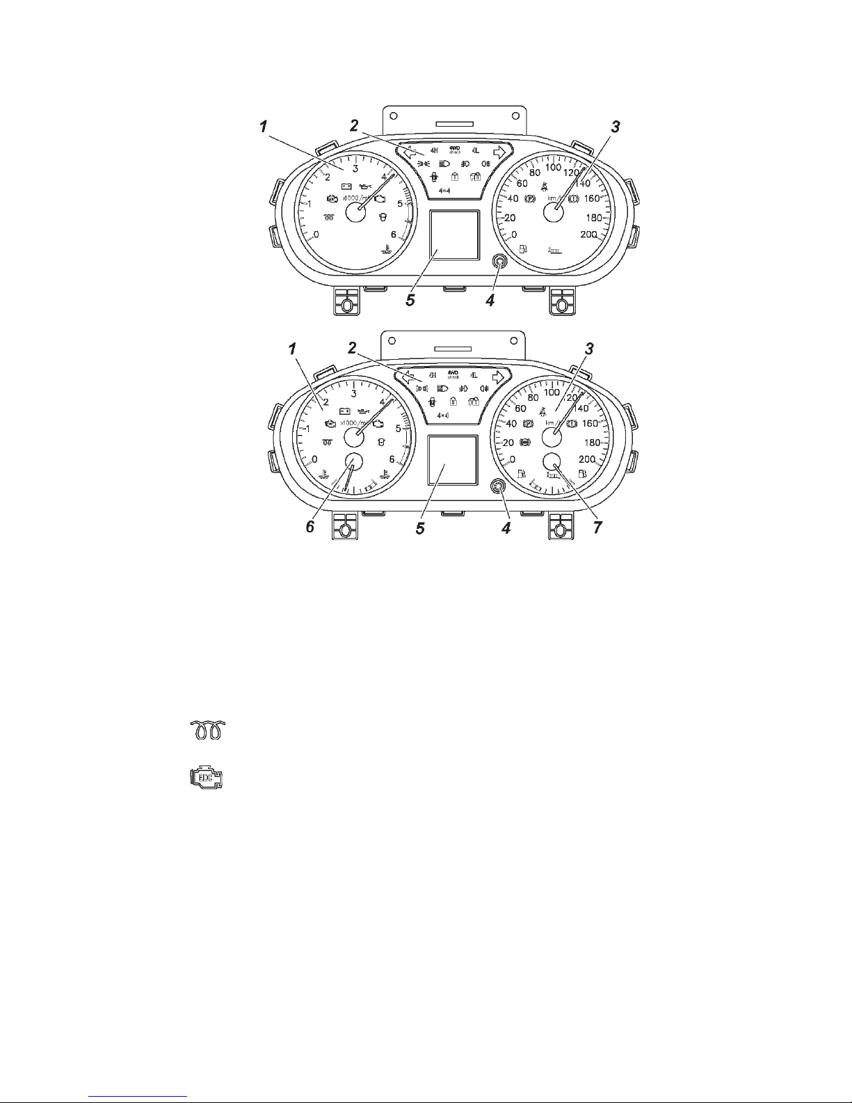
CLUSTER
Cluster is shown in Fig. 3.6.
Green and blue signal devices inform the driver of the normal
operation of the switched on system. Orange signal devices
warn a driver of the need to take measures to ensure the motor
vehicle's continued normal operation. Red signal devices warns
the driver of an emergency packs operation.
Motor vehicle operation with continuously lighted (at least
one) red signal device is not allowed.
Page 39
39
1 — tachometer with signal devices. The scale red range
indicates exceeding permissible rpm and engine operation in
emergency mode.
Indicators on the tachometer.
— diesel engine glow plugs ON signal device (yellow).
— “EDC” malfunction signal device of the diesel engine
control system (yellow). It lights up for 2-3 s for testing when
starting up the ignition and goes out. Signal device switching on
(continuously lit lamp or blinking lamp) indicates a malfunction of
the engine control system. In case of continuously lit lamp, if it
is not accompanied by significant deterioration of riding qualities,
a motor vehicle can be driven to the nearest authorized service
station of UAZ, PJSC to carry out diagnostic works. If the lamp
blinks, engine operation is not permitted, the motor vehicle must
be stopped and the engine must be shut off.
Fig. 3.6. Cluster (see item description in the text):
a — dual-needle:
b — four-needle
a
b
Page 40

40
Prolonged operation with the malfunction signal device switched on
can lead to malfunction of the elements of the engine control system.
— accumulator battery discharge signal device (red). If it
is lit with engine on, it indicates a lack of accumulator battery
charge.
— oil pressure warning signal device of the motor vehicle's
engine lubrication system (red). Signal device lights up after
starting up the ignition and goes out after starting the engine at
increased crankshaft rpm.
— complex microprocessor engine control system
malfunction signal device of the engine control system elements,
which affects the exhaust gas toxicity (yellow). It lights up when
starting up the ignition and goes out after starting the engine.
When the signal device switches on, it indicates a malfunction of
the engine components or the exhaust system, which affect the
exhaust gas toxicity level. When the signal device switches on, if it
is not accompanied by significant deterioration of riding qualities,
driving is permitted at low speed to the nearest authorized service
station of UAZ, PJSC, to carry out diagnostic works.
Prolonged operation with the malfunction signal device switched
on can lead to malfunction of the engine control system elements.
When switching on, the signal device starts blinking with
frequency of 5 Hz in case of engine control unit malfunction,
and also in case of immobilizer malfunction and using of an
unregistered code key (see section "Electronic anti-theft device").
— signal device of water in the fuel filter of a disel engine
motor vehicle (yellow).
— signal device of abnormal coolant overheating (red).
2 — signal device box:
— left direction indicator and hazard light ON signal device
(green).
— right direction indicator and hazard light ON signal
device (green).
— axle front engagement signal device (green). It lights
up after starting up the ignition and should go out if this mode
is not ON. It lights up when engaging the front axle at any gear
of the transfer case. For a motor vehicle with the transfer case
of UAZ, PJSC, the signal device is not used.
Page 41
41
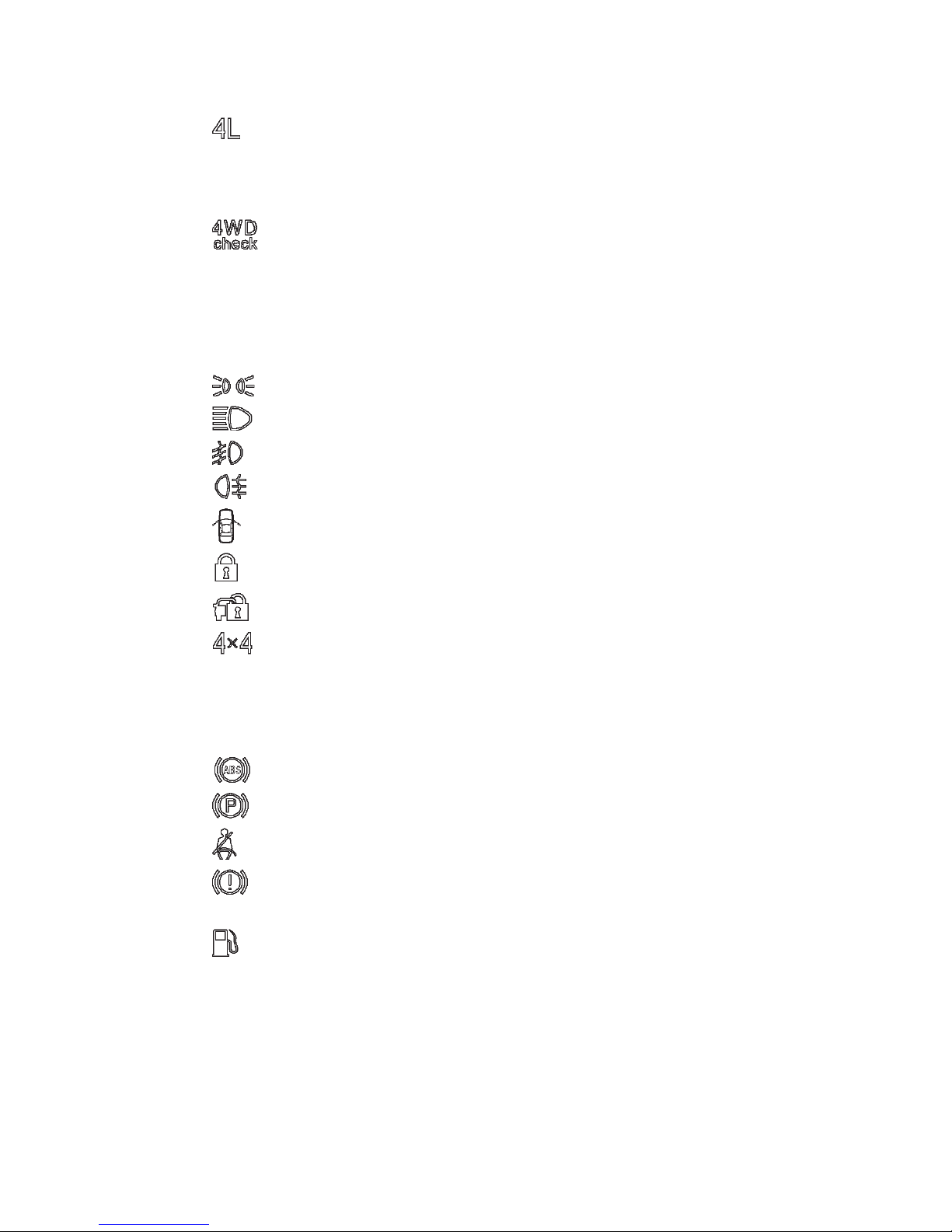
— front axle and underdrive "4L" engagement signal device
(green). It lights up after starting up the ignition and should go
out if this mode is not ON. For a motor vehicle with the transfer
case of UAZ, PJSC, the signal device is not used.
— transfer case malfunction signal device (yellow).
It lights up after starting up the ignition and should go out if
the system is in normal condition. If the indicator is still ON,
the all-wheel control system should be checked at the nearest
authorized service station. For a motor vehicle with the transfer
case of UAZ, PJSC, the signal device is not used.
— tail lamps ON signal device (green).
— distance lights ON signal device (blue).
— font fog lights ON signal device (green).
— rear fog light ON signal device (orange).
— door ajar signal device (red).
— security alarm system signal device (yellow).
— immobilizer ON signal device (yellow).
— 4-wheel drive ON (for the transfer case by UAZ,
PJSC).
3 — speedometer with signal devices.
Signal devices on the speedometer:
— brake ABS malfunction signal device (ABS) (yellow).
— park brake ON signal device (red).
— unbuckled seat belt signal device (red).
— service brake system and EBD malfunction signal device
(red).
— low fuel level signal device (yellow). It lights up when
less than 9 l of fuel is left in the right tank.
4 — trip computer switch. Switching over is performed by
pressing and turning the switch clockwise/counter-clockwise.
5 — LCD-display (depending on package) displays the following
functions of the trip computer:
Page 42

42
- coolant temperature in the engine (for dual needle cluster);
- fuel level in the fuel tank (for dual needle cluster);
- motor vehicle power supply voltage;
- motor vehicle total and daily mileage. Daily mileage counter
reset is performed by long (over 2 s) pressing the cluster switch;
- time of day (in 24-h format). To set the clocks, the "Clocks
setting" mode should be switched on in the trip computer. By
long pressing the cluster switch (over 2 s), the setting mode is
activated. Hours/minutes values can be set by turning the switch
clockwise/counter-clockwise. Switching over between hours/
minutes settings is performed by short (less than 1 s) pressing
the cluster switch;
- ambient temperature (depending on the package);
- date (in "XX month" format). To set the date, the "Date
setting" mode should be switched on in the trip computer. By
long pressing the cluster switch (over 2 s), the setting mode is
activated. Day, month and year can be set by turning the switch
clockwise/counter-clockwise. Switching over between day/
month/year/minutes settings is performed by short (less than
1 s) pressing the cluster switch;
- instantaneous fuel economy (l/100 km);
- average fuel consumption (l/100 km);
- fuel distance (in km);
- current motor vehicle speed;
- average motor vehicle speed
6 — coolant temperature indicator. Engine operation with
the indicator pointer in the red range is not allowed. Range of
values from 50°C to 130°C. Division value 10°C.
7 - fuel level indicator.
FLOOR STANDING BOX WITH BLOCKS AND
CONTROL KEYS
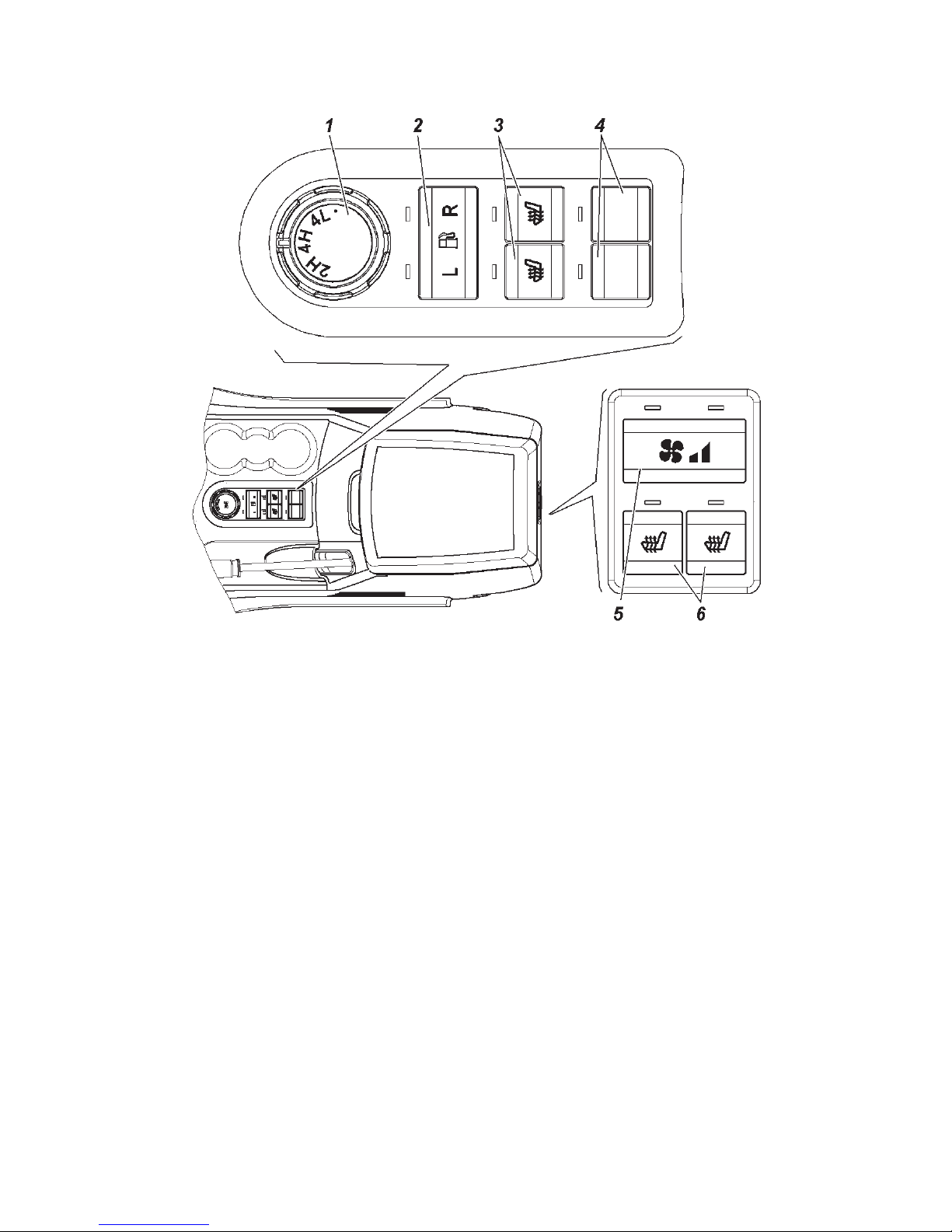
Floor standing box with unit and keys control for motor
vehicles with the "Dymos" transfer case is shown in Fig. 3.7.
1 — transfer case mode switch.
Modes:
2H — only back axle drive. This mode is used to drive over
dry hard-surface roads;
4H — all-wheel drive. This mode is used to drive over wet
or slippery hard-surfaced road, off-road or terrain;
Page 43
43
4L — all-wheel drive with underdrive. This mode is used to
overcome difficult choke points, for hill climbing (overcoming
downwards slopes) with high gradient, driving at low speed, to
increase drawbar pull, etc.
WARNING!
Switch manual gearbox modes only with engine on.
All-wheel drive "4H" mode switching ON/OFF shall be
performed both in a stationary motor vehicle and when driving in
cruise modes "along the straight line", without wheel slip.
Engage all-wheel drive in due time before entering a difficult
road section!
Switching the mode of all-wheel drive with underdrive "4L"
ON/OFF shall be performed only in a stationary motor vehicle!
There is no manual gearbox mode indication in the cluster
in the initial position "2H", only the back axle is driven.
Fig. 3.7. Floor standing box with unit and keys control
(see item description in the text)
Unit 1
Unit 2
Page 44

44
Driving mode change 2H=> 4H:
To switch on all-wheel drive "4H" mode:
- release accelerator pedal;
- press and hold the clutch pedal;
- set the handle from the "2H" position to the "4H" position.
If switching is successful, the symbol is switched in the
cluster;
- release the clutch pedal.
If:
- efforts are made to switch all-wheel drive mode ON at the
moment of significant back wheel slip against the front wheel;
- a motor vehicle is driven with a pressure difference in the front
and back wheels exceeding the pressure difference specified in the
Manual;
- immediately before switching on turning with minimum possible
radius has been performed, or an effort to switch on is made
immediately when turning;
- in other exceptional cases, when front wheel and back wheel
drives will have different rpms at the moment of engagement
all-wheel drive; system switching over to the emergency mode is
possible, of which the simultaneous switching on of signal devices
is an indicator, , and in the cluster. With that only
the back wheel drive remains active.
In this case, to switch the "4H" mode, it is necessary to set the
switch to the "2H" position and the "4H" mode should be switched
on again.
Driving mode change 4H=> 2H
To switch all-wheel drive mode OFF (engagement of back
axle drive "2H") it is necessary to:
- release accelerator pedal;
- press and hold the clutch pedal;
- set the handle from the "4H" position to the "2H" position.
If switching over is successful, the symbol is switched off in
the cluster;
- release the clutch pedal.
Driving mode change 4H=> 4L
To switch on the mode of all-wheel drive with underdrive 4L
(beforehand the all-wheel drive "4H" mode must be switched
on), it is necessary to:
Page 45

45
- stop the motor vehicle;
- press and hold the clutch pedal;
- set the switch handle from the "4H" position through the
"4L" position to the unstable position "•" and hold it until the
signal device in the cluster switches on;
- when the signal device switches on in the cluster,
release the switch handle (the switch handle self-resets to the
"4L" position);
- start driving, smoothly releasing the clutch pedal.
Driving mode change 4L=> 4H
To switch on the mode of all-wheel drive with underdrive it
is necessary to:
- stop the motor vehicle;
- press and hold the clutch pedal;
- set the switch handle from the "4L" position to the "4H"
position;
- when the signal device switches on in the cluster, start
driving, having smoothly released the clutch pedal.
2 — fuel level sender switch in the tanks. Senders are switched
over by short pressing the central key zone. The signal device
lights up according to the connected sender: "L" — left tank,
"R" — right tank.
3+ — front seat heater switches.
4 — redundancy switches.
5+ — auxiliary heater speed control switch.
Low speed of the auxiliary heater electric motor is switched
on by short pressing the switch, at which point the left signal
device above the switch lights up. When the switch is short
pressed again, the high speed auxiliary electric heater motor
is switched on, additionally the right signal device lights up.
By short pressing the switch or when the key is removed, the
auxiliary heater and signal devices are switched off.
6+ — back seat heater switches. By short pressing the switch,
the heating of the respective seat switches on and the signal
device lights up. Seat heating and the signal device are switched
off when the switch is pressed again or when the key is removed.
Page 46

46
Motor vehicle's electronic anti-theft system with the engine
control unit ME 17.9.71 (Engine ZMZ-40906)
The anti-theft system set includes three ignition keys, in whose
bows the transponders are embedded. The keys are equal in terms
of their functional capabilities. The system allows eight ignition
keys to be registered. The prerequisite for system operation is
the registration of three ignition keys.
The system can be in the "neutral", "taught" and "key upgrading"
states with respect to ignition key registration.
"Neutral" state — after replacing the engine control unit at a
service station, the system carries out automatic registration of
the ignition keys, for this purpose the ignition should be started
up by each key one by one.
Motor vehicle engine start is not possible until three keys are
registered automatically and the system state changes to "taught".
"Taught" state — three keys are registered successfully.
"Key upgrading" state — after the procedure of switching
over to this state, the system registers (re-registers) the required
number of the ignition keys.
When starting up the ignition without successful key registration
and successful key code recognition the engine start is not possible.
With regard to prevention of unauthorized motor vehicle use
the system can be in the "ON" and "OFF" states.
"ON" state — the immobilizer locks engine start. The
immobilizer turning-on signal device is continuously switched
ON.
The system switches over to this state in the following cases:
- if the engine is not started for 25 s after starting up the
ignition and successful key code recognition;
- if after starting up the ignition the key code is not recognized
(the system will store the trouble code, which can be read out
using a diagnostic tester);
- if the system is in the "neutral" state and key registration
is not carried out;
- if the system is in the "taught" state and an unregistered
key is used;
- if the system is in the "key upgrading" state and key
registration (re-registration) is not carried out;
- in 25 s after starting up the ignition;
Page 47
47
- in 25 s in case of engine stop and there are no efforts to
re-start the engine;
- after power failure.
"OFF" state — the immobilizer does not prevent engine start.
The immobilizer ON signal device
is OFF.
The system switches over to this state (disarming) after
starting up the ignition provided that the key code is recognized
successfully.
The ignition key (transponder) can be in the "initial",
"registered" and "faulty" states.
"Initial" state — the ignition key, handed over by the
manufacturer, which is not registered in the system.
"Registered" state — the ignition key, registered in the specific
system. After successful recognition of the key, engine start is
possible.
"Faulty" state — the ignition key, whose code was not
recognized by the system at starting up the ignition. Motor
vehicle engine start is not possible.
WARNING! To register (re-register) the keys, any two keys that
were previously registered during the last session should be used.
Take all necessary measures to prevent key loss.
It is not recommended to start the engine using a key registered
in this system that is in the same bunch with other keys, both
registered and unregistered.
After starting up the ignition (Fig. 3.5), the immobilizer
turning-on signal device lights up for 1.5 s in the test mode.
Then the signal device initiates the following state of the antitheft system until engine starts:
- the system is in the "ON" state or the key registration procedure
is not completed — the signal device
is continuously ON;
- the system is in "OFF" state or the key registration procedure
is completed — the signal device
is OFF;
- when performing the key registration procedure, the signal
device
switches on 5 times for a period of 1 s (0.5 s —
OFF/0.5 s — ON);
- the system is in the "neutral" state — the signal device
switches on 3 times for a period of 3 s (1.5 s — OFF / 1.5 s —
ON).
Page 48

48
- the system is in the "key teaching" state — the signal device
switches on 4 times for a period of 3 s (1.5 s — OFF/1.5
s — ON).
Keys registration. Only ignition keys that are in "initial" and
"registered" states (previously registered in the system) are subject
to the registration. Keys registered in other systems cannot be
re-registered in this system. The registration is only possible using
any two keys that are registered in the previous key registration
session.
Key registration with the system in the "taught" state is used
to ensure that the motor vehicle owner have additional available
ignition keys (without deleting codes registered in the previous
ignition key registration session).
In order to register a key it is necessary to carry out the
following operations:
- start up the ignition using one of the registered keys, turning
it into position I (Fig. 3.10) of the ignition starter switch;
- make sure that ignition is started up, key code is recognized
(the immobilizer turning-on signal device is OFF);
- 10 seconds after starting up, shut ignition, turning the key
into the 0 position (Fig. 3.10);
- For 10 s start up the ignition using another registered key,
make sure that the ignition is started up, the key is recognized;
- 10 s after starting up, shut ignition. The immobilizer turningon signal device
starts blinking, the system is ON;
- For 20 s (signal device blinking time) start up the ignition
using the key to be registered. Registration is completed if in
5 seconds the signal device goes out. If the signal device is lit
continuously (without blinking), the key registration is considered
incompleted.
If a larger number of keys should be taught, repeat the key
registration procedure.
WARNING! Switching on the starter or violation of the specified
time intervals or switching OFF the power supply system prevent
logging on the key registration procedure, and if the system is already
in the procedure, interrupt all further key registration operations.
Key re-registration is used if at least one key is lost, and
to register additional keys (by deleting codes of the previously
registered keys).
Page 49

49
For this purpose it is necessary to switch the system over to
the "key upgrading" state and re-register keys:
- start up the ignition using one of the registered keys, turning
it into position I (Fig. 3.10) of the ignition starter switch;
- make sure that ignition is started up, key code is recognized
(the immobilizer turning-on signal device
is OFF);
- 10 seconds after starting up, shut ignition, turning the key
into the 0 position (Fig. 3.10);
- For 10 s start up the ignition using another registered key,
make sure that the ignition is started up, the key is recognized;
-10 s after starting up, shut ignition. The immobilizer turningon signal device
starts blinking, the system is ON;
- For 20 s (signal device blinking time) press the accelerator
pedal. When the system recognizes full pressing of the accelerator
pedal, the The immobilizer turning-on signal device
is OFF;
- keep the accelerator pedal pressed for 60 s. After that the
immobilizer turning-on signal device starts blinking;
- For 20 s (signal device blinking time) start up the ignition
using the key to be registered (not the first and not the second
registered key). The immobilizer turning-on signal device is
continuously lit. Release the accelerator pedal. Key registration is
completed if in 2 s the signal device goes out. If the signal device
starts blinking, the key registration is considered incomplete and
the registration process is interrupted;
- 10 s after starting up the ignition, shut ignition and remove
the key from the ignition starter switch.The immobilizer turningon signal device will blink for 20 s. To register additional keys,
proceed with the previous operation;
- to finish the key registration, start ignition using the second
(from the start of the procedure) registered key. The immobilizer
turning-on signal device continues blinking for 2 s and then
switches OFF;
- 10 s after starting up the ignition, shut ignition and remove
the key from the ignition starter switch. The immobilizer turningon signal device starts blinking;
- For 20 s (signal device blinking time), start up the ignition
using the first (from the start of the procedure) registered key.
The signal device switches OFF. After that, the system deletes
all key codes registered during the previous teaching session
and registers all keys used in the current registration procedure
Page 50

50
(the first, the second registered keys and additional keys). Key
registration is completed if the signal device switches ON and
goes out in 2 s.
If key registration is unsuccessful, the immobilizer turningon signal device will continue blinking and the system will be
locked until the ignition is started up using any of the registered
keys.
WARNING! Switching on the starter or violation of the specified
time intervals or switching OFF the power supply system prevent
logging on the key re-registration procedure, and if the system
is already in the procedure, interrupt all further key registration
operations.
POWER PACK CONTROL SYSTEM+
The system includes the control unit (CU), the driver side
door module (DSDM) and two keys with a remote control panel
(RCP).
Description of the electronic anti-theft system, key registration
and system operation is shown above in the chapter "Motor
vehicle electronic anti-theft system...".
Warning. Using the RCP in the absence of obstruction, it is
possible to control the electrical interlocking system in the front,
from the left and right side of the motor vehicle at a distance of 10
m, at rear — at distance of about 6 m.
To prevent theft, use remote control in close proximity to the
motor vehicle.
The control unit records, saves and displays the detected
malfunctions of the electrical interlocking system upon request of
the diagnostic tester that has the respective software.
Do not subject the RCP to the action of increased electromagnetic
emission.
To prevent malfunction, protect the RCP against detergents,
fuels, oils and lubricants, water.
The electrical interlocking system allows up to four RCPs to be
taught. When working with the electrical interlocking system the
RCPs are equal in terms of functional capabilities.
The teaching and educable control panel shall be separated from
the shared bunch of taught and non-taught RCP and ignition keys
with transponders when teaching the RCP.
Take measures to prevent RCPs loss.
Page 51
51
It is prohibited to operate the system if there is a possibility
of the ingression of corrosive liquids, acids, water, oil and petrol
in the CU, DSDM and RCP.
System functions:
- central locking and unlocking with the key;
- central door locking and unlocking from the inside of
interior;
- door locking and unlocking from the RCP depending on
the motor vehicle package;
- side door window lifting and lowering control;
- outside rear view mirror position adjustment control;
- interior lighting control (polite lighting) depending on the
motor vehicle package;
- intrusion alarm system;
- motor vehicle search in an unlighted parking place;
- "Panic" signalling and prompt alarm;
- system trouble diagnosis through the motor vehicle data
link connector.
Control System Operation Procedure
Door locks locking and armed mode switching on using the RCP
To lock door locks and switch armed mode ON it is necessary
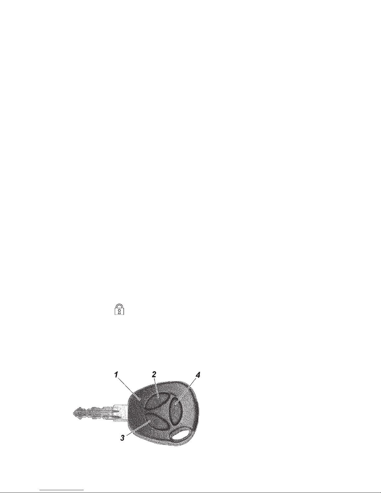
to short press button 3 (Fig. 3.13) on the RCP. All side door
locks and the lock of the T/gate are locked, the system switches
over to the armed mode that is indicated by a single blink of
the T/signals and a slow blinking of the signal device system in
the cluster
.
If any door, the cowl or the T/gate are opened when switching
armed mode on, the T/signals blink three times and a single horn
is given. In order to include the opened areas into the security
zone they must be closed.
Fig. 3.13. Key with remote
control panel:
1 — emission confirmation and
control panel battery discharge
indicator; 2 lock unlocking and
alarm switching off button; 3 —
lock locking and alarm switching
on button; 4 — horn button
Page 52

52
Door locks unlocking and armed mode switching off using the
RCP
To unlock all door locks and the T/gate lock and switch armed
mode OFF it is necessary to short press button 2 on the RCP.
Switching armed mode OFF is accompanied by a double blink
of the T/signals and interior lighting switching ON. If violations
of the security zone for the whole security period were detected
(Alarm actuated), a single horn will be given in addition to T/
signal blinking.
If after door unlocking and switching armed mode OFF
none of side doors or the T/gate are opened and the ignition
is not started up, in 30 seconds all doors will be automatically
locked again and the system will automatically switch over to
the armed mode. The possibility of automatically switching over
to the armed mode with door locking is indicated by frequent
blinking of the system's signal device in the cluster
.
Unlocking the door locks from the RCP with side door window
lowering
Unlocking of all side doors locks and the T/gate l o c k
with automatic side door window opening is carried out by
pressing the respective RCP button and holding it pressed till
the window starts moving (about 2-3 seconds). The system
carries out operations specified in the above mentioned items
to unlock door locks and then carries out automatic moving of
side door window to open — firstly front windows, then back
windows.
Every window movement is stopped automatically when
reaching the limit stop in the extreme position or all window
movement is stopped simultaneously by pressing any RCP button.
Movement of side door windows toward closing when locking
the door locks through the system is not to be carried out in
order to comply with the requirements of the international safety
rules.
Locking/unlocking locks from outside the motor vehicle without
switching on armed mode
To lock the door locks without switching to armed mode, it
is necessary to lock by turning the key in the driver side door
key hole clockwise. The locks of all side doors and the T/gate
lock are locked without armed mode switching on.
Page 53
53
This type of locking is not accompanied by T/signal blinking.
Door locks are unlocked the same way, the only difference
is turning the key counter-clockwise.
Fast driver side door lock unlocking
The system can be switched over to the fast driver side door
unlocking mode when, by single pressing button 2 of the RCP
or turning the key in the driver side door key hole, only the
driver side door is unlocked and, when pressing button 2 on the
RCP or button 2 (Fig. 3.14) of the DSDM again, all other side
doors and the T/gate are unlocked.
To switch on/off the fast unlocking mode it is necessary to
press button 2 of the DSDM max. 1 second after starting up
the ignition and hold it pressed (for at least 3 seconds) until
the characteristic sound of the door locks triggered to open.
If subsequently the system should be switched over to the
standard unlocking mode it is necessary to repeat the above
mentioned procedure.
Searching for a motor vehicle in an unlighted parking place
By single pressing and holding button 4 of the RCP (Fig.
3.8) the system blinks with T/signals two times, gives one horn
and switches interior lighting ON for about 25 s.
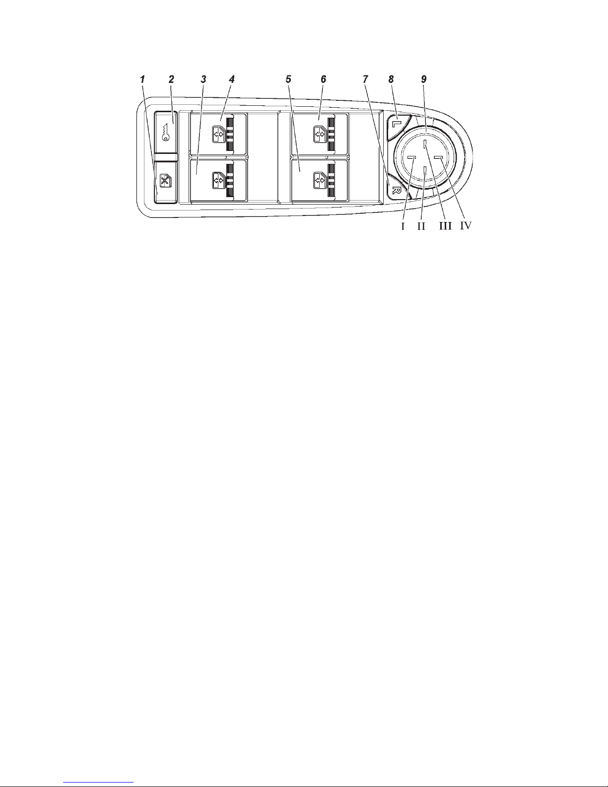
Fig. 3.14. Driver side door switch module with multiplex control:
1 -passenger door descending window glass guide interlocking switch; 2 — central
door locking switch (except for UAZ CARGO); 3 — right T/gate descending
window glass guide control switch; 4 — left T/gate descending window glass
guide control switch; 5 — right front door descending window glass guide control switch; 6 — driver side door descending window glass guide control switch;
7 — right mirror selection switch; 8 — left mirror selection switch; 9 — outside
rear view mirror position control switch (except for UAZ CARGO): I — mirror
down; II — mirror right; III — mirror left; IV — mirror up
Page 54

54
Remotely switching alarm system ("Panic") ON
To switch alarm system ON remotely, it is necessary to
press button 4 of the RCP twice or hold it pressed for at least
2 seconds. The alarm system switches ON for 5 s. To switch it
OFF, press any button of the RCP.
Switching prompt alarm ON
Switch prompt alarm ON is only possible with started up
ignition. Switching ON is performed by pressing button 4 of
the RCP and holding it for at least 2 s. To switch prompt alarm
OFF, press any button of the RCP.
Locking and unlocking central door locks from the interior
Locking all door locks (including the T/gate) from the motor
vehicle interior is possible using 2 methods:
- sink the interlocking switch in the driver side door to lock,
and pull the interlocking switch in the driver side door to unlock;
- press switch 2 (Fig. 3.14) of the DSDM. Every press either
locks or unlocks the locks.
The central locking has door lock overheating protection.
If locking or unlocking is performed many times over a short
period of time, the system stops responding to switch pressing. If
it has happened, the switch should not be pressed for some time
(depends on overheating degree), after that, system availability
will be fully recovered. To ensure safety, the last command is
always the unlock command.
In the fast unlocking mode, when opening the driver side door
with the key, only the driver side door is unlocked, to unlock
passenger doors and the T/gate press button 2 of the RCP or
switch 2 of the DSDM
Side door window position control
Position of all side door windows is controlled in the same
way.
Window position is controlled by the switches located on
the armrests of the respective motor vehicle doors. Side door
window positions are controlled by moving switches 3, 4, 5, 6
(Fig. 3.14) on the driver's door armrest.
Button 1 of the DSDM allows control of passenger door
window positions (all three passengers doors) from the switches
installed on the passenger door armrests to be disabled. If
Page 55

55
disabling mode is activated, the symbol on button 1 has yellow
illumination. Pressing the button again cancels disabling, etc.
If a driver and a passenger simultaneously control any door
window position, the command from the DSDM switches has
priority.
If passengers simultaneously control front and back windows
of the right side doors, a window control command from the
right front door switch has priority.
The side door window position control subsystem has
overheating protection. If window movement commands are
issued many times, after a while the subsystem stops responding
to switch pressing. If it has happened, the respective window
control switch should not be pressed for some time (depends
on overheating degree), and after that, system availability will
be fully recovered.
Side door window position is controlled only with the ignition
started up and 30 seconds after ignition is shut if no motor vehicle
side doors were opened.
Window position control from the switches in the doors is
not possible when the armed mode is switched ON.
Operation of exterior mirror adjustment electric drive
Left and right exterior mirror electric drive is controlled by
single switch 9 (Fig. 3.14), located in the DSDM. Selecting the
mirror to be adjusted according to the commands from the switch
is made by one of the switches 7 or 8 of the DSDM — mirror
selection buttons. Simultaneous left and right mirror adjustment
is not possible.
Indication of readiness to adjust of the selected mirror is
yellow illumination of the respective selection button. Mirror
adjustment is disabled automatically (the mirror selection button
yellow illumination goes out), if switch 9 is not pressed for over
10 seconds and the mirror selection switches have not been
pressed.
Exterior mirror position adjustment is possible only with the
ignition started up or 30 seconds after shutting ignition if no
side doors motor vehicle were opened.
Mirror control is not possible when armed mode is switched
ON.
Page 56

56
System operation in armed mode
When armed mode is switched ON the system monitors the
states of the following security zones:
- side doors;
- cowl;
- T/gate;
- ignition starter switch;
- driver side door lock;
- accumulator battery voltage.
If any of the following actions take place in the armed mode:
- opening of any side door;
- cowl opening;
- T/gate opening;
- ignition start up;
- driver side door unlocking;
- accumulator battery connection after its disconnection,
the alarm system switches ON as T/signals light alarm and an
audible standard motor vehicle horn alarm for about 30 s.
Single pressing any button on the RCP when the system is
in alarm mode leads to interruption of alarm signal sending but
the system remains in armed mode. Armed mode is switched
OFF after button 2 on the RCP is pressed.
RCP battery replacement
A lithium battery, CR2032 type, is installed in the RCP, its
initial voltage is 3V. If the RCP's supply voltage is within normal
range, indicator 1 flickers with every pressing of any button on
the control panel. If the indicator lights up with two short flickers
or does not light up at all when pressing any button, the battery
should be replaced.
For this purpose, unscrew screw 1 (Fig. 3.15) from the housing
side, opposite to the control buttons; using a flat screwdriver,
separate the housing halves; pull the board out of the housing;
replace battery 2 observing connection polarity; insert the board
into the housing; clip the housing's halves and tighten the screw.
RCP code re-synchronization
When the control panel's buttons are pressed out of the radio
channel range, the floating code counter in the control panel falls
out of synchronization with respect to the counter in the system
control unit. If the number of control panel button pressings
Page 57
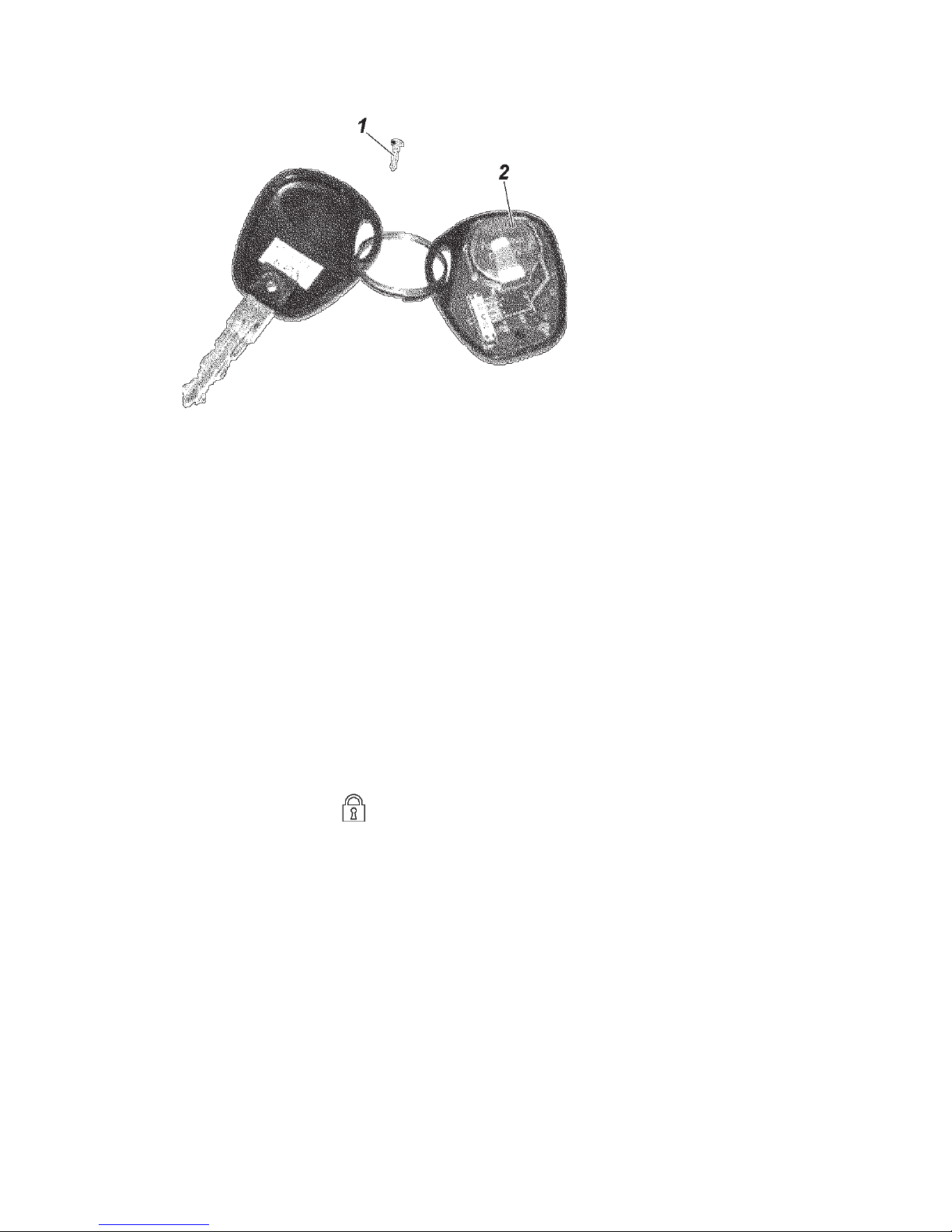
57
outside the system reception signal range has exceeded 1000,
the system stops responding to control panel commands. In this
case the full system teaching procedure should be carried out.
Full system teaching
In case of full system teaching, all previously recorded control
panel codes will be deleted, and new codes will be recorded in
their place. Full teaching is performed when one of the control
panels is lost and it is necessary to delete it from the system.
To log on the teaching mode, any RCP that was taught in the
system and the synchronization counter which is synchronized
with the control unit are needed. The RCP with which teaching
has been initiated becomes educative in this teaching session.
When the teaching procedure is violated, the system logs out
of the teaching mode without any results saved and the system
status indication in the cluster goes out.
Full teaching is performed in the following order:
1. Deactivate system security system;
2. Leave one of the doors open;
3. Start up the ignition;
4. Max. 1.5 s after starting ignition, press button 4 on the
control panel to be taught and hold it pressed;
5. Wait until the system status signal device in the cluster
starts blinking fast, indicating the teaching process has started
(about 3 s after pressing button 4);
6. Max. 3 s after the indicator starts blinking, holding button
4 pressed, press button 2 one time. The system status signal
device stops blinking and is continuously lit. Release button 4;
Fig. 3.15. Remote
control panel:
1 — screw; 2 — replace
battery
Page 58

58
7. In max. 3 s cycle the ignition;
8. Max. 3 s after starting up the ignition press button 4 on
the control panel to be taught and hold it pressed;
9. Wait until the system status signal device in the cluster
starts blinking fast (about 3 s after pressing button 4);
10. Max. in 3 s after the indicator starts blinking, holding
button 4 pressed, press button 2 one time. The system status
signal device stops blinking and is continuously lit (without
blinking). Release button 4;
11. In max. 3 s cycle the ignition;
12. Repeat items 8-11 to teach other RCPs, the number
of which can be from 0 to 3. The same control panel in the
teaching mode is registered in the system only once, therefore
if the system detects that this RCP has already been registered
in the current teaching mode, the teaching mode is logged out
without data saving;
13. When the required number of RCPs are registered in the
system, it is necessary to finish teaching using the teaching key.
Do do so, in max. 3 s after starting up the ignition, press button
4 on the teaching control panel and hold it pressed. Successful
completion of teaching is accompanied by triple T/signal blinking,
a short horn, and system status signal device blinking in the
cluster, the number of flashes of which is equal to the number
of RCPs to be taught in the current teaching mode.
Fast system teaching
The difference between fast system teaching and full teaching
is that the already taught RCPs are not deleted. New RCP codes
are written in free memory cells, the total number of the taught
keys shall not exceed four. For fast teaching it is necessary to
deactivate the security system and close all doors, and then
perform items 3-13, described in section "Full system teaching".
DEFENSIVE PARKING SYSTEM+
Defensive parking system (DPS) is designed to warn a driver
of obstructions (objects), located out of driver's sight with a horn
when motor vehicle is driving in reverse with max. speed of
5 km/h.
DPS significantly facilitates driving motor vehicle in reverse
and parking in confined spaces, obscured conditions, during
hours of darkness and with dirty windows and mirrors.
Page 59

59
Warning! Defensive parking system is optional equipment that
facilitates motor vehicle driving but does not drive a motor vehicle
itself, therefore the manufacturing plant is not responsible for any
possible damages when driving in reverse.
Operation procedure
1. Putting the system into operation.
When starting up the ignition and with reverse gear engaged
the system should be set into operation automatically, and a
short high-tone horn is given with a duration of 0.2-0.3 s. If a
hindrance is within the detection area, the system informs the
driver of it with an intermittent or continuous signal depending
on a distance to the hindrance. The motor vehicle may be driving
in reverse or be stationary.
2. System diagnosis.
When the system is switched on (see item 1), a short high-tone
horn is given, then the control unit performs an integrated check
in order to detect faulty sensors or other system malfunctions.
If a faulty sensor or other system malfunction is detected after
the switching on signal, a continuous low-tone horn is given for
3 s, then:
- if sensor A (left, as viewed in the direction of motor vehicle
motion, Fig. 3.11) or its circuit is faulty, the system indicates a
faulty sensor with one low-tone horn with a duration of 0.5 s;
- if sensor B or its circuit is faulty, the system indicates a
faulty sensor with two short low-tone horns with a duration of
0.5 s and interval of 0.3 s;
- if sensor C or its circuit is faulty, the system indicates a
faulty sensor with three short low-tone horns with a duration of
0.5 s and interval of 0.3 s;
- if sensor D (right, as viewed in the direction of motor
vehicle motion) or its circuit is faulty, the system indicates a
faulty sensor with four short low-tone horns with a duration of
0.5 s and interval of 0.3 s;
- if the control unit is faulty, a low-tone horn is given with
a duration of 2s.
- if several sensors or circuits are faulty, the system indicates
it by sequentially listing faulty sensor numbers.
After malfunction alarm, the system switches off.
3. Audible hindrance alarm.
Page 60
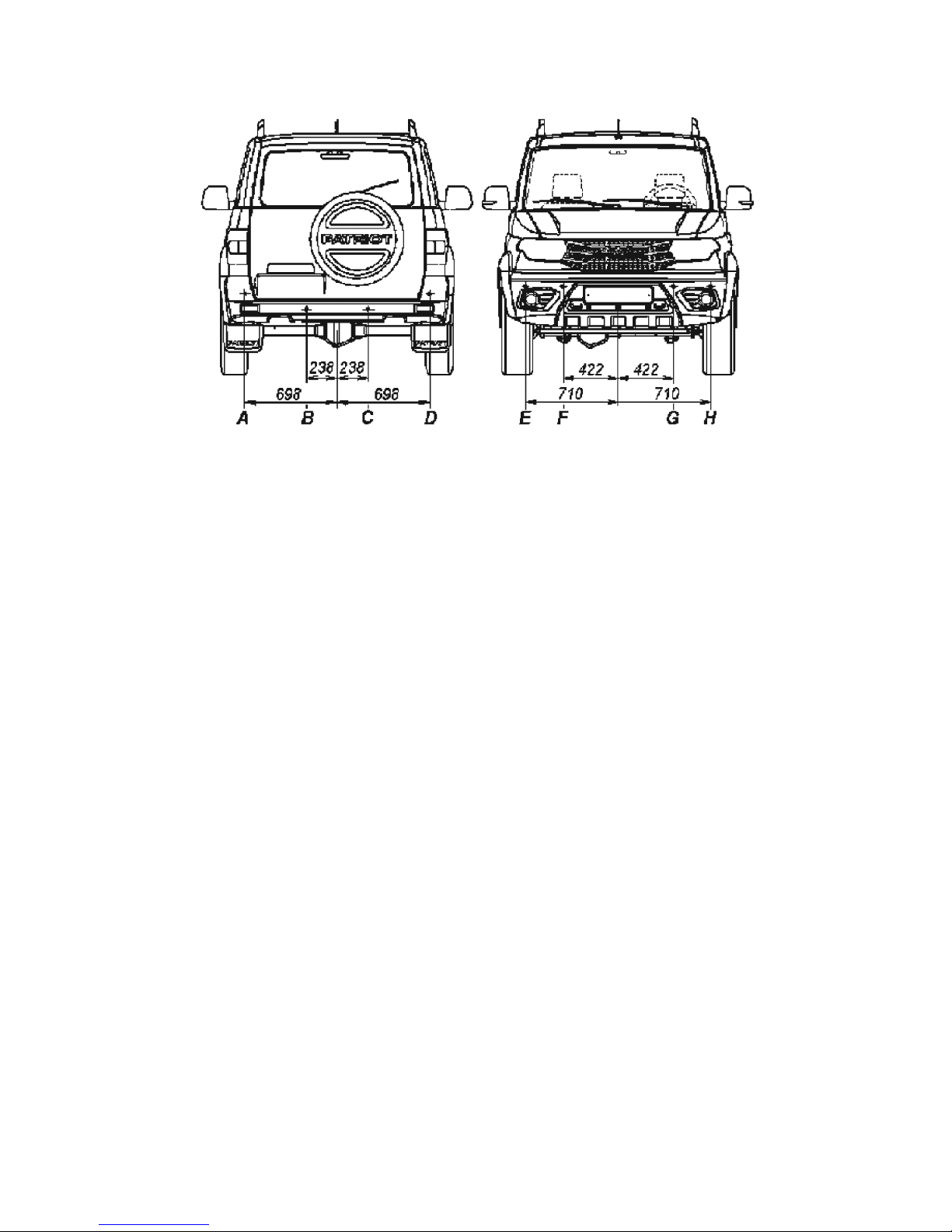
60
When a motor vehicle approaches a hindrance, an intermittent
acoustic tone signal is given with tone frequency of 1-3 kHz.
The interval time between tone "sendings" reduces as the
distance to the hindrance reduces, up to continuous horn at a
distance of 60 + 5 cm and less.
WARNING! Unauthorized modifications to the DPS circuit
diagram and design are strictly prohibited.
When operating, keep the parking system sensors (PSS) clean,
do not subject them to mechanical impacts. PSS surface should
be cleaned of contaminations using a soft cloth moistened with a
mild soap solution. When removing contaminations from the PSS
surface avoid applying pressure to its central part in order to prevent
damages.
DPS may not give a horn for a hindrance from behind in the
following cases:
- hindrance is located at a distance of less than 0.1 m;
- hindrance is a sharp or thin object (ropes, chains), posts with
diameter of max. 10 cm;
- hindrance surface of absorbent material ultrasound (snow,
clothes or other porous materials);
- hindrance has smooth round shape or is smooth inclined
surface (heavy inclination);
- the system's sensors are covered with snow, ice or dirt;
Fig. 3.16. DPS sensor layout:
A, B, C, D — rear sensors;
E, F, G, H — front sensors
Page 61

61
- the motor vehicle moves in reverse with speed of over 5 km/h;
- system's elements or electric circuits are faulty.
DPS may give a faulty horn of hindrance from behind in the
following cases:
- when installing optional equipment or changing motor vehicle
bumper installation height;
- with increased noise sources within the DPS range of action;
- chattering drive (unmetalled road, irregularities, sloped roads,
tall grass);
- under conditions of heavy rain and plenty of spatters;
- when hauling a trailer;
- contaminated system sensors (snow, ice or dirt);
- when the rear bodywork is overloaded
- malfunctions of system's elements or electrical circuits.
Defensive parking system's elements belong to non-repairable
items.
"AUTOCRUISE" AND
"OVERSPEED LIMITER" SYSTEM
"Autocruise" (AC) and "Overspeed limiter" (OSL) system
OSL is designed to maintain the set vehicle speed automaticlly
without
the driver pressing the accelerator pedal and for automatic
limitation of the permissible vehicle speed, set by the driver.
The AC and OSL system includes the following devices:
- electronic engine control unit (ECU). Includes AC and
OSL function algorithm to control engine torque;
- cluster (CL). Displays the current state of AC and OSL
functions;
- network gateway. Receives sending through the LIN bus
and transmits message on the steering system keys unit to the
controller area network;
- current collector. Transmits signals from the steering system
keys unit to the network gateway through the LIN bus;
- steering system keys unit, Fig. 3.17. Serves to control AC
and OSL functions;
- hydromodulator ESP9. Transmits motor vehicle speed and
longitudinal acceleration signals to the controller area network.
Page 62
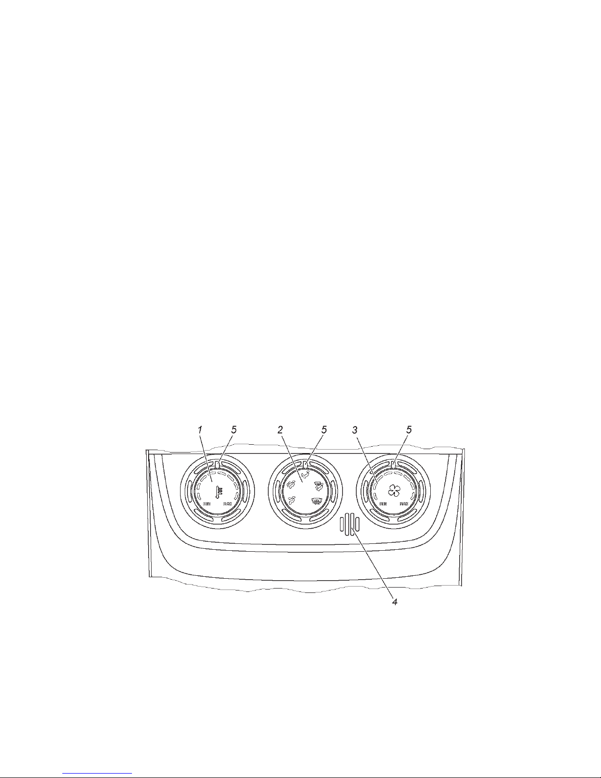
62
VEHICLE INTERIOR AND BODY EQUIPMENT
Interior heating, ventilation and conditioning
The vehicle is equipped with heating-and-ventilating unit
and climate control unit produced by Sanden. The units are
controlled by control board 5 (Fig. 3.1, 3.2).
Control panel (Fig. 3.12) is meant for maintaining of
temperature in the interior set by the driver and performs the
following functions:
- Motoreducer control of the heatr flaps;
- Ensuring the ability to operate the unit in "Manual" mode;
- Ensuring the ability to operate the unit in "AUTO" mode;
- Ensuring the ability to operate the unit in "Intensive
windscreen heating" mode;
- Ensuring the ability to operate the unit in "Interior
preheating" mode;
- Unit fan control capacity;
- Motoreducer control of the recirculation flap.
When actuating the tail lamps, all markings on the switches
of the control panel are illuminated with green light. The same
happens when the ignition is turned on or off.
Fig. 3.12. Heater control panel:
1 — rotary switch for adjusting the temperature of the air incoming to the interior (in "Manual" mode) / setting of the interior air temperature (in "AUTO"
mode) with a built-in indication system; 2- rotary switch for distribution of air
currents (controls the motoreducer of the front and rear heater flaps) with a
built-in indication system; 3 — rotary switch for controlling the fan speed of the
climate control unit with a built-in indication system; 4 — interior temperature
sensor; 5 — rotary switch marker
Page 63

63
In addition, rotary switch 2 has yellow illumination, which
indicates malfunctions in heating-and-ventilating unit and
climate control unit control system (this function is activated only
when the control panel is scanned with certifier via diagnostic
K-Line channel) detected by the control panel. It also indicates
"Interior preheating" mode.
"Interior preheating" operation mode is indicated with blinking
yellow illumination on rotary switch 2. The blinking period of
the illumination is 4.5 seconds:
- turned on 1.5 sec / turned off for 3 sec, when the tail lamps
are turned off;
- yellow illumination turned on 1.5 sec / green illumination
turned on 3 sec, when the tail lamps are turned on.
If the control panel has malfunctions, they are indicated
with switching on/off yellow illumination on rotary switch
2. Malfunctions are indicated only when the control panel is
scanned with certifier via diagnostic K-Line channel.
The control panel is turned on automatically when the motor
vehicle ignition is started or via signal of the pre-start liquid
heater control unit. Pre-start liquid heater control unit transmits
a signal (power) for turning-on of the control panel when the
heater is switched on and the temperature of the cooling f luid
in the heat exchanger reaches a point when a ventilator of the
heating-and-ventilating unit is turned on. When the control
panel is turned on, it automatically determines the generator
of the signal (ignition starter switch or pre-start liquid heater
control unit) and scans control elements of the climate control
unit.
If the source of power is an on-board network of the motor
vehicle (when the ignition starter switch is switched on), then the
control panel switches into the main operation mode ("Manual",
"Auto" or "Intensive windscreen heating", depending on the
condition of the corresponding switches), in which it generates
and transmits control signals to all actuating elements. These
signals correspond to control elements of the climate control
unit.
If the source of power is the pre-start liquid heater, then the
control panel switches into the "Interior preheating" operation
mode.
Page 64

64
Control elements
Handle 1 (Fig. 3.12) controls the motoreducer of the choke
flap which helps to control air temperature at the climate
control unit output ("Manual" mode / controls the interior air
temperature ("AUTO" mode)). The current position of the switch
is shown by marker 5 on the moving part of the handle.
When the "Manual" operation mode is switched on, turning
right (clockwise) increases the air temperature at the climate
control unit output. When turning left (counter-clockwise), the
temperature at the climate control unit output decreases.
The switch has nine fixed positions: temperature minimum
value, temperature maximum value and seven intermediate
values between them.
In positions from 5 to 9, an additional electric pump of the
heater is switched on if there is no signal from the A/C switch
to turn on the A/C.
In "AUTO" mode, the switch controls the air temperature,
which is automatically maintained in the motor vehicle interior.
Handle 2 (Fig. 3.12) controls the distribution of air currents
(controls the motoreducer of the front and rear heater flaps).
Current position of the switch is shown by marker 5 on the
moving part of the handle.
The switch has five fixed positions. Each position corresponds
to a specific distribution of air currents in the motor vehicle
interior:
— windscreen air cooling;
— windscreen and feet air cooling;
— interior air cooling via deflectors, if flaps are open;
— feet air cooling;
— interior and feet air cooling via deflectors, if flaps
are open.
Direction of the air current can be changed via small levers
2 (Fig. 3.13) on the deflectors.
Page 65
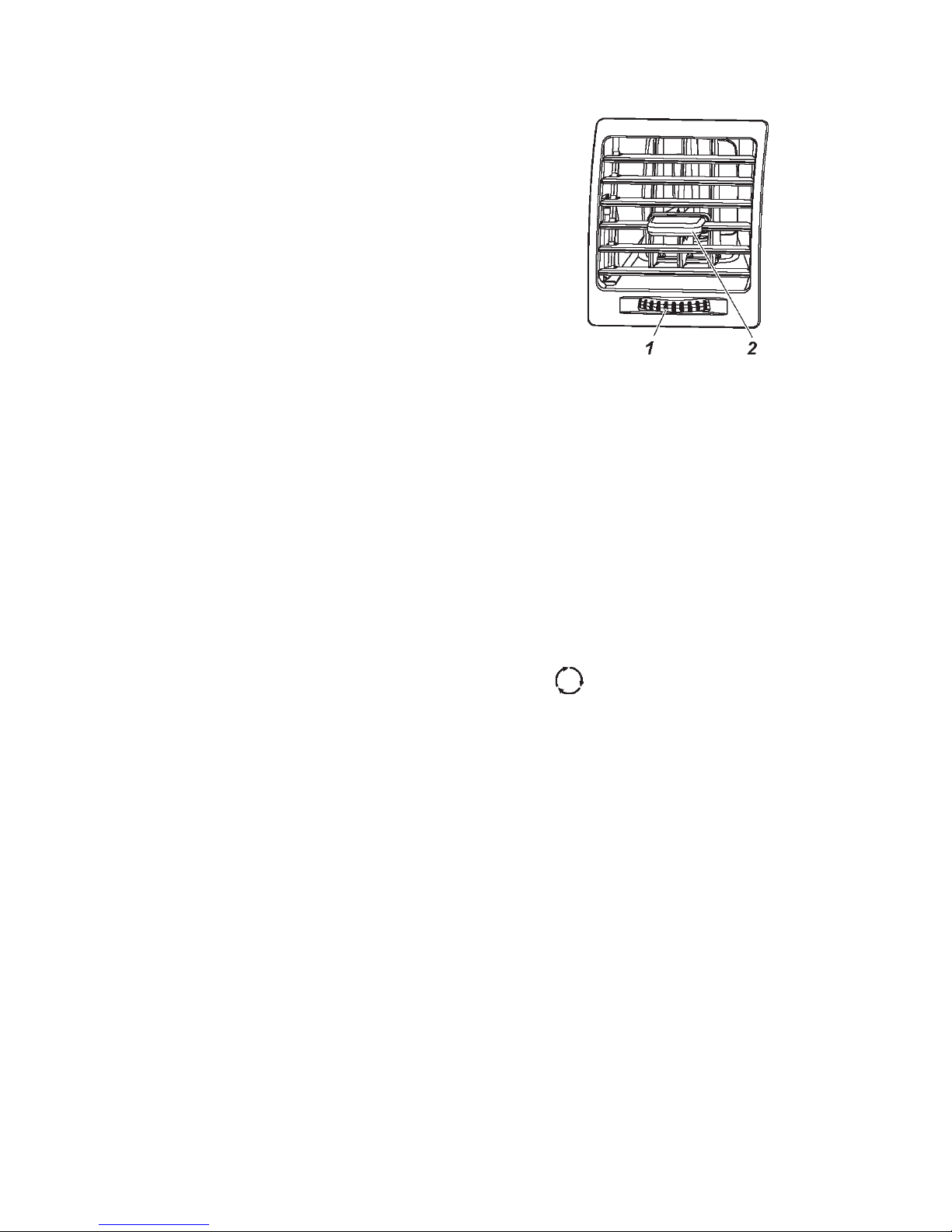
65
WARNING! Low air cooling of the windscreen is allowed when
the interior or foot air cooling mode is switched on.
When the interior heater is switched to any air cooling mode, the
presence of small air currents is allowed in directions different from
the selected mode, pictured on handle pictograph 2 (Fig. 3.13.).
Handle 3 (Fig. 3.13) controls the fan speed of the climate
control unit. Current position of the switch is shown by marker
5 on the moving part of the handle.
The switch has nine fixed positions: "Fan is turned off "
(leftmost position), maximum fan rotation speed (rightmost
position) and seven intermediate fixed positions between them.
For accelerating of stationary motor vehicle interior heating,
recirculation mode can be turned on . When in motion,
recirculation mode should be turned off to avoid window fogging.
On motor vehicles with additional interior heater, heating
rate of the rear triple passenger seat can be increased. In order
to do this, turn on the electric motor fan, additional heater
valve with electric drive 13 (Fig. 3.14) using the switch 5 (Fig.
3.7) positioned at the rear panel of the floor container.
Direction of air currents is adjusted by two deflectors.
Heating and ventilation system is equipped with an air-intake
filter. The filter should be changed after 15000 km mileage or
once per year, depending on what comes first.
Access to the filtering element is provided below the dashboard,
at the feet of the front passenger.
Changing of filtering element 5 (Fig. 3.15) should be performed
as follows:
- force latches 4 away from cover and remove cover 3;
- replace filtering element 5;
- lock filter cover 3.
Fig. 3.13. Deflector:
1 — flap control lever; 2 — air currents
control lever
Page 66
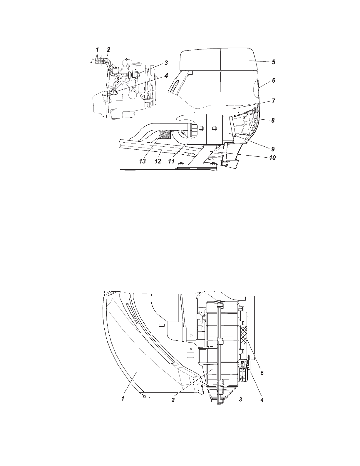
66
WARNING! Using the operation modes of the heater fan from
above average to maximum output rate in pouring rain conditions
can result in soaking of the air-intake filter and ingression of
moisture at the feet of the front passenger.
Fig. 3.14. Additional heater:
1 — heater tubes; 2 — a hose for supplying the cooling fluid to the heater; 3 —
electric motor with a pump (for ZMZ-40905 engine); 4 — fitting; 5 — lid of
the compartment in the floor tunnel lining; 6 — switch unit (Fig. 3.7); 7 — case
of the tunnel lining glove compartment; 8 — deflector (control elements on Fig.
3.13); 9 — deflector sealing; 10 — support; 11 — enclosed radiator and electric
fan of the additional heater; 12+ — air conduit for heating the rear passenger
feet space; 13 — valve with electric drive.
Fig. 3.15. Fan:
1 — dashboard; 2 — fan; 3 — fan cover; 4 — cover latches; 5 — filtering element
Oset
Page 67

67
Interior ventilation
Blowing ventilation of the interior is performed via the same
channels, when the handle 1 (Fig. 3.12) is arranged at maximum
counter clockwise position. Drawing ventilation is performed
via air holes in the rear roof liner and inner panel of the tail
gate apertures, via ventilation grille with valves and rolled down
door window.
Control panel operation mode (Fig. 3.12)
"Manual" operation mode is the main mode of the control
panel.
When this mode is switched on, the control panel scans the
condition of the control elements (rotary switches 1, 2 and 3)
and, depending on their positions, works in accordance with the
prescribed operation algorithm, determines the condition of the
recirculation flap, A/C switch, position of the rotary switches.
In accordance with this data, the control panel generates and
transmits control signals for:
- speed control unit of the heater fan;
- switching the air conditioner on/off;
- motoreducer of the recirculation flap;
- motoreducer of the air current distribution flap and choke
flap;
Besides its own control elements, the control panel interacts
with a number of external switches, namely: "AUTO" mode
switch, "Intensive windscreen heating" mode switch, recirculation
flap control switch, A/C switch.
"Intensive windscreen heating" mode is turned on by a switch
, transmitting a signal to the control panel. The control
panel generates and transmits the control signals necessary for
switching the heating-and-ventilating unit and climate control
unit into this mode to the actuating elements.
In this mode, the control panel changes the position of the
air distribution flap to "To the window" position, air damper to
position, which corresponds to the 8th switch position 1 (Fig.
3.12). However, rotation speed of the climate control unit fan
corresponds with 8th positions of the switch 3. In this mode,
the control panel does not react to changes in positions of the
rotary switches.
Page 68

68
If the control panel in "Intensive windscreen heating" mode
receives a signal to switch on a conditioner, then the conditioner
will be switched on and the system will perform the drying of
the climate control unit.
"AUTO" mode is turned on by switch " "
In this mode, the control panel controls the air damper so
that it is set by the rotary switch 1 (Fig. 3.12), temperature
is automatically maintained if the fan rotation speed of the
climate control unit is manually set (by rotary switch 3) and
the distribution of the air currents is manually operated (rotary
switch 2).
The air temperature automatically maintained in the motor
vehicle interior can vary from +16 to +28°C. Moreover, the
values indicated in the table 3.1 are also available.
If "AUTO" mode is switched on and the position of rotary
switch 1 is changed, then the interior air temperature is set in
accordance with the new value.
Switching off "AUTO" mode occurs after pressing the
"AUTO" switch a second time or after switching on the "Intensive
windscreen heating" mode.
Position of
switch 1
1 2 3 4 5 6 7 8 9
Temperature,
16 18 20 21 22 23 24 26 28
°C(±2°C)
Table 3.1.
"Interior preheating"+ mode.
The control panel goes to "Interior preheating" mode if the
source of power is the liquid heater.
When this mode is turned on (the ignition is turned off),
the control board indicates this mode with orange blinking
illumination on rotary switch 2 with a 4.5 second blinking
period (1.5 seconds turned on/ 3 seconds turned off).
If the position of rotary switch 3 exceeds position 4 of the
switch, then the control panel limits the maximum rotation
speed of the fan and rotary switch 3 goes to the 4th position in
order to prevent forced accumulator battery discharge.
Page 69

69
If rotary switch 3 is turned to "OFF" position, then the rotary
speed of the fan corresponds to position 2 of rotary switch 3 (i.
e. fan is rotating at minimum speed).
When the "Preheating interior" mode is turning on, the heater
flaps go to the following positions:
- air current distribution flaps to "At the feet" position;
- recirculation flap to "Opened" position (air induction from
the motor vehicle interior);
- choke flap to "Maximum opened" position (maximum air
temperature).
After 5 minutes in the above described positions, the control
panel changes the positions of the flaps to "Ventilation of the
interior and at the feet" position. The control panel remains in
the current operation mode with current flap positions until the
liquid pre-start heater is turned off or ignition is turned on.
If the ignition is turned on before the liquid pre-start heater
is turned off, then the control panel automatically goes to
"Manual" operation mode and the actuating elements of the
climate control unit are adjusted in accordance with the control
elements of the climate control unit.
Air conditioner
Depending on the configuration, the motor vehicle can be
equipped with "Sanden" air conditioner.
The air conditioner is switched on by a button .
The control panel switches on the air conditioner if the air
temperature at the evaporator output is above or equal to 7°C. If
the air conditioner is operating and the air temperature decreases
to 4°C or lower, then it turns off regardless of the A/C switch
position.
If an additional electric pump of the heater is turn on and the
control panel receives a signal to switch on the air conditioner,
then the control panel should simultaneously turn on the air
conditioner and turn off the additional electric pump of the
heater.
If the A/C switch transmits a signal to turn off the air
conditioner, then the control panel turns on electric pump of
the additional heater, if switch handle 1 is in "ON" position.
When the control panel receives the signal from the A/C switch
to turn off the air conditioner, the control panel turns it off.
Page 70

70
Recirculation mode can be activated with a button for
more effective cooling (air induction from the motor vehicle
interior).
Warning. Prolonged usage of the recirculation mode can
cause window fogging and stuffy air in the interior.
WARNING! Turn on the air conditioner even during cold seasons
at least one to two times per month for 5-10 minutes. It provides
the required compressor lubrication and extends the service life of
the system.
WARNING! In order to prevent the engine from overheating,
when the air conditioner continuously works at idle engine run and
when moving in severe conditions with the engine load near to full,
the air conditioner compressor can often be shut off together with
a loss of cooling efficiency. In order to improve the air conditioner
efficiency in the given conditions, it is recommended that the rotation
speed of the climate control unit fan be raised at the flick of switch
3 (Fig. 3.12) and a minimum air temperature be set at the flick of
switch 1.
Lighting lamps
Interior lighting is performed by pilot lamps 3 (Fig. 3.16)
and rear interior light 4.
The pilot lamps unit includes sections of individual interior
lighting. Left and right sections of individual lighting switches on
by pressing the corresponding left 1 (Fig. 3.17) or right 3 switch.
Operation mode of the interior ambient lighting depends on
switch 2 position:
— the lamp switches on and off automatically, when
opening or closing the door. The interior lamp is on if any of
the motor vehicle doors are open. After closing all the doors,
the lamp lights for 25 seconds (depending on the configuration),
and then smoothly goes off for 2 seconds.
— the lamp is on until it is switched off.
When switch 2 is in mid-position, the lamp switches off.
Lamp of the luggage compartment turns on (Fig. 9.53) when
opening the tail gate.
The control of the interior lighting units ("polite" light) with
a smooth change of brightness for 2 seconds when turning on
and off the interior lighting lamps is enabled:
- when opening any of the side doors;
Page 71

71
- when turning on and off the "Security" mode via a radio
channel of the remote control panel;
- when receiving "Find motor vehicle in unlighted parking
area" command via remote control panel;
- when turning on the ignition, after all the doors are closed
while the lamp is still in "on" position;
- 25 seconds after all the side doors are closed, if during this
period the ignition wasn't turned on, any of the side doors were
not open, the "Security" mode was not switched on via a radio
channel of the remote control panel;
- in 10 minutes when one or more side doors are constantly
open (if during this period all the side doors were not closed, the
tail gate was not opened or closed, the ignition was not turned
on).
The lighting turns on when the ignition is turned off and the
doors are open, and also for not more than 25 seconds after all
the doors are closed.
When the ignition is turned on, the interior lighting is on
only if at least one side door is open.
Interior rearview mirror (Fig. 3.16)
Interior mirror is adjusted by pivoting around its joint.
WARNING! In order to avoid blinding by headlights of vehicles
traveling behind during night driving conditions, it is necessary to
change the tilt angle of the mirror with a lever positioned below the
mirror.
Exterior rearview mirrors
Selection of the best position for the exterior mirror is
performed with switch 9 (Fig. 3.9). Rearview mirror heating is
activated by switch or , positioned on the dashboard.
In order to reduce the motor vehicle size when parking in
tight space, it is necessary to fold in the exterior rearview mirrors
to the side doors of the motor vehicle by pressing them toward
the rear part of the motor vehicle.
Sun visors (Fig. 3.16)
In case of necessity it is recommended that the sun visors be
positioned in either of the two positions: flip the sun visor into
its downward position or flip it down and turn toward the side
door.
Page 72
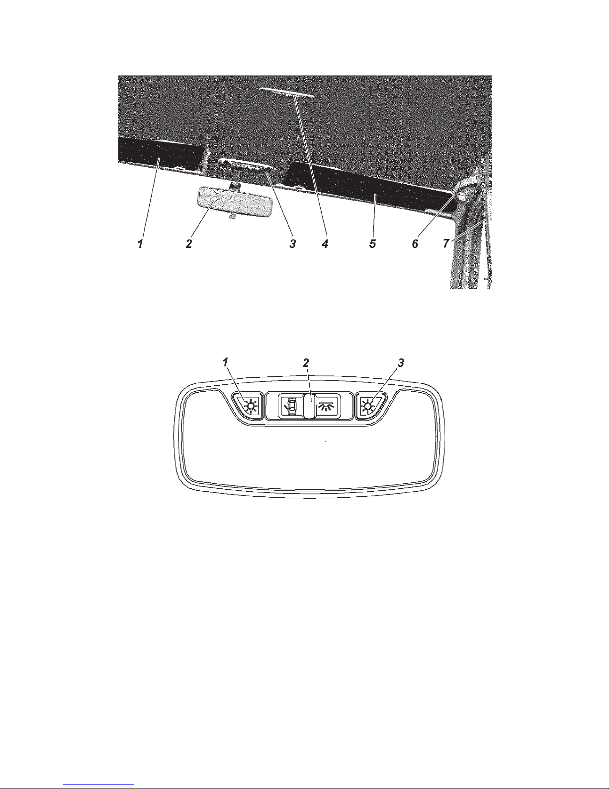
72
Doors
WARNING! Before opening a door, make sure it will not be a
hindrance for other road users.
Before closing a door, make sure it will not catch someone or
something.
Driver's door is locked with a key from outside. If it isn't
locked, the door opens when pulling moving part 2 (Fig. 3.18,
3.19) of the door handle.
The door opens from inside when turning handle 2
(Fig. 3.20,3.21) toward you.
Fig. 3.16. Lighting lamps, interior rearview mirror, sun visors and hand grip:
1,5 — sun visors; 2 — interior rearview mirror; 3 — a unit of pilot lamps;
4 — rear interior lighting lamp; 6 — hand grip; 7 — seat belt height adjuster
Fig. 3.17 Interior space lighting unit:
1 — left section switch; 2 — general lighting mode switch; 3 — right section switch
Page 73
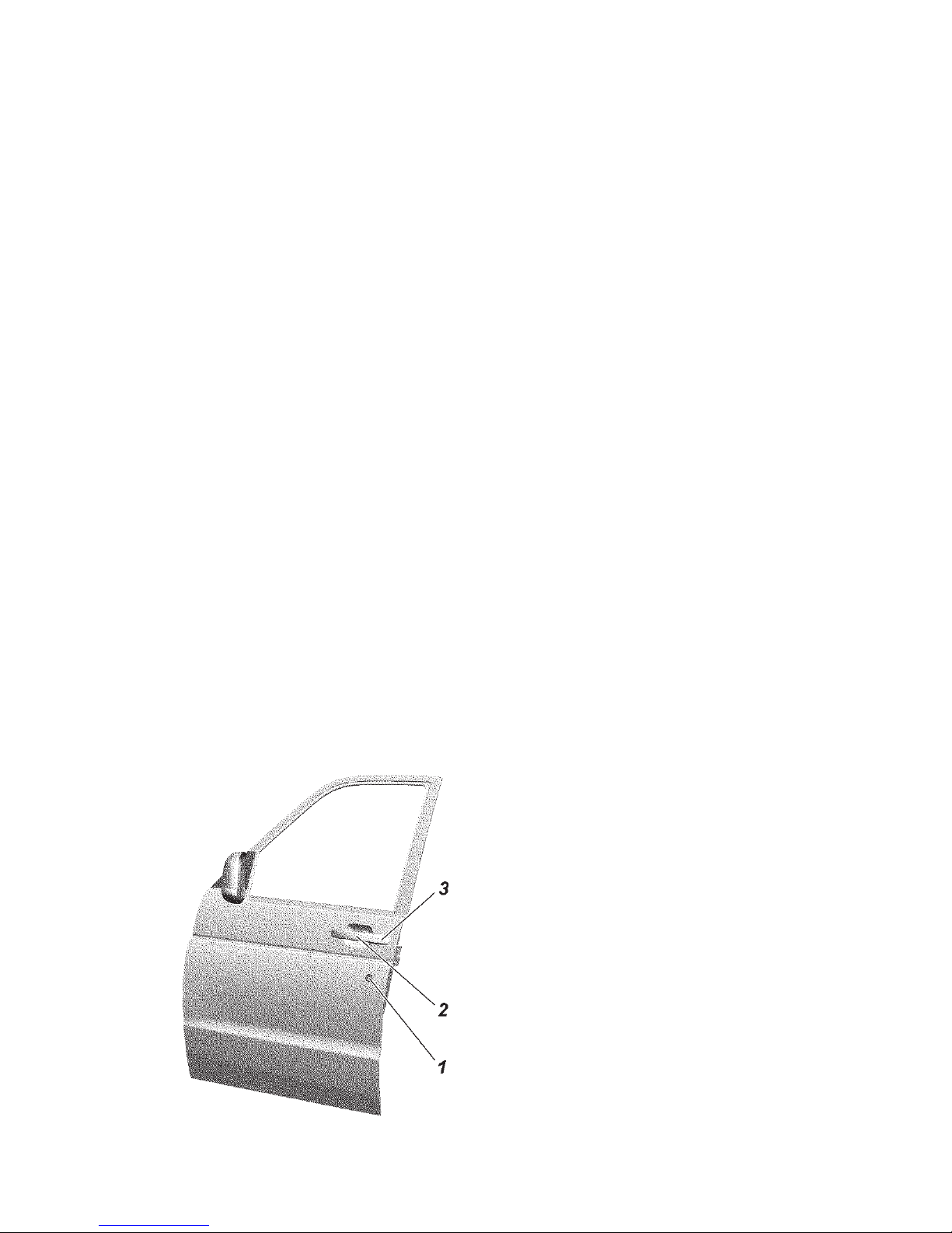
73
The doors are locked by pressing button 1 (Fig. 3.20, 3.21).
The tail gate is not equipped with an inside handle which
opens it or a button which blocks the lock.
The motor vehicle is equipped with an electric blocking system
of the door locks. When locking the front left door with a key,
all the door locks are locked simultaneously. Every door (except
the front left door) can be locked or unlocked individually from
inside the interior by pressing the corresponding door locking
button.
WARNING! When leaving the motor vehicle, do not leave
the door key or ignition key inside it. Passengers inside the motor
vehicle, especially children, could accidentally lock all the doors.
The locks in the rear doors and the tail gate have interior
handle blocking levers ("child lock") which prevent the doors
from opening from inside the motor vehicle. The handle is locked
by turning lever 1 downward (Fig. 3.19), 6 (Fig. 3.21).
The windows of the side doors go up and down by turning
the switches of the power windows 3, 4, 5, 6 (Fig. 3.9 for UAZ
Patriot, UAZ Pickup) or 1, 2 (Fig. 3.22 for UAZ Cargo).
WARNING! When closing the power windows, fingers or other
body parts may be caught, which could lead to serious injury.
Therefore, pay attention when using the power windows, especially
if there are children in the motor vehicle. If there is a child in the
motor vehicle, make sure there are no body parts of the child in the
Fig. 3.18. Front door (view from
outside):
1 — door lock switch; 2 — movable
part of the door handle; 3 — door
handle body
Page 74
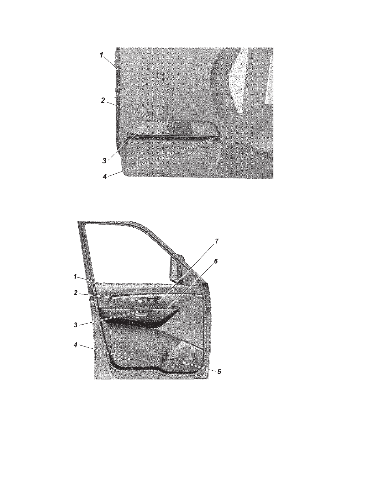
74
Fig. 3.19 Tail gate (view from outside):
1 — lever for blocking a door interior handle;2 — door handle; 3 — pad
housing of license plate lamp 4 + — rear view camera
Fig. 3.20. Front door (view
from the interior):
1 — locking button; 2 — door
handle; 3 — armrest handle;
4 — pocket; 5 — place for loudspeaker mounting; 6 — switch
unit (Fig. 3.9, 3.23); 7 + — place
for twitter mounting
window aperture when opening/closing the window. If a body part it
caught, it is necessary to stop closing the window immediately and
start to open it. When there are children in the motor vehicle, it is
recommended that the power windows be turned off using switch 1
(Fig. 3.9).
Page 75
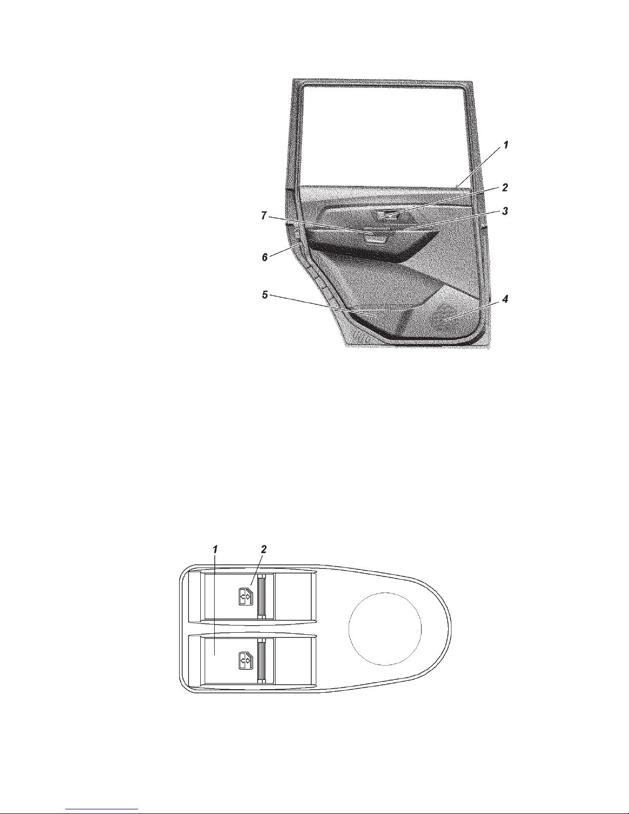
75
Fig. 3.21. Rear door (view
from the interior):
1 — locking button; 2 — door
handle 3 — power window
control switch; 4 — place
for loud-speaker mounting;
5 — pocket; 6 — lever for
locking door interior handle;
7 — armrest handle
The driver bears full responsibility for inappropriate usage of
the power windows. The driver should inform the passengers about
the directions of use and dangers when the power windows are used
inappropriately.
Keep children away from the switches of the power windows! Do
not hang hands or other body parts out of the open window, keep
children from doing this.
When leaving the motor vehicle, it is necessary to take out the
ignition key in order to turn off the power windows and prevent the
Fig. 3.22. Driver switch pack:
1 — window control switch of the right front door; 2 — window control switch
of the driver's door
Page 76

76
passengers left in the motor vehicle from getting injured accidentally.
If the key was left inside the motor vehicle, the system warns the
driver about it by making the immobilizer buzzer produce beeping
sounds when the driver's door is open. Never close the motor vehicle
from outside if there are passengers inside it — it will not be possible
to open the windows from inside the motor vehicle.
When closing/opening the windows, keep in mind the safety
requirements.
Successful performance of the power windows depends on the
cleanliness of the windows.
Seats
WARNING! Do not adjust the driver's seat when the motor
vehicle is moving.
The driver's seat and tilt angle of the steering column should be
adjusted so as to provide the necessary position of the driver: the
driver should tightly bear against the back rest of the seat; elbow
joints of both arms should be slightly bent when holding the upper
part of the steering wheel; the legs should not be extended at full
length when pressing the pedal as far as it can go.
The seat headrests should be adjusted so that the back of the
head touches the midpoint of the headrest when the head rests
upon it. If it is not possible, then the headrest should be raised
to the uppermost position for very tall persons and lowered to the
lowermost position for very small persons.
After adjusting the positions of the front seats, it is necessary to
adjust the position of the upper mounting points of the seat belts.
It is forbidden to sit on the knees and load the individual points of
the seat in different ways so as not to damage the heating elements.
Do not use the heating mode if the seats are not occupied by
passengers or there are any items such as a special baby seat,
bag, etc. This may cause a malfunction of the heating elements
of the seat heating system. It is recommended that the switches of
the heating system be turned on only when the engine is started. It
significantly saves the accumulator battery capacity.
If the voltage drops in the electrical on-board system of the motor
vehicle, the seat heating is automatically switched off to provide
sufficient power for the engine control system.
If you or a passenger suffer from low pain or temperature
threshold, e.g. as a result of drug treatment, paralysis or chronic
Page 77
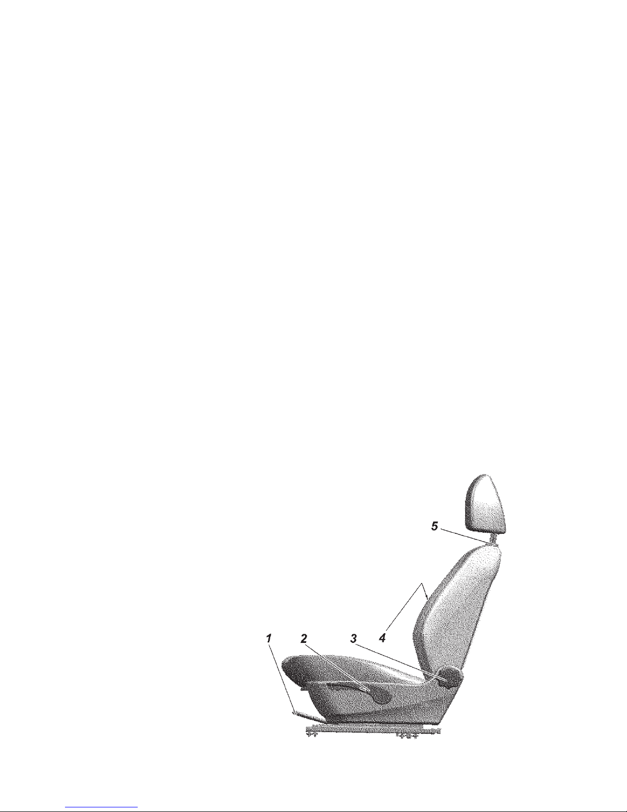
77
disease, it is recommended that you do not use the heater. It may
result in burns on the back, buttocks and legs. If you still want to
use the seat heating, it is recommend that you turn on the heating
for short periods of time.
Do not use additional pillows between the seat and the passenger
or the driver.
It is forbidden to place foreign objects under the driver's seat
and in the area of his feet.
Changing of the headrest height or its removal is performed
by moving the headrest in a vertical direction:
- up — by arm force (to the uppermost position);
- down — when the button of the headrest lock is switched on.
Removal is performed by moving the headrest upward from
the uppermost position while pressing the button of the headrest
lock.
Adjustment of the front seats in the longitudinal direction is
performed by lever 1 (Fig. 3.23): Pull the lever located under
the seat cushion which blocks the longitudinal movement of
the seat and move the seat to the desired position. When the
adjustment is finished, release the lever and make sure that the
seat is securely fixed by moving it back and forth when the lever
is released. Backrest angle is controlled (step-less adjustment)
by turning handle 3 at the base of the backrest.
Fig. 3.23. Front seat:
1 — a catch for locking lateral movement of the seat;
2 + - a handle for adjusting the height of the driver
seat airbag; 3 — a handle for adjusting the tilt of the
seat squab; 4 — a handle for adjusting lumber support
of driver seat airbag; 5 — headrest lock button
Page 78
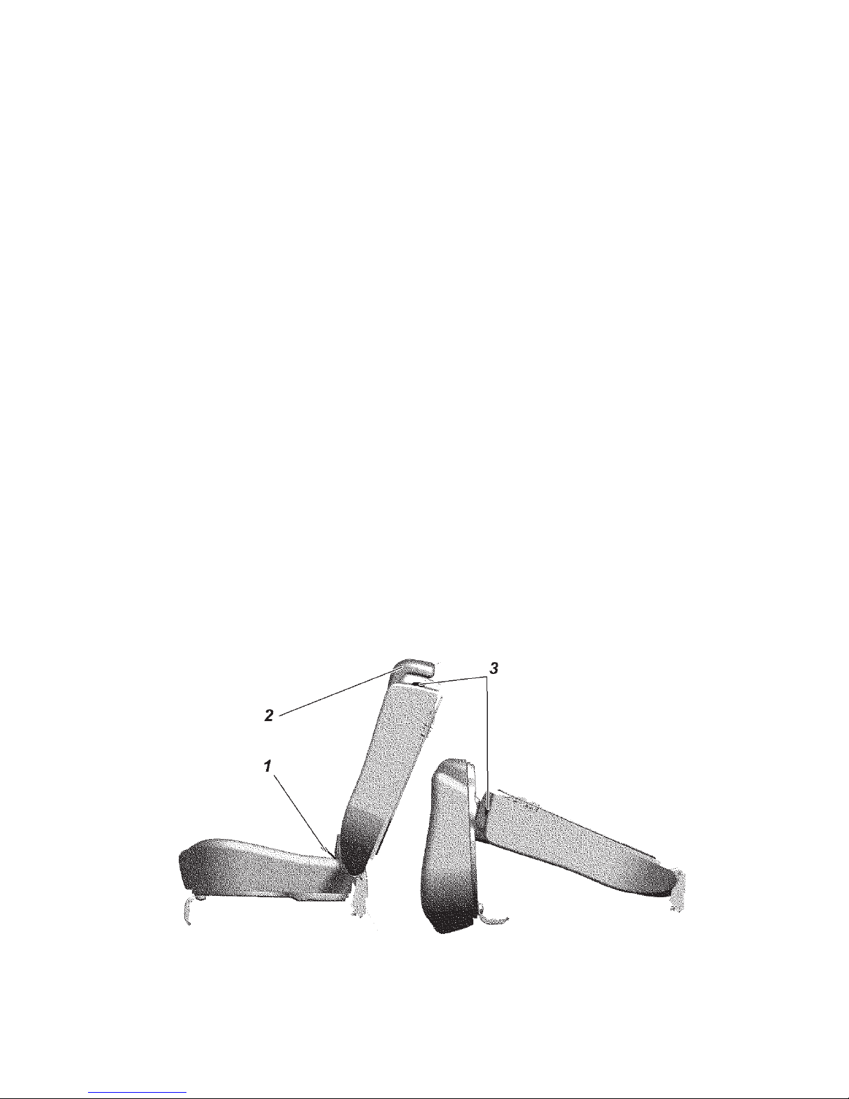
78
For your convenience, make the adjustments with the door
open.
The driver's seat in some motor vehicle configurations is
equipped with a lumbar support mechanism and seat height
adjustment.
Lever 4 for adjustment of the lumbar support is located on the
inner side surface of the backrest. Turning the lever forward or
backward results in a corresponding change of the convex section
in the lower part of the seat backrest, providing comfortable
support for the lumbar part of the spine.
In order to raise the driver's seat, pull up handle 2 several
times until it is set to the desired height. To lower the driver's
seat, pull down handle 2 several times until it is set to the desired
height.
For your convenience, make the adjustments with the door
open.
Rear triple seat (Fig. 3.24) consists of pillows and backrests
for one and two passengers.
In order to increase the space of the luggage compartment,
the rear seat can be folded down and every part of the seat can
be unfolded separately. Unfolding of the rear seat is performed
as follows:
- pull the loop 1 (Fig. 3.24) and set the pillow to the upright
positions;
Fig. 3.24. Rear three-seater seat:
1 — releasing and raising loop of the rear seat cushion; 2 — seat
squab headrest 3 — rear seat squab release lever
Page 79

79
- remove headrest 2;
- pull lever 3 in the direction of movement of the motor
vehicle, release and fold the backrest as shown in the diagram,
Fig. 3.24;
- to return the backrest to its initial position, raise the backrest
until the headrest lock is activated;
- to return the pillow to its initial position, turn it back to the
horizontal position (for UAZ Pickup until the lock is activated);
- mount the headrests.
Change the position of the rear seat with the rear doors open.
WARNING! When returning the seat to its initial position, make
sure that it is securely fixed to avoid the folding of the seat during
the movement of the motor vehicle.
WARNING! When folding the two-seat section of the rear triple
seat, make sure the center seat belt is not fastened.
WARNING! Mounting of the "universal" child restraint system,
according with the Table 3.2, is performed with the seat belts of
the vehicle. Children under 1.5 years of age should sit in the child
restraint device only facing backwards.
WARNING! Installation of the ISOFIX child restraint system
should be carried out in accordance with the table 3.3 — "Mounting
points for the ISOFIX child restraint system on the motor vehicle".
Table 3.2.
Seats
Weight
group
Front seat
passenger's
Rear
side seat
Rear
middle seat
0–10 kg (0–9 months) X* U* X
0+ — 13 kg (0–2 years) X U X
I — 9–18 kg
(9 months–4 years)
U U X
II and III — 15–36 kg
(4–12 years)
U U X
* Child seat category
U — universal category of a child seat suitable for settling a child
both into a front-facing seat and a rear-facing seat.
X — child seats mounting is not permitted.
Page 80

80
Position of ISOFIX in
Weight Dimension class Clamping vehicle
category device
Second row
left right
F (Transverse cradle) ISO/L1 IL X
0 — up to 10 kg G (Transverse cradle) ISO/L2 X IL
E (Rear-facing seat) ISO/R1 IL IL
E (Rear-facing seat) ISO/R1 IL IL
0+ — up to 13 kg D (Rear-facing seat) ISO/R2 IL IL
C (Rear-facing seat) ISO/R3 IL IL
D (Rear-facing seat) ISO/R2 IL IL
C (Rear-facing seat) ISO/R3 IL IL
I — 9–18 kg B (Front-facing seat) ISO/F2 IUF IUF
B1 (Front-facing seat) ISO/F2X IUF IUF
A (Front-facing seat) ISO/F3 IUF IUF
IUF — a place suitable for setting a front facing child seat which is "universal" for the given category of
child seats with ISOFIX fasteners;
IL — a place suitable for setting a "universal" child seat with ISOFIX fasteners;
X — position SOFIX not suitable for child seat systems ISOFIX.
Table 3.3
Page 81

81
Seat belts
REMEMBER! Seat belts are an efficient means of protection
of the driver and the passengers against the drastic consequences
of road traffic accidents. The use of seat belts is required!
WARNING! The seat belts must be replaced if they have been
worn or damaged and after a critical load as a result of a traffic
accident.
Replacement of the seat belts must be performed only in the
authorized service shops of UAZ PJSC (addresses of the authorized
service shops are listed in the service book).
Seat belts are designed for individual use by drivers and adults
taller than 144 cm and weighing at least 36 kg.
All motor vehicle seats are equipped with three-point seat
belts (Fig. 3.25) with retraction mechanisms. To fasten the seat
belt, pull belt tongue 3 without twisting the straps and insert it
into lock 4 until it clicks. Press the red button of the lock to
unfasten the belt.
The center seat belt of the UAZ Pickup is a static lap belt.
The seat belt height adjuster has three fixed positions.
The position of the upper mounting point of the seat belt is
adjusted by moving belt guide support 2 up or down. To do it,
pull on the support when pressing the decorative screw cap with
your thumb and then move the guide support. Also, in order to
increase the height, pulling up the guide support is enough.
Keep the belt straps and buckles clean. If they become dirty,
clean them with an alkali-free soap solution.
Protect the straps from touching sharp edges.
Protection from direct sunlight is recommended.
In order to clean the straps from dust, blow with compressed
air not less than once per year.
It is forbidden to:
- twist the straps, fold them lengthwise and allow excessive
slack;
- iron the straps;
- strap in a child sitting on the lap of a passenger;
- make changes in the belt design.
Page 82
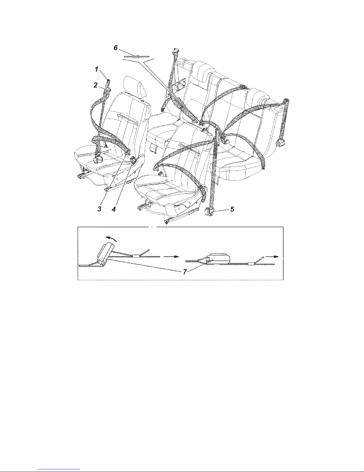
82
WARNING! When the motor vehicle moves, the seat backrest
angle should be minimal, but sufficient for the convenience of the
driver and passengers. The seat belts are more effective when the
driver and passengers sit up straight, resting on the backrest. If the
seat backrest is inclined too much, the seat belt may slip, increasing
the risk of getting injured in an accident.
WARNING! Control the condition of plastic restriction clip 6
(Fig. 3.25) of the center seat belt.
Fig. 3.25. Seat belts:
1 — seat belt height adjuster; 2 — seat belt guide bracket; 3 — lock catch; 4 —
lock; 5 — inertia reel; 6 — clip; 7 — adjuster for static middle belt (UAZ Pickup)
Sling shortening
Sling elongation
Pull Pull
Page 83
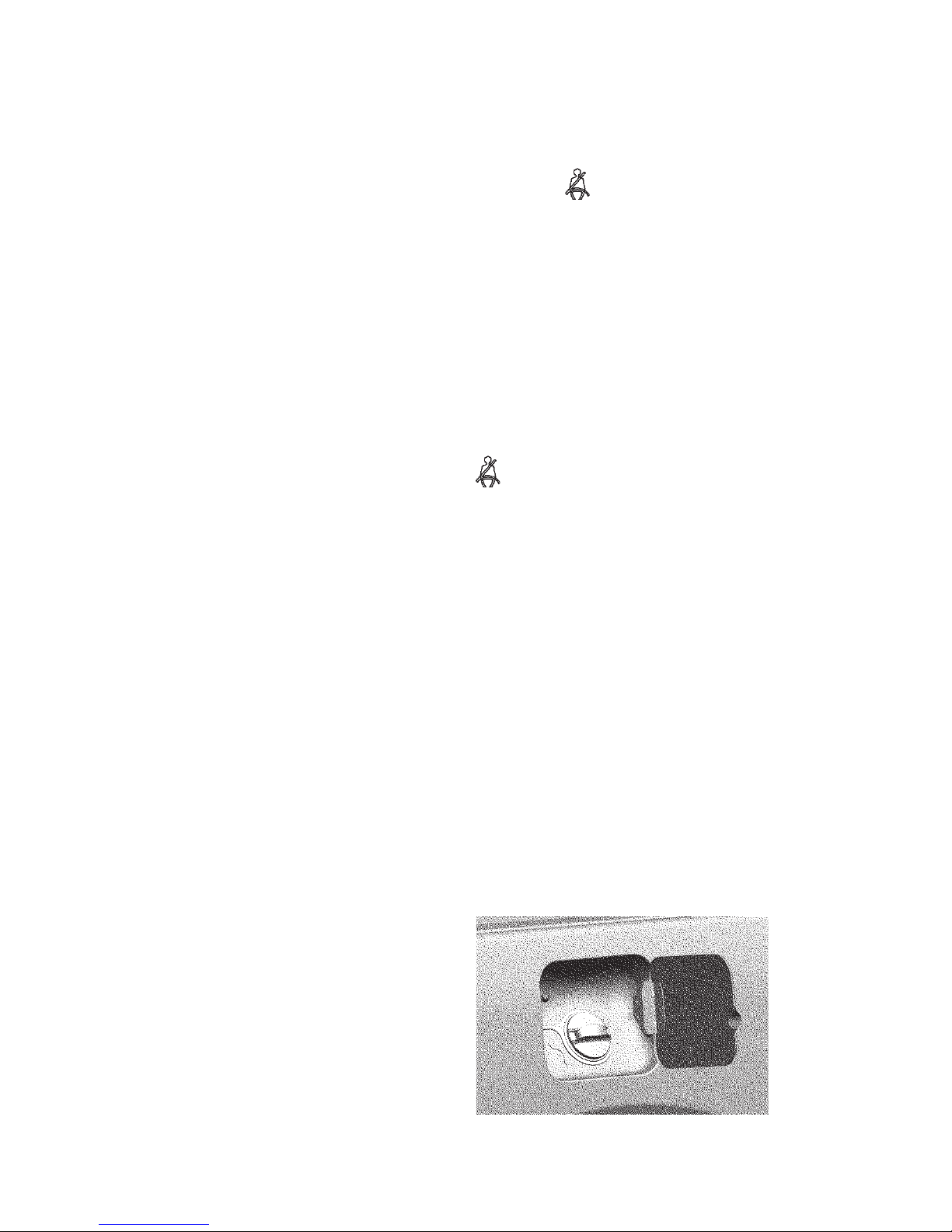
83
Unfastened seat belt signal device.
If the seat belt of the driver is not fastened when the ignition
is turned on, the seat belt signal device
on the instrument
cluster turns on. The signal device turns off when the ignition
is turned off or the strap is inserted to the retractable seat belt.
If the motor vehicle moves more than 60 seconds or 500
meters or reaches a speed of 25 km/h and the seat belt of the
driver is not fastened, an additional horn turns on.
When the motor vehicle moves and the seat belt of the driver
isn't fastened within 30 seconds, the warning horn turns off.
After the motor vehicle stops and then starts again, the audio
alarm algorithm will repeat if the driver's seat belt is not fastened.
Diagnostics of defective unfastened seat belt indicator.
Seat belt signal device is on
when the driver's seat belt is
fastened. Disconnect the receptacle of the retractable seat belt
buckle:
- the signal device goes off if the retractable seat belt buckle
is defective;
- the signal device remains illuminated if the wiring harness
or the instrument cluster is defective.
Fuel tank plug
Open the fuel filler door (Fig. 3.26) to access the fuel tank
plug.
WARNING! Fuel tank hatch cover has an opening angle
restriction of 70°. Opening the cover to a larger angle will cause a
deformation of the hinge movable link and when closing the cover
of the fuel filler door the hinge will not butt up against the door
bumper.
Fig. 3.26. Fuel filler flap and choke
plug
Page 84
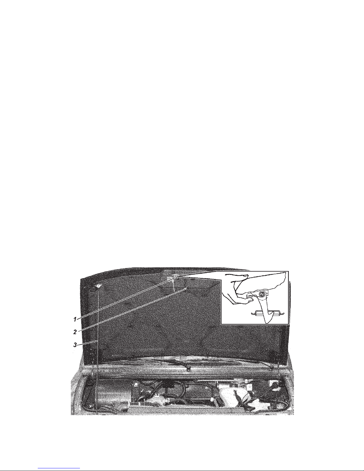
84
Hood
In order to open the hood, pull lever 21 (see Fig. 3.1, 3.2)
between the hood and the radiator lining, push the clamp of
hook 1 (Fig. 3.27) and lift the hood. Take out bonnet stay 3
from holder 2 by pushing it and insert it into a special opening
above the right head light. Depending on the configuration, the
motor vehicle may be equipped with air springs for the hood
which facilitate lifting of the hood and keep it open.
The hood closing must be performed from a height not more
than 200 mm above the radiator lining. If the motor vehicle is
equipped with air springs for the hood, the latter should close
by inertia after overcoming the force of the air springs.
WARNING! Before closing the hood, make sure it will not
entrap anything and the bonnet stay is securely fixed in the holder.
When closing the hood, check that the lock works properly.
Avoid free falling of the hood from a large opening angle.
Wind-screen wipers, water pumps for the washer
To ease washing the windshield manually, wiper blades must
be placed in fixed position away from the windshield.
In cold seasons, before switching on the windshield wipers,
make sure the wiper blades are not frozen to the windshield.
Fig. 3.27. Hood: 1 — locking hook; 2 — support; 3 — rest
Page 85

85
Windshield wipers should not be turned on when the windshield
is dry. Keep the wiper blade rubber out of contact with fuel and
oil.
While operating, make sure the windshield wipers work
properly and their parts are securely fixed. Periodically clean
the windshield and rubber edges of the wiper blades from dirt
and oil.
During seasonal service, keep the windshield wipers on for
15-20 minutes. Wiper blades must be placed in fixed position
away from the windshield. The wiper blade arm of the rear
window must be detached.
After 18-24 months of operation replace wiper blades or their
rubber edges if necessary.
Replacement of wiper blades of windshield wipers
To replace wiper blades of windshield wipers perform the
following steps:
- lift the arm of the windshield wiper from the windshield or
the rear window;
- rotate the wiper blade about its axis of rotation and place
it nearly perpendicularly to the lever; prior to this step release
the wiper blade lock by pressing the tab on the adapter between
the wiper blade and the lever; dismount the wiper blade from
the lever.
A new wiper blade is installed in the reverse order.
NOTE: Installation of frameless wiper blades is possible.
Washer reservoir 2 (Fig. 3.28) is filled with clean water (in
summer) or a special nonfreezing fluid (in winter).
To drain water from the washer reservoir pull out the washer
reservoir and disconnect electric wiring and tubes from the
washer.
Adjust the direction of water stream by changing the position
of spraying nozzle balls with a needle inserted into the ball
channel (feed hole).
When the spraying nozzle is clogged, disconnect the tube
and air blow the spraying nozzle.
To avoid failure of the washer pumps check the water level in
the reservoir; 20 mm from the bottom is the lowest level permitted.
Do not keep washer reservoirs turned ON for more than 10
sec.
Page 86
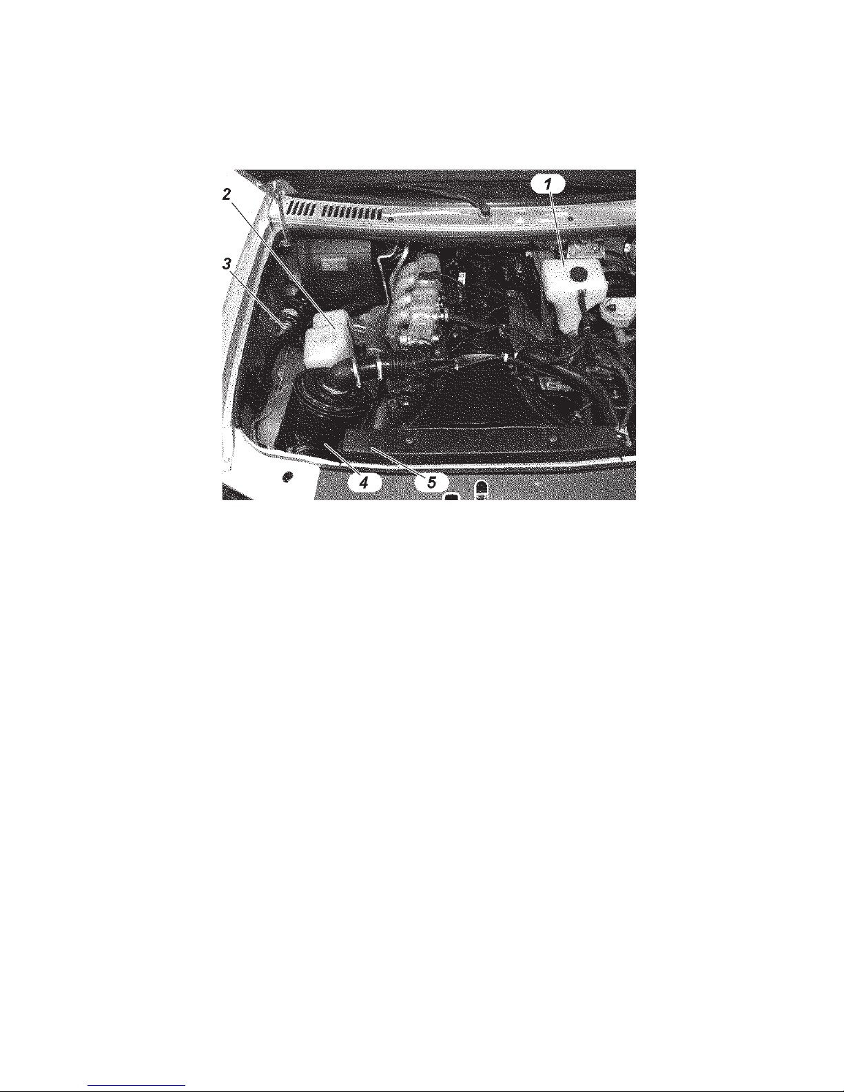
86
WARNING! When switching on the washer of the tail gate
door, there may be water feed delay up to 2,5 sec.
Fig. 3.28. Underhood space (fragment):
1 — expansion tank of the engine cooling system; 2 — washer reservoir; 3 —
auxiliary electric heater pump; 4 — air filter; 5 — engine cooling system radiator
Luggage compartment
Luggage compartment has a pullout cover to protect the
luggage.
WARNING! Avoid placing objects on the cover.
WARNING! No passengers are allowed in the luggage
compartment during driving.
WARNING! Tail gate door only opens from the outside.
Page 87

87
Chapter 4. MOTOR VEHICLE PREPARATION UPON
RECEIPT FROM THE MANUFACTURER
Dealers must sell the motor vehicle only after pre-purchase
preparations, specified in the service book.
If the motor vehicle was delivered to the sales point and
traveled more than 100 kilometers (OST 37.001.082-82), all the
preliminary preparations for ferrying must be carried out as a
part of the pre-purchase preparations.
Chapter 5. MOTOR VEHICLE RUNNING-IN
Long-term and fail-safe service life of the motor vehicle
depends to a greater extent on the run-in of the parts during
the initial service period.
The running-in kilometrage equals to 2500 km.
During the running-in period, observe the following rules:
1. Crankshaft rpm of engine must not exceed the 3/4 of the
nominal rotational speed.
2. Do not exceed the motor vehicle nominal load.
3. Do not drive along the tough roads (deep mud, sand, steep
inclines, etc.).
4. Do not haul the trailer.
5. Do not change the oils filled in the engine and units at
the manufacturing plant.
6. Check and adjust the tension of the auxiliary unit drive
belts if necessary, as they reach the maximum stretch during the
running-in period.
7. Check the temperature of brake drums and discs and in
case of raising the temperature, adjust the parking brake actuator
or brake pedal free play.
8. Check the temperature of wheel hubs and in case of raising
the temperature, loosen the tightness of bearing.
9. Check condition of all attachments and connections of
pipes; eliminate leakages of oils, fuel, coolant and hydraulic
fluid, if you find it.
10. The scope and period of the motor vehicle maintenance
are specified in the service book.
Page 88

88
Chapter 6. STARTING AND SHUTTING DOWN
THE ENGINE
GENERAL REQUIREMENTS
WARNING! It is strictly forbidden to start and warm up the engine
indoors without good ventilation in order to avoid carbon monoxide
poisoning.
It is forbidden to start the gasoline engine with improperly
installed high-voltage wires from the ignition coils to the spark
plugs or low-voltage wires to the ignition coils. It can cause failure
of the flywheel ring gear teeth and destruction of the starter.
For reliable start of the engine, viscosity grade of the engine oil
should correspond to the operating temperature range of the motor
vehicle
Before starting the engine, check for the coolant in the engine
cooling system, fuel, oil level in the engine crankcase and power
steering tank.
Shift the gearshift lever in neutral position.
Remember that (in order to prevent the starter from
accidentally switching on when the engine starts) the ignition
switch is equipped with the interlock, which allows the engine
to be restarted only when the key returns to "0" position (Fig.
3.4).
Switch on the starter for a maximum of 5 seconds. As soon
as the engine starts, immediately release the ignition key, it will
automatically return to "I" position. Warm up the engine.
It is forbidden to increase a crankshaft speed for acceleration
of the engine warming-up process.
Do not drive a motor vehicle with a cold engine.
The temperature of coolant must be not less than 60°C for
the warmed up engine of ZMZ-40906 family.
ZMZ-40906 ENGINE STARTING
Starting a cold engine at -20°C and above*
1. Turn on the ignition. It should activate the electric fuel
pump, which can be heard when the engine turned off.
2. If the engine turns on after prolonged stop, it is recommended
to wait until the electric fuel pump is switched off (about 5
seconds).
Page 89

89
3. The system functions correctly if a malfunction indicator
lamp (on the instrument cluster) switches on and off. If the
malfunction indicator lamp continues to glow, it is required to
detect and remove the malfunction (refer to "Diagnostics").
WARNING! If the motor vehicle has malfunctioning systems
(the malfunction indicator lamp continuously glows), it can cause
the failure of the engine converter and oxygen sensor in exhaust
gases.
4. Press the clutch pedal as far as it can go.
5. Switch on the starter.
6. Release the key after starting the engine (turn off the
starter).
Try to start the engine not earlier than 15 — 20 seconds after
the first attempt.
When starting the engine, it is not recommended to press
the throttle pedal.
After starting the engine, its system will automatically set the
fast idle speed to warm up the engine and gradually reduce it as
the engine warms up.
If the engine does not start after the third attempt, stop the
ignition, detect and remove the malfunction.
Starting a cold engine at temperature below -20°C.*
In order to ease the starting of cold engine at low temperature,
preliminary warm up is required (by steam, hot air, etc.).
The following sequence of operations is the same as in case
of starting from cold at -20°C and above.
Starting a hot engine
The sequence of operations is the same as in case of starting
from cold at -20°C and above.
If the engine does not start after the third attempt, press the
throttle pedal as far as it can go and turn on the starter for 2-3
seconds. The control unit will perform "Scavenging of the engine
cylinders mode" function and then retry to start the engine.
Shutting down the engine
In order to shut down the engine, turn the ignition key to
the "0" position. Before shutting down the engine, let it run for
1-2 minutes at low crankshaft speed.
*If the motor vehicle is equipped with the starting pre-heater, it is recommended to use it at -10°C and below
Page 90

90
ZMZ-51432 ENGINE STARTING
Fuel and oil should correspond to the season.
If necessary, release the air from the feed system, as suggested
in the "Engine" section.
Warning! Do not press the throttle pedal during the starting
of the engine!
Do not drive the motor vehicle right after the starting of a cold
engine. After starting the engine, it should operate at minimum
idle speed for 1-2 minutes in order to put the turbocharger and
engine systems into working order. After this procedure, the
engine is ready for service.
Do not overload the engine when starting it cold. The optimal
service conditions of the engine are when the temperature of
the coolant is +60–95°C.
Starting a cold engine
1. Turn on the ignition.
2. If one of the temperature sensors (coolant, air or fuel
sensors) detects a temperature below +10°C, then the heating
plugs indicator starts to glow when turning on the ignition .
The duration of pre-start warming up process with heating plugs
depends on the temperature conditions and state of the battery
charge.
4. Press the clutch pedal as far as it can go.
5. Switch on the starter.
6. Release the key after starting the engine (turn off the
starter).
After starting the engine, heating plugs signal device stops to
glow, and the plugs continue to warm up the engine for some
time.
Try to start the engine not earlier than 15 — 20 seconds after
the first attempt.
If the engine does not start after the third attempt, stop the
ignition, detect and remove the malfunction.
Starting a hot engine
If all the temperature sensors detect a temperature above
+10°C, then the heating plugs signal device starts to glow for
about 2 seconds and switches off when turning on the ignition.
The engine is ready for starting .
Page 91

91
Shutting down the engine
In order to shut down the engine, turn the ignition key to
the "0" position.
Before shutting down the engine, operation at low crankshaft
speed for 3-5 minutes is required.
Chapter 7. VEHICLE DRIVING IN DIFFERENT
ROAD, WEATHER AND CLIMATIC CONDITIONS
The operation and service life of the motor vehicle depends
to a great extent on the features of its driving. When driven
correctly, the motor vehicle may run at a high middle speed and
consume not much fuel when overcoming difficult road sections.
It is recommended to put in the second gear when driving away
from rest on a level section of a hard-surface road. In all the
other cases, put in the first gear when driving away from rest.
Disengage the clutch when putting in the gears and engaging the
front axle:
- disengage the clutch fast by pressing the clutch pedal as far
as it can go;
- engage the clutch smoothly, avoiding a quick release of
the clutch pedal, which results in jerking motion of the motor
vehicle, and a slow engagement of the clutch with prolonged
slipping;
- do not keep the clutch disengaged on a stationary motor
vehicle (waiting at a highway crossing, traffic light, etc.) when
the gear is put in and the engine starts. It is recommended to
use the neutral gear of the gearbox and the fully engaged clutch;
- do not press the clutch pedal when the motor vehicle is in
motion;
- do not use the clutch slipping as a means of keeping the
motor vehicle on steep inclines.
Put in the gears smoothly and without jerks. If it is impossible
to put in the right gear when driving away from rest, then slightly
release the clutch pedal and try to disengage the clutch and put
in a gear again.
Use the reverse gear only after bringing the motor vehicle to
a complete stop.
On slippery roads, drive the vehicle evenly at low speed.
Page 92

92
Release the throttle pedal completely when braking with the
engine.
Brake the motor vehicle smoothly by gradually pressing the
braking pedal. Any braking increases the wear of the tires and the
fuel consumption. Avoid slipping of the wheels when braking, as
it increases the braking path and wear of the tyres. In addition,
sharp and hard braking could result in skidding of the motor
vehicle.
When driving the motor vehicle on off-road surfaces (sand,
mud, snow etc.), slippery roads, steep inclines (more than 15°)
and on other heavy road sections, do not overload the engine.
In these conditions, engage the front axle in advance and use
the reduction gear of the transfer case when driving through
particularly difficult road sections. Engage and disengage the
front axle in motion, and use the reduction gear of the transfer
case only after bringing the motor vehicle to a complete stop.
Overcoming steep inclines and descents. When driving on
roads with steep inclines and descents, the driver should be very
careful and have quick reflexes. Determine in advance the uphill
gradient and shift to the required gear, which would provide a
required rim pull without shifting the gear. In order to overcome
a steep incline, use the reduction gear of the transfer case and
the first gear of the gearbox. Overcome steep inclines without
stops and turns the the extent possible. Overcome short steep
inclines with convenient access and even road surface by speeding
up without using the reduction gear of the transfer case and by
shifting the gearbox to the second or third gear depending on the
uphill gradient. If for some reason it is impossible to overcome
the incline, take all precautions and slowly descend by shifting to
the reverse gear. Descend gradually, do not speed up the motor
vehicle and do not disengage the clutch. When overcoming
steep descents, take measures to ensure a safe descent. Before
overcoming a long descent (more than 50 m), determine its
steepness, shift the gearbox and transfer case into the required
gears to overcome it. Overcoming of such decents is performed
by engine braking.
WARNING! It is forbidden to overcome steep descents if the
gears of the gearbox and transfer case are switched off or the clutch
is disengaged.
Page 93

93
The rotational speed of the crankshaft should not be fast when
making a descent, reduce the motor vehicle speed by gradually
braking it.
Overcome ditches, side ditches and trenches at low speed
with the front axle engaged in the direction perpendicular to the
decline with regard to the motor vehicle dimensions defining
its cross-country capability. Do not overcome an obstacle in a
rush, if an impact against the wheels is possible.
When overcoming ditches and trenches, consider the possibility
of getting stuck due to wheel slips and vehicle cross-axling.
Driving along muddy country roads and graded clay and gumbo
roads. When driving along clay and gumbo after heavy rain, the
motor vehicle could slip off the road. Be careful when choosing
the direction of motion. In order to prevent sideways skidding,
choose relatively level ground while trying to move along the
side-rut of the road if possible. It is very difficult to steer a
motor vehicle on very wet graded roads with the steep grades
and deep trenches. On these roads, drive carefully on the crest
of the corrugation and at low speed.
Driving along snowy or icy roads.
Switch on the minimum gear and drive slowly.
As the braking path of the vehicle on the slippery road is
increased, it is required to increase the distance from the vehicle
moving ahead.
When the motor vehicle sharply accelerates or brakes, the
wheels could lose the traction to the road which may result in a
road accident. In order to reduce the speed, use the engine braking;
press the brake pedal only when the speed is sufficiently reduced.
When driving down a slope, use the engine braking. Avoid
the acceleration of the motor vehicle.
WARNING! In order to ensure the safety of traffic, use the
snow tyres when driving along snowy or icy roads.
Overcome marsh-ridden sections by driving along a straight
line without sharp turns and stops. Drive smoothly and without
jerks. Move with engaged front axle and reduction gear of the
transfer case, using the gear of the gearbox which would provide
a required rim pull without slipping. In order to prevent the
wheels from slipping and loosing adhesion with the turf, turn
smoothly with a great radius, do not reduce the speed. Do not
drive along the track made by the motor vehicle moving ahead.
Page 94

94
When overcoming sandy soils, drive smoothly without jerks
and stops. Turn smoothly and with a great radius. Switch on
the highest possible gear and engage the front axle, in order to
overcome the sand drifts and short sand upgrades in a rush.
Avoid the slipping of the wheels. Determine the road conditions
preliminarily and switch on a required gear which would provide
a required rim pull.
Overcome a ford with great care. The motor vehicle can
overcome a ford of a 500 mm depth with a hard bottom at low
speed. Before overcoming a ford, check its bottom. Make sure
that there are no deep pits, big stones, swampy grounds, choose
and check the ground where the motor vehicle will enter the
water and go out of the water, switch off the fog lamps.
Overcome a ford slowly, without making waves in front of
the motor vehicle, in the first or second gear of the gearbox,
engaging the front axle and the reduction gear of the transfer
case.
Avoid maneuvering and sharp turns.
After fording, as soon as possible but not later than on the
same day, check oil in all units. Change oil in units where water
is detected. There is some water in the oil if its color is changed.
Lubricate all grease fittings of the chassis until the fresh grease
appears. After every fording, partly engage the clutch and partly
apply the brakes several times in order to dry the clutch facings
and brake shoe linings.
If the engine stops when fording, try to restart the engine by
means of the starter two to three times. If the engine does not
start, the motor vehicle should be immediately removed from
the water by all means. If some water is penetrated to the units
of the vehicle after the removal, it is not recommended to drive
the motor vehicle. Tow the motor vehicle to a service station.
The motor vehicle can move along snowy surfaces of a 350
mm depth. Steer the motor vehicle in the same manner as when
moving on swampy grounds. When driving on friable snow, apply
the same rules, as when driving on sand surfaces.
Page 95
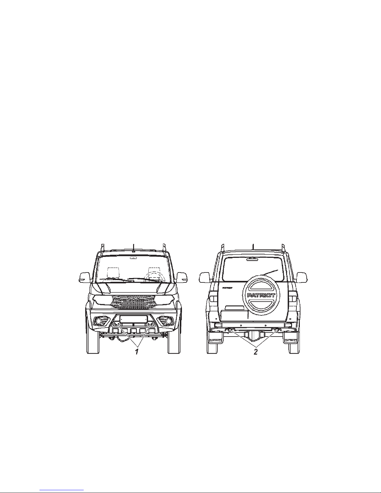
95
Chapter 8. VEHICLE TOWING
The front and rear parts of the frame (Fig. 8.1) are equipped
with towing eyes for flexible towing. Before towing, turn on the
ignition (position I, Fig. 3.4) and light alarm. When towing,
check the tension of the rope. Tow the motor vehicle smoothly,
without jerks.
The towing of a trailer is possible only if the vehicle is equipped
with a ball-type tow hitch.
WARNING! Remember that when the engine turns off, the
forces required for steering input and motor vehicle braking increase
significantly.
Strictly follow the requirements listed in "The Highway Code"
when towing.
If the brake or steering system is broken, it is forbidden to drive
or tow the motor vehicle with a tow rope. In this case use the two
wheel towing or tow truck service.
It is strictly forbidden to tow the motor vehicle using the balltype tow hitch!
Fig. 8.1. Towing eyes:
1 — front eyes; 2 — rear eyes
Page 96

96
Chapter 9. VEHICLE MAINTENANCE
The scope and period of the motor vehicle maintenance are
specified in the service book.
The present manual contains the methods of motor vehicle
maintenance and adjustment of its units and also the operations
which should be carried out in the intervals between the
maintenance actions in accordance with the warranty card of
the service book.
Tightening torques of the main threaded joints are shown in
Annex 2 of the present Manual.
DAILY MAINTENANCE
1. Visually check the motor vehicle configuration, the condition
of the body, glasses, rear view mirrors, trim packages, license
plates, painting, door locks, wheels and tires. Eliminate the
detected defects.
Inspect the parking lot of the motor vehicle to make sure
there are no fuel, oil, coolant or brake fluid leakages. Eliminate
the detected leakages.
Check and replenish the coolant, oil in the crankcase, braking
fluid and fuel to the required amount.
2. Check the functioning of the steering system, brake systems,
lighting devices, light and sound alarms, windscreen wiper.
Eliminate the detected defects.
3. Charge the windshield washer tank. Water is allowed for
use in warm seasons.
4. If the motor vehicle was operated in extremely dusty conditions
or crossed fords and country road sections covered with the mud,
check the condition of the filter element of the engine air filter
and replace it, if necessary.
5. Wash the motor vehicle after a trip if it was operated in
dirty or dusty road conditions.
VEHICLE MAINTENANCE
AFTER EVERY 500 KM
1. Check and adjust the tire air pressure as required.
2. Check and tighten the wheel bolts after the first 300–500 km
(if necessary).
Page 97

97
SEASONAL MAINTENANCE
Seasonal maintenance is performed twice a year (in spring and
autumn) and, if possible, combines with the next maintenance
in accordance to the warranty card of the service book.
Prior to the summer season operation
1. Remove the oil pump cover and check the condition of
the oil pump drive gears.
2. Check the operation of the screen wiper and washer.
Eliminate the defects.
3. Replace oils in the units with summer (all-season) grade
oils specified in the lubrication schedule.
Prior to the winter season of operation
1. Check the density of fluid in the engine cooling system
and set the required density (1.075 — 1.085 g/cm3 at 20°C), if
necessary.
2. When filling the washer reservoir with the water, pour off
the water.
3. Check the operation of the body heating and ventilation
systems. Eliminate the defects.
4. Wash the fuel tanks prior to the winter season of operation
(or after 30000 km).
5. Replace oils in the units with winter grade oils specified
in the lubrication schedule.
ZMZ-40906 ENGINE
Engine suspension
During the use of the motor vehicle, check the tightening of
threaded joints of the front and the rear engine suspensions (refer
to Appendix 2) and condition of the supports. Delamination and
breakage of the engine supports is not permitted.
Engine cylinder head
During the use of the engine, the cylinder head bolt tightening
is not required. Perform the tightening only when the engine is
cold, if necessary. In order to provide the tight and even contact
of the cylinder head bolt with the gasket, perform the tightening
in a sequence shown in Fig. 9.1, in two steps. Tighten the bolts
evenly using the torque wrench (refer to Appendix 2).
Page 98

98
Engine gas distribution mechanism
Camshaft drive is a two-stage chain. Chain tension is provided
for by hydraulic tensioners.
WARNING! Do not take the hydraulic tensioner out of the
chain cover to prevent disengagement of the piston with the casing
caused by the wrap spring.
The valves are driven from the camshafts directly via the
hydraulic pushers.Using the hydraulic pushers eliminates the
need for clearances adjustment.
Engine lubrication system
The engine should be stopped immediately when a lubrication
system malfunction is registered.
WARNING! The manufacturing facility set-in reduced size
engine oil filter is to be replaced at the first maintenance service
(after 2500 km, total kilometres logged) on one of the filters:
2101C-1012005-HK-2, 2105C-1012005-HK-2 manufactured by
'KOLAN' company or 409.1012005, 406.1012005-02 manufactured
by LLC 'BIG-Filter' company.
Regularly check up oil in the crankcase and fill it up as required.
Make the check before starting the engine. When checking the
oil level after the engine stops, it is necessary to wait for at least
15 minutes to allow the oil to drain into the crankcase. The
motor has been placed on a horizontal site. The oil level shall
be between MIN and MAX oil level gauge marks 10 (Fig. 9.2).
In case of frequent cross-country road trips, keep the oil level
near the «MAX» mark, not exceeding it. The volume of oil to
be added to the engine between MIN and MAX is 1 liter.
Engine oils of different grades and different manufacturers may
not be mixed! If the engine oil of another grade or manufacturer
is to be poured, you must flush the lubrication system with
washing oil. The washing oil shall be selected in accordance with
the recommendations of the manufacturer of the newly poured
oil.
Fig. 9.1. Sequence of the cylinder
head bolt tightening
Page 99
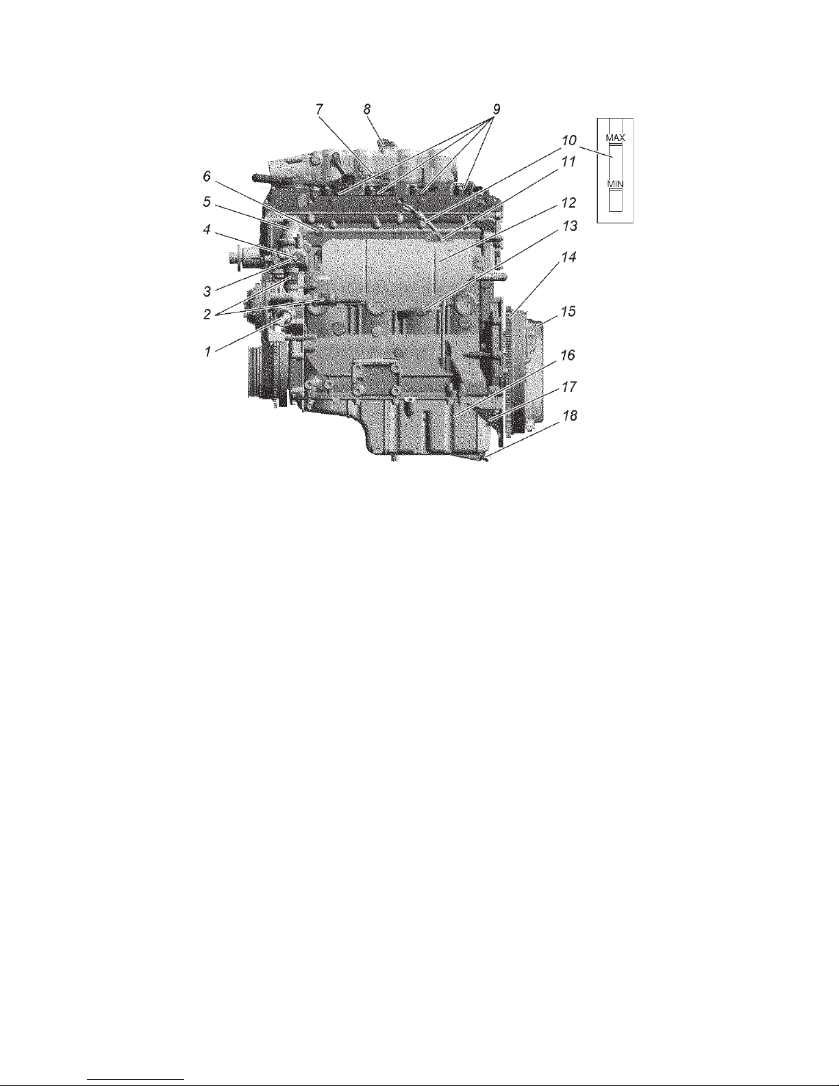
99
When changing the engine oil, replace the oil filter. Drain the
used oil from the engine crankcase immediately after a journey
while it is still hot. In this case, the oil pours out quickly and
completely.
Remove the oil filter 10 (see Fig. 9.3) by turning it counterclockwise. When installing a new filter, make sure that the rubber
O-ring is in proper condition and lubricate it with engine oil,
turn the filter until the O-ring touches the plane on the engine
block and then tighten the filter with a 3/4 turn. Make sure no
oil leak exists.
With the engine warm and the lubrication system intact, the
emergency oil pressure warning lamp may be on at idle, but it
shall go out immediately after increasing the crankshaft rpm.
It is recommended to flush the engine lubrication system after
each two oil changes. For that purpose, drain the used oil, fill
in special flushing oil (VNIINP-FD) 3-5 mm over the "MIN"
Fig. 9.2. Engine ZMZ-40906 (left side view):
1 — Coolant from radiator to water pump supply pipe; 2 — connection hoses;
3 — thermostat housing; 4 — control unit coolant temperature sensor; 5 —
coolant branch pipe from thermostat to radiator; 6 — critically low oil pressure
sensor; 7 — crankshaft position sensor connector; 8 — absolute pressure and
temperature sensor; 9 — ignition coils; 10 — oil level indicator; 11 — engine
elevation rear bracket; 12 — exhaust manifold screen; 13 — exhaust manifold;
14 — flywheel; 15 — clutch; 16 — oil charger; 17 — clutch charger booster;
18 — oil purge plug.
Page 100
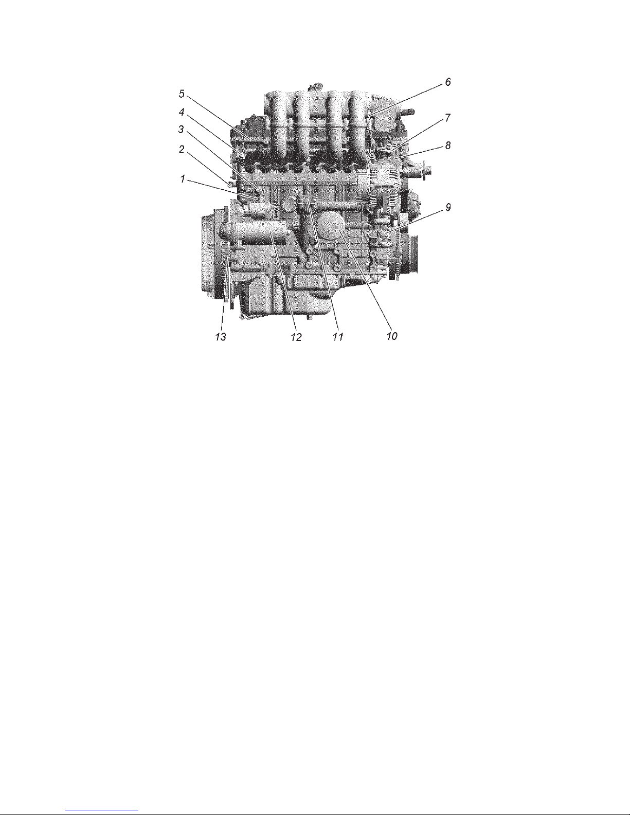
100
mark on the oil level indicator and let the engine run for 10
minutes. Then drain the flushing oil, replace the oil filter and
pour in clean engine oil. If the flushing oil is absent, the flushing
can be carried out using pure engine oil.
Engine crankcase ventilation system
During engine breather system maintenance remove valve cap
4 (Fig. 9.4), ventilation hoses and tubes, vacuum valve cap 3, the
valve membrane and spring and clean the removed parts. Clean
the holes of valve cap ventilation necks, holes 7 of separated oil
drain, sensing hole 8 in the vacuum valve case and venting holes
in the vacuum valve cap. The oil baffle 5 shall be flushed mounted
on the valve cap. Check the membrane for damage and breakage.
When re-assembling, ensure tightness of connections.
WARNING! DO NOT operate the Engine with a non pressuretight ventilation system and open oil socket. It may cause higher
oil consumption via crankcase blow-by gas evacuation and
environmental pollution. To prevent the ventilation system, tight
close the oil socket cap and set the oil level indicator to the fix.
Fig. 9.3. Engine ZMZ-40906 (right side view):
1 — Coolant to heater branch pipe; 2 — heater coolant discharge tube; 3 — knock
sensor; 4 — fuel pipeline flanged socket/union nipple; 5 — common rail with
injectors; 6 — «-» KMCUD wire connection pin; 7 — upper hydraulic tensioner
cap; 8 — engine elevation front bracket; 9 — lower hydraulic tensioner cap;
10 — oil filter; 11 — oil pump drive cap; 12 — Starter; 13 — gear installation pin
 Loading...