


USER’S MANUAL

EasyTravel – ET1B User’s Manual Rev. 0708 2

EasyTravel – ET1B User’s Manual Rev. 0708 3
Table of contents:
Page
1. Introduction 4
2. Safety 4
3. System Components 5
4. Assembly and Folding Instructions 7
5. Operating Your EasyTravel 10
6. Moving and Transporting Your EasyTravel 14
7. Helpful Hints for Everyday Use 16
8. General Maintenance and Inspection 17
9. EMI – Electromagnetic interference 19
10. Fault Finding 22
11. Disposal and Recycling 23
12. Technical Data 23
NOTE: Design details may change without notice.

EasyTravel – ET1B User’s Manual Rev. 0708 4
1. INTRODUCTION
The EasyTravel is a “Class A” Electrically powered scooter. It is intended to
be used by individuals that are able to walk, but suffer from mild mobility limi-
tations. The user must have sufficient arm and leg strength to get on and off
the EasyTravel alone and to safely steer under all driving conditions.
The EasyTravel is intended for indoor and restricted outdoor use on pave-
ments or paved footpaths only during daylight hours. The EasyTravel does
not have lights and reflectors and therefore must not be used in the dark or in
limited visibility conditions.
CAUTION: Failure to follow the instructions contained in this manual may result in injury to the user or to other persons.
2. SAFETY
During your initial use of the EasyTravel we recommend caution as you prac-
tice operating the unit in various situations. Keep the speed at a reduced level
until you are comfortable controlling the scooter. Follow the safety tips and in-
structions and you will be comfortable manoeuvring through doorways, on
and off lifts, over moderate terrain and up and down ramps.
These safety considerations and tips will help you to operate the EasyTravel
safely. The EasyTravel is a powerful electric vehicle; these rules will help you
prevent personal injury and damage to your scooter.
1. Read this manual and all labels before operating.
2. Do not carry passengers or exceed the maximum weight capacity.
3. Do not mount or dismount the EasyTravel unless it has come to a full
stop and is turned off.
4. Do not back up on to uneven inclines or surfaces.
5. Always switch the speed selector to low when driving in a confined space.
6. Always reduce speed when turning.
7. Do not operate your scooter when under the influence of alcohol, medica-
tions or drugs that may impair your safety.
EasyTravel – ET1B User’s Manual Rev. 0708 5
8. Always keep your feet on the foot platform when driving.
9. Do not sit on the scooter while being transported in a moving vehicle. Al-
ways fold down and secure your EasyTravel and transfer yourself to a
vehicle seat.
3. SYSTEM COMPONENTS AND DETAILS
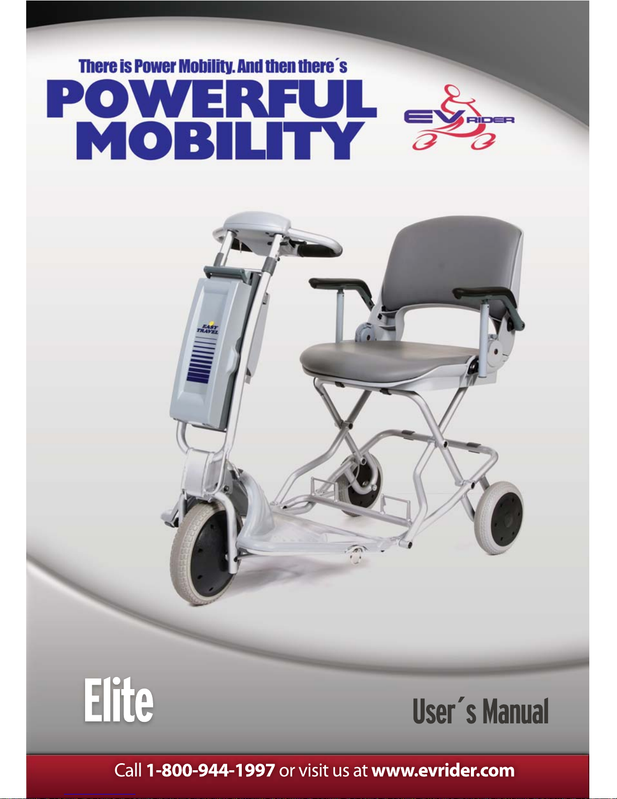
3.1. EasyTravel parts – (Figure 1)
1. Battery pack (detachable) 11. Rear wheel
2. Front column (detachable) 12. Folded frame lock/release pin
3. Column lock/release triggers 13. Unfolded frame lock/release pin
4. Controller cover 14. Utility basket (holding capacity
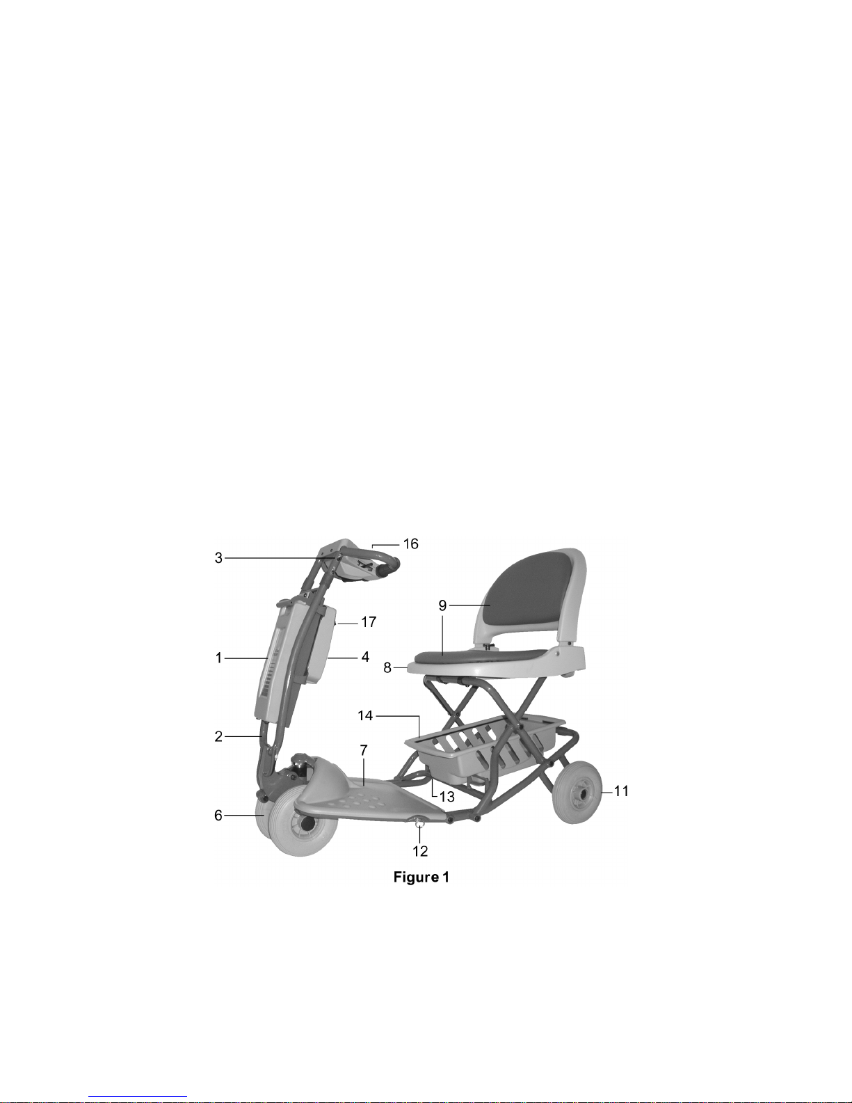
5. Charging socket (Fig. 1A) 20lbs/9kg)
6. Front drive wheels 15. Charger and connecting cables
7. Foot platform (Fig. 1B)
8. Seat shell 16. Control Panel
9. Seat cushions 17. Freewheel switch
EasyTravel – ET1B User’s Manual Rev. 0708 6
3.2. Control Panel – (Figure 2)
1. Switch
2. Hand control lever (right and left)
3. Speed adjusting knob
4. Indicator light (LED)
5. Battery gauge
6. Hand-grips
3.3. EasyTravel Optional Accessories:
1. Extra battery pack
BELL: If the user requires an audible warning device, a standard bicycle bell
can be attached to the handlebar.
EasyTravel – ET1B User’s Manual Rev. 0708 7
4. ASSEMBLY AND FOLDING INSTRUCTIONS
4.1. Assembling your EasyTravel
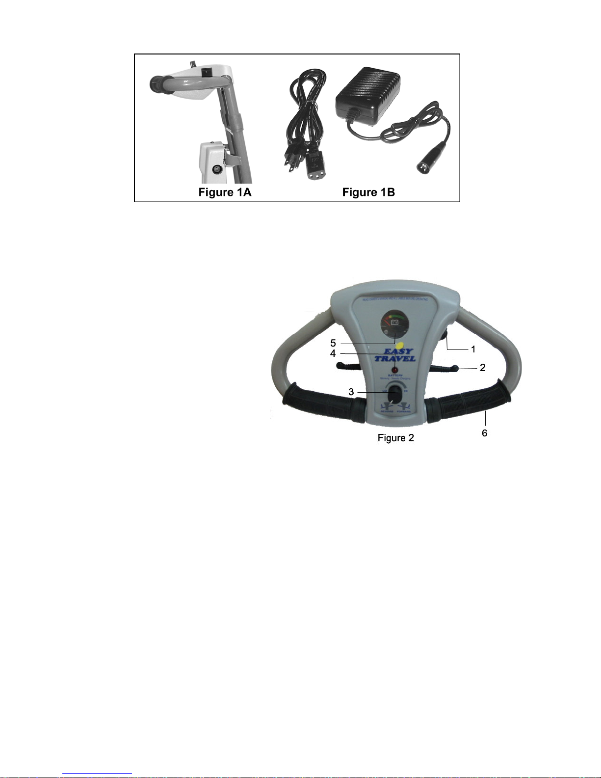
Unfolding Rear Frame
Pull on the folded frame lock pin ring (Fig.
4/1) to release the foot platform and unfold
the frame. Pull the seat backrest (Fig. 4/2)
and lift it to the upright position. Ensure that
the unfolded frame lock pin secures the
platform in the horizontal position.
Unfolding Front Column
Pull the column lock triggers (Fig. 4/3)
upward towards the handle to release the
tilt lock. Move the drive unit away from the
column (all the way) to open the quick-
release housing. This is the column
“detach” position.
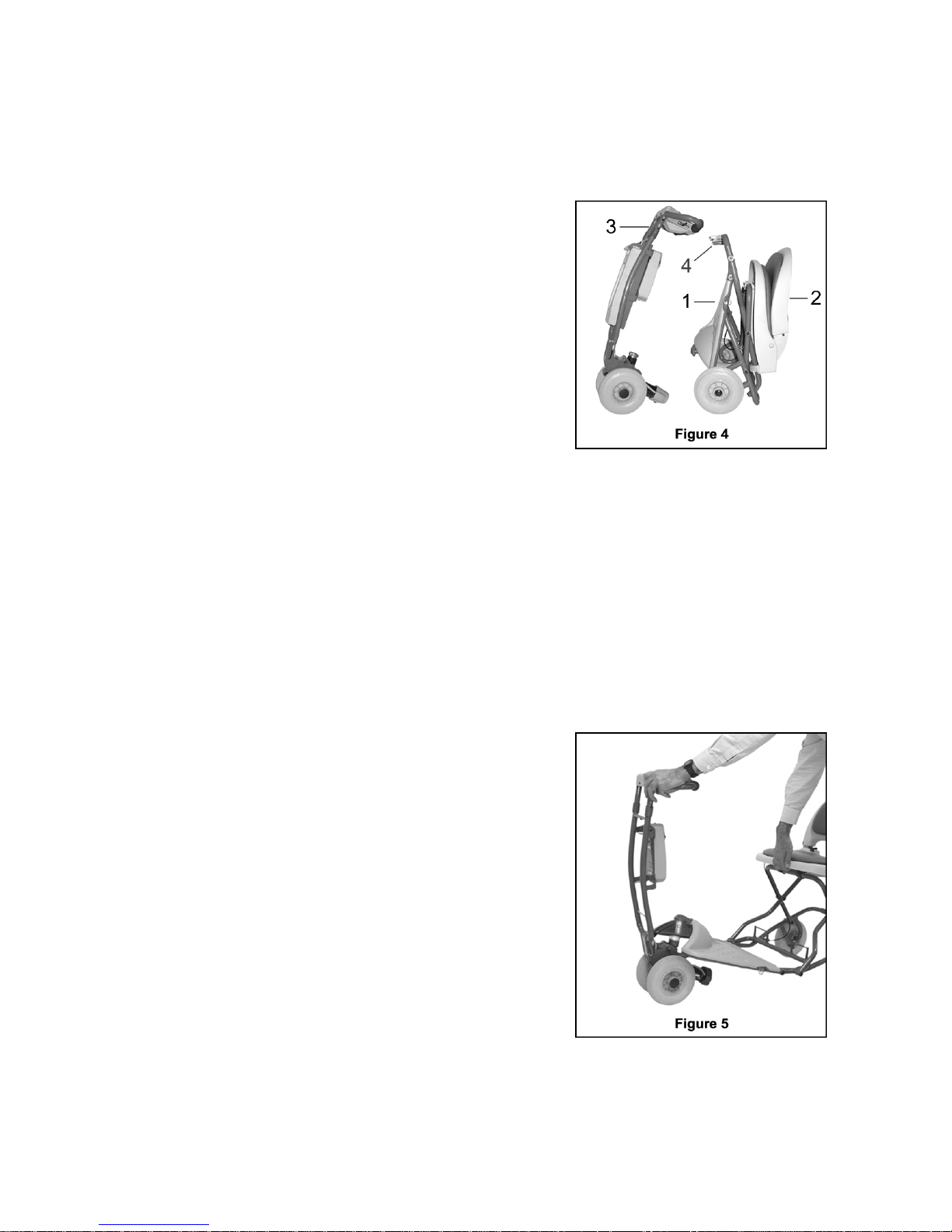
Connecting the Front Column to the
Rear Frame
Position the column in the “detach” position.
Lift the front of the Foot platform and insert
connection pin into the quick-release
housing on the drive unit. This may be done
without bending down by lifting the front of
the seat “lip” while holding the front column
hand-grip as shown in Fig. 5.

EasyTravel – ET1B User’s Manual Rev. 0708 8
Front Column Adjustment (Figure 6)
To adjust the angle of the front
column, pull the column lock triggers
upward. Move the column into the
desired position and release. Push
lightly back and forth on the column to
ensure that it is locked in the desired
position.
1. For driving the EasyTravel, adjust
column to the rear-most position.
2. For getting in and out of the
EasyTravel seat comfortably, the
column may be moved away from
the seat to the entry/exit position.
3. For detaching the front column
from the rear frame, adjust the
column fully forward to the detach
position (Fig. 6/3); remove battery
before adjusting the column to the
detach position.
CAUTION: When getting in and out of the EasyTravel seat, step only on
CENTER of foot platform. DO NOT STEP ON SIDE OF FOOT PLATFORM
to avoid tipping the EasyTravel.
NOTE: The rear frame, when folded, can be lifted by the handles (Fig 4/4).

EasyTravel – ET1B User’s Manual Rev. 0708 9
4.2. Folding and Unfolding your EasyTravel
Folding the EasyTravel
Step 1: Fold backrest of seat down and ensure it is locked (Fig. 7/1)
Step 2: Hold handgrip of front column (Fig. 7/2) in the “Operating” or
“Entry/Exit” position and push forward away from seat to fold
platform upwards.
Step 3: Grasp platform
handle (Fig. 7/3)
and pull column
lock triggers (Fig.
7/4) to fold column
towards the
platform. Fold
together until
folded frame lock
pin (Fig. 7/5) and
column latch (Fig.
7/6) click into
place and hold EasyTravel in folded position.
Unfolding the EasyTravel
Step 1: Pull on the frame lock pin ring (Fig. 8/1) to release platform and rest
front wheels on floor.
Step 2: Pull the seat
backrest and lift it
upright. (Fig. 8/2)
Step 3: Grasp top of seat
backrest (Fig. 8/3)
and pull column
lock triggers (Fig.
8/4) to release
column from
platform. Pull
outwards to unfold
EasyTravel until
platform and column lock into the operating position.

EasyTravel – ET1B User’s Manual Rev. 0708 10
5. OPERATING YOUR EasyTravel
5.1. Control Panel operation features
The switch located on the right side of the control panel (Fig. 9/1), will turn
the power of the EasyTravel ON or OFF.
NOTE: Turn your EasyTravel switch to the OFF position when not in use
in order to conserve battery power, and prevent unintentional operation.
The top speed may be adjusted by turning the Speed-adjusting knob (fig
9/3). By turning the knob to the HI position, your EasyTravel's top speed
will be up to 3.7mph/6kph. When the knob is set to the Lo position, the
speed will be reduced to a slow crawl, ideal for less experienced drivers
and for operating indoors.
5.2. Battery indicator Light (Fig. 9/4)
The light, located at the bottom of the handle control cover, displays bat-
tery status and fault indications as follows:
Indicator light steady - This indicates that all is well.
Indicator light flashes slowly - The controller is functioning cor-
rectly but batteries should be charged as soon as possible. The Bat-
tery Level Indicator (Fig. 9/5) shows the charge that is left.

EasyTravel – ET1B User’s Manual Rev. 0708 11
Blinking - Needs Charging
BATTERY
FORWARD
REVERSE
SPEED
LO HI
BATTERY
REVERSE FORWARD
SPEED
Blinking - Needs Charging
LO HI
BATTERY
REVERSE FORWARD
SPEED
Blinking - Needs Charging
LO HI
Indicator light flashes rapidly - This indicates that there is a fault.
Please follow the following procedure:
1. Switch off the EasyTravel
2. Make sure that the EasyTravel is not in the FREEWHEEL posi-
tion.
3. Make sure that the charger is not connected to the EasyTravel.
4. Make sure that the control lever is in the middle position.
CAUTION: If control lever does not return by itself to the middle po-
sition - do not operate. Contact your service agent.
5. Switch the EasyTravel on again and check the indicator light. If
it flashes rapidly again, switch off and do not operate. Contact
your service agent!
5.3. Battery Gauge(Fig. 9/5)
The Battery Gauge (Fig. 9/5) shows the battery charge that is left.
5.4. Driving your EasyTravel
To drive forward, pull the right side of the hand control lever towards you
(Fig. 10/1). You can also move forward by pushing the left side of the
control lever away from you. By releasing the control lever, you will
gradually come to a stop, and the EasyTravel brake will be applied
automatically. To operate in reverse, pull the left side of the hand control
lever towards you (Fig. 10/2).
Figure 10

EasyTravel – ET1B User’s Manual Rev. 0708 12
5.5. Safety considerations when driving your EasyTravel
Footpaths and sidewalks appear to be level but are usually slightly
sloped for drainage of rainwater. Counter-steering may be necessary
for overcoming excessive slopes. In such cases the speed should be
reduced as necessary.
When approaching ditches, bumps or similar obstacles – reduce
speed as necessary.
Do not operate EasyTravel in places or on surfaces where a loss of
wheel grip could be hazardous, for example on wet grassy slopes.
5.6. Armrests (optional)
To enable easier entry to and exit from
your EasyTravel the armrest can be
lifted, see Fig. 10A.
5.7. Batteries
Battery information
The EasyTravel is designed to use sealed lead acid, maintenance-free,
12V batteries.
Always turn your EasyTravel OFF before removing and installing batteries. To get the maximum out of your batteries, it is recommended to fully
charge the batteries overnight after every day of use. Reconnecting the
charger when the batteries are partially discharged or fully charged
will not harm them. Extended charging is good for the batteries and you
cannot overcharge them.
Battery range depends on operator weight, terrain and the condition of
batteries used. Charge your batteries daily and/or overnight when the
EasyTravel is not in use.
Battery Recharging Instructions
To recharge, turn off EasyTravel It is possible to either charge the battery
while connected on the EasyTravel (see instruction 1 below) or directly
(instruction 2).

EasyTravel – ET1B User’s Manual Rev. 0708 13
1. Plug the charging connector into the EasyTravel charging socket and
then connect the charger to an electrical outlet socket.
2. Plug the charging connector in the back of the battery pack and then
connect the charger to an electrical outlet socket.
During charging, the indicator light on the charger will be orange. When
the battery is approaching full charge the indicator light will turn green. In
order to achieve the maximum battery capacity and efficiency, it is advised to charge them overnight, and at least four hours after the indicator
light has turned to green.
Safety Instructions
CAUTION: Failure to follow these instructions may result in personal injury or property damage.
1. Never smoke or allow an open flame in the vicinity of the batteries.
2. Use the charger for charging lead acid batteries only. It is not intended to supply power to an extra-low-voltage electrical system or to
charge dry cell batteries.
3. Never charge a frozen battery.
4. Do not operate the charger in a closed-in area or restrict ventilation.
5. Prevent external damage to AC and DC cords. Do not use charger if
cords are damaged.
6. Connect DC charging cord to the Charging Socket before connecting
charger AC supply cord to the electrical outlet, and disconnect the AC
cord from the electrical outlet before disconnecting charge cord.
7. Be extra cautious not to drop a metal object onto the battery case.
8. Remove jewellery.
Battery Storage
Before storage, battery packs should be fully charged, and should
be recharged at least once every three months.
Store batteries indoors in a dry environment.
Storage temperature range: -20ºC (-4ºF) to 40ºC (104ºF)
Charging temperature range: 0ºC (32ºF) to 40ºC (104ºF)
Operating temperature range: -20ºC (-4ºF) to 50ºC (122ºF)

EasyTravel – ET1B User’s Manual Rev. 0708 14
WARNING: Store batteries in the 'correct' position. (See Fig. 14).
Battery Replacement and Disposal
The EasyTravel battery pack contains two 12V maintenance-free batteries. Replacement of the batteries is only permitted to an authorized
dealer.
Battery cells may emit minor acid fumes.
Batteries must be recycled. Disposals of potentially damaged batteries
present hazards of injury from acid leakage and environmental pollution.
NOTE: When removing a battery, always set it on cardboard, newspaper,
or surfaces that cannot be damaged by acid fumes or liquid from the battery.
6. MOVING AND TRANSPORTING YOUR EasyTravel
6.1. Moving Your EasyTravel in Freewheel Mode when unfolded:
The Freewheel switch (Fig. 1/17) is used for releasing the brake and
moving the EasyTravel without operating the motor. Before activating,
make sure your EasyTravel is switched on. Turn Freewheel switch to the
"freewheel" position and push or pull the EasyTravel manually.
NOTE: The Freewheel mode can only be activated after the battery is in
place and the power switch (Fig.9/1) is turned on. Doing otherwise will
cause a fault situation indicated by rapid flashing of the Indicator light
(Fig. 9/4). See section 4.2.
The EasyTravel is fitted with an electromagnetic breaking mechanism.
WARNING: The Freewheel switch should never be engaged on a slope.
CAUTION: The seat back must remain in the upright position.

EasyTravel – ET1B User’s Manual Rev. 0708 15
6.2. “Walking” your EasyTravel in the
folded position
The folded EasyTravel may be pulled
along suitcase style. The battery should
be carried separately (Fig. 11) or in the
utility basket. See folding instructions on
page 8.
6.3. Transporting Your EasyTravel
Quickly And Easily
Your EasyTravel can be disassembled
and transported in most car trunks.
When disassembling for transportation or
storage:
1. Disconnect battery pack and place in
Utility basket (Fig. 12/1)
2. Disconnect front column (Fig. 12/2)
and fold rear frame separately (Fig.
12/3)
3. For storage – set down front column
in a stable position.
4. For transportation, place EasyTravel
components in car trunk as shown in
figure 13.

EasyTravel – ET1B User’s Manual Rev. 0708 16
7. HELPFUL HINTS FOR EVERYDAY USE
Before using your EasyTravel take the following precautions:
• Ensure that the front column and rear frame are locked together.
• Ensure that the rear frame is locked open.
Speed Controls
Always operate your EasyTravel at a reasonable speed for both your per-
sonal safety and others.
Stopping
Dynamic braking will gradually bring your EasyTravel to a stop when hand
control lever is released.
Ramps and Inclines
Lean forward and carefully manoeuvre your EasyTravel up a ramp or incline.
Be aware that not all ramps are constructed according to Government stan-
dards. The Government standard for wheelchair ramps is 2.5 cm (1 inch) rise
per 30 cm (1 foot).
Lower the speed setting to a slow speed when descending inclines.
Using an elevator
Backing into an elevator allows you to exit forward. Be sure that the elevator
is level with the floor.
Opening Doors
When a door opens towards you, approach at an angle and just off to one
side. Adjust the speed knob to a low setting. Grasp the doorknob, reverse
and pull the door open. For doors that open away from you, position the front
roller against the door, close to the doorjamb on the doorknob side of the
door. After you release the latch, use the roller to push the door open.
WARNING: Be careful with glass doors to avoid personal injury!

EasyTravel – ET1B User’s Manual Rev. 0708 17
8. GENERAL MAINTENANCE AND INSPECTIONS
Minimum maintenance should prevent unnecessary repairs.
Keep Your EasyTravel Shining
Wipe the seat clean with a damp cloth. Protect the painted parts with a coat
of auto wax.
WARNING: Water or Excessive moisture around the controller unit or electri-
cal connections may cause contamination of electrical circuitry, damage and
malfunction as well as personal injury. Do not leave your EasyTravel in the
rain or in excessively humid locations.
Daily Checks
With the EasyTravel switched off, check that the hand control lever me-
chanism returns to the rest position when you push and release. If there is a
problem do not use the EasyTravel and contact your authorized dealer.
Weekly Checks
1. Throttle test: Pull the throttle to the full speed position and switch ON
the Power switch. The EasyTravel should not move and the LED on the
panel should flash. If the EasyTravel does move – do not use your
EasyTravel. Contact your authorized dealer.
2. Automatic brake and drive test: This test should be carried out on a
level surface with at least 3’ / 1 m. clear space around the EasyTravel:
Switch the EasyTravel on.
Move the control lever only slightly in the forward direction until you hear a
“click” when the brake disengages. The EasyTravel should start to move
forwards slowly.
Immediately release the throttle. You must be able to hear a “click” when
the brake engages back, within a few seconds.
Repeat the test in the reverse direction.
If you do not hear the brake operating, or the EasyTravel does not move
slowly in the expected direction – do not use your EasyTravel. Contact your
authorized dealer.

EasyTravel – ET1B User’s Manual Rev. 0708 18
Monthly Care
Clean upholstery, plastic and metal parts with a mild surface cleaner.
CAUTION: Keep cleaning solvents away from electrical wires and connectors.
Half-Year Care:
1. Apply a lubricant/cleaner (such as WD40 or similar) these locations:
Column tilt lock pin and housing.
Unfolded lock pin and housing.
Battery pack lock pins.
2. Lightly apply Vaseline or similar lubricant to battery contact pins and
springs on front column.
3. Check for tire wear.
Overload Fuses
The electric circuits of the EasyTravel are provided with two overload protec-
tion fuses. Replacement of the fuses is only permitted to an authorized tech-
nician. Both fuses are commercially available automotive-blade type.
Location of the fuses
Battery Pack fuse 20A, - Within Battery pack
Control circuit fuse 1A, – Underneath controller cover
NOTE: Fuses of a different rating should not be used!
WARNING: Do not attempt to repair or service the EasyTravel or any of its
components, as this will void your warranty.
SERVICE AND REPAIR: CONTACT YOUR AUTHORIZED DEALER.

EasyTravel – ET1B User’s Manual Rev. 0708 19
9. EMI – ELECTROMAGNETIC INTERFERENCE
CAUTION: It is important that you read this information regarding the possi-
ble effects of electromagnetic interference on your EasyTravel.
Electromagnetic Interference (EMI) From Radio Wave Sources
Motorized scooters may be susceptible to electromagnetic interference (EMI),
which is interfering electromagnetic energy (EM) emitted from sources such
as radio stations, TV stations, amateur radio (HAM) transmitters, two-way ra-
dios, and cellular phones. The interference (from radio wave sources) can
cause scooters to release their brakes, come to a sudden stop, or move in an
uncontrolled manner. It can also permanently damage a scooter’s control sys-
tem. The intensity of the interfering EM energy can be measured in volts per
motor (V/m). Each Motorized scooter can resist EMI up to a certain intensity.
This is called its “immunity level". The higher the immunity level, the greater
the protection. The FDA has stated that all newly manufactured electric mobil-
ity vehicle models should have a resistance of at least 20 V/m, which would
provide a reasonable degree of protection from the more common sources of
radiated EMI.
Your EasyTravel as shipped, with no further modification, has an immunity
level of 20 V/m. This immunity was tested with the inclusion of these accesso-
ries: a utility basket with a spare battery-pack and the charger unit carried in-
side it.
There are a number of sources of relatively intense electromagnetic
fields in the everyday environment. Some of these sources are obvious
and easy to avoid. Others are not apparent and exposure is unavoid-
able. However, we believe that by following the warnings listed below,
your risk to EMI will be minimized.

EasyTravel – ET1B User’s Manual Rev. 0708 20
The sources of radiated EMI can be broadly classified into three types:
1) Hand-held portable transceivers (transmitters-receivers) with the an-
tenna mounted directly on the transmitting unit. Examples include citi-
zens band (CB) radios, "walkie-talkies”, security, fire, and police trans-
ceivers, cellular telephones, and other personal communication devices.
**NOTE: Some cellular telephones and similar devices transmit signals
while they are ON, even when not being used;
2) Medium-range mobile transceivers, such as those used in police cars,
fire trucks, ambulances, and taxis. These usually have the antenna
mounted on the outside of the vehicle; and
3) Long-range transmitters and transceivers, such as commercial broad-
cast transmitters (radio and TV broadcast antenna towers) and amateur
(HAM) radios.
NOTE: Other types of hand-held devices, such as cordless phones, laptop
computers, AM/FM radios, TV sets, CD players, and cassette players, and
small appliances, such as electric shavers and hair dryers, so far as we know,
are not likely to cause EMI problems to motorized scooters.
Motorized scooter Electromagnetic Interference (EMI)
Because EM energy rapidly becomes more intense as one moves closer to
the transmitting antenna (source), the EM fields from hand-held radio wave
sources (transceivers) are of special concern. It is possible to unintentionally
bring high levels of EM energy very close to the motorized scooter’s control
system while using these devices. This can affect the scooter’s movement
and braking. Therefore, the warnings listed below are recommended to pre-
vent possible interference with the control system of your EasyTravel.

EasyTravel – ET1B User’s Manual Rev. 0708 21
WARNINGS
Electromagnetic interference (EMI) from sources such as radio and TV sta-
tions, amateur radio (HAM) transmitters, two-way radios, and cellular phones
can affect motorized scooters. Following the warnings listed below should re-
duce the chance of unintended brake release or powered wheelchair move-
ment, which could result in serious injury.
1) Do not operate hand-held transceivers (transmitters-receivers), such as
citizens band (CB) radios, or turn ON personal communication devices,
such an cellular phones, while your EasyTravel is turned ON;
2) Be aware of nearby transmitters, such as radio or TV stations, and try to
avoid coming close to them;
3) If unintended movement or brake release occurs, turn your EasyTravel
power switch OFF as soon as it is safe to do so;
4) Be aware that adding accessories or components, or modifying your
EasyTravel, may make it more susceptible to EMI (Note: There is no
easy way to evaluate their effect on the overall immunity of your Easy-
Travel);
5) Report all incidents of unintended movement or brake release to your Au-
thorized EasyTravel dealer or service centre, and note whether there is a
source of EMI nearby.

EasyTravel – ET1B User’s Manual Rev. 0708 22
10. FAULT FINDING
Hereunder are some types of disorders, which can usually be repaired rather simply. If these following measures are unsuccessful, contact your authorized dealer!
Problem Check Point
The driving of the wheelchair is
too slow or insufficient, the status
indicator lamp flashes slowly
Batteries are exhausted and need to be
recharged
1 flash
The battery needs charging or there is a
bad connection to the battery. Check the
connections to the battery or charge batteries.
2 flashes
There is a bad connection to the motor.
Check all connections between the motor and the controller.
3 flashes
The motor has a short circuit to a battery
connection.
4 flashes
Freewheel is engaged.
5 flashes
Not used.
6 flashes
The controller is being inhibited from
driving; this may be because the battery
charger is connected.
7 flashes
A throttle fault is indicated. Make sure
that the throttle is in the rest position before switching on the scooter
8 flashes
A controller fault is indicated. Make sure
the controller connections are secure.
9 flashes
The parking brakes have a bad
connection. Check the parking brake
and motor connections. Make sure the
controller connections are secure.
The EasyTravel
does not function,
the Battery/Status
indicator flashes
rapidly.
Count the number
of flashes:
10 flashes
An excessive voltage has been applied
to the controller. This is usually caused
by a poor battery connection. Check the
battery packs and controller
connections.

EasyTravel – ET1B User’s Manual Rev. 0708 23
11. DISPOSAL AND RECYCLING
The packing material must be separated to plastic and pa-
per/cardboard components and submitted to authorized recycling lo-
cations.
The EasyTravel device consists of electronic components, cables,
plastic parts, steel and aluminium frame and adapter parts. Do not
discard of any components to normal garbage facilities. When
EasyTravel is no longer operational, it is to be dismantled and sepa-
rated into above material groups and submitted to authorized recy-
cling facilities.
12. TECHNICAL DATA
*The actual range depends on the operation conditions and the load
Speed Continuously adjustable, up to 6 km/h (3.7 mph)
Power Supply 24 V from Two rechargeable maintenance-free
Sealed Lead/acid batteries
Standard size: 12V – 7.2 Ah
Jumbo size: 12V-12 Ah
Charging time 7 – 10 hours
Max. admissible slope 6 o (10 %)
Max. negotiable curb
height
5 cm / 2”
Range approx.* Standard battery 6.5 - 8 km / 4 - 5 Miles
Jumbo battery 11 – 13 km / 6.5 – 8 Miles
Tires Flat-free PU 200 x 50
Dimensions: 57 X 104 X 86 cm / 22”X41”X34”
Weights:
Rear frame 12.9 Kg / 28.5 Lb
Front column (without
battery)
8.6 Kg / 19 Lb
Battery Pack Standard: 6.5 Kg / 14.5 Lb.
Jumbo: 9.2 Kg. / 20.2 Lb.
Total weight 28 Kg / 62 Lb.
Maximum users weight 114 Kg. / 250 lb.

EasyTravel – ET1B User’s Manual Rev. 0708 24
WARRANTY
The warranty period for the EasyTravel is twelve months and covers faulty
materials and workmanship (consumables not covered: tyres, upholstery,
lamp bulbs, plastic coverings and batteries). Worn parts damaged as a result
of excessive loading, improper handling, intentional damage or unauthorized
maintenance or modification are not covered by the warranty.
For safety and for warranty assurance reasons, any modifications and repair
of the EasyTravel or its components must be performed exclusively by au-
thorized personnel and exclusively with original spare parts.
The EasyTravel and its accessories have been designed, manufactured and
tested in accordance with the specification of the following:
DIRECTIVE: Medical devices 93/42 EEC
Manufactured by: Distributed by:
EC Authorized Representative:
Medical Specialities Ltd.
Blackburn, BB2 4HT UK
EV-RIDER, LLC.
Toll Free: (800) 944-1997
Phone: (239) 278-5054
Fax: (239) 278-1431
6410 Arc Way, Suite A
Fort Myers, FL 33966
www.evrider.com
info@evrider.com
 Loading...