

Page 1

1
TZ-RD05
(TAG06B)
---User Manual
Page 2

2
1 Product Overview
TZ-RD05 is a card reader that designed to read all kinds of RFID tags in the long
range of the radio frequency,using the universal ISM 2.4G ultra low power microwave
frequency band remote identification communication equipment. TZ-Tag06B tag
using the active way through the wireless transmission of information from the
tag,then TZ-RD05 receive information and process through the RS485, LAN and then
sent to other devices for data processing applications.
TZ-RD05 card reader uses a 32 bit ARM processor with high performance,wide
voltage input port with support,lightning protection,anti-static and shell with
dustproof and waterproof protection, which has good stability and high speed data
processing capabilities, and can support a variety of data formats,repeated reading
technology,dynamic key encryption and authentication, to ensure data security,prevent
eavesdropping and crack data link
2 Key Functions
Support RS-485;
Support LAN;
One digital output,can control multiple peripherals;
External special USB configure interface, user can configure RD05 operating
module;
Prevent collision: advanced technology to prevent the collision, can identify
more than 100 per second, at the same time without interference;
Security: encryption algorithm and certification to ensure data security, to
prevent the data link eavesdropping and data to be cracked
The installation type suction a top, concise and beautiful
3 Product Specification
RF frequency
433M
Receiving Sensitivity
-104dBm
Tag identification Angle
3D
Interface
RS485/LAN
Firmware update
Support
Tag protocol
Private protocol
Supply power
DC9V-24V
Net weight
0.15kg
Page 3

3
Operating tem.
-40°C~+60°C
Operating hum.
5% ~ 95% (non-condensing)
IP level
IP55
Dimension
Cylindrical, diameter 170mm,high 40mm
Installation method
Suction top mounting
Extra interfaces:
LAN light
LAN connecting indicator light
LAN
Use to connecting the net
USB
Use specially designed USB cable connect to PC
Signal
Flash one time when receive on Tag
Power supply
Bright when having power supply
POWER
DC9—24V
Internal interfaces:
5PIN port, including the RS485 port, export OUT port, upgrade port, and then we
will be equipped with a 5PIN interface for the user to use the need
5PIN port
Page 4

4
Wire number
Function
Color
note
PIN1
A
black
RS485
PIN2
B
Red
RS485
PIN3
OUT
White
Output port
PIN4
BT_S
Yellow
Upgrade, SOS
PIN5
GND
Orange
GND
4 RS485/LAN Data Protocol
4.1 Contains the TZ-RD05 ID data format
Begin character (7E) + Data length (1byte) + TZ-RD05 ID(3bytes) + Tag ID
(4byte) + Tag state (1byte) + battery voltage (2byte) + temperature (2byte) +
Humidity (1byte) + Check code(1byte) + end code (03)
4.2 Doesn’t Contains the TZ-RD01 ID data format
Begin character (7E) + Data length (1byte) + Tag ID (4byte) + Tag state (1byte)
+ Battery voltage (2byte) + Temperature (2byte) + Humidity (1byte) + Check
code(1byte) + End code (03)
4.3 Contains the TZ-RD05 ID data and RSSI value format
Begin character (7E) + Data length (1byte) + TZ-RD01 ID (3byte) + Tag ID
(4byte) + Tag state (1byte) + Battery voltage (2byte) + Temperature (2byte) +
Humidity (1byte) + RSSI(1byte) + Check code(1byte) + End code (03)
4.4 Doesn’t Contains the TZ-RD05 ID data and Contains RSSI
value format
Begin character (7E) + Data length (1byte) +Tag ID (4bytes) + Tag ID (4byte) +
Tag state (1byte) + Battery voltage (2byte) + Temperature (2byte) + Humidity (1byte)
+RSSI(1byte)+ Check code(1byte) + End code (0S3)
Begin character: 0x7E
Data length: 1byte , After the data length and before the check sum;
TZ-RD01 ID: TZ-RD01 ID depends on the command NO.04
Page 5

5
TAG ID: received tag05/06 ID
TAG status:1 byte (convert to binary)
bit7: Battery voltage status, 1-low Voltage, 0- Voltage normal
;
bit6: Temperature status,1- Temperature more than set high and low
temperature threshold, 0- Temperature normal.
bit5-bit0: reserved;
Battery voltage: 2 byte, Unit: 1mv, 0C 50 means voltage is 3.152V(convert to
decimal)
;
Temperature:2 byte, convert to binary, the first bit of temperature means
normal/abnormal(0-normal,1-abnormal); the second bit of temperature
means positive(+)/negative(-) (0-positive,1-negative) ; after the third bit of
temperature means real temperature, unit:0.1℃(convert to decimal);
For example: 01 64 means +35.6℃, 41 64 means -35.6℃, 80 00 means
abnormal;
Humidity: 1 byte, unit: %;
RSSI: 1 byte,unit:-dBm;
Check code: 1 byte, and the accumulation of all the data before;
End code: 0x03.
The data sample:
7E0D12345662160179000E1000EC4F7203
7E Begin character
0D Data length
123456 TZ-RD05 ID
62160179 Tag ID
00 TAG status
0E10 Battery voltage
00EC Temperature
4F Humidity
72 Check code
03 End code
5 Prepare for configuration
5.1 Ethernet usage
Explain: The language of Ethernet conversion module is Chinese, so if you do
not understand the language, please contact Tzone technical personnel.
Page 6

6
At first connect the machine and router with the cable
Then input 192.168.1.1(base on your gateway)
Input User name and password
User name: admin
Password: admin
Click on the right—DHCP sever--- Client list—find the RD05 IP, and then sign
in
Page 7
7
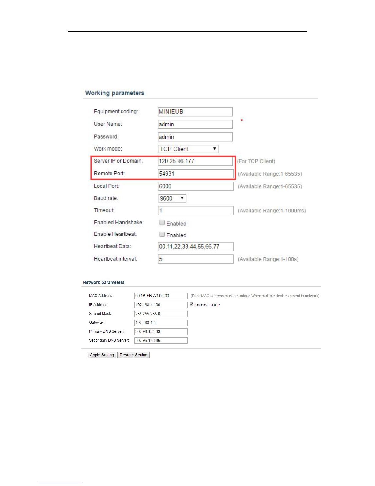
Select--- none, remember the IP then open the IE and input the IP
Enter the account number “admin”, password “admin”.
Ours Server IP :120.25.96.177
Port :54931
Baud rate :9600
According to icon configuration, the default gateway is 192.168.1.1, if the
gateway is different, the corresponding configuration also need to change.
5.2 Install PL2303 windows driver
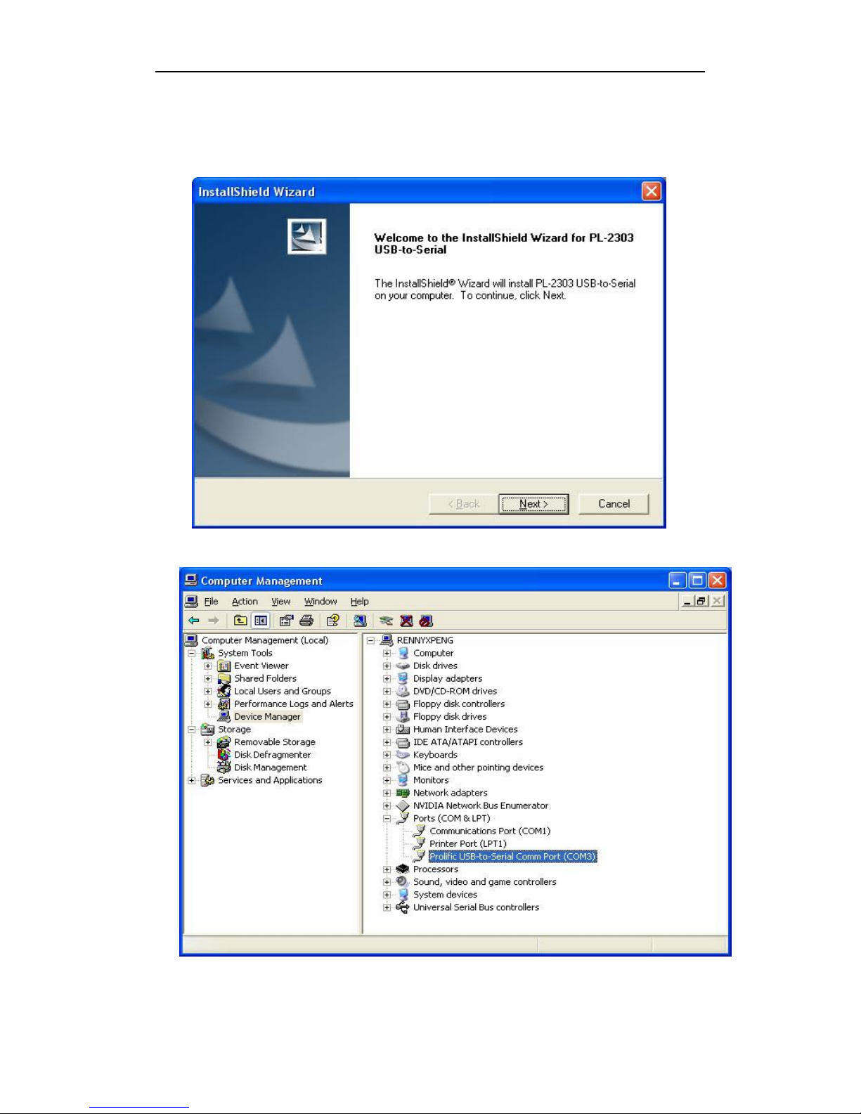
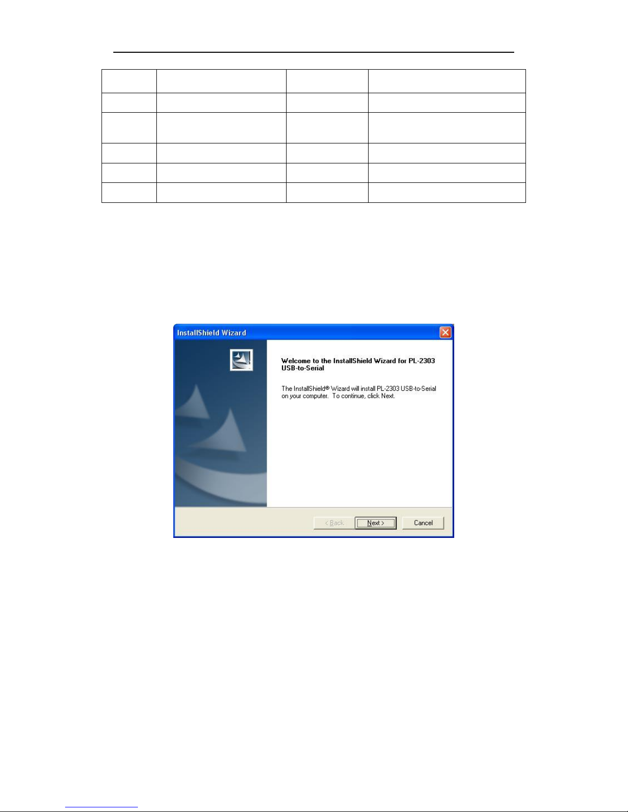
As shown in figure 5-1, the first interface of PL2303 driver. Follow the default
steps, it will be successful like figure 5-2. PL2303 driver build in 2009 is
suggested, you can get it from the website. There is the vision of PL2303 driver
Page 8
8
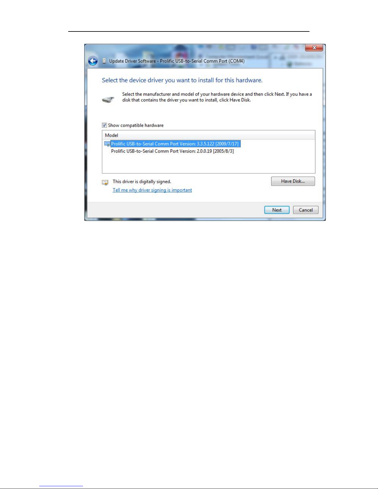
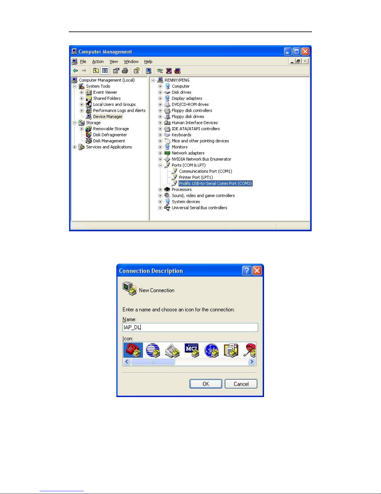
checking way. Device manager---Ports (COM&LPT) ---choose your
COM---right-hand button---Update Driver Software---Browse my computer for
driver software---pick from a list from device drivers---choose 2009 version. As
shown in figure 5-3, I have chosen the version 2009.
Figure 5-1 PL2303 driver installing
Figure 5-2 PL2303 Checking driver
Page 9
9
Figure 5-3 PL2303 choose version 2009/7/17
5.3 Install sscom32
Please download from the Internet or contact sales download sscom32 serial port
tools, and installed on the computer.
5.4 Configure sscom32
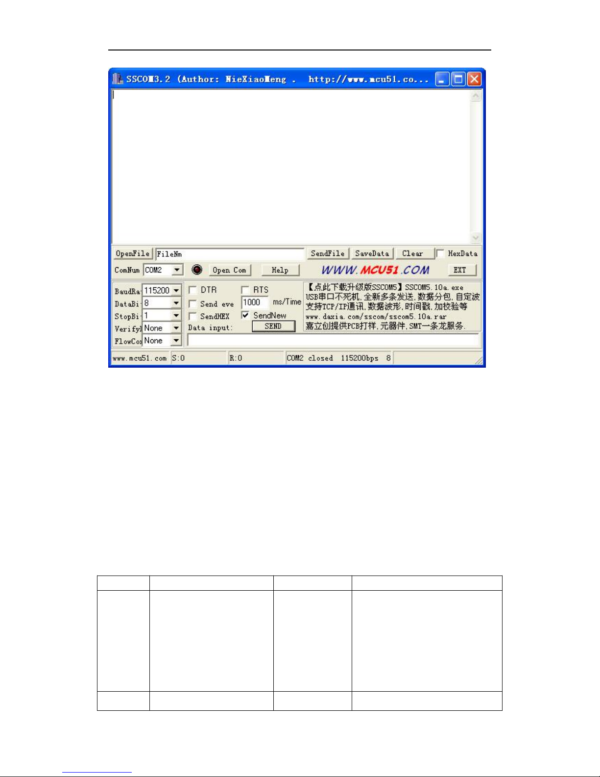
After completing the above steps will USB configure cable inserted into the computer
USB port, and then open the sscom32, choose the corresponding COM port, baud rate
is 115200, data bits is 8, stop bit is 1, parity None, flow control None and then click
open the serial port.
Note: if users to set the parameters of RS232,please also set the response parameters
in sscom32
Page 10
10
5.5 ASCII commands to configure RD05
After completing the above steps to RD05 on electricity, then send the FFF make
machines to enter configuration mode, according to the instruction table 5.1 set up
machine, set up after the completion of the send #DQ make machine to exit the
configuration mode, when the reader receives the TAG information, RS232 and USB
port can output the corresponding information
Table 5.1 TZ-RD05 unify commands
NO.
Instruction
Format
Note
FFF
Enter configure mode
FFF
the instruction can work, after
entering the configuration
mode; And then have to send
command in 10s after entering
the configuration mode,
otherwise it will exit the
configuration mode
00
Set again the stress time
*00,X#
X: [0, 3600], unit 1S, 1 is
Page 11

11
default, 0 will disable this
function
01
Set ID
*01,X#
X:6bits, range [A-F] and
[0-9]
04
Set the serial data
contain RD05’s ID
*04,X#
X:
0-No,default
1-Yes
06
Set the print mode
*06,X#
X:
0-hex (default)
1-ASCII
12
R485 setting
*12,A,B,C,D#
A:baud,[600,128000]
115200 (default) ;
B:digital bits
0-8bit(default) ,
1-9bit;
C:stop bits
0-0.5bit,
1-1bit(default) ,
2-1.5bit,
3-2bit
D:parity bits,
0-none(default) ,
1-Even,
2-Odd
13
data mode setting
*13,X#
X:0- active mode(default)
1- Passive mode
About passive mode: need
upper computer send command
to read data.
Reading command is, AA+ ID
of RD05+ 03 (HEX)
For
example:AA123403(HEX)
14
Output working mode
setting
@14,X,Y,Z#
X:connect time, unit
1s,[0,60];
Y:disconnect time, unit
1s,[0,60];
Z:duration, unit s,
[1-999],999 Indicates that the
action has been continuous
21
Whether to enable the
RSSI values
*21,X#
X-0, Disable(default);
X-1, Enable;
Query command
#D5X
X: command’s NO. For
example, *D51 can query the
Page 12
12
6 Update TZ-RD05 firmware
1) Install USB cable driver
A. At the first, install the Driver for “USB Converter”
B. Connect the RD05 unit to PC through USB cable, View the com port that the
cable used
NO.01
Check all configuration
#DE
Check the firmware
version
#DA
Go to factory setting
#DO
Restart the device
#DR
Out configuration mode
#DQ
Page 13
13
2) Turn on RD05 device
3) Build a New Hyper terminal connect, fill the name, example as IAP_DL
4)Choose the Com Port that the USB Cable used
Page 14
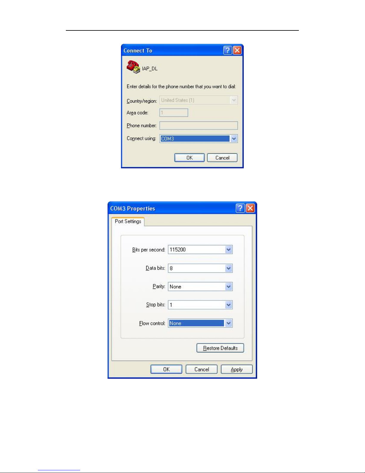
14
5) Setup all the option as shown in the following picture
6) Into Configure Mode
Page 15
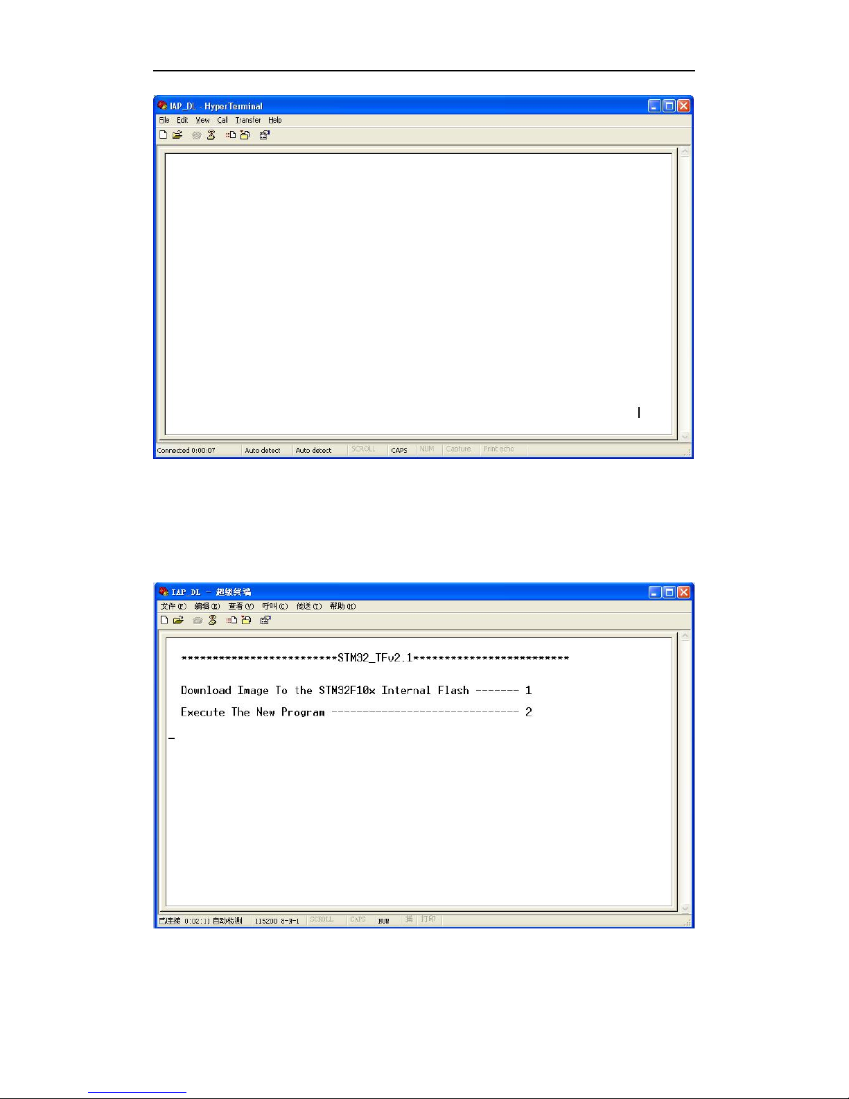
15
7) Turn Off RD05 device
①
Connect BT_S and GND and Turn on Power , Device all indicator will keep
light at same time, (all of the device’s indicator will be keep light for a
moment)Hyper terminal will display the interface like the picture follow
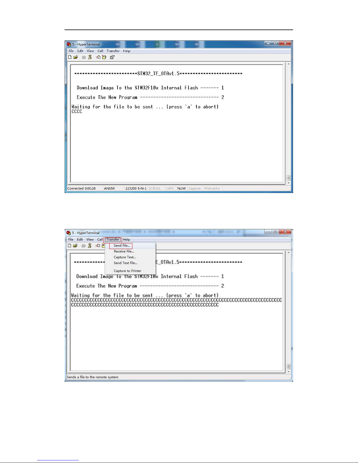
②
Press Keypad 1, Hyper terminal will display( waiting for the file to be
sent ...CCCCC).
Page 16
16
③
Then choose Send file(Send-> Send File) at soon as possible, because the
update mode will keep for 92 seconds, if out of this time update will not be
process succeed.
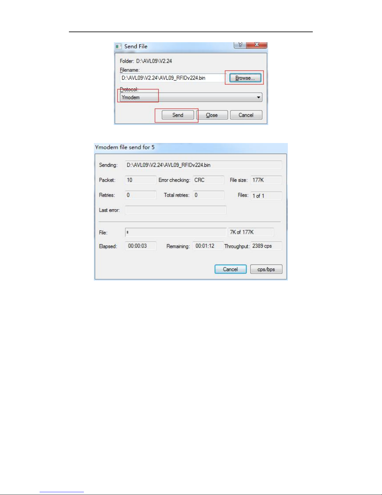
8) Choose the firmware that you want to Update
;
Protocol Choose: Ymodem
Page 17
17
9) Press Send button, Will display a New Windows that show the update process.
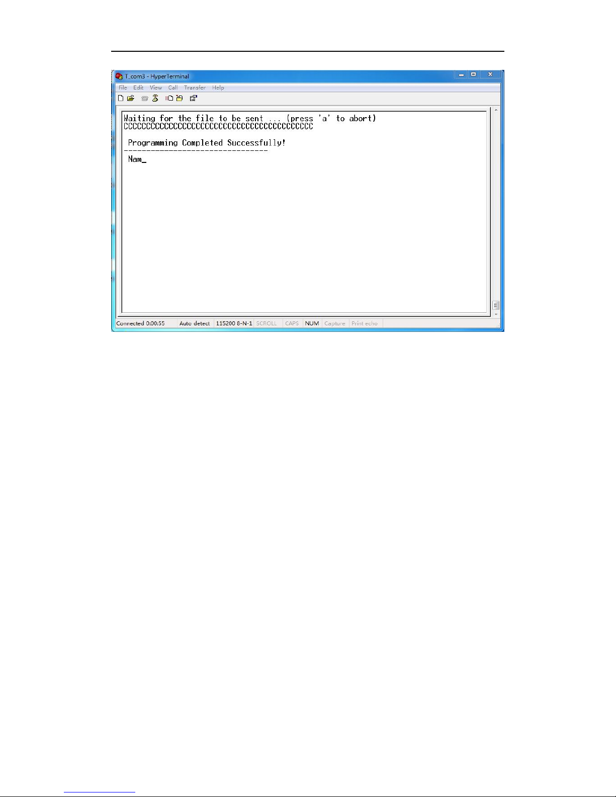
10) When finish update, will appear "Programming Completed Successfully!",
then press Keypad 2.
Page 18
18
11) Turn On RD05 again.(at this times the firmware will load the parameter to
the unit ). Then the firmware updates finished.
 Loading...