

TYVA MODULOO, PCB 4S, PCB 2P, PCB 8S, PCB 1P Assembly Manual

Assembly manual
TYVA MODULOO
UK 3.0
Versions : 1S/8P-4S/2P-8S/1P

SUMMARY
1 PRECAUTIONS AND SAFETY MESURES
2.0 MODULES AND ACCESORIES TYVA MODULOO
2.1 MODULOO HOUSING DETAILS
2.2 PCB SETTING IN HOUSING
2.3 VERSIONS OF LIDS
2.4 ELECTRICAL SPECIFICATIONS OF VARIOUS PCB
2.4.1 PCB 4S/2P (12,8 to 14,8 V)
2.4.2 PCB 8S/1P (25,6 to 29,6 V)
3.1 COVER SETTING UP
3.2 Li-ion 18650 CELLS
3.3 HOUSING POSITIONING
3.4 18650 CELLS SETTING UP
3.5 THE ESTABLISHMENT OF THE SPACERS
4 ASSEMBLY NEGATIVE COVER
5 SCREWING COVER SCREW M3 ON NEGATIVE
6 POSITIVE COVER MOUTING
7 POSITIVE COVER MOUTING
8 SCREWING COVER SCREW M3 ON POSITIVE
9 POSITIVE AND NEGATIVE COVER ASSEMBLY 4S-2P et 8S-1P
Manual UK 2.0
Read the manual before integration of 18650 cells into the modules
Before making the connections, make a freehand sketches defining all electrical connections
Remove all metal objects from your hands : ring ,bracelet, watch…etc.
Use insulated tools
Do not short-circuit the modules
Do not immerse the modules in wetlands
Do not immerse into liquids modules
Do not burn the modules
Do not disassemble the modules
Do not subject modules to shocks or falls
Use a suitable battery charger (voltage and load current)
Use only accessories and screws supplied with TYVA MODULOO modules
For higher voltages up to 48 volts, use personal protective equipment, gloves, goggles and face shield, hearing
protection.
Do not integrated into the modules of 18650 cells of different batches, voltage and chemistry
1 PRECAUTIONS AND SAFETY MESURES
Manuel UK 2.0
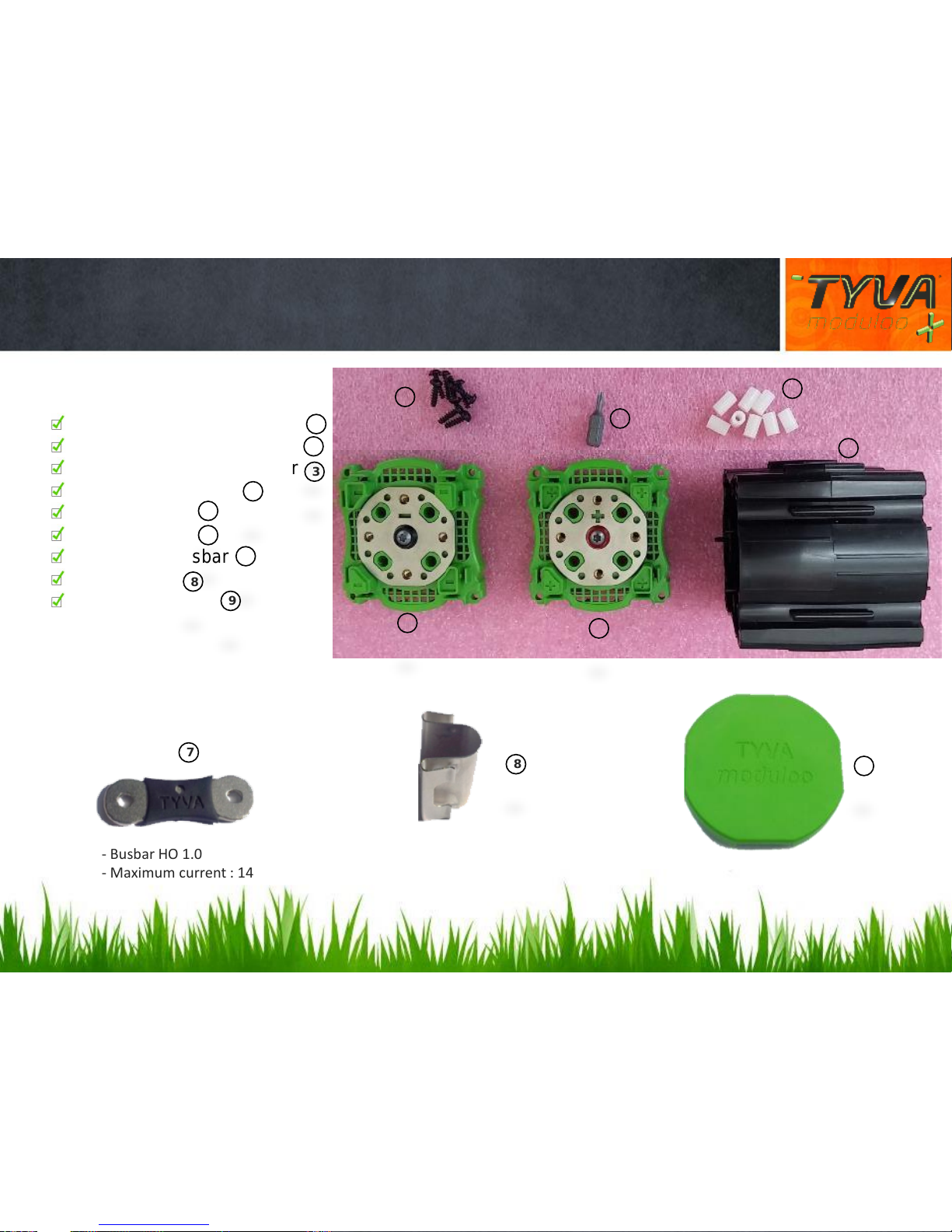
2.0 TYVA MODULOO MODULES AND ACCESSORIES
6
5
4
1
8
7
9
1
3
2
Housing TYVA MODULOO
Assembled positive cover
Assembled negative cover
T10 M3x14 screws
Mounting tool
Cells spacers
Horizontal Busbar
Vertical clip
Protective cover
4
8
9
7
3
2
1
5
6
- Busbar HO 1.0
- Maximum current : 140 A
- Busbar VE 1.0
- Maximum current: 30 A
Manuel UK 2.0
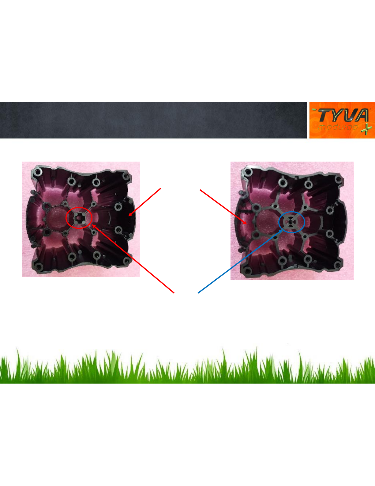
2.1 MODULOO CASES DETAILS
POSITIVE LID
NEGATIVE LID
Landmarks
Slots available for
PCM ou BMS
Manual UK 2.0

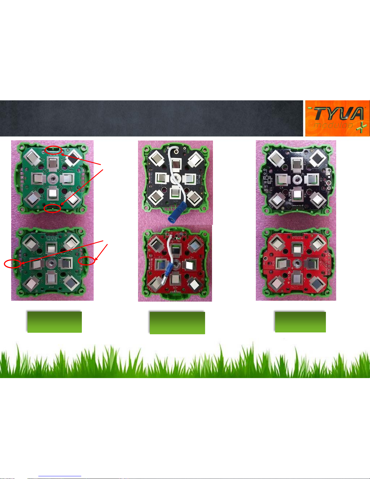
2.2 FIXING THE PCB IN THE HOUSING
POSITIVE LID
NEGATIVE LID
Fixing holes
Optional fixing holes for power PCB range
Manual UK 2.0
2.3 VERSIONS OF LIDS
Positive lid
Negative
hole
Pins
Pins
Positive lid
Positive lid
Positive lid
Negative lid
Version 1S/8P
(3,2 to 3,6 V )
Version 4S/2P
(12,8 to 14,8 V )
Version 8S/1P
(25,6 to 29,6 V )
Manual UK 2.0
 Loading...