

Page 1

TO CUSTOMERS
Thank you very much for using our two way radio.
This radio of modern design is reasonable structure
with stable functions. It is designed to meet different
customers' need for high quality with easy operation
and perfect capablity. We believe you are pleased
with its nice shape and excellent performance.
This manual is suitable for using the model
of UV8000E.
Page 2

Welcome to use two-way radio
http://www.tyt888.com
Dual band, dual display, dual standby
2*128 channels to store
FM radio receiver and 25 channels
Channel spacing selectable(25/12.5kHz)
Hand free VOX function
CTCSS/DCS encoding and decoding
Cross band function
Low battery alarm
Emergency Alarm
Shift repeater function
ANI function
DTMF &Remote kill/stun function
Reverse frequency function
Tri-color background light selectable
Chinese & English prompt
MSK
1750 Tone
Main Functions
Page 3

Contents
Using tips
Unpacking and checking equipments
Battery
Antenna
Installing and Uninstalling of supplied accessories
Getting familiar
Working mode
Detailed Function Descriptions
Basic Operations
Optional Accessories
Trouble shooting guide
Specifications
Warranty card
01
02
04
07
08
13
18
27
35
46
47
48
User's Manual
Using tips
Unpacking and checking equipments
http://www.tyt888.com
Page 4
01
Using tips
Please read the following brief instructions, non-compliance with these rules may cause
danger or violate the law.
Obey the local government regulation before using this radio, improper use may violate
the law and be punished.
Turn off the radio before entering flammable or explosive areas.
Do not charge or change the battery in flammable or explosive areas.
Turn off the radio before getting close to the blasting zone or detonator areas.
Do not use radio whose antenna is damaged, touching of damaged antenna will cause
heat injury.
Do not attempt to open the radio; the maintenance work should be done by technical
expert only.
To avoid troubles caused by electromagnetic interference or electromagnetic
compatibility, please turn off the radio in places where have the banner "Do not use
wireless equipment", such as hospital and other healthcare places.
In the car with an airbag, do not put the radio within the scope of the airbag deployment.
Do not store the radio under the direct sunshine or in hot areas.
When you transmit with the radio, do keep away from its antenna for 5cm at least.
If the radio appears smelly or smoke, please shut off its power immediately and contact
with your local dealer.
Do not transmit too long, for the radio may heat and hurt the user.
02
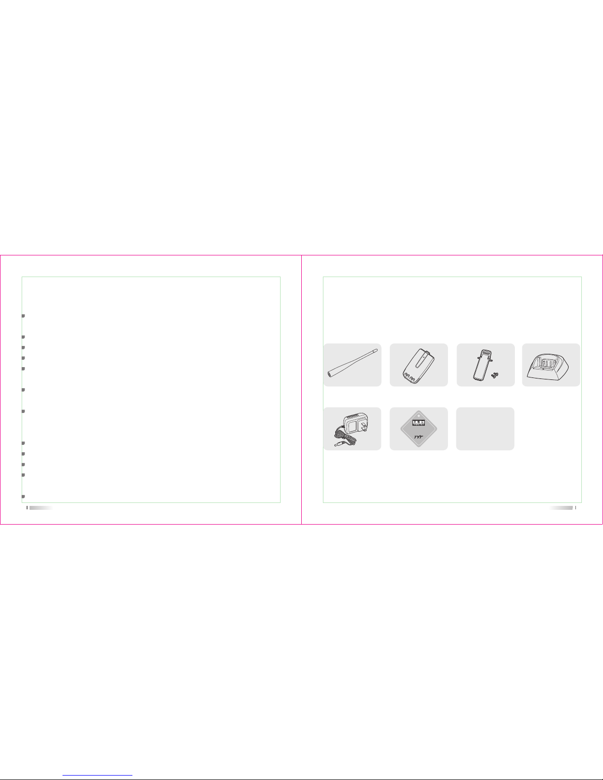
Note: The antenna frequency range please refers to the annular label at the bottom of antenna.
Antenna (1) Li-ion battery (1)
Verification (1)
Belt Clip (1) Charger (1)
Charger
Adapter (1)
User's Manual (1)
Supplied accessories:
Unpacking and checking equipments
Carefully unpack the radio. We recommend you check the items listed in the following
table before discarding the package. If any item is missing or has been damaged during
shipment, please contact us immediately.
***********
TYT Science & Technology Electron Co., Ltd.
Page 5

User's Manual
Battery
Antenna
Installing and Uninstalling of supplied accessories
http://www.tyt888.com
04
Battery
Please use designated battery; other batteries can cause explosion and hurt people.
Notice: 1. Please do not short-circuit the battery terminals or expose of in fire. Do not dissemble
the battery by yourself.
2. Charge the battery between temperature 0* and 45*. The battery can not be fully
charged beyond this temperature range.
3. Please turn off the power when you charge the radio with battery. Transmit with the
radio in charge will affect its correct charge.
4. Do not unplug the power or battery when it is charged.
5. The operating time becomes short even the battery is fully charged, the battery is
exhausted, please replace battery.
6. Please do not charge when the battery or the radio is wet. Please dry it with a cloth
before charging to avoid any danger.
Warning: When the conductive metals such as jewelery, key or decorative chains touch the
battery terminals, all the batteries are likely to cause damage to the items or personal
injury. These conductive metals may form a short circuit and generates much heat.
Do deal with any battery carefully, especially when put it into pocket, wallet or other
metallic containers.
Page 6

05
Charge the battery as follows:
1) Power off
2) Insert the DC adaptor plug in the DC jack on the back of charger
3) Insert the AC adaptor plug in the AC power output socket
4) Insert the battery or radio with battery vertically in a charger, to check whether the
battery and charger terminal is in normal contact.
5) Make sure the battery and charger terminal is in good contact, when the charging
indicator light turns red, it starts charging.
Charging operations:
Note: 1. Before inserting the battery, it is abnormal if the charging indicator blinks
2. To change the battery for charging, please wait until the indicator is stable.
3. When the battery is well inserted, the indicator turns red and the charging is on the
process, if the indicator blinks, then the battery is damaged or the temperature is too
high or too low.
When the charger powers up, if the orange indicator lights for one second and then goes
out, entering the standby mode, the charger passes the self-testing and can charge the
battery. If the orange indicator blinks constantly, the charger fails to pass the self-testing,
and can not charge the battery.
Self-testing
06
When charging the battery, if the indicator light turns red, the battery is on the normal
charge; if the red indicator light blinks constantly, the battery capacity is too low, and is on
the trickling charge, and after the battery capacity reaches a certain level, it will switch to
the normal charge.
Normal charging indicator
Note: Trickling charge does not exceed 30 minutes, if the red indicator light blinks after 30
minutes, it means the charger can not charge battery, please check whether the battery
or the charger has been damaged.
1) The battery is not fully charged in factory, please charge before using it.
2) Charge and discharge the battery for two or three times, the battery capacity will reach
the best condition. When the battery capacity is low, please charge or change the battery.
3) The battery lasts shortly even if it is fully charged, the battery is exhausted, please
contact your local dealer to buy a new authentic TYT battery.
Charging precautions:
Page 7

07
Antenna
Short thick antenna is suitable for short-distance communication, while long thin antenna
will offer you a better communication effect. Wearing the radio in your waist will not make
you feel uncomfortable.
The communication range will be shortened in bad weather or among the trees, please
prepare in advance to avoid any inconvenience of your communication and security.
08
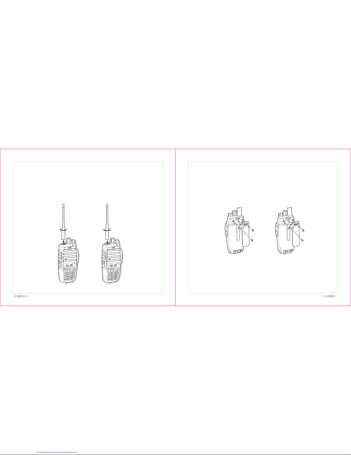
Installing and uninstalling of the accessories
1) Align the two grooves of battery and the guide rail on the back of aluminum shell,
ensuring full contact and in parallel, then push the battery up to the radio base along
the rail on the back of aluminum shell, until the battery latch locks up. (picture 1)
2) To remove the battery, please make sure the radio is closed, push the battery latch
down, and make sure the radio and battery is on the releasing state, and then push
the battery out from the radio. (picture 2)
Installing/Removing the battery
(picture 1) (picture 2)
Page 8
09
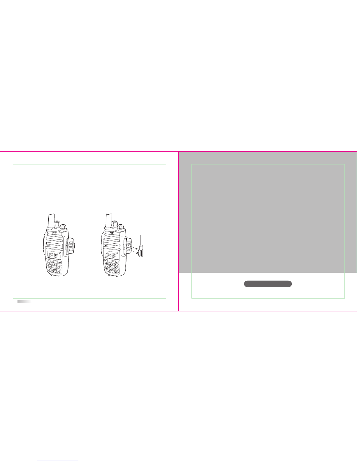
1) Align the threaded end of antenna and the threaded hole at the top of radio, rotate the
antenna clockwise until it is tight. (picture 3)
2) To remove the antenna, rotate it counter-clockwise until the antenna spirals out.
(picture 4)
Installing and removing the antenna
(picture 4)(picture 3)
10
(picture 5) (picture 6)
1) Align the two holes of belt clip and the two holes of the radio, fix them with the supplied
M2.5x5 screw. (picture 5)
2) Loosen the screw set to remove the belt clip (picture 6)
Installing/removing the belt clip
Page 9
Getting familiar
User's Manual
http://www.tyt888.com
11
Reveal (do not remove) the mic/speaker jack cover (picture 7), insert the headset into the
mic/speaker jack (picture 8).
Note: Using the external headset will affect the water-tightness performance of radio.
Installing external headset
(picture 8)(picture 7)
Page 10
Getting familiar
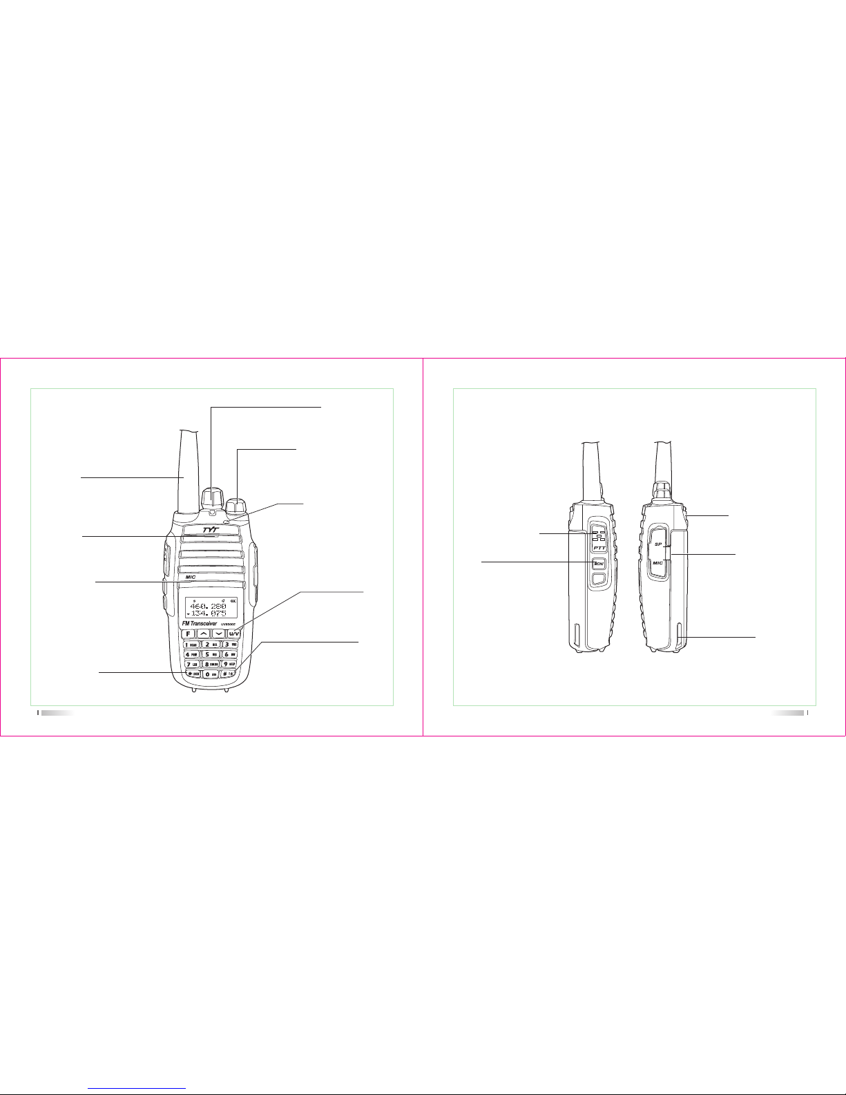
LED indicator light
The indicator light turns red
when transmit, turns green
when receive.
It blinks red when the battery
capacity is low, and blinks green
when scanning.
Microphone
sound input
Antenna
connect the supplied antenna here.
13
Long press this key can lock
or unlock the keypad under
standby mode.
Lock
Using to adjusting the
channel and frequency
Channel Knob
Power/Volume Knob
this control toggle the transceiver's
power on/off and adjust the volume
level.
Speaker
the internal speaker
is located here.
this key can be used to
shift the band A/B, and
exited the Function Menu.
U/V
Short press this key under standby
mode can shift the VFO Mode and
MR mode, long press this key can
exchange of RX frequency and TX
frequency
#T-R
14
Mic/speaker jack/
programming port
Belt clip
You can clip the radio in the
belt and is easy to take.
Used to connect headset or
external programming cable.
Programmable via PC
programming software.
Li-ion battery
For charging the radio.
press it to transmit and
release it to receive after
your transmission is completed.
PTT
Press and hold this key
disables the noise squelching
action ,allowing you to hear
very weak signals near the
back-ground noise level.
MONI
Page 11

LCD DISPLAY
You will see various icons shown on the screen when power on. The following table can
help you identify icons’ meaning which display on LCD.
Description of functions
Operating band signal & power meter
Low TX power active
Dual watch/standby active
RX power save active
VOX active
Repeater shift direction
Reverses the transmit and receive frequency active
Narrow band mode active
Keypad lock active
Icons
15 16
Description of functions
Squelch active
Beep tone active
Receive calling ID or MSG
Scrambler active
Battery power indicator
Set CTCSS tone
Set DCS code
DTMF signaling active
Operating A band indicator
Operating B band indicator
Frequency mantissa indicator
Channel number/Menu items number indicator
Busy channel indicator
Channel scanned available under CH mode
Icons
Page 12

User's Manual
http://www.tyt888.com
Working mode
18
Channel Mode(CH)
When you have stored a memory channel at least, it can work in CH mode, Channel NO,
will be indicated on the display. Press , then turn on the radio, it will enter CH mode,
Press , then turn on the radio, it will exit CH mode.
Frequency Mode(VFO)
Under this mode, you can use key to change the frequency, then press or , or
the channel knob or input the frequency by keypad directly and store channel.
Working mode
Frequency Channel (MR) Mode
When you have stored a memory channel at least and under VFO mode, press key to
enter MR mode.
The frequency will be indicated on the display and the channel No. will be indicated at the
right side. If the transceiver display name option is ON and the channel name edited, it will
show the name of the channel.
Page 13
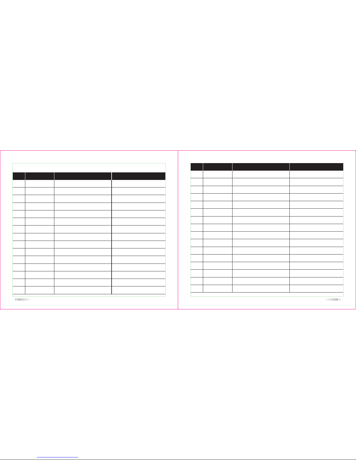
19
01
SCAN Frequency/Channel Scan
No. LCD Display Description of FunctionAvailable Values
/
SQL level setting
Dual Wait/Standby
LED Display mode
Background Light Color
Keypad Beeper Setting
Automatic Number Identity
Repeater frequency setting
ID
Code
Transmitter Time-Out Timer
OFF / WAVE / CALL
0-9
ON / OFF
ON / AUTO / OFF
COLOR1 / COLOR2 / COLOR3
ON / OFF
ON / OFF
ON/OFF
0-9
BOT/EOT/BOTH/OFF
OFF/30/60/....../360
OFF / WAVE / CALL
SQL
D.WAIT
LED
LIGHT
BEEP
ANI
Turn
ID
PTT ID
TOT
BCLO
05
06
07
08
09
10
11
12
13
14
15
04 POWER High/Low TX PowerLOW / HIGH
03 VOX VOX Level Setting1-8
02 TX.SEL Priority TransmitEDIT / BUSY
SET MENU MODE
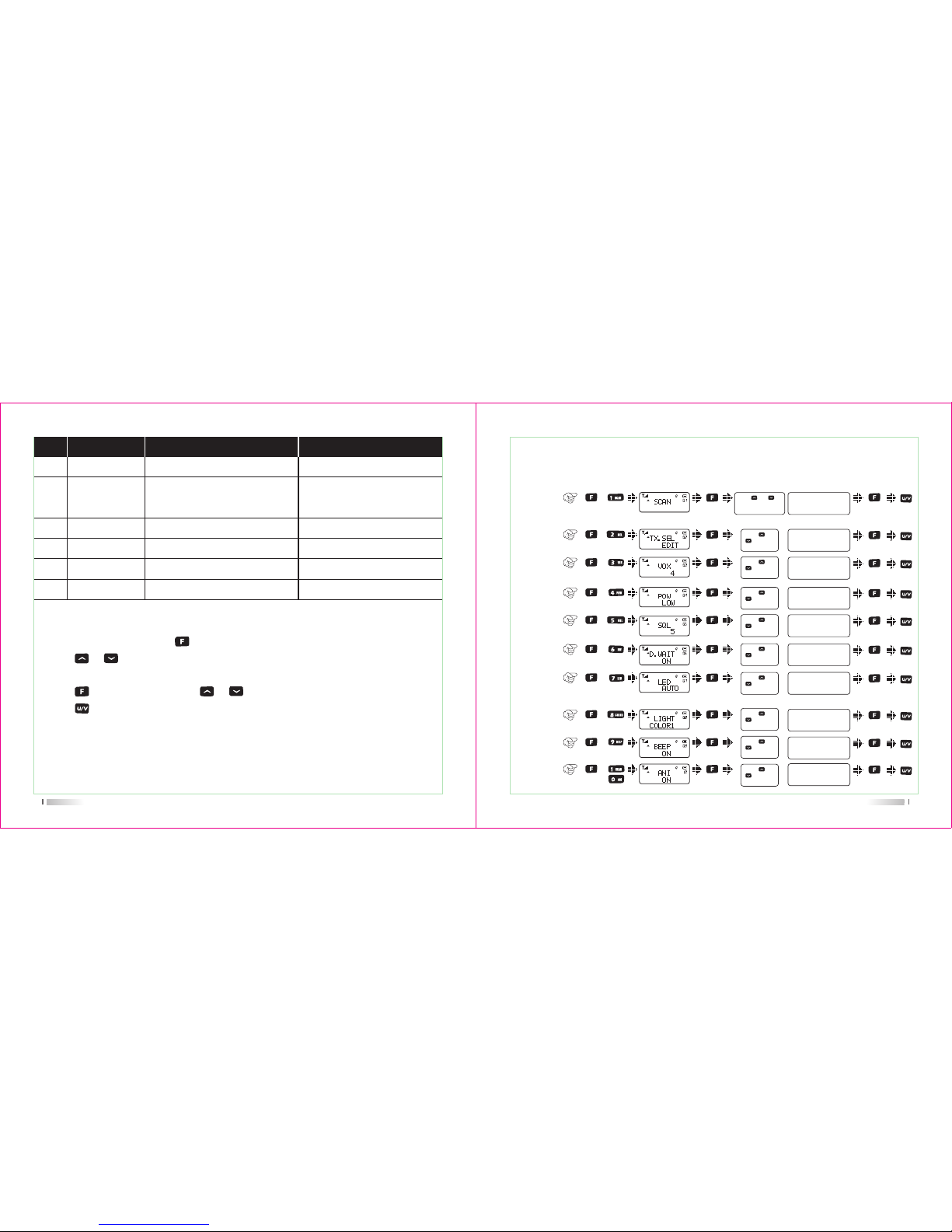
20
No. LCD Display Description of FunctionAvailable Values
VOX Switch ON/OFF
Transmit Over Beeper
Dual Watch/Monitor
Receive Saver
Scan Mode
Auto Keypad Lock
Voice Prompt
End-tone elimination
Power-on Display
Battery Power Voltage
Power-on Message
Display channel name
Channel Name Editing
TX/RX Tone coder
RX Tone coder
TX Tone coder
ON / OFF
ON / OFF
ON / OFF
ON / OFF
TO / CO / SE
ON / OFF
ON / OFF
ON/OFF
OFF / DC / MSG
/
-1A, @
ON/OFF
-1A, @
OFF / 67.0 / D023N
OFF / 67.0 / D023N
OFF / 67.0 / D023N
VOX.SW
ROGER
DW
RX.SAV
SCAN.S
AUTOLK
VOICE
TALK
OPNSET
VTL
MSGSET
DIS.NM
CHNAME
C-CDC
R-CDC
T-CDC
16
17
18
19
20
21
22
23
24
25
26
27
28
29
30
31
Page 14
21
No. LCD Display Description of FunctionAvailable Values
Shift Direction
Repeater Shift
(Under VFO mode)
VFO Step
Select Channel Spacing
CTCSS Scanning
DCS Scanning
+ / - / OFF
2.5K / 5K / 6.25K / ... / 25K
WIDE/NARROW
/
/
S-D
STEP
N/W
SEEK 67.0
SEEK D023N
32
34
35
36
37
OFFSET 0.000-99.995MHz33
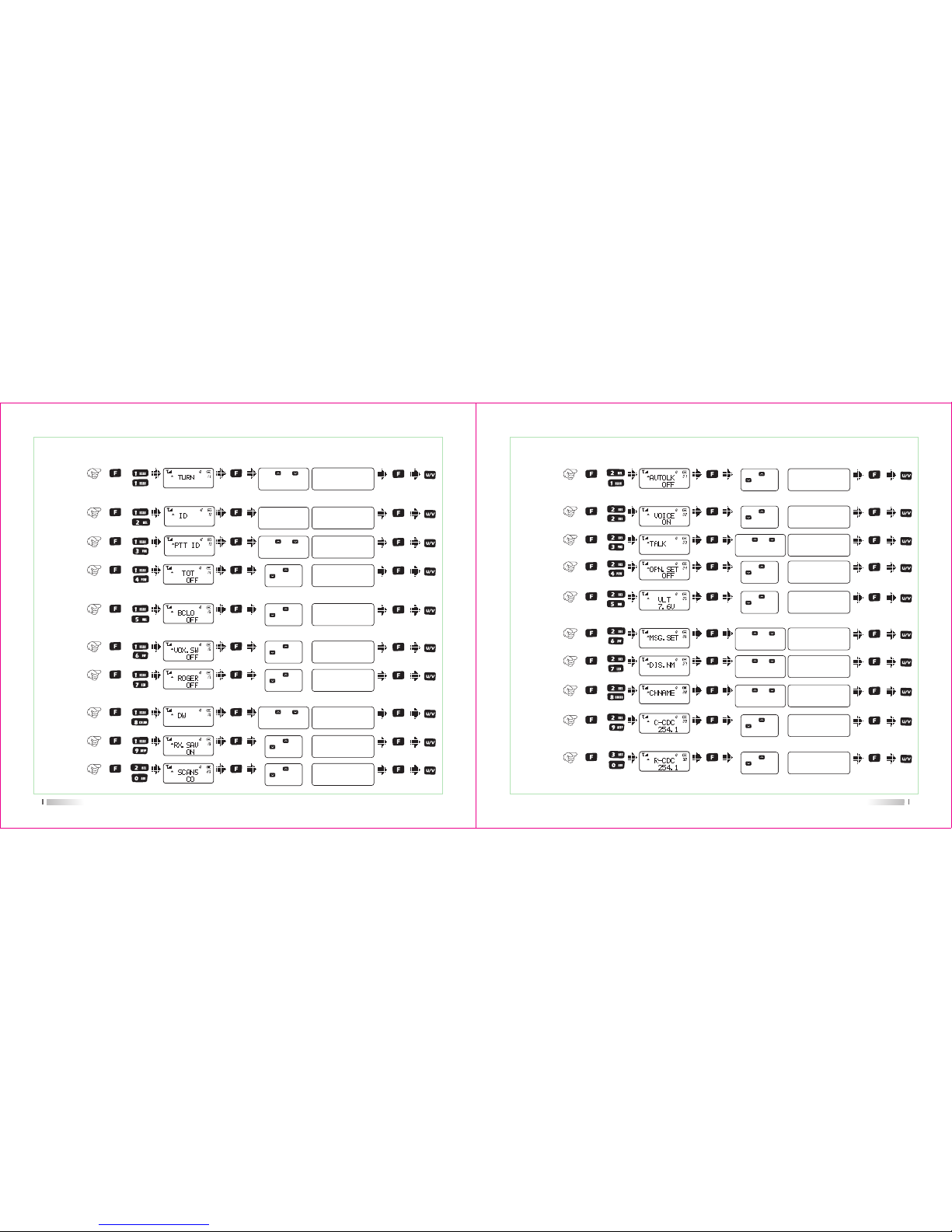
Menu Operation
1) Under standby mode, press to enter menu setting, LCD displays "MENU"
2) Press or , or rotate the channel knob to select the desired menu item, LCD display
current setting of selected item.
3) Press to enter and then press or to select the desired setting.
4) Press to exit and return to the standby mode.
Item
No.
Item
Name
Enter
item
Screen
Display
Parameter
Explanation
Confirm Return
Standby
Select
parameter
Frequency
/Channel
scan
1)
+
Priority
Transmit
2)
+
+
+
SQL level
setting
5)
+
Dual wait/
standby
6)
+
LED
display
mode
7)
+
Background
light color
8)
+
Keypad
beeper
9)
+
+
Automatic
Number
Identity
10)
22
SHORTCUS MENU OPERATION
PTT/MONI/U/V
Press [ ] or [ ] or
rotate the channel knob
to change the frequency
VOX level
setting
3)
TX power
setting
4)
Press [ ] or
[ ] to select
available values
Press [ ] or
[ ] to select
available values
Press [ ] or
[ ] to select
available values
Press [ ] or
[ ] to select
available values
Press [ ] or
[ ] to select
available values
Press [ ] or
[ ] to select
available values
Press [ ] or
[ ] to select
available values
Press [ ] or
[ ] to select
available values
Press [ ] or
[ ] to select
available values
VOX level: 1~9
High / Low
SQL level: 0~9
ON / OFF
ON / AUTO / OFF
1/2/3
ON / OFF
ON / OFF
EDIT / BUSY
Page 15
Item
No.
Item
Name
Enter
item
Screen
Display
Parameter
Explanation
Confirm Return
Standby
Select
parameter
+
11)
ON / OFF
+
12)
+
13)
VOX
switch
16)
Transmit
over
beeper
17)
ON / OFF
ON / OFF
+
Transmitter
time-out
timer
14)
Busy
channel
lock-out
15)
OFF/WAVE/CALL
18)
ON / OFF
+
Receive
saver
19)
ON / OFF
+
23
Repeater
frequency
setting
ID
input 0-9
F to confirm,
*lock to delete
PTT ID
BOT/EOT/BOTH/
OFF
Press [ ] or
[ ] to select
available values
OFF / 30... / 270s
+
Press [ ] or
[ ] to select
available values
+
Press [ ] or
[ ] to select
available values
+
Press [ ] or
[ ] to select
available values
Monitor
Press [ ] or [ ]
OR channel knob to
select available values
Press [ ] or [ ] or
rotate the channel knob
to change the frequency
+
Press [ ] or
[ ] to select
available values
Scan
mode
20)
TO / CO / SE
Press [ ] or
[ ] to select
available values
Press [ ] or [ ]or
rotate the channel knob
to change the frequency
Item
No.
Item
Name
Enter
item
Screen
Display
Parameter
Explanation
Confirm Return
Standby
Select
parameter
+
Auto
keypad
lock
21)
ON / OFF
Voice
prompt
22)
ON / OFF
+
23)
ON / OFF
+
26)
+
Battery
power
voltage
25)
Show current
voltage
27)
+
28)
+
+
24
Press [ ] or
[ ] to select
available values
Press [ ] or
[ ] to select
available values
Press [ ] or [ ]or
rotate the channel knob
to change the frequency
End-tone
elimination
Power-on
display
24)
OFF / DC / MSG
+
Press [ ] or
[ ] to select
available values
+
Press [ ] or
[ ] to select
available values
Press [ ] or [ ]or
rotate the channel knob
to change the frequency
MSG
setting
*LOCK/#T-R/U/V
Press [ ] or [ ]or
rotate the channel knob
to change the frequency
Display
the name
ON/OFF
Press [ ] or [ ]or
rotate the channel knob
to change the frequency
Channel
Name
*LOCK/#T-R/U/V
TX/RX
tone
coder
29)
OFF / QT / DCS
+
Press [ ] or
[ ] to select
available values
OFF / QT / DCS
RX tone
coder
30)
Press [ ] or
[ ] to select
available values
Page 16
Item
No.
Item
Name
Enter
item
Screen
Display
Parameter
Explanation
Confirm Return
Standby
Select
parameter
+
+
+
0.000-99.9975MHz
+
+
+
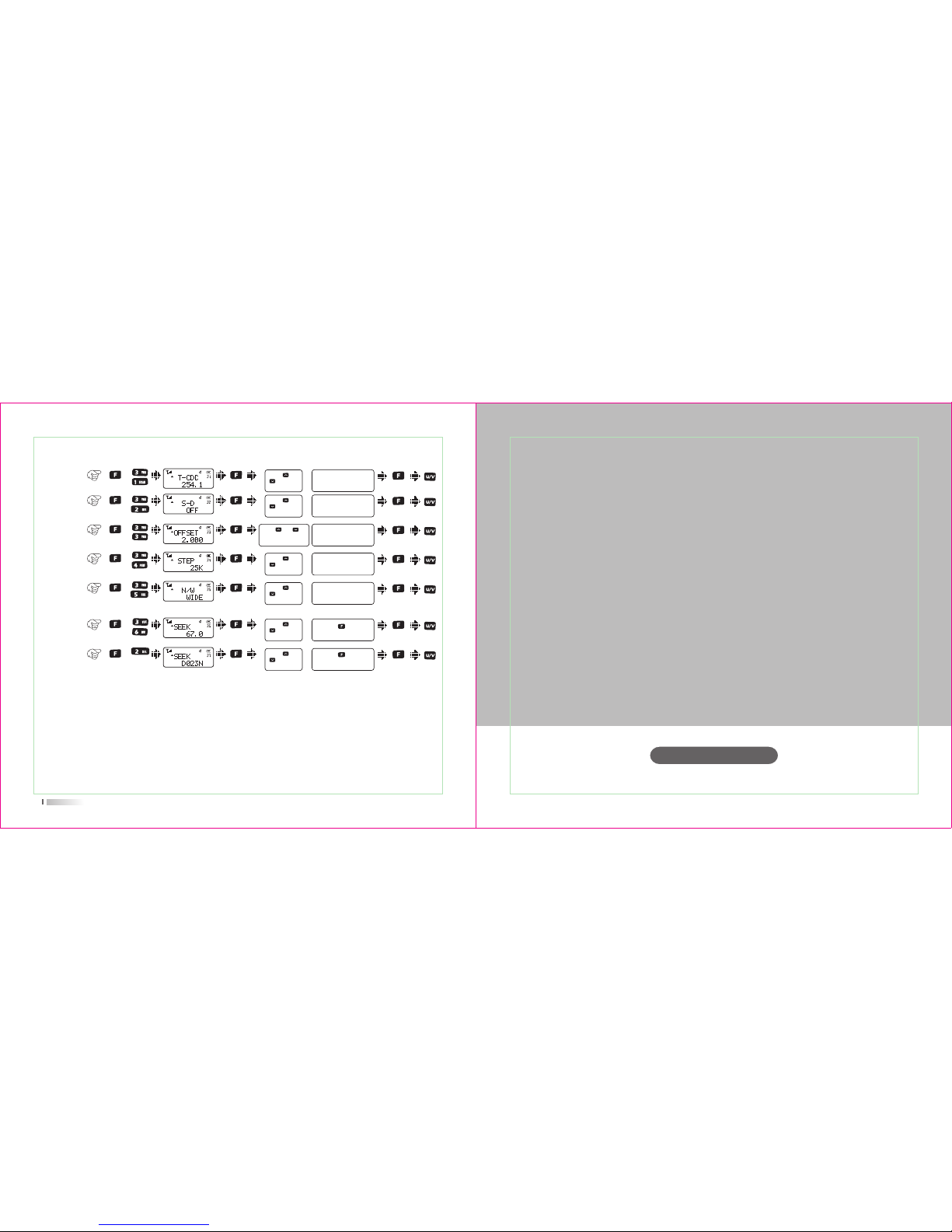
25
Press [ ] or
[ ] to select
available values
TX tone
coder
31)
OFF / QT / DCS
Press [ ] or
[ ] to select
available values
Shift
direction
32)
+ / -
Press [ ] or
[ ] to select
available values
Repeater
Shift
33)
Press [ ] or [ ]or
rotate the channel knob
to change the frequency
VFO step34)
2.5K / 5K / 6.25K /
10K...100K
Press [ ] or
[ ] to select
available values
Wide/
Narrow
band
35)
Wide/Narrow
CTCSS
scan
36)
Press [ ] key to
start scan
Press [ ] or
[ ] to select
available values
DCS
scan
37)
Press [ ] key to
start scan
+
Press [ ] or
[ ] to select
available values
User's Manual
http://www.tyt888.com
Detailed Function Descriptions
Basic Operations
Page 17

28
2) Priority Transmit (TX.SEL---MENU 2)
Functions: UV8000E allows you to transmit on the sub band even if you are working
on the operating band.
Enter Menu 2
nd
to select priority transmit band. Default: EDIT.
EDIT: It will transmit on the operating band.
BUSY: It will transmit on the band last talking used.
3) VOX Level & VOX Switch (VOX&VOX.SW---MENU 3&16)
Functions: the VOX function provides automatic transmit/receive switching based on
voice input to the microphone. With the VOX switch ON, you do not need to
press PTT switch in order to transmit, and it is not necessary to use a VOX
headset in order to utilize VOX operation.
Enter Menu 16
th
to set VOX switch. Default: OFF.
When the VOX is activated, the “VOX” icon will appear on the display.
Enter Menu 3
rd
to set VOX level. It has 9 grades.
The higher level is, the more sensitive will be.
UV8000E
provides for adjustment of “Hang-Time” of the VOX (the transmit-receive
delay after the cessation of speech) via program software.
Default: 2s.
4) TX Power setting (POW---MENU 4)
Functions: you can select high/low TX power according to your talking environment
and need. When you store memories, you can store High and Low power
DETAILED FUNCTION DESCRIPTIONS
1) Scan & Scan Mode setting (SCAN&SCANS---MENU 1&20)
Functions: under VFO/MR/CH mode, TH-UV8000D allows you to scan the entire current
operating band and memory channels.
Enter Menu 1st and press [ ] key to start scanning.
When you have started scanning, press [ ] / [ ] key to change direction. And it
will halt on a signal it encounters, press PTT key to stop scanning; Press MONI key to
stop scanning temporarily; Press [ ] key again to exit the scanning function.
Scanning operation is basically the same in each of the above modes. Before you begin,
take a moment to select the way in which you would like the scanner to halt on a signal.
Enter Menu 20
th
to set scan mode. Default: TO.
Three options for the scan mode are available under VFO mode:
TO: In this mode, the scanner will halt on a signal it encounters, and will hold there for
some time. If you do not take action to disable the scanner within the time period,
the scanner will resume even if the stations are still active.
CO: In this mode, the scanner will halt on a signal it encounters, and will hold there if
the stations are still active. And after the carrier has dropped, the scanner will
resume.
SE: In this mode, the scanner will halt on a signal it encounter, it will not restart
automatically; you must manually re-initiate scanning if you wish to resume.
27
Page 18

29
5) Squelch Adjustment (SQL---MENU 5)
Functions:
UV8000E
’s Squelch system allows you to mute the background noise
when no signal is being received. Not only does the Squelch system “stan-
dby” operation more pleasant, it also significantly reduces battery current
consumption.
Enter Menu 5
th
to set SQL level. Default: 5.
6) Dual Wait/Standby (D.WAIT---MENU 6)
Functions:
UV8000E Rallows you to receive the sub band signal even if you are working
on the operating band. It could monitor the signal under both master and
sub band at the same time.
Enter Menu 6
th
to set Dual Wait. Default: ON.
settings separately in each memory.
Enter Menu 4
th
to set TX power.
High: 10W
Low: 5W, when you select Low power, the “L’ icon will appear on the display.
7) LED Display Mode (LED---MENU 7)
Function: select the LED/Keypad Lamp mode.
Enter Menu 7
th
to select LED display mode. Default: AUTO.
ON: LED display lights all the time.
AUTO: Illuminates the LED when any key is pressed and after 3s the light is off.
30
OFF: Disable the LED lamp.
8) Background Light Color (LIGHT---MENU 8)
Functions: choose LED background light color.
Enter Menu 8th to select background light color. Default: Default1.
1: Purple.
2: Orange.
3: Blue.
9) Keypad Beeper setting (BEEP---MENU 9)
Functions: enable/disable the keypad beeper.
Enter Menu 9
th
to set keypad beeper. Default: ON.
10) Automatic Number Identity (ANI---MENU 10)
Functions:
sending ID code when UV8000E transmits, the others can receive it directly
on the display if they also have ANI function.
Enter Menu 10
th
to set ANI. Default: OFF.
11) Repeater frequency setting
Enter Menu 11th to turn on/off the setting.
12 ) ID setting
13) PTT ID setting
Enter Menu 12th to set the ID number.
Enter Menu 13th to set the PTT ID
Page 19

15) Busy Channel Lock-Out (BCLO---MENU 15)
Functions: the BCLO feature prevents the radio’s transmitter from being activated if a
signal strong enough to break through the “noise” squelch is present. On a
frequency where stations using different CTCSS or DCS codes may be
active, BCLO prevents you from disrupting their communications
accidentally (because your radio may be muted by its own tone decoder).
Enter Menu 15th to set BCLO. Default: OFF.
OFF: Disable BCLO feature.
WAVE: the radio’s PTT will be prevented only if the frequency is busy used.
CALL: the radio’s PTT will be prevented only the frequency and tone coder is the same.
31
14) Transmitter Time-Out Timer (TOT---MENU 14)
Functions: the TOT feature provides a safety switch which limits transmission to a
pre-programmed value. This will promote battery conservation by not
allowing you to make excessively-long transmissions, and in the event of
a stuck PTT switch it can prevent interference to other users as well as
battery depletion.
Enter Menu 14th to set TOT. Default: OFF.
16) VOX Switch
Enter Menu 16th to switch on /off the Vox function.
21) Auto Keypad Lock (AUTOLK---MENU 21)
Functions: in order to prevent accidental frequency change or inadvertent transmission,
various aspects of the
TH-UV8000D
’s keys and switches may be locked out.
Enter Menu 21th to set AUTOLK. Default: OFF.
When you switch AUTOLK ON, the keypad will be locked automatically if there is no key
operation for 5 second.
If the radio is locked, press [ ] key to unlock it. Also you can lock it using [ ] key
32
receive the full data burst.
Enter Menu 19th to set RX.SAV. Default: OFF.
19) Receive Saver (RX.SAV---MENU 19)
Functions: this feature significantly reduces quiescent battery drain, and you may not
18) Dual Watch/Monitor (DW---MENU 18)
Functions: Dual Watch feature makes
TH-UV8000D
can monitor the calling signal when
FM radio is on and you won’t miss any calling.
Enter Menu 18th to set DW. Default: OFF.
17) Transmit Over Beeper (ROGER---MENU 17)
Functions: sending a beeper to inform the receiver TX is over.
Enter Menu 17th to set ROGER. Default: OFF.
20) Scan Mode Setting
Enter Menu 20th to set the scan mode.
Page 20

33
22) Voice Prompt (VOICE---MENU 22)
Functions: enable/disable voice prompt.
Enter Menu 22th to set VOICE.
by manual.
24) Power-on Display setting (OPN.SET&VLT&MSG.SET---MENU 24&25&26)
Functions: choose power-on display mode and edit power-on message
Enter Menu 24th to set OPN.SET. Default: OFF.
OFF: display model version
DC: battery power voltage
MSG: power-on message
Enter Menu 25st to check battery voltage.
Enter Menu 26nd to edit power-on message, also you can edit it directly by
23) End-tone elimination
Enter Menu 23th to switch on/off the tail elimination function
25) Display the name (DIS.NM&CH.NAME)
Functions: switch channel name display mode ON/OFF and edit channel name under
MR/CH mode .
26) Tone coder & Tone Search Scanning & Tone calling (C-CDC& R-CDC&
T-CDC
Function 1: CTCSS/DCS Operation
34
If the Tone scan feature does not detect a tone or code, it will continue to scan
indefinitely. When this happens, it may be that the other station is not sending any tone.
You can press PTT key to halt the scan at any time.
You also can press MONI key during Tone scanning to listen to the (muted) signal from
the other station. When you release the MONI key, Tone scanning will resume.
Tone Scanning works either in the VFO or MR modes.
Operation: Press + to enter the CTCSS setting, Press to confirm, then
press to enter 32nd Menu.
OFF: Disable the CTCSS/DCS.
67.0: the CTCSS number.
D023N: DCS number.
Many repeater systems require that a very-low-frequency audio tone be superimposed
on your FM carrier in order to activate the repeater. This helps prevent false activation
of the repeater by radar or spurious signals from other transmitters.
Enter Menu 29th/30th/31th to set TX&RX Tone coder/ RX Tone coder/ TX Tone coder.
27) Offset frequency and direction setting(S-D&OFFSET--MENU 32 & 33)
Functions: Under VFO mode, you can set the offset frequency and direction to connect
with repeater.
Enter Menu 32nd to set offset direction.
Default: OFF
Enter Menu 33rd to set offset frequency.
Page 21

35
28) VFO Step setting (STEP---MENU 34)
Functions: setting of the synthesizer steps
Enter Menu 34th to set VFO step.
Available Values: 0.5/2.5/5/6.2510/12.5/25/37.5/50/100K.
Available values: 0.000-99.995MHz
36
Turning the Radio On/Off
Rotate the Radio On-Off/Volume Control knob clockwise/counter-clockwise until a click is
heard to turn the radio on/off.
Adjusting the Volume
After turning the radio on, rotate the Radio On-Off/Volume Control knob clockwise to increase the volume, or counter-clockwise to decrease the volume.
Channel Knob
After turning on the radio, rotate the channel knob clockwise or counter-clockwise to adjust
the step frequency.
PTT
PTT: press it to transmit and release it to receive after your transmission is completed.
Basic Operations
Short press key for 2s to lock or unlock the keypad.
Locking/Unlocking the Keypad
When the keypad is not in use, you can lock the keypad to prevent accidental keypad operation. Three methods are available for you to lock
or unlock the keypad:
1. Through key
Page 22

37
MONI
MONI: Press and hold this key disables the noise squelching action ,allowing you to hear
very weak signals near the back-ground noise level.
Tone Calling(1750Tone)
To access a repeater, press and hold in "call" key for the amount of the time specified by
the repeater. The transmitter will automatically be activated, and a 1750Hz audio tone will
be superimposed on the carrier. Once access to the repeater has been gained, you may
release "Call" key and use PTT for activating the transmission.
FM radio
Under standby mode, press +MONI, you can input the frequency of radio or press,then
1 to search the FM, it will stop when the FM found, if you want to continue to search the FM,
press then 1. can turn off the radio by pressing the PTT, press +MONI, can exit the
FM radio function.
Reverse the frequency
Under standby mode, long press to turn on this function, "R" will displayed at the top
of LCD when you turn on this function. At this time, radio's transmitting frequency is its receiving one, and its receiving frequency is its transmitting one. If it is been set the CTCSS/
DCS, the code will also been exchanged.
38
Emergency Alarm
Under standby mode, press +CALL, to activate this function, until you press PTT, it will
exit.
Remote Stun/Kill and Activated
If you want to use this function, please program signaling via programming software:
Remote Stun
DTMF >Decode>-Stun Type->TX Inhibit->Stun Code
Remote Kill
DTMF >Decode->Stun Type->TX/RX Inhibit->Stun Code
A, To input stun code of radio you want to stun/kill.
B, Remote Activated: to input stun code+# to activate the stunned/killed radio.
eg. Stun code of A is 12345678, and if you want to remote kill A, please
use the same frequency of B, press and hold on PTT, key input 123456
78, A will be killed and if you want to activate A, please key input 12345
678+# to activate it.
C, you also can press + , then key input 12345678, press PTT,
radio will be killed and then key input 12345678+# to activate it.
Page 23

39
Channel delete
1) Under MR or CH mode, press to turn on the radio, LCD displays "DEL?" and channel
number blinks at the right top of LCD.
2) Press or or input channel number you want to delete, then press to confirm
3) After delete, it will skip into next channel, if you want to delete it, repeat above operation.
FM RADIO FUNCTION
1) On/off radio receiver
Under standby mode, press +MONI to open FM radio function, LCD display "76.00M",
press +MONI to exit DFM radio function.
Channel Name storage and delete
Channel Storage
Under VFO mode, input desired frequency by keypad directly, press , then press ,
the digits blink at the right top of the LCD, press number to input desired channel directly or
press or or the channel knob to choose desired one, then press for storage.
Note: After you input desired channel number, if it is blinks, it means that this channel is
already occupied, you can choose another one.
e.g. to store the frequency:450.325MHz to the channel 05, the step are as follows
1) under VFO mode, input 4-5-0-3-2-5
2) press + , press or the step dial to choose number .5
3) press to confirm.
40
Note: Under FM radio mode, if receiving the signal, the radio will be out of FM mode, after
5s, it will back to FM mode when the signals disappear.
2) FM Radio storage
It is the same as the channel storage.
Or you can storage the channel by software.
3) FM radio channel delete
Under FM memory mode, turn off the radio, press key to turn on the radio, you will
see "DEL" in the screen and the channel number blinks, press OR to choose the
channel number you want to delete, press to confirm. Repeater this operation, you
can delete all memory channel, 25 in maximum.
DTMF Encoding
1. Press PTT and hold one, then key input DTMF code to send DTMF
signaling, release PTT to pause, after 2S, it will exit.
2. When transmitting part transmits with self ID, and receiving part decodes this ID. It will
save this ID automatically.
eg: ID for receiving one is 123 and for transmitting one is 456, press of transmitting one
and then press , LCD will display , then press PTT to send ID code,
when receiving one receives this signaling and decodes successfully, it will save this ID
Page 24

41
DTMF selective call
1. Signal call
Code of calling part is 456(Radio A), and called one is 123(Radio B), press , then press
and key input 1,2,3,#,*, then press PTT to call radio B.
After sending, LCD of radio B will display DTMF;
Press , then press , LCD of radio A will display .
Note:
if radio A transmit 1,2,3 or 1,2,3,# or 1,2,3,#,X,X, radio B also can receive and decode.
3. Press , then press , if radio has saved last calling ID, it will
display this ID, if no, it is none, then key input DTMF code, 16 digits
in maximum, then press PTT to send this ID.
Note:
1. when key input code, press MONI to delete last digit, short press CALL to be back to
standby mode.
2. in MR mode or CH mode, long press CALL to get ID of respective channel of others.
3. when key input code, if you end it as #*, the code will be changed into XX#123, self ID is
123,eg,if input 78945#*,self ID is 123, you can call the radios with ID as 78945, whose LCD
will display DTMF, if you want to check self ID, please press , then press , LCD will
display ID.
42
Key input by sequence
11A#* or 11A#456
15A#* or 15A#456
1AA#* or 1AA#456
5AA#* or 5AA#456
AAA#* or AAA#456
The radios you can call
110*119(10 pcs)
150*159(10 pcs)
100*199(100 pcs)
500*599(100 pcs)
000*999(1000 pcs)
2. Group call
Code of calling one is 456, press , then press
, then key input 1,1,A,#, press PTT to
transmit, the actual transmitting code is 1,1,A,#,4,5,6.
Page 25

43
1
2
3
4
5
6
7
8
9
10
67.0
69.3
71.9
74.4
77.0
79.7
82.5
85.4
88.5
91.5
11
12
13
14
15
16
17
18
19
20
94.8
97.4
100.0
103.5
107.2
110.9
114.8
118.8
123.0
127.3
21
22
23
24
25
26
27
28
29
30
131.8
136.5
141.3
146.2
151.4
156.7
159.8
162.2
162.5
167.9
31
32
33
34
35
36
37
38
39
40
171.3
173.8
177.3
179.9
183.5
186.2
189.9
192.8
196.6
199.5
41
42
43
44
45
46
47
48
49
50
203.5
206.5
210.7
218.1
225.7
229.1
233.6
241.8
250.3
254.1
CTCSS
CTCSS/DCS
1
2
3
4
5
6
7
8
9
10
11
12
13
14
15
16
17
017
023
025
026
031
032
036
043
047
050
051
053
054
055
065
071
072
18
19
20
21
22
23
24
25
26
27
28
29
30
31
32
33
34
073
074
114
115
116
122
125
131
132
134
135
143
145
152
155
156
162
35
36
37
38
39
40
41
42
43
44
45
46
47
48
49
50
51
165
172
174
205
212
217
223
225
226
243
244
245
246
251
252
254
255
52
53
54
55
56
57
58
59
60
61
62
63
64
65
66
67
68
261
263
265
266
271
274
305
306
311
315
325
331
332
343
345
346
351
69
70
71
72
73
74
75
76
77
78
79
80
81
82
83
84
85
356
364
365
371
411
412
413
423
425
431
432
445
446
452
454
455
462
86
87
88
89
90
91
92
93
94
95
96
97
98
99
100
101
102
464
465
466
503
506
516
523
526
532
534
546
565
606
612
624
627
631
103
104
105
106
107
108
109
110
111
112
113
114
115
116
632
645
654
662
664
703
712
723
731
732
734
743
754
765
DCS
44
Page 26

User's Manual
Optional Accessories
Trouble shooting guide
Specifications
http://www.tyt888.com
45
Vehicle Charger
Clone Cable Program Cable
EarphoneSpeaker
Elliminator
Optional Accessories
Software CD
Professional FM Transceiver
Antenna Adapter
Page 27

47
Trouble shooting guide
No Electrical Source
Troubles Solution
The operating time becomes short, even
the battery is fully charged.
The battery has been exhausted.
Replace or recharge the battery.
The battery is installed incorrectly.
Remove it and install again.
Replace the battery.
Not able to communicate with the
transceivers of the same group.
The voice of another group can be heard.
Confirm the QT/DQT is the same.
The distance is outside of range.
Change all QT/DQT of the group.
Other radios can not receive the TX
signals or receive signals in a low
volume.
Switch the volume knob to the highest
level
The microphone may be damaged,
send it to the local dealer for check.
Noise is always heard. The distance is outside of range.
Turn on the radio in nearer range and
try again.
48
*2.5PPm
DC 7.2V (Rechargeable Li-ion battery)
128*2
High gain antenna
50Ω
Simplex or semi-duplex
3600mAh
Frequency Stability
Operating voltage
Channel No
Antenna
Antenna impedance
Mode of operation
Battery capacity
Specifications
General
Frequency range
Receiver
RF Sensitivity
Audio power
Audio distortion
Blocking
Intermediation
Selectivity
Spurious rejection
-122dBm (12dB SINAD)
>0.5W
<10%
*85dB
*60dB *55dB
*65dB *60dB
*65dB
136-174MHz/220-260MHz
220-260MHz/400-520MHz
136-174MHz/400-520MHz
Page 28

49
Note: Specifications will be revised without notice due to technical improvement. Thank you.
Transmitter
*10W *5W
16k*F3E / 11k*F3E
<5KHz / <2.5KHz
*-65dB / *-60dB
<7µW
6dB
*2.8A(10W) *1.8A(5W)
0.55KHz*0.15KHz 0.4KHz*0.1KHz
8-12mV
<5%
Output power
Modulation mode
Maximum deviation
Adjacent Ch. power
Spurious radiation
Pre-emphasis characteristics
Current
CTCSS/DCS deviation
Intermediation sensitivity
Intermediation distortion
Page 29

Note:
1. This warranty card is only
applicable to two-way radio
of the above-listed model
and serial number.
2. The warranty card is an
important document for the
end-user to enjoy warranty
service, please keep it well.
3. The warranty card shall be
filled and chopped by the
dealer, or it is invalid.
Gender:Customer's name:
Add and postal code:
Customer's Tel:
Model:
Serial number:
Purchasing date:
Invoice No.:
Dealer:
Add and postal code of the dealer:
Contact Tel:
Handling people:
Stamp:
Warranty card
Thank you for buying TYT two-way radios, we
will do our best to provide you with a stable,
clear and efficient wireless communication
services. In order for you to enjoy a better
quality warranty service, please focus on the
following information:
This warranty card to be kept by the user, no replenishment if
lost
The products warranty period begins from the purchasing date,
if product failure under normal use within warranty period
occurs, according to the contents of this warranty, (the radio
is guaranteed for 12 months, accessories 6 months), please
carry the warranty card originals and purchase invoice to TYT
designated authorized warranty repair station for warranty
service.
The following situations occur during warranty period will be
implemented in paid service:
(1) Failure to produce the warranty card
(2) The card has altered traces or inconsistent with the product
(3) Defect or damage caused by abnormal or non-normal use
(4) Defect or damage caused by misuse, accident, water or
negligence
(5) Defect or damage caused by improper testing, operation,
maintenance, installation, disassembly or adjustment
(6) Defect or damage caused by unauthorized repair or
disassembly
(7) Defect or damage caused by force majeure
(8) Wear and tear under normal use
When you are in need of repair, please send the radio, warranty
card and purchase invoice together by post or take directly
to TYT designated authorized service stations, shipping costs
should be borne by the user.
Maintenance record
Carry-in date
Completion
date
Fault
description
Maintenance
staff numbers
Maintenance
personnel No.
Signature
Page 30

VORWORT
Vielen Dank, dass Sie sich für den Kauf des
UV8000E Sprechfunkgerät entschieden haben.
Das moderne Gerät ist mit vernünftigen Struktur
und stabilen Funktion. Es kann sich der
verschiedenen Personen für hohe Qualität mit
einfacher Bedienung und perfekte Funktion
anpassen. Wir glauben, dass Sie zufrieden mit
seiner schönen Form und exzellente Leistung
werden.Die Informationen in diesem Dokument
werden Ihnen helfen, größtmögliche Leistung mit
dem Gerät UV8000E zu erzielen.
Page 31

Willkommen auf zu verwenden
http://www.tyt888.com
Dual-Band, Dual-Display, Dual-Standby
Bis zu 128 speicherbare Kanäle
FM-Radioempfänger und 25 Kanäle
Wählbare Frequenz in 12,5/25 kHz Schritten.
"VOX" Funktion (sprachbetriebene Übermittlung).
CTCSS/DCS codiert und decodiert
Crossband Funktion
Batterie-Alarm
Alarmfunktion
"OFFSET"Funktion
ANI Funktion
DTMF & Remote Killfunction / Stunfunction
Reversefunktion
dreifarbige Hintergrundlicht wählbar
Chinesisch und Englisch prompt
MSK
1750 Töne
Hauptfunktionen
Page 32

INHALT
HINWEIS
AUSPACKEN UND ZUBEHÖR
BATTERIE
ANTENNE
ZUBEHÖR ANBRINGEN UND ABMONTIEREN
EINGEWÖHNUNG
ARBEITSMODUS
DETAILIERTEN FUNKTIONSBESCHREIBUNGEN
GRUNDLEGENDE OPERATIONEN
OPTIONALES ZUBEHÖR
PROBLEMLÖSUNG
SPEZIFIKATIONEN
GARANTIEKARTE
01
02
04
07
08
13
18
27
35
46
47
48
HINWEIS
AUSPACKEN UND ZUBEHÖR
http://www.tyt888.com
Page 33

01
HINWEIS
02
Hinweis: Sie können auf diese Etikett verweisen,die an der Unterseite der Antenne,um der
Frequenzbereich der Antenne zu bestätigen.
Antenne (1) Li-ion Batterie (1)
Überprüfung(1)
Gürtelschnalle (1) Ladegerät (1)
Lad egerätAdapter (1)
Bedienungsanleitung (1)
Mitgelieferte Zubehör:
AUSPACKEN UND ZUBEHÖR
** ******** *
TYT Science & Technology Electron Co., Ltd.
Die folgenden Hinweis sollten Sie während des Betriebes, des Service oder der Reparatur
immer beachten.
Sie müssen das Produkt in den zulässigen Grenzwerten benutzen.Bei unsachgemäßem
Gebrauch kann gegen das Gesetz verstoßen.
Schalten Sie das Gerät aus, wenn Sie leicht entzündliche oder explosive Gegenden betreten
oder in die Nähe von solchem Material kommen.
Laden Sie die Batterie nicht an leicht entzündlichen oder explosiven Orten.
Schalten Sie das Gerät in Sprengzonen aus.
Wenn eine defekte Antenne mit ihrer Haut in Berührung kommt, kann es zu Verbrennungen
kommen.
Bauen Sie das Gerät nicht um.Das Gerät soll nur von qualifiziertem Personal überprüft werden.
Um dies zu vermeiden, schalten Sie das Gerät nicht in Bereichen ein, in denen dies
gesondert verboten
Platzieren Sie das Gerät nicht in der unmittelbaren Nähe von Airbags .
Setzen Sie das Gerät keiner direkten Sonneneinstrahlung über eine längere Zeit oder heißen
Quellen aus..
Halten Sie die Antenne mindestens 5 cm von ihrem Körper entfernt, wenn Sie es senden.
Die richtige Antenne ist jene, die mit diesem Gerät vom Hersteller ausgeliefert wurde oder die
speziell zum Betriebmit dem Gerät zugelassen ist.
Bitte verwenden Sie das Gerät nicht für eine lange Zeit.
Packen Sie das Gerät vorsichtig aus. Wir empfehlen Ihnen, dass Sie das Zubehör anhand
der unten stehenden Liste auf Vollständigkeit überprüfen, ehe Sie die Verpackung wegwerfen.
Wenn ein Teil fehlt oder beim Versand beschädigt wurde, kontaktieren Sie sofort ihren Händler
Page 34

BATTERIE
ANTENNE
ZUBEHÖR ANBRINGEN UND ABMOBTIEREN
http://www.tyt888.com
04
BATTERIE
Nuzten Sie diese designend Batteire.; Andere Batterien können dazu führen, dass
Menschen verletzte ..
.
Hinweis:
1. Schalten Sie das Gerät ab, wenn Sie leicht entzündliche Gegenden betreten.
2. Laden Sie die Batterie bei einer Temperatur von etwa 5 - 40° C.
Alles darunter oder darüber könnte die Batterie beschädigen
3. Wenn Sie die Batterie mit dem Gerät laden, stellen Sie es aus.
4. Unter brechen Sie nicht die Stromzufuhr oder entfernen die Batterie,
während das Gerät lädt.
5. Die Batterie ist ein Verschleißteil. Wenn Sie bemerken, dass sich die Sprech-
oder Funkzeit verkürzt,ist es Zeit für einen Ersatz..
6. Laden Sie niemals eine feuchte Batterie. Trocknen Sie sie vor dem Laden ab.
Achtung:
Wenn die leitfähigen Metalle wie Schmuck, Schlüssel oder dekorative Ketten die
Batteriepole berühren, dürften die Batterien beschädigen.Diese leitenden Metalle
kann einen Kurzschluss bilden und viel Wärme erzeug.Bitte seien Sie vorsichtig
im Umgang mit diesen Batterien, besonders wir es in einer Tasche, Geldbörse
oder andere Metallcontainer gelegt.
Page 35

05
Befolgen Sie folgende Schritte:
BATTERIE LADEN:
06
1) Schalten Sie das Produkt aus.
2) Stecken Sie den DC Connector in die Buchse des Ladegerätes.
3) Stecken Sie den AC Connector in die Stromausgangsbuchse.
4) Platzieren Sie das Gerät mit Batterie oder die Batterie allein im Ladegerät.Stellen Sie sicher,
dass die Batterie guten Kontakt zum Ladegerät hat..
5) Der Ladevorgang beginnt,wenn die rote LED leuchtet.
Hinweis: 1. Es ist abnormal,wenn die Kontrolllampe blinkt, bevor Sie die Batterie einlegen.
2. Unterbrechen Sie nicht die Stromzufuhroderentfernen die Batterie,
während das Gerät lädt..
3. Der Ladevorgang beginnt,wenn die rote LED leuchtet.Wenn die Anzeige blinkt, dann
ist die Batterie beschädigt oder die Temperatur zu hoch oder zu niedrig.
Selbsttest:
Die Batterie können aufgeladen werden,wenn die Orange LED in eine Sekunde leuchtet.
(Dies bedeutet, dass das Produkt in den Standby-Modus geht.) Das Ladegerät hat den Test
nicht bestanden,wenn die Orange LED ständig blinkt. In diesem Moment können Sie die
Batterie nicht aufladen.
Normale Ladeanzeige:
Es ist normal, wenn die Rot LED während des Ladevorgangs leuchtet.Die Batteriekapazität
ist zu gering und ist auf dem Rieseln Ladung,wenn die Rot LED ständig blinkt .Es wird auf
die normale Lade wechseln, nachdem die Batteriekapazität ein bestimmtes Niveau erreicht.
Hinweis:
Es bedeutet, dass das Ladegerät die Batterie nicht aufladen kann,wenn die Rot LED nach 30
Minuten.blinkt .Es bedeutet, dass das Ladegerät den Akku nicht aufladen kann. Bitte überprüfen
Sie, ob die Batterie oder das Ladegerät beschädigt wurde..
Verlängern der Batterienutzung:
1) Die Batterie muß aufgeladen werden , bevor Sie edas Gerät benutzen..
2) Nachdem die Batterie für zwei oder drei Mal aufgeladen und entladen worden ist,
wird die Batteriekapazität dem besten Zustand erreichen.Bitte aufladen oder die Batterie
wechseln, wenn die Akkukapazität niedrig ist.
3) Die Batterie ist ein Verschleißteil. Wenn Sie bemerken, dass sich die Sprech- oder Funkzeit
verkürzt,ist es Zeit füreinen Ersatz..
Bitte mit dem Händler vor Ort in Kontakt, eine neue authentische TYT Batterie zu kaufen..
Page 36

07
Antenne
08
Aus- und Einbau von Zubehör
BATTERIE EINLEGEN
(picture 1) (picture 2)
Kurze und dicke Antenne ist für die kurzen Kommunikationen geeignet.Aber die schmale
Antenne wird?Ihnen?eine bessere Kommunikationswirkung bieten.
Der Kommunikationsbereich wird durch das Wetter beeinflusst werden.Bitte vorbereiten im
Voraus, um Unannehmlichkeiten zu vermeiden..
1) Wenn Sie die Batterie einlegen, stellen Sie sicher, dass sie richtig im Aluminiumgehäuse sitzt.
Das untere Ende derBatterie sitzt etwa 2 bis 3 cm überdem unteren Rand des Gerätes.Setzen
Sie die Batterie in die Führungsschienen und schieben Sie sie hoch, bis Sie ein "Klick" hören.
Am unteren Ende wird sie verriegelt.(picture 1)
2) Schalten Sie das Gerät aus, bevorSie die Batterie entfernen.Ziehen Sie die Batterie nach
unten aus dem Gerät heraus, wie es der Pfeil auf der Abbildung zeigt.Schieben Sie die Batterie
Page 37

09
(picture 4)(picture 3)
10
(picture 5) (picture 6)
DIE ANTENNE ANBRINGEN
1)Bringen Sie die Antenne an, wie es abgebildet ist. Drehen Sie sie hierzu im Uhrzeigersinn,
bis es fest ist. (picture 3)
2)Bringen Sie die Antenne an, wie es abgebildet ist. Drehen Sie sie gegen den Uhrzeigersinn,
bis sie aufgemacht ist.(picture 4)
DEN GÜRTELCLIP ANBRINGEN
1)Bringen Sie, wenn nötig, den Gürtelclip an. Befestigen Sie diesen hierzu,wie abgebildet, am
Batterieschacht.. (picture 5)
2) Lösen Sie die Schraube ,den Gürtelclip zu entfernen (picture 6)
Page 38

EINGEWÖHNUNG
http://www.tyt888.com
11
(picture 8)(picture 7)
MICRO-HEADSET ANSCHLIEßEN
Stecken Sie das Headset in die dafür vorgesehene Buchse "SP / MIC".Die Abbildung zeigt wie.
Hinweis: Es wird die Wasserundurchlässigkeitswirkung beeinflussen, wenn Sie externe
Kopfhörer verwenden..
Page 39

Eingewöhnung
LED Anzeige
Die Rot LED leuchte,
wenn es senden;
Die Grün LED leuchtet,
wann es erhalten.
Die Rot LED blinkt,wenn die
Batteriekapazität niedrig ist.
Die Grün LED blinkt,wenn es scan.
Mikrofon
Toneingabe
Antenne
Schließen Sie die mitgelieferte
Antenne hier
13
Längerer drücken diese Taste kann
der Tastatur unter Stand-by Modus
gesperrt oder entsperrt werden..
Sperre
Der Kanal und die Frequenz
eingestellt
Kanal Knopf
An / Aus / Lautstärke Knopf
Schalter zur Betätigung einer Steuerung
Und die Lautstärke einzustellen
level.
Lautsprecher
Der interne Lautsprecher befindet
sich hier.
Frequenzanzeige wechseln
Und das Funktionsmenü verlassen
U/V
Kurzer drücken diese
Taste kann die VFO/MR
Modus unter Stand-by
Modus umschalten.
Längerer drücken diese Taste kann RX/TX
Frequenz wechseln.
#T-R
14
Zubehörbuchse
Es wird verwendet,
Kopfhörer oder
externe Programmierkabel
zu verbinden..
Programmiert durch
PC-Programmiersoftware
Gürtelclip
Knopf zum Herausnehmen
der Batterie
Li-ion Batterie
Für die Erhebung des Radios
Drücken Sie die Taste für die
Übertragung und lassen
Sie ihn erhalten, nachdem die
Übertragung abgeschlossen ist..
PTT
Drücken und halten Sie
die Taste [MONI], um das
Signal zu empfangen.
MONI
Page 40

LCD ANZEIGE
Die Displaysymbole erscheinen je nach spezifischer Anwendung. Spezielle Anwendungen
lassen ein Symbol erscheinen.
Beschreibung der Funktionen
Signalstärkeanzeige
geringe Übertragungsenergie
Dual Anzeige/stand-by aktiviert
RX power save aktiviert
Funktion 'VOX' aktiviert
Richtung der Offset Frequenz für den Verstärker
Reversefunktion aktiviert
Breitband gewählt
Tasten aussperren
Symbole
15 16
Beschreibung der Funktionen
Squelch aktiviert
Tastenton beep aktiviert
Aufruf-ID oder MSG erhalten
Scrambler aktiviert
Batteriestandsanzeige
'CTCSS' aktiviert
'DCS' aktiviert
DTMF-Signalisierung aktiviert
MDF-A
MDF-B
Mantisse Frequenzanzeige
Kanal Nr./Menü Nr.Anzeige
Beschäftigt Kanal Anzeige
Kanal abgetastet unter CH Modus verfügbar
Symbole
Page 41

http://www.tyt888.com
ARBEITSMODUS
18
Arbeitsmodus
Frequenz Modus (VFO)
Unter diesem Modus können Sie verwenden, um die Frequenz zu ändern .Dann
drücken Sie oder der die Frequenz eingeben direkt und Kanal verwahren.
FrequenzkanalModus(MR)
Wenn Sie haben zumindest einen Speicherkanal gespeichert. Drücken Sie um MR
Modus zu gelangen.
Die Frequenz wird auf dem Display angezeigt. Und die Kanalnummer wird auf der rechten
Seite angezeigt.
Kanalmodus (CH)
Es kann in CH Modus arbeiten, wenn Sie zumindest einen Speicherkanal gespeichert
haben. Kanal Nr. wird auf dem Display angezeigt. Drücken Sie , dann schalten Sie
das Radio. Es wird die CH Modus hineingehen. Drücken Sie , dann schalten Sie das
Radio. Es wird CH Modus zu verlassen.
Page 42

19
01
SCAN Frequenz/Kanal Scan
No. LCD Anzeigen Beschreibung der FunktionVerfügbare Werte
/
Squelch level
Dual Stand-by
LED Display Modus
LED-Hintergrundlichtfarbe
Tastenton beep
Automatische Identifikation
Repeater-Frequenzeinstellung
ID
Drücken oder loslassen = Code senden
Übertragungstimer
Beschäftigt Kanal Aussperrung
0-9
AN / AUS
AN / AUTO / AUS
FARBE1 / FARBE2 / FARBE3
AN / AUS
AN / AUS
AN / AUS
0-9
AUS/BOT/EOT/BEIDES
AUS /30/60/....../360
OFF / WAVE / CALL
SQL
D.WAIT
LED
LIGHT
BEEP
ANI
Turn
ID
PTT ID
TOT
BCLO
05
06
07
08
09
10
11
12
13
14
15
04 POWER High/Low TX PowerLOW / HIGH
03 VOX
sprachgesteuerte Übertragung1-8
02 TX.SEL Priorität übertragenBEARBEITEN / GEBUCHEN
MENÜ-MODUS
20
No. LCD Anzeigen Beschreibung der FunktionVerfügbare Werte
VOX-Schalter ein/aus
Ton bei Übertragungsende
Dual Display
Empfang Saver
Scan Modus
Tastensperre automatisch
Sprachmeldung/Eingabe
End-Ton Eliminierung
Display einschalten
Batterie-Spannung
Power-on Message
Grafikkanal Name
Kanal Name bearbeiten
TX/RX Ton Programmierer
RX Ton Programmierer
TX Ton Programmierer
AN / AUS
AN / AUS
AN / AUS
AN / AUS
TO / CO / SE
AN / AUS
AN / AUS
AN / AUS
OFF / DC / MSG
/
-1A, @
AN / AUS
-1A, @
AUS / 67.0 / D023N
AUS / 67.0 / D023N
AUS / 67.0 / D023N
VOX.SW
ROGER
DW
RX.SAV
SCAN.S
AUTOLK
VOICE
TALK
OPNSET
VTL
MSGSET
DIS.NM
CHNAME
C-CDC
R-CDC
T-CDC
16
17
18
19
20
21
22
23
24
25
26
27
28
29
30
31
Page 43

21
No. LCD Anzeige Beschreibung der FunktionVerfügbare Werte
Shift-Richtung
Frequenzverschiebung
(unter VFO Modus)
VFO Schritt
Nahband/Weitband
CTCSS Scanning
DCS Scanning
+ / - / AUS
2.5K / 5K / 6.25K / ... / 25K
NAH/WEIT
/
/
S-D
STEP
N/W
SEEK 67.0
SEEK D023N
32
34
35
36
37
OFFSET 0.000-99.995MHz33
Menübedienung
1) Unter den Stand-by Modus drücken Sie ,um MENU zu hineingehen.
2) Drücken Sie oder dann drücken Sie die Taste für das gewünschte Menü.
3) Drücken Sie einzugeben,dann drücken Sie oder ,die gewünschte
Einstellung auszuwählen.
4) Drücken Sie zu verlassen und auf stand-by Modus zurückzukehren.
Artikel Artikel
No. Name
Artikel
eingeben
Bildschirmanzeige Parameter
Explanation
Rückkehr bestätigen
Standby
Select
parameter
Frequenz
/Kanal
Scan
1)
+
Priorität
übertragen
2)
+
+
+
Squelch
level
5)
+
Dual
Standby
6)
+
LED
Display
Modus
7)
+
Hintergrundfarbe
8)
+
Tastenton
Beep
9)
+
+
Automatic
Nr
Identity
10)
22
SHORTCUS MENÜBEDIENUNG
PTT/MONI/U/V
Press [ ] or [ ] or
rotate the channel knob
to change the frequency
Sprachgesteuerte
Übertragung
3)
TX power4)
Press [ ] or
[ ] to select
available values
Press [ ] or
[ ] to select
available values
Press [ ] or
[ ] to select
available values
Press [ ] or
[ ] to select
available values
Press [ ] or
[ ] to select
available values
Press [ ] or
[ ] to select
available values
Press [ ] or
[ ] to select
available values
Press [ ] or
[ ] to select
available values
Press [ ] or
[ ] to select
available values
VOX level: 1~9
High / Low
SQL level: 0~9
ON / OFF
ON / AUTO / OFF
1/2/3
ON / OFF
ON / OFF
EDIT / BUSY
Page 44

Artikel Artikel Artikel Artikel
No. Name
Artikel
eingeben
Bildschirmanzeige Parameter
Explanation
Rückkehr bestätigen Artikel
eingeben
Bildschirmanzeige Rückkehr bestätigen
Standby
Select
parameter
+
11)
ON / OFF
+
12)
+
13)
VOX
Schalter
16)
Ton bei
Übertragungsende
17)
ON / OFF
ON / OFF
+
Übertragungstime
14)
Beschäftigt
Kanal Aussperrung
15)
OFF/WAVE/CALL
18)
ON / OFF
+
Empfang
Saver
19)
ON / OFF
+
23
Repeater
Frequenzeinstellung
ID
input 0-9
F to confirm,
*lock to delete
PTT ID
BOT/EOT/BOTH/
OFF
Press [ ] or
[ ] to select
available values
OFF / 30... / 270s
+
Press [ ] or
[ ] to select
available values
+
Press [ ] or
[ ] to select
available values
+
Press [ ] or
[ ] to select
available values
Dual
Display
Press [ ] or [ ]
OR channel knob to
select available values
Press [ ] or [ ] or
rotate the channel knob
to change the frequency
+
Press [ ] or
[ ] to select
available values
Scan
Modus
20)
TO / CO / SE
Press [ ] or
[ ] to select
available values
Press [ ] or [ ]or
rotate the channel knob
to change the frequency
No. Name
Parameter
Explanation Standby
Select
parameter
+
Tastensperre
automatisch
21)
ON / OFF
Sprachmeldung22)
ON / OFF
+
23)
ON / OFF
+
26)
+
Batterie
Spannung
25)
Show current
voltage
27)
+
28)
+
+
24
Press [ ] or
[ ] to select
available values
Press [ ] or
[ ] to select
available values
Press [ ] or [ ]or
rotate the channel knob
to change the frequency
End-Ton
Eliminierung
Power-on
display
24)
OFF / DC / MSG
+
Press [ ] or
[ ] to select
available values
+
Press [ ] or
[ ] to select
available values
Press [ ] or [ ]or
rotate the channel knob
to change the frequency
MSG
Einstellung
*LOCK/#T-R/U/V
Press [ ] or [ ]or
rotate the channel knob
to change the frequency
Grafikkanal
Name
ON/OFF
Press [ ] or [ ]or
rotate the channel knob
to change the frequency
Kanal
Name bearbeiten
*LOCK/#T-R/U/V
TX/RX
Ton Programmierer
29)
OFF / QT / DCS
+
Press [ ] or
[ ] to select
available values
OFF / QT / DCS
RX Ton
Programmierer
30)
Press [ ] or
[ ] to select
available values
Page 45

Artikel Artikel
No. Name
Artikel
eingeben
Bildschirmanzeige Parameter
Explanation
Rückkehr bestätigen
Standby
Select
parameter
+
+
+
0.000-99.9975MHz
+
+
+
25
Press [ ] or
[ ] to select
available values
TX Ton
Programmierer
31)
OFF / QT / DCS
Press [ ] or
[ ] to select
available values
Shift
Richtung
32)
+ / -
Press [ ] or
[ ] to select
available values
Frequenzverschiebung
33)
Press [ ] or [ ]or
rotate the channel knob
to change the frequency
VFO
Schritt
34)
2.5K / 5K / 6.25K /
10K...100K
Press [ ] or
[ ] to select
available values
Nahband/
Weitband
35)
Wide/Narrow
CTCSS
Scan
36)
Press [ ] key to
start scan
Press [ ] or
[ ] to select
available values
DCS
Scan
37)
Press [ ] key to
start scan
+
Press [ ] or
[ ] to select
available values
http://www.tyt888.com
DETAILLIEREN
FUNKTIONSBESCHREIBUNG
GRUNDLEGENDE OPERATIONEN
Page 46

28
Detaillierte Funktionsbeschreibung
27
1) Scan & Scan Modus aufstellen (SCAN&SCANS---MENU 1&20)
Funktionen: Es ermöglicht, die gesamte aktuelle Betriebsband und Speicherkanäle
unter VFO/MR/CH Modus zu scannen.
Geben Sie Menü 1st und drücken Sie [ ] um das Scannen zu starten
Wenn Sie mit dem Scannen begonnen haben, drücken Sie [ ]/[ ] die Richtung zu
ändern.Und es wird auf einem Signal stoppen,die es trifft. Drücken Sie [PTT] ,scan zu
stoppen. Drücken Sie MONI , scan zu zeitweilig stoppen.Drücken Sie [ ] erneut, um
die Scan Funktion zu verlassen.
Geben Menü 20, Scan Modus einzustellen
Drei Optionen für den Scan Modus sind unter VFO Modus zur Verfügung:
TO: In diesem Modus wird für einige Zeit halten.Wenn Sie keine Maßnahmen ergreifen,
den Scanner in der Zeitspanne zu deaktivieren, wird der Scanner wieder
aufnehmen, auch wenn die Stationen noch aktiv sind.
CO: Der Scanner wird halten, wenn die Stationen noch aktiv in diesem Modus sind.Der
Scanner wird wieder aufgenommen, nachdem der Träger fallen gelassen hat.
SE: Es wird nicht in diesem Modus automatisch neu starten.Sie müssen manuell
Scannen einleiten, wenn Sie fortsetzen möchten.
2) Priorität übertragen (TX.SEL---MENU 2)
Funktionen: UV8000E ermöglicht, auf dem Unterband zu übertragen, auch wenn
Sie auf dem Betriebsband arbeiten.
Geben Sie Menü 2., um Priorität Sendeband auszuwählen. Default: EDIT.
EDIT: Es wird auf dem Betriebsband übertragen..
BUSY: Es wird auf die zuletzt verwendeten Band übertragen.
3) VOX Level & VOX Schalter (VOX&VOX.SW---MENU 3&16)
Funktionen: Die VOX Funktion sorgt für die automatische Sende / Empfangsschaltung,
die auf die Spracheingabe mit dem Mikrofon berechnet.
Geben Sie Menü 16, VOX Schalter einzustellen. Default: OFF.
Wenn die VOX aktiviert ist, wird der "VOX" Symbol auf dem Display angezeigt.
Geben Sie Menü 3., VOX Pegel einzustellen. Es verfügt über 9 Noten.
Der höhere Pegel ist, wird der empfindlicher sein.
UV8000E bietet für die Einstellung der "Hang-Time" des VOX über Programmsoftware.
Default: 2s.
4) TX Power einstellen (POW---MENU 4)
Funktionen: Sie können wählen high/low TX power entsprechend Ihrer sprechenden
Umgebung und Nachfrage.
Page 47

29 30
Geben Sie Menü 4, TX Power einzustellen.
High: 10W
Low: 5W, wenn Sie einen geringen Strom wählen, die "L 'Symbol wird auf dem Display
angezeigt.
5) Squelch level (SQL---MENU 5)
Funktionen: UV8000E-Squelch System ermöglicht Ihnen, die Hintergrundgeräusche
zu dämpfen, wenn kein Signal empfangen wird.Das Squelch System
"Stand-by" -Betrieb ist nicht nur angenehmer, sondern auch kann der
Stromverbrauch der Batterie reduziert.
Geben Sie Menü 5., SQL-Ebene zu setzen.. Default: 5.
6) Dual Standby (D.WAIT---MENU 6)
Funktionen: UV8000E ermöglicht Ihnen, die Bandsignal zu empfangen, auch wenn
Sie auf dem Betriebsband arbeiten. Es könnte das Signal unter Master und
Sub-Band in der gleichen Zeit zu überwachen.
Geben Sie Menü 6. ,Dual Warten einzustellen.. Default: ON.
7) LED Display Modus (LED---MENU 7)
Funktionen: Wählen Sie den LED -Lampe /Tastaturlampe Modus.
Geben Sie Menü 7. ,LED Display-Modus auszuwählen.. Default: AUTO.
ON: LED-Anzeige leuchtet ständig.
AUTO: Die LED leuchtet, wenn eine beliebige Taste gedrückt, und das Licht nach 3s
ausgeschaltet ist.
OFF: Deaktivieren Sie die LED-Lampe.
8) die Farbe der Hintergrundbeleuchtung (LIGHT---MENU 8)
Funktionen: wählen die Farbe der Hintergrundbeleuchtung .
Geben Sie Menü 8.,die Farbe der Hintergrundbeleuchtung zu wählen.
Default: Default1
1: Lila.
2: Orange.
3: Blau.
9) Tastenton beep (BEEP---MENU 9)
Funktionen: der Tastenton beep aktivieren/deaktivieren.
Geben Sie Menü 9. ,Tastenton beep einzustellen. Default: ON.
10) Automatische Identifikation (ANI---MENU 10)
Funktionen: Senden ID-Code, wenn UV8000E überträgt, können die
anderen es direkt auf dem Display erhalten, wenn sie auch ANI Funktion haben.
Geben Sie Menü 10.,ANI einzustellen. Default: OFF.
11) Repeater-Frequenzeinstellung
Geben Sie Menü 11th, zum Ein- / Ausschalten der Einstellung.
12 ) ID Einstellung
Geben Sie Menü 12th, um die ID-Nummer einzugestellen.
13) PTT ID Einstellung
Geben Sie Menü 13, die PTT-ID einzustellen.
Page 48

Geben Sie Menü 16, der VOX Funktion ein- / ausschalten.
17) Ton bei Übertragungsende (ROGER---MENU 17)
Funktionen: Senden einen Piepser zu unterrichten,ob die Receiver TX vorbei ist.
Geben Sie Menü 17, Ton bei Übertragungsende einzustellen. Default: OFF.
18) Dual Display (DW---MENU 18)
Funktionen: Die Funktion kann das Rufsignal überwachen .Dadurch werden Sie
keine Anrufe verpassen,wenn FM Radio eingeschaltet ist.
Geben Sie Menü 18, Dual Display einzustellen. Default: OFF.
19) Empfang Saver (RX.SAV---MENU 19)
Funktionen: Dieses Feature kann Stromverbrauch erheblich reduzieren.Und Sie
können möglicherweise nicht die vollen Datenburst in Empfang nehmen.
Geben Sie Menü 19. , RX.SAV einzustellen. Default: OFF.
20) Scan Modus
Geben Sie Menü 20. , Scan Modus einzustellen.
21) Tastensperre automatisch (AUTOLK---MENU 21)
Funktionen: Die zugehörigen Funktionen können gesperrt werden,um Unfälle zu
vermeiden.
Geben Sie Menü 21. , AUTOLK einzustellen Default: OFF.
Die Tastatur wird automatisch gesperrt, wenn es keine Tastenbedienung für 5
Sekunden läuft.Wenn das Radio gesperrt ist, drücken Sie [ ] um sie zu entriegeln.
31 32
14) Übertragungstimer (TOT---MENU 14)
Funktionen: Die TOT Funktion bietet einen Sicherheitsschalter, um ein vorgegebener
Wert zu begrenzen.Dies wird die Batterie der Erhaltung fördern, indem
es verhindert, übermäßig langen Übertragungen zu machen. Im Falle
einer eingeklemmten PTT-Schalter kann es die Störungen bei anderen
Nutzern verhindern.
Geben Sie Menü 14. ,TOT einzustellen. Default: OFF.
15) Beschäftigt Kanal Aussperrung (BCLO---MENU 15)
Funktionen: Die BCLO Funktion verhindert, dass das Gerät von einem Signal erfasst
wird, welches stark genug ist, um die Geräuschunterdrückung zu
durchbrechen. Auf Frequenzen, die verschiedene CTCSS oder DCS
Codes benutzen, sollte diese Funktion aktiviert sein. BCL verhindert,
dass die dortige Kommunikation versehentlich unterbrochen wird. Ihr
Gerät könnte nämlich vom eigenen Ton-Detektor stumm geschalten sein.
Geben Sie Menü 15. ,BCLO einzustellen. Default: OFF.
OFF: BLOCK Funktion Deaktivieren.
WAVE: Die Funkgeräte PTT wird nur dadurch verhindert werden, wenn die Frequenz
besetzt verwendet ist.
CALL: Die Funkgeräte PTT wird nur die Frequenz verhindern.Und die Ton-Codierer ist
aufs gleiche.
16) VOX Schalter
Page 49

Drücken Sie [ ] + [ ][ ],um die CTCSS Einstellung einzugeben, drücken
[ ] um zu bestätigen und drücken [ ],32nd Menü zu gelangen.
OFF: Deaktivieren Sie die CTCSS / DCS.
67.0: the CTCSS Nr,.
D023N: DCS Nr.
Viele Repeater-Systeme erfordern, ein sehr niedriger Frequenz Audio-Ton auf dem
FM-Träger, um den Repeater zu aktivieren. Dies kann falsche Aktivierung des
Repeaters verhindert.
Geben Sie Menü 29th/30th/31th ,TX&RX Tone coder/ RX Tone coder/ TX Tone
coder einzustellen.
Wenn das Tone-Scan-Funktion keinen Ton oder Code ermitteln, wird sie auch weiterhin
auf unbestimmte Zeit zu scannen. Wenn dies geschieht, kann es sein, dass die andere
Station wird jeder Ton nicht senden.
Sie können die PTT-Taste jederzeit drücken, den Scanvorgang zu stoppen.
Während Tone Scannen können Sie auch MONI Taste drücken, um das Signal von der
anderen Station zu hören. Tone Scanning wird fortgesetzt, wenn Sie die MONI Taste
loslassen. Tone Scanning arbeitet entweder in den VFO oder MR Modus.
27) Offset-Frequenz und Richtungseinstellung (S-D&OFFSET--MENU 32 & 33)
Funktionen: Unter VFO-Modus können Sie die versetzte Frequenz und Richtung
Verbindung mit Repeater festlegen..
Geben Sie Menü 32nd S-D&OFFSET einzustellen.
33 34
22) Sprachmeldung/Eingabe (VOICE---MENU 22)
Funktionen: Ansage aktivieren/deaktivieren
Geben Sie Menü 22. , VOICE einzustellen.
23) End-Ton Eliminierung
Geben Sie Menü 23., die funktion ein- / auszuschalten .
24) Display einschalten (OPN.SET&VLT&MSG.SET---MENU 24&25&26)
Funktionen: Wählen Sie Einschalten der Anzeigemodus und bearbeiten Sie
einschalten Meldung.
Geben Sie Menü 24. , OPN.SET&VLT&MSG.SET einzustellen. Default: OFF.
OFF: Anzeige Modellversion
DC: Batterie-Spannung
MSG: power-on message
Geben Sie Menü 25, die Batteriespannung zu überprüfen.
25) Grafikkanal Name (DIS.NM&CH.NAME)
Funktionen: Schalten Sie Kanal Name Anzeigemodus ON/OFF und Bearbeiten von
Kanalnamen unter MR/CH-Modus .
26) Tone Encoder & Tone Search Scanning & Tone aufrufen (C-CDC&
R-CDC&T-CDC
Funktionen 1: CTCSS/DCS Betrieb
Page 50

Grundoperationen
Das Radio einschalten/ausschalten
Drehen Sie den Knopf im/entgegen den Uhrzeigersinn, bis Sie ein "Klick" hören, um das
Gerät aus/anzuschalten. .
Verfügbare Werte:: 0.5/2.5/5/6.2510/12.5/25/37.5/50/100K.
Volumen anpassen
Drehen Sie den Knopf im/entgegen den Uhrzeigersinn, bis Sie ein "Klick" hören, um die
Lautstärke leiser/lauter stellen.
Kanal Knopf
Drehen Sie den Knopf im Uhrzeigersinn, um das Gerät anzuschalten. Dann drehen Sie
den Knopf im/entgegen den Uhrzeigersinn, um die Trittfrequenz zu anpassen.
PTT
PTT: Drücken und halten Sie den Knopf [PTT], um zu senden. Lassen Sie ihn los, um zu
empfangen.
der Tastatur sperren / entsperren
Wenn die Tastatur nicht in Gebrauch ist, können Sie die Tastatur sperren, um ein
versehentliches Tastenbedienung zu verhindern. Drei Methoden stehen zur Verfügung,
damit Sie die Tastatur zu sperren/entsperren:
1.durch [ ] key
2.Kurzes Drücken [ ]für 2s zu sperren oder die Tastensperre aufzuheben.
35 36
Default: OFF
Available values: 0.000-99.995MHz
28) VFO Schritt einstellen (STEP---MENU 34)
Funktionen: Einstellung der Synthesizer-Schritte
Geben Menü 34th , VFO Schritt einzustellen.
Verfügbare Werte: 0.5/2.5/5/6.2510/12.5/25/37.5/50/100K
Page 51

Notfallalarm
Unter den Standby-Modus, drücken [ ]+[CALL], um diese Funktion zu aktivieren, bis
Sie PTT drücken,wird es verlassen.
Entfernten Stun/Kill und aktiviert
Wenn Sie diese Funktion verwenden möchten, bitte Programm per Programmiersoftware
markiert:
Remote Stun
DTMF >Decode>-Stun Type->TX Inhibit->Stun Code
Remote Kill
DTMF >Decode->Stun Type->TX/RX Inhibit->Stun Code
A, Zur Eingabe von Betäubungs Code von Radio wollen Sie zu töten/betäuben.
B, zur Eingabe von Betäubungs Code +#, um die betäubt / getötet Radio
zu aktivieren.eg. Stun Code von A ist 12345678. Wenn Sie entfernte A
wollen, bitte verwenden Sie die gleiche Frequenz von B, drücken und
halten auf PTT,dann 12345678 eingeben und A geötet werden.Wenn
Sie A aktivieren möchten, bitte 12345678+# eingeben, um A zu aktivieren.
C.Sie können drücken [ ]+[ ], dann 12345678 eingeben und
drücken [PTT]. Das Radio werden getötet.Wenn Sie es aktivieren möchten, bitte
12345678+# eingeben, um A zu aktivieren.
37
Umkehren der Frequen
Längerer Drücken [ ]auf diese Funktion unter den Standby-Modus zu schalten."R"
wird an der Spitze der LCD angezeigt, wenn Sie diese Funktion aktivieren. Die
Senderfrequenz des Redio ist die empfangende eine zu diesem Zeitpunkt.Wenn es um
die CTCSS / DCS eingestellt worden ist, wird der Code auch ausgetauscht.
MONI
MONI: Drücken Sie die [MONI] Taste, um die Taschenlampe zu aktivieren.
Drücken Sie sie nochmals,damit die Lampe aus geht. Drücken und halten Sie
die Taste [MONI], um das Signal zu empfangen.
FM radio
Unter stand-by Mous, drücken +[MONI].Sie können die Frequenz eingeben und
drücken. Dann 1 zu FM suchen,es werden stoppen, wenn der FM gefunden hat.Wenn Sie
möchten, um weiterhin zu suchen.
Tone Calling(1750Tone)
Der Benutzer benötigt für die Langstreckenkommunikation ein verstärktes Signal, welches
durch einen 1750 Hz Ton aktiviert wird. Drücken und halten Sie hierzu die Taste [PTT],
dann drücken Sie [BAND], um ein 1750 Hz Signal auszusenden.
38
Page 52

39
Kanalname Speichersysteme und löschen
Kanal Storage
Unter VFO Modus,die Frequenz zu eingeben,und drücken , dann drücken [U/V],die
Ziffern blinkt oben rechts der LCD.Drücken Sie die Nummer zum gewünschten Kanal direkt
eingeben ,oder drücken oder oder drücken die Kanal Knopf, um das gewünschte zu
wählen, dann drücken für die Lagerung.
e.g. um die Frequenz zu speichern.:450.325MHz zu die channel 05, der Schritt sind wie
folgt:
1) under VFO mode, 4-5-0-3-2-5 eingeben
2)drücken + , drücken or ,Nummer .5 auszuwählen.
3)drücken zum bestätige
Kanal löschen
1) Unter MR/CH Modus, drücken ,um das Radio einzuschalten, LCD zeigt "DEL"und
die Kanalnummer blinkt auf der rechten Seite oben auf LCD.
2) drücken oder oder schreiben Sie die Kanal Nr, die Sie löschen möchten. Dann
drücken zu bestätigen.
3) Nach dem Löschen, wird es in die nächste Kanal zu überspringen,.wenn Sie es löschen
möchten, Bitte wiederholen Sie obigen Vorgang.
FM Radio Funktion
1)Ein / Aus-Funkempfänger
Unter standby Modus, drücken +[MONI] zum FM radio Funktion öffen, LCD zeigt
"76.00M",drücken +[MONI ] ,zu DFM Radio Function beenden.
2) FM Radio Storage
Es ist der gleiche wie der Kanal Storage.
3) FM Radiokanal löschen
Unter FM Modus, schalten Sie Radio aus,drücken ,um das Radio einzuschalten, Sie
werden "DEL" auf dem Bildschirm und die Kanalnummer blinkt sehen. Drücken oder
Kanal zu wählen,die Sie löschen möchte. Drücken ,um die zu bestätigen.
Repeater diesen Vorgang können Sie alle Speicherkanal (25 in maximal) löschen.
DTMF Encoding
1. Drücken und halten Sie PTT, dann eingeben DTMF-Code,um
DTMF-Signale senden.Stoppen Sie die Taste drücken und es
nach 2 Sekunde verlassen wird.
2. Wenn ein Teil der Übertragung mit Selbst ID überträgt ,und Partei erhalten diese ID. Es
wird diese ID automatisch speichern.
eg: ID für eine Empfangs 123 und für eine Übertragung ist 456, drücken einer
Übertragung.Und dann drücken , LCD wird zeigt
dann drücken [PTT] die ID code zu senden,ein Empfang einer diese Signalisierung
empfängt und dekodiert erfolgreich, wird es diese ID speichern.
40
Page 53

41
3. Drücken , dann drücken , wenn Radio zuletzt Rufer-ID
gespeichert hat,wird es diese ID angezeigt werden . Wenn nein,
dann eingeben Sie die DTMF-Code(16 Stellen in maximal), dann
[PTT] drücken, um diese ID zu senden.
Hinweis:
1. Drücken Sie[MONI],um die letzter Zahl zu auslassen,wenn Sie die Code eingegeben
haben .Kurzer drücken [CALL],um die stand-by Modus zurück.
2. In MR/CH Modus, längerer drücken [CALL],um die ID erhalten .
3. Wenn Sie die Code eingegeben haben ,und Sie es als # * zu beenden,der Code wird in
XX # 123 geändert werden und selbst ID ist 123 .Wenn Sie die self ID checken
möchten, drücken ,dann drücken , LCD wirddie ID zeigt.
DTMF Selektivruf
1.Signal Aufruf
Die Code von Aufrufteile ist 456(Radio A), und andere ist 123(Radio B), drücken
,dann drücken und 1,2,3,#,* eingeben, dann drücken [PTT] ,Radio B zu anrufen.
Nach gesandt, die LCD von Radio B wird DTMF zeigt.Drücken , dann drücken
, die LCD von Radio A wird zeigt.
Hinweis:
Wenn Radio A 1,2,3 oder 1,2,3,# oder 1,2,3,#,X,X, übertragen,Radio B kann auch
empfangen und entschlüsseln.
42
Die Eingabesequenz
11A#* oder 11A#456
15A#* oder 15A#456
1AA#* oder 1AA#456
5AA#* oder 5AA#456
AAA#* oder AAA#456
Die Radios
110*119(10 pcs)
150*159(10 pcs)
100*199(100 pcs)
500*599(100 pcs)
000*999(1000 pcs)
2. Gruppenruf
Die Code von calling is 456, drücken , dann drücken , dann
1,1,A,#,eingeben,drücken[PTT]zu übertragen.
Der eigentliche Übertragung Code ist 1,1,A,#,4,5,6.
Page 54

43
1
2
3
4
5
6
7
8
9
10
67.0
69.3
71.9
74.4
77.0
79.7
82.5
85.4
88.5
91.5
11
12
13
14
15
16
17
18
19
20
94.8
97.4
100.0
103.5
107.2
110.9
114.8
118.8
123.0
127.3
21
22
23
24
25
26
27
28
29
30
131.8
136.5
141.3
146.2
151.4
156.7
159.8
162.2
162.5
167.9
31
32
33
34
35
36
37
38
39
40
171.3
173.8
177.3
179.9
183.5
186.2
189.9
192.8
196.6
199.5
41
42
43
44
45
46
47
48
49
50
203.5
206.5
210.7
218.1
225.7
229.1
233.6
241.8
250.3
254.1
CTCSS
CTCSS/DCS
1
2
3
4
5
6
7
8
9
10
11
12
13
14
15
16
17
017
023
025
026
031
032
036
043
047
050
051
053
054
055
065
071
072
18
19
20
21
22
23
24
25
26
27
28
29
30
31
32
33
34
073
074
114
115
116
122
125
131
132
134
135
143
145
152
155
156
162
35
36
37
38
39
40
41
42
43
44
45
46
47
48
49
50
51
165
172
174
205
212
217
223
225
226
243
244
245
246
251
252
254
255
52
53
54
55
56
57
58
59
60
61
62
63
64
65
66
67
68
261
263
265
266
271
274
305
306
311
315
325
331
332
343
345
346
351
69
70
71
72
73
74
75
76
77
78
79
80
81
82
83
84
85
356
364
365
371
411
412
413
423
425
431
432
445
446
452
454
455
462
86
87
88
89
90
91
92
93
94
95
96
97
98
99
100
101
102
464
465
466
503
506
516
523
526
532
534
546
565
606
612
624
627
631
103
104
105
106
107
108
109
110
111
112
113
114
115
116
632
645
654
662
664
703
712
723
731
732
734
743
754
765
DCS
44
Page 55

Problemlösung
Optionales Zubehör
Spezifikationen
http://www.tyt888.com
45
Kfz-Ladegerät
Klon-Kabel Programm-Kabel
OhrhörerLautsprecher
Eliminator
Optionales Zubehör
Software CD
Professional FM Transceiver
Antenne-Adapter
Page 56
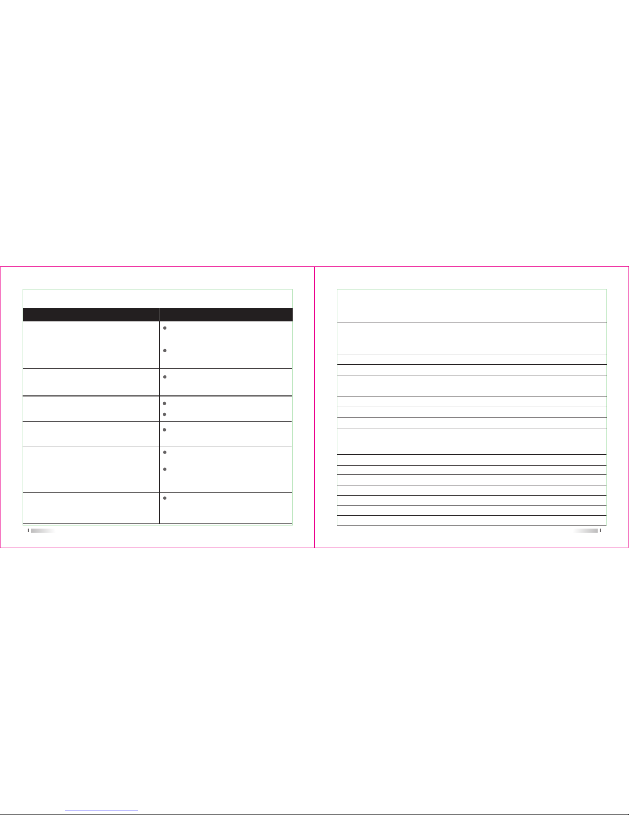
47
Problemlösung
Das Gerät startet nicht
Probleme Lösung
Die Batterie entlädt sich schnell
Ersetzen Sie sie durch eine geladene
Batterie oderladen Sie die Leere.
Die Batterie ist nicht korrekt eingesetzt.
Setzen Sie sie richtig ein.
Ersetzen Sie sie durch eine neue
Batterie.
Die Kommunikation mit der eigenen
Gruppe ist in schlechter Qualität.
Die Stimme einer anderen Gruppe kann
gehört werden.
Bestätigen Sie die QT / DQT gleich ist.
Sie sind zu weit voneinander entfernt.
Ändern Sie alle QT/DQT der Gruppe.
Bei der Übertragung empfängt der
Gesprächspartner das Signal nicht oder
die Signale in ein geringes Volumen
erhalten.
Wechseln Sie den Lautstärkeregler
auf höchstem Niveau.
Das Mikrofon kann beschädigt werden.
Schicken Sie es an den Händler vor
Ort zu überprüfen.
Lärm wird immer gehört.
Sie sind zu weit voneinander entfernt.
Schalten Sie das Radio in näheren
Bereich und versuchen Sie es erneut.
48
*2.5PPm
DC 7.2V (Rechargeable Li-ion battery)
128*2
High gain antenna
50Ω
Simplex or semi-duplex
3600mAh
Frequenzstabilität
Betriebsspannung
Kanal Nr.
Antenne
Antennen Impedanz
Betriebsmodus
Akku-Kapazität
Spezifikationen
Allgemeine
Frequenzbereich
Receiver
RF- Empfindlichkeit
Ausgangsleistung
Audioverzerrungen
Blocking
Intermediation
Selektivität
Unechte Ablehnung
-122dBm (12dB SINAD)
>0.5W
<10%
*85dB
*60dB *55dB
*65dB *60dB
*65dB
136-174MHz/220-260MHz
220-260MHz/400-520MHz
136-174MHz/400-520MHz
Page 57

49
Hinweis:
Technische Daten werden ohne vorherige Ankündigung geändert werden,wenn die
Technik gesteigert hat.Vielen Dank.
Sender
*10W *5W
16k*F3E / 11k*F3E
<5KHz / <2.5KHz
*-65dB / *-60dB
<7µW
6dB
*2.8A(10W) *1.8A(5W)
0.55KHz*0.15KHz 0.4KHz*0.1KHz
8-12mV
<5%
Ausgangsleistung
Modus der Modulation
Maximale Abweichung
Adjacent Ch. power
Störende Strahlung
Preemphasis-Merkmale
Strom
CTCSS/DCS Abweichung
Vermittlung-Empfindlichkeit
Vermittlung-Verzerrung
Page 58

Hinweis:
1. Diese Garantiekarte gilt nur
für das Produkt wie oben
aufgeführte Modell und
Seriennummer.
2. Die Garantiekarte ist ein
wichtiges Dokument für den
Verbraucher, Garantieservice
zu genießen..
3. Die Garantiekarte werden
vom Händler ausgefüllt und
ausgegeben,sonst ist es
ungültig
Geschlecht:Name des Käufers:
Adresse and PLZ:
Tel-Nr.:
Modell:
Serien-Nr.:
Kaufdatum:
Rechnung Nr..:
Händler:
Adresse and PLZ von der Händler:
Kontakt Tel:
Behandlung von Menschen:
Stempel:
Garantiekarte
Diese Garantiekarte werden vom Benutzer gehalten .Wenn Sie
es vergessen haben, gibt es keinen Nachschub.
Wartung-Datensatz
Carry-in datum
Abschluss
Datum
Defekt
Beschreibung
Wartung
Mitarbeiter Nr.
Wartung
Personal Nr..
Unterschrift
Vielen Dank für den Einkauf.Wir werden unser
Bestes versuchen, um einen guten Kundenservice
bereitzustellen.Wenn weiterhin Probleme
auftreten, kontaktieren Sie ihren Händler, den
Vertrieb oderdas Service-Center.Bitte
konzentrieren sich auf die folgenden
Informationen:
Das beschriebene Gerät trägt das Garantiezertifikat für ein
Jahr ab Kaufdatum zum Endkunden.Bitte bringen Sie die
Garantiekarte und Quittung an eine bestimmte autorisierte
Zweigniederlassung für iReparatur,wenn das Gerät Probleme
innerhalb die Gewaehrleistung hat. (Das Produkt ist für 12
Monate garantiert.Aber das Zubehör ist nur
für 6 Monate garantiert.)
Während Reparatur können die folgenden Situationen Gebühr
anfallen.:
(1) Sie können keine Garantiekarte vorzeigen.
(2) Bei Geräten,die von jemandem anderen, als qualifizierten
Servicemitarbeitern manipuliert wurden.
(3) Abnorme Schaden
(4) Schäden durch Missbrauch, Unfall, Wasser oder
Fahrlässigkeit.
(5)Schäden durch unsachgemäße Prüfung, Betrieb, Wartung,
Installation, Demontage oder Anpassung,
(6) Schäden durch nicht autorisierte Reparatur
(7)Schäden durch höhere Gewalte
Die Garantie ist nur gültig, wenn das Zertifikat
vollständig, richtig und klar leserlich ausgefüllt ist und die
Bezeichnung des Händlers und dessen Stempel eingetragen
sind. Es muss der Kaufnachweis angefügt sein.
 Loading...