

Page 1
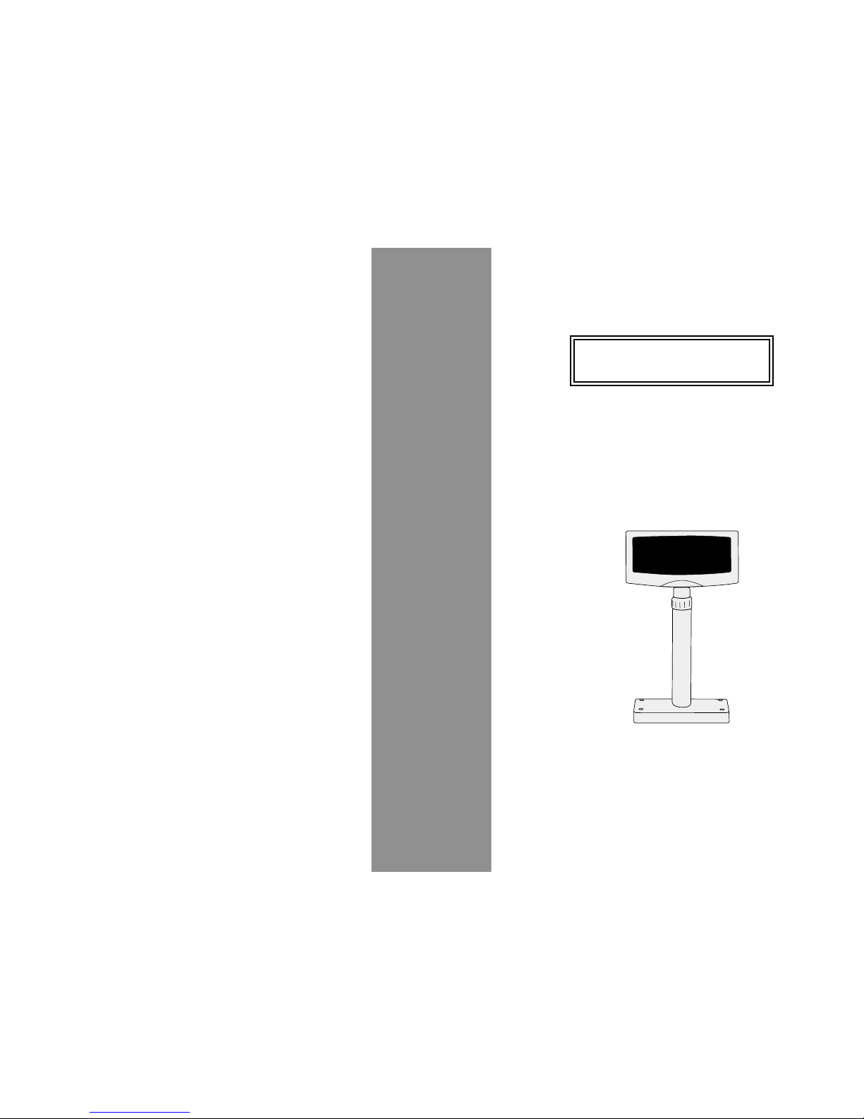
VFD-450/550 Series
VFD Customer Display
User's Manual
Page 2

-1-
Contents
1. Information
2. Installation
3. Interfaces
5. Specifications
2
3
4
.............................................................
A. Standard Package................................................ 2
B. Optional Accessories........................................... 2
...............................................................
.................................................................
............................................ 7
.......................................................... 14
................................................. 16
7 .............................. 22
........................... 25
Mode 0 VFD-450/550............................................. 25
Mode 1 EPSON Esc/POS........................................26
Mode 2 UTC Standard............................................ 27
Mode 3 UTC Enhanced.......................................... 28
Mode 4 AEDEX...................................................... 28
Mode 5 ICD 2002................................................... 29
Mode 6 CD 5220.................................................... 31
Mode 7 DSP-800.................................................... 33
Mode 8 ADM 787/788............................................ 34
4. Character Fonts Table
6. System Commands
. VFD Function Demo Software
Appendix: Select Command Modes
Page 3
VFD Customer Display
Model VFD Series
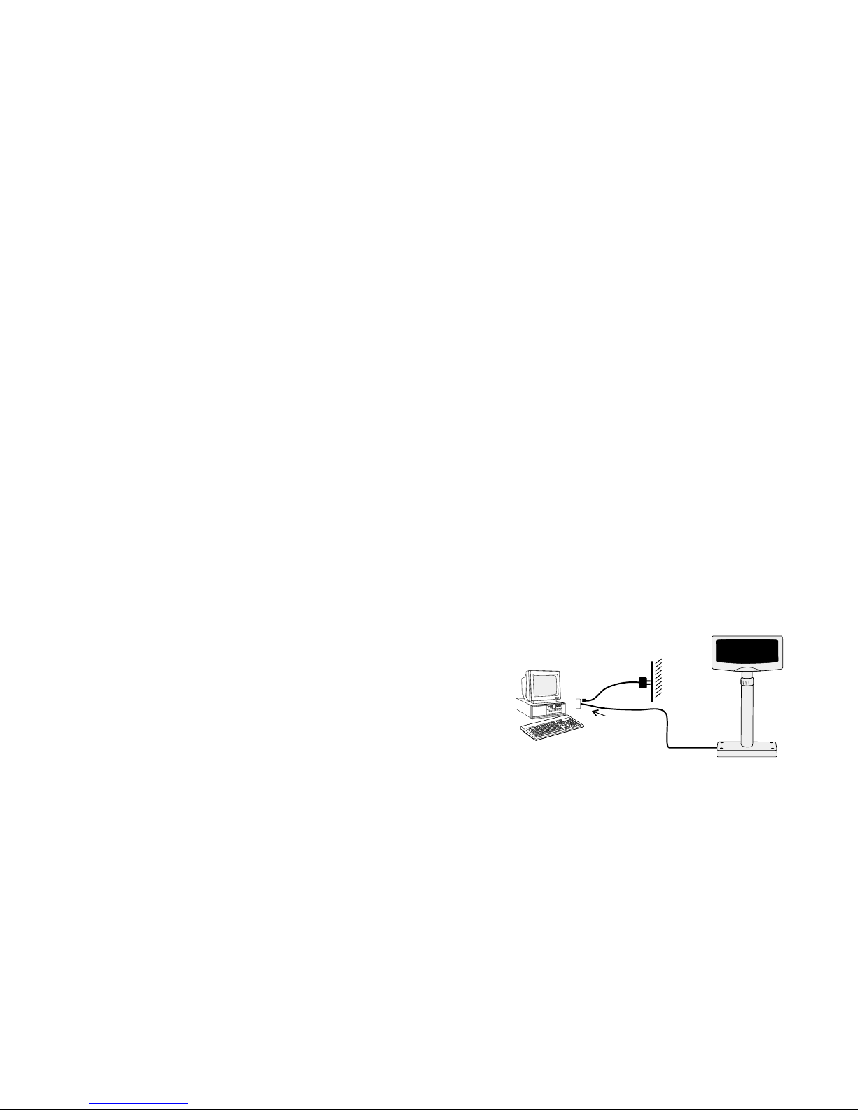
2. Installation (RS-232 Interface)
1.Information
A. Standard Package:
B. Optional Accessories:
1. Display Unit 1 PC
2. User's Manual 1 PC
3. Demo Software and Utility Diskette 2 PCS
4. Power Kit 1 PC
to retrieve power 12 VDC from switching power
supply inside computer
1. Switch-Mode Power Supply:
Input: 100V AC~240V AC, 50Hz~60Hz
Output: DC 9V, 1.33A
2. Y-connection cable: for printer pass-through connection
3. Option Pole/Base:
a. DSP-B01: Long pole with small round base
b. DSP-B02: Metal base (should be used with DSP-B01)
c. DSP-B03: Short pole with square base
d. DSP-B04: Side wall mounting brocket (used with
DSP-B01)
4. Option Double Sides Display:
a. VFD-488: Double sides VFD Display
b. VFD-455: Front VFD with Back LCD Display
Step 1: Turn the computer system power off.
Step 2: Connect the Display Cable to the RS-232 Port of
the computer.
Step 3: Connect the DC power source by the appropriate
DC power adapter.
Step 4: Turn on the computer and the power supply unit,
the display will be on and ready for receiving data.
-3--2-
To RS-232 port
AC power
Source
Extension
RS-232 Cable
Page 4
-4- -5-
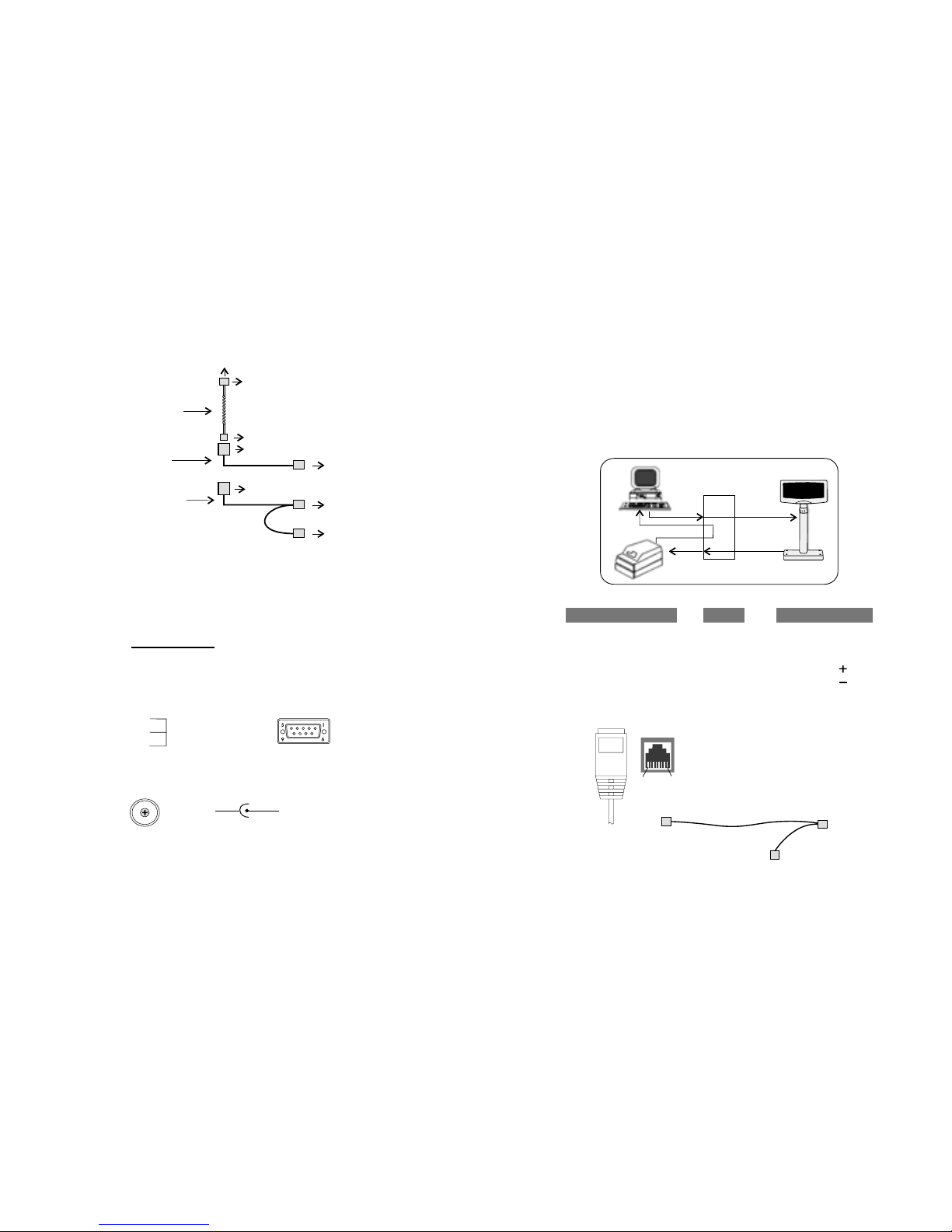
3. Pass-through Connection
All the data transmitted from the host will be processed,
and if it is for the printer, it will be transmitted to the printer.
Whether the data is for the display or the printer can be
switched using the peripheral device selection command.
To Display To Printer From Host
TXD 1-------------------------------------- 2
RXD 2-------------------------------------- 3
VCC 3--------------------------------------------------- (INNER)
GND 4-------------------5----------------- 5---------- (Outer)
FROM NEXT 5-------------------2
TO NEXT 6-------------------3
1+4+6 (SHORT)
7+8 (SHORT)
RJ45(8P8C) JACK DB9M DB9F+DC JACK
Transmit data from host
Interface conversion
Transmit data from printer
data for printer
18
To Display
RJ45 JACK
From Host
DB9F+DC
To Printer
DB9M
For pass-through connection, the RS-232 cable should
be replaced by the pass-through cable.
1. RS-232 Cable-end
2. DC Power Jack
3. Interfaces (Cable Connections)
DSUB-9F Connector
2
3
5
7
8
9
1
4
6
TX
RX
GND
CTS
RTS
VCC
Short Connection
GND 9~12VDC/1000~1500 mA
RS-232
Cable
Pass-Through
Cable
RJ-45 Female Connector
RJ-45 Male Connector
RJ-45 Female Connector
7 pin Male-Header
Connect to Display Panel Side
DB9M, to Printer
DB9F+DC Jack, to Host
Display
Main Cable
(Inside the Pole)
Connect to Host
DB9 Female with DC Jack
Page 5

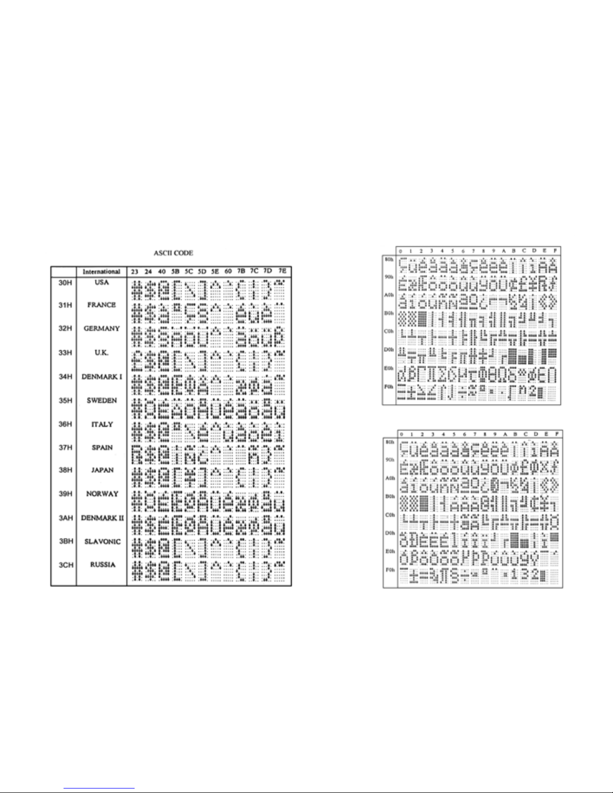
4. Character Fonts Table
-7-
-6-
4.1 Control code set
4. Interface of Display Panel Side
- Specifications
- Interface connector
Data transmission method : Asynchronous Serial.
Default protocol : 9600 bps, non-parity,
8 data bits, 1 stop bit.
(display panel side)
7 pin Male-Header
Pin assignments:
1
7
TXD
DSR
RXD
DTR
GND
GND
VCC
4.2 U.S.A. font set
Page 6
3DH: Standard Europe international font set
3EH: Multingual international font set
4.3 International character selection
-9-
-8-
Hex. Value
-8-
Page 7

41H: NORDIC internatinal font set
42H: RUSSIA font set
3FH: Portuguese international font set
40H: Canadian French international font set
-11-
-10-
Page 8

43H: SLAVONIC Font set
44H: Katakana font set
-13-
-12-
Page 9

-15--14-
5. Specifications:
D. Overall Dimensions:
E. Electricity
•
•
•
•
•
•
•
•
•
•
•
Dimension (panel) 110mm H x 220 mm L x 45 mm D
Dimension (support) Telescopic pole from 270
to 440 mm
Dimension (base) 12 mm Height with 80mm OD
Viewing angle Max. 45
Horizontal rotation Max. 360
Weight About 0.8 Kg
Power source DC +9V~12V (Optional +5V, +24V)
Power consumption 4.5 watts for single side display
8.0 watts for double sides display
Central control unit CPU 8031 BH
ROM 64K flash ROM
RAM 32K SRAM
Speed 29 MHz
Connector 8 pins phone jack, D-SUB 9,
or 25 pins connector
o
o
A. Tube Display:
B.Environment:
C. Driver Interface:
VFD Display
•
•
•
•
•
•
•
•
•
•
•
•
Customer display Vacuum Fluorescent Display
Display pattern 5 x 7 dot matrix
Brightness 700 cd/m
Character type 96 Alphanumeric & 13 Kinds
of international character set
and user definable character
set.
Character size 6.4mm (W) x 9.2mm(H)
Character number 20 x 2(40 characters) /
20 x 2x 2(80 characters)
Character font 5x7 dots matrix, comma,
decimal point
Driver interface RS-232
Driver command ESC commands
2
Operating temperature 0 C to +40 C
Storage temperature -10 C to +50 C
Relative humidity 0% to 90% RH
oo
oo
Page 10

-17-
-16-
6.2.2. Select international code table
6.2.3. Save the current view message
COMMAND: I
COMPUTER:EOT SOH 'I' 'CHAR' ETB
ASCII(04H)(01H)(49H)(30H~44H)(17H)
Byte 1 1 1 1 1
DISPLAY: ACK (or NACK if failed)
ASCII (06H) (15H)
Byte 1 1
Note : International Character Code
Please refer to 4.3 International Character Selection.
(Save Demo view data)
COMMAND: S
COMPUTER:EOT SOH 'S' 'Layer' ETB
ASCII(04H)(01H)(53H)(31H~33H)(17H)
Byte 1 1 1 1 1
DISPLAY: ACK (or NACK if failed)
ASCII (06H) (15H)
Byte 1 1
Note : 31H: Layer 1 / 32H: Layer 2 / 33H: Layer 3
6. System Commands
6.1. Command format
6.2. Commands list
EOT SOH COMMAND ETB
6.2.1. Set Baud Rate
COMMAND: B
COMPUTER:EOT SOH 'B' 'BAUD RATE' 'N' ETB
ASCII (04H) (01H)(42H) (31H~37H) (4EH)(17H)
Byte 1 1 1 1 1 1
DISPLAY: ACK (or NACK if failed)
ASCII (06H) (15H)
Byte 1 1
Note: Baud rates
31H : 9600
32H : 4800
33H : 2400
34H : 1200
35H : 600
36H : 300
37H :19200
End of Transmission Block
(17 Hex)
See Command list
Start of Heading
(01 Hex)
(04 Hex)
30H :
31H :
32H :
33H :
34H :
35H :
36H :
37H :
38H :
39H :
3AH :
U. S. A.
France
Germany
U. K.
Denmark I
Sweden
Italian
Spain
Japan
Norway
Denmark II
3BH :
3CH :
3DH :
3EH :
3FH :
40H :
41H :
42H :
43H :
44H :
Slavonic
Russia
Standard Europe International font set
Multingual International font set
Portuguese International font set
Canadian French International font set
Nordic International font set
Russia font set
Slavonic font set
Katakana font set
Page 11

-19--18-
6.2.4. Set cursor position
6.2.5. Clear display range
6.2.6. Display the saved DEMO message
COMMAND: P
COMPUTER: EOT SOH 'P' 'Position' ETB
ASCII (04H) (01H) (50H) (31H~58H) (17H)
Byte 1 1 1 1 1
DISPLAY: ACK (or NACK if failed)
ASCII (06H) (15H)
Byte 1 1
COMMAND: C
COMPUTER: EOT SOH 'C' 'START' 'END' ETB
ASCII (04H)(01H)(43H)(31H~58H)(31H~58H)(17H)
Byte 1 1 1 1 1 1
DISPLAY: ACK (or NACK if failed)
ASCII (06H) (15H)
Byte 1 1
Note:Some part of the current view messages can be cleared by
this COMMAND. It can start clearing between position 1
and position 40.
COMMAND: D
COMPUTER: EOT SOH 'D' 'Layer' 'Mode' ETB
ASCII (04H)(01H)(44H)(31H~37H)(31H~33H)(17H)
Byte 1 1 1 1 1 1
DISPLAY: ACK (or NACK if failed)
ASCII (06H) (15H)
Byte 1 1
Note: The cursor can be set to the position from 1 to 40
Position 1 means the upper left corner position.
Position 20 means the upper right corner position.
Position 21 means the lower left corner position.
Position 40 means the lower right corner position.
Note:
1) There are three layers of saved view messages as described
on COMMAND "S"
2) There are two modes of display:
Mode 1 is running the saved messages from right to left,
which is a horizontal scroll mode.
Mode 2 is running the saved messages from the lower line to
the upper line, which is a vertical scroll mode.
3) For display layers:
select 31H means display the message saved on layer 1.
select 32H means display the message saved on layer 2.
select 33H means display the message saved on layer 1+
layer 2.
select 34H means display the message saved on layer 3.
select 35H means display the two messages saved on layer 1
+ layer 3.
select 36H means display the two messages saved on layer 2
+ layer 3.
select 37H means display all the messages saved on layer 1
+ layer 2 + layer 3.
4) For display modes,
select 31H means display the message with Mode 1.
select 32H means display the message with Mode 2.
select 33H means display the message with Mode 1+Mode 2.
For this Demo display function, you must have saved the
message by COMMAND "S" previously, For example, select
37H for displaying layers and select 33H for displaying
modes, DSP would display all the three messages saved on
layer 1+ layer 2 + layer 3 with both Mode 1 + Mode 2
displaying modes.
5) Any new message from the computer would stop this Demo
display function and DSP would display that new message
from the computer.
Page 12

6.2.7. Select the Command Mode
6.2.8. Set all default
6.2.9. Select the drive ON/OFF setting
COMMAND: M
COMPUTER: EOT SOH 'M' 'Mode' ETB
ASCII (04H) (01H) (4DH)(30H~38H) (17H)
Byte 1 1 1 1 1
DISPLAY: ACK (or NACK if failed)
ASCII (06H) (15H)
Byte 1 1
COMMAND: X
COMPUTER: EOT SOH 'X' ETB
ASCII (04H) (01H) (58H) (17H)
Byte 1 1 1 1
COMPUTER: ESC 'G'
ASCII (1BH) (47H)
Byte 1 1
Note:
(This command feature is for Y cable printer passthrough connection only.)
PRINTER ON COMMAND:
PRINTER OFF COMMAND:
COMPUTER: ESC 'S'
ASCII (1BH) (53H)
Byte 1 1
Note: The driver feature mode selections are as
following:
a. PRINTER ON COMMAND (Format as above)
features PRINTER ON and DISPLAY OFF
b. PRINTER OFF COMMAND (Format as above)
features PRINTER OFF and DISPLAY ON
Each ASCII character is transmitted with
1 start bit
8 data bits
1stopbit
No parity
Note: You may generate your own application software to
run the display according to the standard RS-232C
communication protocols and the SOFTWARE
CONTROL information listed on this chapter.
6.3. Transmission method
-21--20-
30H : VFD-450/550
31H : EPSON ESC/POS
32H : UTC/S
33H : UTC/E
34H : AEDEX
35H : ICD 2002
36H : CD 5220
37H : DSP-800
38H : ADM 787/788
Command Modes Selection
Page 13

-22-
5. Then, follow this menu to run the demo software.
a. Click "Set COM Port and Baud Rate", to set
RS-232 communication of the computer. Select
COM port, baud rate must also be set as the
same as the baud rate shown on the lower line
of the display, such as "9600 N 8 1" means
baud rate 9600, no parity, 8 data bits, and 1
stop bit.
b. Click "International Character Set" to select
International character Code Set.
c. Click "Command Type Select" to select the
command type that you want the display to run.
d. Click "Clear Range" to select the start and end
position that you want to clear.
e. Click "Set Cursor Position" to move the cursor
position.
f. Click "Save Current View Message" to save the
current view message into the memory of
Display.
g. Click "Display Demo Message" to display the
previously saved message.
h. Click "Set All Default" to default the Display
as it just come from manufacturer.
7. VFD Function Demo Software
(Windows Version)
Note: For the first installation, you had better connect
the Display with the COM1 port of the computer
due to the initial value COM1 for Display
1. Find the enclosed two diskettes.
2. Make sure the installation of Display is completed.
3. Enter the Windows system to start your computer.
4. Copy the software of bundled diskettes from Drive
A: into sub-directory VFD of Hard Drive C: in
your computer under Windows system, then
execute setup.exe and install the VFD Function
Utility. After successfully installing, you can find
VFD file in Program Files, click the VFD file, you
will see the following screen:
7.1. How to run the demo software
-23-
Page 14

-24-
7.2. After the handshaking between the Display
and computer is completed, the Display
would display any message character from
the computer. Any new message from the
computer would cover the old message on
the display. You may enter any message to
display.
Note: First of all, instal the Display to the
COM1 of your computer to run this
demo software. The Default value of
Display communication parameters are:
COM port : COM1
Baud rate = 9600
Parity = None
Databits =8
Stop bit = 1
-25-
Appendix:
SELECT COMMAND MODES
Refer to Chapter 7 VFD Function Demo Software, you
can select various command modes which are compatible
to most popular displays, then the user can easily replace
the used display and no need to modify the application
software.
Mode 0 : VFD-450/550 (Default setting)
Mode 1 : EPSON Esc/POS
Mode 2 : UTC Standard
Mode 3 : UTC Enhanced
Mode 4 : AEDEX
Mode 5 : ICD 2002
Mode 6 : CD 5220
Mode 7 : DSP-800
Mode 8 : ADM 787/788
Mode 0: VFD-450/550 mode commands list
Refer to page 16
Command Hexadecimal Function
Codes
B 42H Set baud rate and parity
I 49H Select international character set
S 53H Save the current view message
P 50H Set cursor position
C 43H Clear display message
D 44H Display the saved DEMO message
ESC G IBH 47H Printer ON command
ESC S IBH 53H Printer OFF command
M 4DH Select command mode
X 58H Set all default
Page 15

Mode 1: EPSON Esc/POS mode commands list
Command Code description Function description
(hex)
HT 09 move cursor right
BS 08 move cursor left
US LF 1F 0A move cursor up
LF 0A move cursor down
US CR 1F 0D move cursor to right-most position
CR 0D move cursor to left-most position
HOM 0B move cursor to home position
US B 1F 42 move cursor to bottom position
US $ x y 1F 24 x y move cursor to specified position
X=1-20 y=01,02
CLR 0C clear display screen
CAN 18 clear cursor line
US E n 1F 45 n n=00-ff blink display screen
ESC @ 1B 40 initialize display
ESC R n 1B 52 n n=30~44 select international character set
US MD1 1F 01 specify overwrite mode
US MD2 1F 02 specify vertical scroll mode
US MD3 1F 03 specify horizontal scroll mode
ESCWnsx11B57nsx1y1x2y2 specify/cancel the window range
y1 x2 y2 n=1,2,3,4 1<=x1<=x2<=20
s=0, 1 1<=y1<=y2<=2
ESC = n 1B 3D n select peripheral device
n=31H, enable printer, n=32H (default)
disable display
n=32H, enable printer,
disable printer
n=33H, enable printer,
enable printer
n=34H, message for only for double sides display
customer side
n=35H, message for
operator side
Command Code description Function description
Command Code description Function description
(hex)
US: 1F 3A set starting/ending position of
macro definition
US ^ n m 1F 5E n m execute and quit macro
00<=(n,m)<=ff
US @ 1F 40 execute self-test
US T h m 1F 54 h m display time
0<=h<=17,
0<=m<=3b
US U 1F 55 display time continuously
US.n 1F 2E n n= a displayable character code
Display the code with a dot
US,n 1F 2C n n= a displayable character code
Display the code with a comma
US;n 1F 3B n n= a displayable character code
Display the code with a semicolon
US#nm 1F 23 n m Turn the anuciator ( ) ON/OFF
n=0ro1
0 <=m<=20
(hex)
BS 08 back space
HT 09 horizontal tab
LF 0A line feed
CR 0D carriage return
DLE 0F display position
DC1 11 over write display mode
DC2 12 vertical scroll mode
DC3 13 cursor on
DC4 14 cursor off
ESC d 1B 64 change to UTC enhanced mode
US 1F clear display
Mode 2 : UTC standard mode commands list
-26- -27-
Page 16

-28- -29-
Mode 3 : UTC enhanced mode commands list
Command Code description Function description
(hex)
ESC u ACR 1B 75 41 [ data x 20] 0D upper line display
ESC u BCR 1B 75 42 [ data x 20] 0D bottom line display
ESC u DCR 1B 75 44 [ data x 20] 0D upper line message scroll
continuously
ESC u ECR 1B 75 45 hh ':' mm 0D display time
h,m='0'-'9'
ESC u FCR 1B 75 46 [ data x 20] 0D upper line message scroll
once pass
ESC u HCR 1B 75 48 n m 0D change attention code
20h<=n,m
ESC u ICR 1B 75 49 [ data x 40] 0D two line display
ESC RS CR 1B 0F 0D change to UTC standard
mode
Mode 4 : AEDEX mode commands list
Command Code description Function description
(hex)
! # 1CR 21 23 31 [ data x 20] 0D upper line display
! # 2CR 21 23 32 [ data x 20] 0D bottom line display
! # 4CR 21 23 34 [ data x 20] 0D upper line message scroll
continuously
! # 5CR 21 23 35 hh ':' mm 0D display time
h,m='0'-'9'
! # 6CR 21 23 36 [ data x 20] 0D upper line message scroll
once pass
! # 8CR 21 23 38 n m 0D change attention code
20h<=n,m
! # 9CR 21 23 39 [ data x 40] 0D two line display
! # ACR 21 23 41 [ data x 20] 0D upper line scroll message
! # BCR 21 23 42 [ data x 20] 0D bottom line display message
Mode 5 : ICD 2002 mode commands list
Command Code Function description
description
(hex)
HT 09 move cursor right
(only valid in overwrite mode)
BS 08 move cursor left
(only valid in overwrite mode)
CR 0D move cursor to left-most position
(only valid in overwrite mode)
ESC @ 1B 40 initialize customer display to initial
state, clears display buffer, set display
mode to shift and sets current display
row to upper row
ESC U 1B 55 select upper row as current row
(initial default)
ESC D 1B 44 select lower row as current row
ESC A z 1B 41 z sets customer display disable or
enable
z 'D'=disable,
'E'=enable
ESC C r c 1B 43 r c move cursor to specified position
(only valid in overwrite mode)
-r Row
( 'U'=upper,'D'=lower)
-c Column number
(range from 1~20)
ESC E r z 1B 45 r z set special effect or display mode of
specified row
Page 17

-30-
-31-
Command Code Function description
description
(REMARK)*
(hex)
ESC R n 1B 52 n set international font sets
n=30~44 -n international fonts code
ESC = n 1B 3D n select peripheral
n=31~33 -n 31=printer only,
32=customer display only,
33=both peripheral
n=34H only for double sides display
n=35H n 34=message for customer side
35=message for operator side
Using command "ESC E r z", the value of
parameter:
r 58 = all rows
55 = upper row
44 = lower row
z special function, the value is one of
30 = shift mode(default display mode)
31 = rotation mode
32 = blink mode
33= clear this row and switch to shift mode
34= overwrite mode
35= vertical mode
Mode 6: CD 5220 standard mode commands list
Command Code description Function description
(hex)
ESC DC1 1B 11 overwrite mode
ESC DC2 1B 12 vertical scroll mode
ESC DC3 1B 13 horizontal scroll mode
ESC Q A.....CR 1B 51 41 [n]x20 0D set the string display mode,
write string to upper line
ESC Q B.....CR 1B 51 42 [n]x20 0D set the string display mode,
write string to lower line
ESC Q D.....CR 1B 51 44 [n]x20 0D upper line message scroll
continuously
ESC [ D 1B 5B 44 move cursor left
BS 08 move cursor left
ESC [ C 1B 5B 43 move cursor right
HT 09 move cursor right
ESC [ A 1B 5B 41 move cursor up
ESC [ B 1B 5B 42 move cursor down
LF 0A move cursor down
ESD [ H 1B 5B 48 move cursor to home position
HOM 0B move cursor to home position
ESC [ L 1B 5B 4C move cursor to left-most
position
CR 0D move cursor to left-most
position
ESC [ R 1B 5B 52 move cursor to right-most
position
ESC [ K 1B 5B 4B move cursor to bottom
position
ESC 1 x y 1B 6C x y move cursor to specified
1<=x<=20, y=1,2 position
Page 18

-32- -33-
Command Code description Function description
(hex)
ESC @ 1B 40 initialize display
ESC W s x1 x2 y 1B 57 1 x1 x2 y set or cancel the
1<=x1<=x2<=20 window range at horizontal
y=1,2 scroll mode
CLR 0C clear display screen, and
clear string mode
CAN 18 clear cursor line, and clear
string mode
ESC _ n 1B 5F n n=0,1 set cursor ON/OFF
ESC f n 1B 66 n n=30~44 select international fonts set
ESC = n 1B 3D n select peripheral device,
n=31,32,33 Display or Printer
n=31 select printer ON,
display off
n=32 select display ON,
display off
n=33 select both
Mode 7: DSP-800 mode commands list
Command Code Function description
description
(hex)
EOT SOH I n ETB 04 01 49 n 17 select international fonts
set.
EOT SOH P n ETB 04 01 50 n 17 move cursor to specified
n=31H-58H position
EOT SOH C n m ETB 04 01 43 n m 17 clear display range from
position to position and
move cursor to position.
EOT SOH S n ETB 04 01 53 n 17 save the current displaying
n=31H-35H data to n layer for demo
display
EOT SOH D n m ETB 04 01 44 n m 17 display the saved data
n=31H-4FH
m=31H-33H
ESC G IBH 47H Printer ON
ESC S IBH 53H Printer OFF
Select the driver ON/OFF
EOT SOH T ETB 04 01 54 17 transmit the current
view message to computer
EOT SOH B n N ETB 04 01 42 n 4E 17 set baud rate
n=31H: 9600
n=32H: 4800
n=33H: 2400
n=34H: 1200
n=35H: 600
n=36H: 300
n
m
n
31H<=n<=m<=58H
30H : U. S. A.
31H : France
32H : Germany
33H : U. K.
34H : Denmark I
35H : Sweden
36H : Italian
37H : Spain
38H : Japan
39H : Norway
3AH : Denmark II
3BH : Slavonic
3CH : Russia
3DH : Standard Europe International font set
3EH : Multingual International font set
3FH : Portuguese International font set
40H : Canadian French International font set
41H : Nordic International font set
42H : Russia font set
43H : Slavonic font set
44H : Katakana font set
Page 19

Mode 8: ADM 787/788 commands list
Command Code description Function description
(hex)
CLR 0C clear display
CR 0D carriage return
SLE1 0E clear upper line and move
cursor to upper left-end
position
SLE2 0F clear bottom line and move
cursor to bottom left-end
position
DC0 10 n set period to upper line, last
n position 31h n 37h
DC1 11 n set line blinking, upper line
n ='1', bottom line n='2'
DC2 12 n clear line blinking, upper line
n ='1', bottom line n='2'
SF1 1E clear field 1 and move cursor
to field 1, first position
SF2 1E clear field 2 and move cursor
to field 2, first position
<<
-34-
 Loading...