

Page 1
TP-7715
Fanless True-Flat Touch Screen POS System
Service Manual
Page 2

Copyright © 2019 Fametech Inc. All Rights Reserved.
All other brands, product names, company names, trade names, trademarks and service marks used
herein are the property of their respective owners.
2
Contents
Before Using the Product 4
Revision History 4
Read This First 5
Safety Information 5
Information on Copyrights 7
System Disassembly 11
Before You Start 11
Remove all the Peripherals (MSR, i-Button Module, or Customer Display)
from the POS Unit 12
Disconnect the Devices from the I/O Ports 13
Remove the 1st HDD/SSD Drive from the POS Unit (Quick Detach) 14
Detach the Panel Unit from the Base Unit 16
Remove the Power Adapter from the Base Unit 17
Disassemble the POS Unit (with Motherboard Set) 18
1. Remove the Back Cover of the POS Unit 18
2. Remove the RAM Module 20
3. Remove the CPU 21
4. Disconnect the HDD/SSD Drive Bracket and Cable from the Modular Motherboard 22
5. Disconnect the Wi-Fi Module 24
6. Disconnect the Dual USB Cable 25
7. Disconnect the LPT Cable 26
8. Disconnect all the Cables from the Motherboard 27
9. Remove the Touch Controller Board and Cable 28
10. Remove the Motherboard 32
11. Disconnect the Backlight and LVDS Cable 33
12. Remove the Speaker 34
13. Remove the LED Cable and the Power Switch 34
14. Remove the Metal Bracket of Bottom I/O Port 35
15. Remove the LCD Bracket 36
Page 3

Copyright © 2019 Fametech Inc. All Rights Reserved.
All other brands, product names, company names, trade names, trademarks and service marks used
herein are the property of their respective owners.
3
Remove the 2nd HDD/SSD Drive 38
1. Remove the 2nd HDD/SSD Drive from the Base (Quick Detach) 38
2. Remove the SATA Extended Cable of the 2nd HDD/SSD 39
Application Programs 43
BIOS Setting and CMOS Clear 43
Touch Utility Setting 46
Specifications 52
Motherboard Layout 52
Exploded View 53
Parts Description 54
Page 4
Copyright © 2019 Fametech Inc. All Rights Reserved.
All other brands, product names, company names, trade names, trademarks and service marks used
herein are the property of their respective owners.
4
Date
Version
Update Summary
Remark
Approved By
2019/9/6
V1.0
Initial Release
Joyce Huang
Robert Kuo
2019/9/10
V1.1
Modify Information
Joyce Huang
Robert Kuo
Before Using the Product
Revision History
Page 5

Copyright © 2019 Fametech Inc. All Rights Reserved.
All other brands, product names, company names, trade names, trademarks and service marks used
herein are the property of their respective owners.
5
Read This First
Before using your system, please read this manual carefully, and keep it on hand for future
reference.
• The contents of this manual may be changed without notice.
• Depend on the system model and type, some parts of this manual may differ from the
actual product.
• The basic drivers and utilities that come with your system are subject to change.
• TYSSO assumes no responsibility for damages resulting from a use of the product that is
not approved by TYSSO, or failure to follow the precautions and instructions provided in
this Service Manual.
• As some of the storage space is used for the system OS and built-in software, the actual
capacity available is less than the storage capacity listed in the product specifications. In
addition, the amount of available space may vary after you perform system OS and
software updates.
Safety Information
Please observe the following safety instructions to protect your computer from damage and
ensure your personal safety.
• Do not install the system in a location that is wet, damp, or near water. This may cause a
fire or an electrical shock.
• Only use the system in the specified power environment. The system may not work, and
may even cause a fire, if it is used with a different power source or equipment, or in a
country that has different power specifications.
• Make sure the plug is not bent or crushed by a heavy object. A damaged plug can cause a
fire or an electrical shock.
Page 6

Copyright © 2019 Fametech Inc. All Rights Reserved.
All other brands, product names, company names, trade names, trademarks and service marks used
herein are the property of their respective owners.
6
• Do not modify or extend the power cable. Cable damage may cause an electrical shock
or fire.
• Do not use a damaged power cord or plug, or a loose outlet. These may cause a fire,
short circuit, or electrical shock.
• Do not install the system in a location where it is likely to overheat or where it will be
exposed to direct sunlight. Ensure the system is kept a safe distance away from any
heating device. Installation in such locations could cause damage to the cabinet and the
electronic components.
• Do not drop or apply any strong shock to the system. This may cause damage to the
system.
• Do not use a sharp-pointed object on the display or apply excessive pressure to the
display. This may cause damage to the touch LCD display.
• Do not block or cover slots or openings in the system cabinet. These have been provided
for ventilation, to prevent the system from overheating.
• Do not use this system on a bed, sofa, rug or other similar surface.
• Never insert any object into the system through the cabinet openings, as they may touch
dangerous voltage points or short out parts, which could result in a fire or electrical
shock.
• Never spill liquid of any kind on the product.
• Unplug the system from the electrical power outlet before cleaning. Clean the system,
using a damp or dry cloth. Do not use abrasives, kerosene, benzene, thinner,
hydrochloric acid, or hot water, and do not use a tough sponge or a brush, as these may
cause discoloration or deterioration of the cabinet.
• Use only a 3-wire grounding type plug to avoid electric shock and damages due to short
circuits.
Page 7

Copyright © 2019 Fametech Inc. All Rights Reserved.
All other brands, product names, company names, trade names, trademarks and service marks used
herein are the property of their respective owners.
7
• If you have to use an extension cord, make sure that the total amperage rating of all
equipment plugged into it does not exceed the amperage rating of the extension cord and
only use a 3-wire grounding extension cord with a 3-prong grounding plug and outlet.
Information on Copyrights
Copyright
This publication, including all photographs, illustrations and software, is protected under
international copyright laws, with all rights reserved. Neither this manual, nor any of the
material contained herein, may be reproduced without written consent of the author.
Disclaimer
The information in this document is subject to change without notice. The manufacturer
makes no representations or warranties with respect to the contents hereof and specifically
disclaims any implied warranties of merchantability or fitness for any particular purpose. The
manufacturer reserves the right to revise this publication and to make changes from time to
time in the content hereof without obligation of the manufacturer to notify any person of such
revision or changes.
Trademark Recognition
All product names used in this manual are the properties of their respective owners and are
acknowledged.
About This Manual
The service manual provides service information for the TP-7715. This manual is designed to
help train service personnel to locate and fix failing parts on the machine.
Page 8

Copyright © 2019 Fametech Inc. All Rights Reserved.
All other brands, product names, company names, trade names, trademarks and service marks used
herein are the property of their respective owners.
8
This manual consists of the following sections:
Before Using the Product
System Disassembly
Application Programs
Specifications
FCC Statement
This device has been tested and found to comply with the limits for a Class A digital device,
pursuant to part 15 of the FCC Rules, these limits are designed to provide reasonable
protection against harmful interference when the device is operated in a commercial
environment. This device generates, uses and can radiate frequency energy and, if not
installed and used in accordance with this manual, may cause harmful interference to radio
communications. Operation of this device in a residential area is likely to cause harmful
interference in which case the user will be required to correct the interference at his/her own
expense.
FCC Warning
Changes or modifications not expressly approved by the party responsible for compliance
could void the user’s authority to operate the device.
Best Management Practice for Perchlorate Materials in California States
This device includes perchlorate in the lithium battery.
Perchlorate material-special handling may apply when handling this device.
Page 9

Copyright © 2019 Fametech Inc. All Rights Reserved.
All other brands, product names, company names, trade names, trademarks and service marks used
herein are the property of their respective owners.
9
Vermont Mercury Management Rules
LCD display lamps contain mercury. Dispose of them properly.
CE Mark
The above equipment was tested for compliance with the requirements set forth in the
EUROPEAN COUNCIL Directive 2014/30/EU and the technical standards mentioned above.
The results of testing in this report apply only to the product/system, which was tested. Other
similar equipment will not necessarily produce the same results due to production tolerance.
LVD
The equipment above has been tested in our facility and found compliance with the
requirement limits of applicable standards, in accordance with the DIRECTIVE 2014/35/EU*.
The test record, data evaluation and Equipment Under Test (EUT) configurations represented
herein are true accurate under the standards herein specified.
Legislation and WEEE Symbol
2012/19/EC Waste Electrical and Electronic Equipment Directive on the treatment, collection,
recycling and disposal of electric and electronic devices and their components.
The crossed-out wheeled bin symbol on the device means that it should not be disposed of
with other waste at the end of its working life. Instead, the device should be delivered to a
waste collection center for activation of the treatment, collection, recycling and disposal
procedure.
Page 10

Copyright © 2019 Fametech Inc. All Rights Reserved.
All other brands, product names, company names, trade names, trademarks and service marks used
herein are the property of their respective owners.
10
To prevent possible harm to the environment or human health from uncontrolled waste
disposal, please separate this device from other types of waste and recycle it responsibly to
promote the sustainable reuse of material resources.
Business users should contact their supplier and check the terms and conditions of the
purchase contract regarding its disposal.
It should not be mixed with other commercial waste for disposal.
Page 11

Copyright © 2019 Fametech Inc. All Rights Reserved.
All other brands, product names, company names, trade names, trademarks and service marks used
herein are the property of their respective owners.
11
System Disassembly
Before You Start
To prevent injuries to the LCD Panel:
• Carefully place the TP-7715on a flat, clean and stable surface.
(For example: a stable long table)
• Prepare additional cushioned material
(For example: a soft, clean blanket).
• Terminate the application running in the TP-7715, and shut down the operation system.
• Turn-off the power of TP-7715 and optional peripherals
(For example: thermal receipt printer, secondary LCD display)
• Disconnect all the devices or cables connected to the TP-7715.
• Disconnect and remove the Power Adaptor from the TP-7715.
• Unplug the power cables from the electrical outlet.
Note:
• There are no serviceable parts or components in the TP-7715 or peripherals.
DO NOT modify any parts of TP-7715 or use non-qualified parts or peripherals.
• Store the disconnected parts, cables, devices and screws in a secure location for further
use.
• For maintenance or replacement, please consult the technical personnel and contact the
local representative for purchasing the new peripherals and parts.
Page 12
Copyright © 2019 Fametech Inc. All Rights Reserved.
All other brands, product names, company names, trade names, trademarks and service marks used
herein are the property of their respective owners.
12
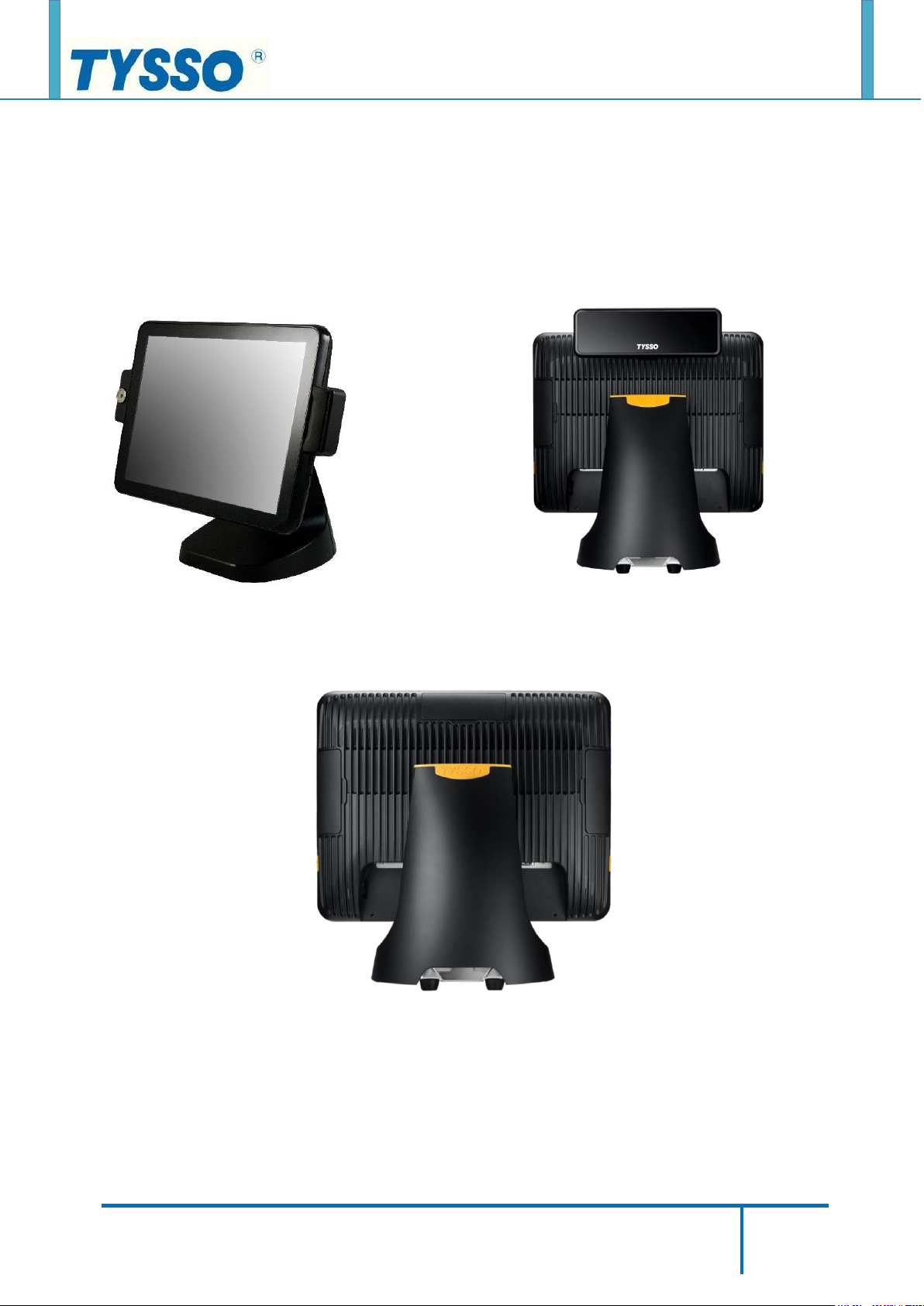
Remove all the Peripherals (MSR, i-Button Module, or Customer Display)
from the POS Unit
Please refer to the User Manual for the instructions of installation and disconnection
procedures.
POS Unit with MSR and i-Button POS Unit with Customer Display (VFD)
POS Unit without Optional Peripherals
Note:
Always store the detached MSR Module (or i-Button) and screws in a secure location for
further use.
Page 13
Copyright © 2019 Fametech Inc. All Rights Reserved.
All other brands, product names, company names, trade names, trademarks and service marks used
herein are the property of their respective owners.
13
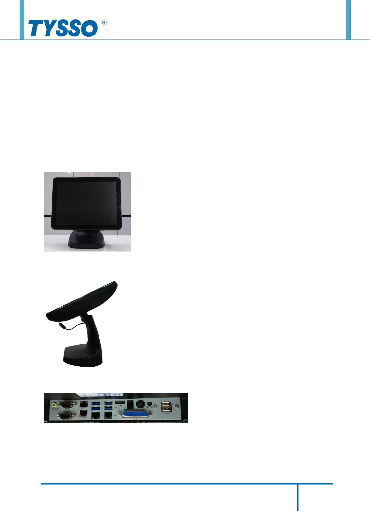
Disconnect the Devices from the I/O Ports
There are some of the optional peripherals or devices installed on the POS system.
Please detach the peripherals/devices and store them in a secure location.
Note:
Please turn off the whole POS system and devices before unplugging the cables from I/O
ports.
①. Place the POS terminal onto a stable and flat location.
②. Lift up the whole POS unit and examine the Bottom I/O ports of POS unit.
③. Disconnect all of the connected cables on the Bottom I/O Ports.
Note:
Always store the disconnected cables/devices in a secure location for further use.
Page 14
Copyright © 2019 Fametech Inc. All Rights Reserved.
All other brands, product names, company names, trade names, trademarks and service marks used
herein are the property of their respective owners.
14
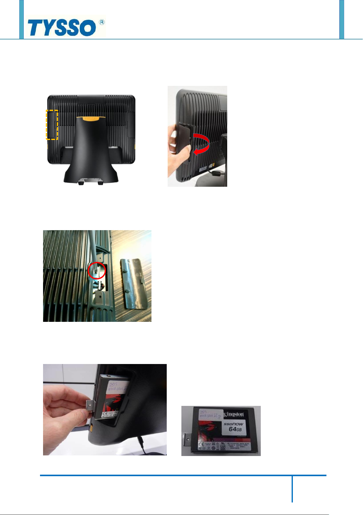
Remove the 1st HDD/SSD Drive from the POS Unit (Quick Detach)
①. Remove the Protective Cover (orange mark).
②. Loosen the securing screw of the HDD Drive Slot.
③. Pull out the HDD/SSD Drive Module.
Page 15
Copyright © 2019 Fametech Inc. All Rights Reserved.
All other brands, product names, company names, trade names, trademarks and service marks used
herein are the property of their respective owners.
15
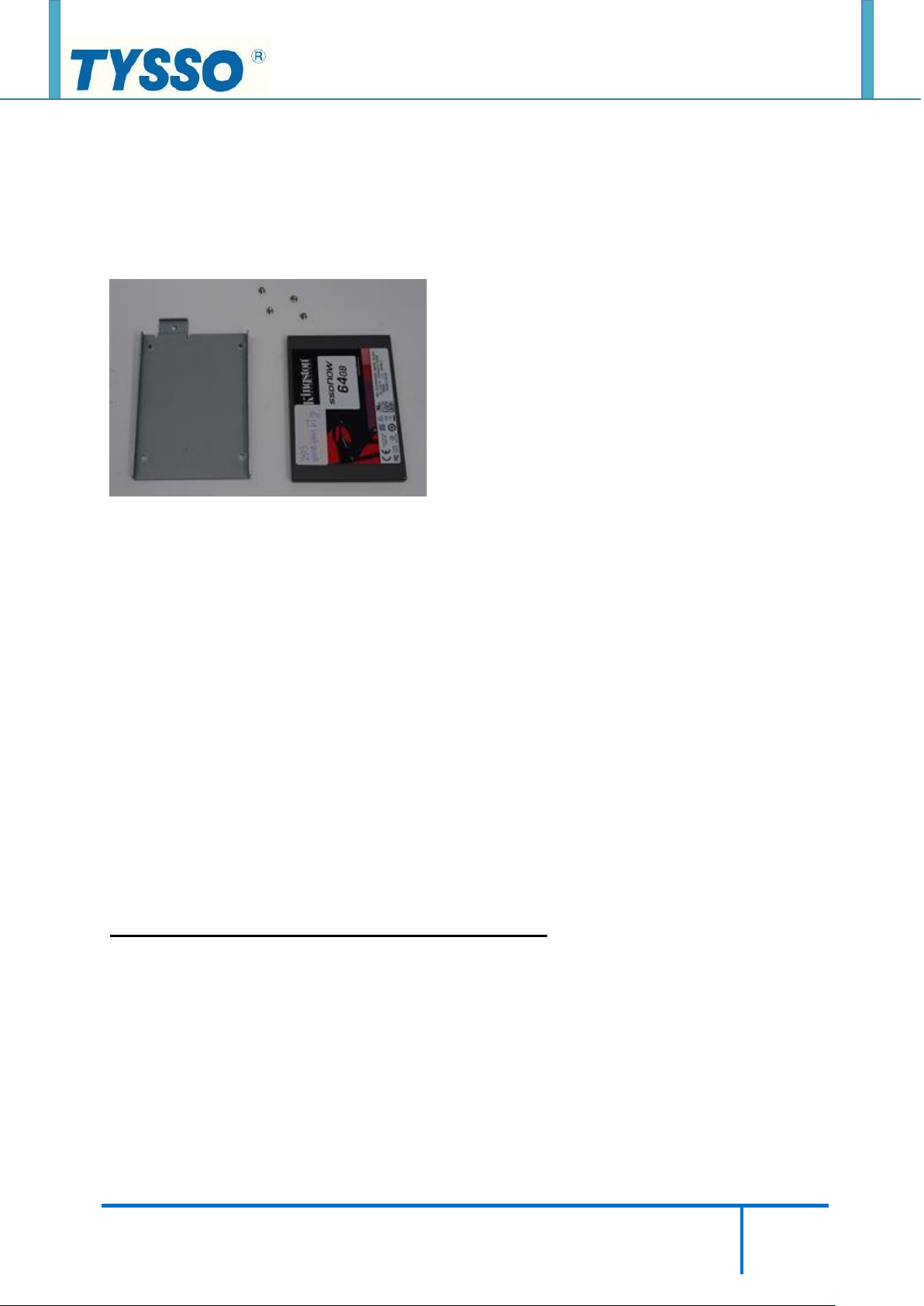
TIP: Replace the HDD/SSD Drive
To replace the HDD/SDD Drive:
1. Remove the securing screws of HDD/SSD Module.
2. Replace a new HDD or SSD drive and re-install to the HDD Bracket.
When Disassembling:
Please disassemble the HDD/SSD drive and HDD Bracket correctly.
Incorrect installation of HDD module may cause the system not functioning.
When Re-installing the HDD/SSD Module:
Beware the Direction of HDD/SSD module when re-install it back to the POS Unit.
Make sure the securing screw hole is matches to the HDD Drive Slot of POS Unit
DO NOT install the module in Wrong direction.
To re-install the HDD/SSD module back to the POS Unit,
DO NOT Push or pull the HDD/SSD module with force or it may damage the module and
POS Unit.
Page 16
Copyright © 2019 Fametech Inc. All Rights Reserved.
All other brands, product names, company names, trade names, trademarks and service marks used
herein are the property of their respective owners.
16
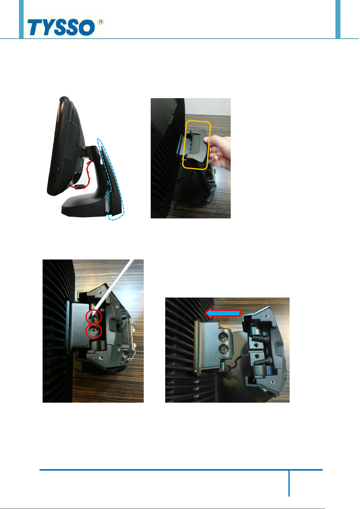
Detach the Panel Unit from the Base Unit
①. Remove the power cord (red dotted line), rear cover (blue dotted line), and top cover
(orange mark) of the base unit.
②. Loosen two hex socket head cap screws and detach the panel unit from the stand.
Page 17
Copyright © 2019 Fametech Inc. All Rights Reserved.
All other brands, product names, company names, trade names, trademarks and service marks used
herein are the property of their respective owners.
17
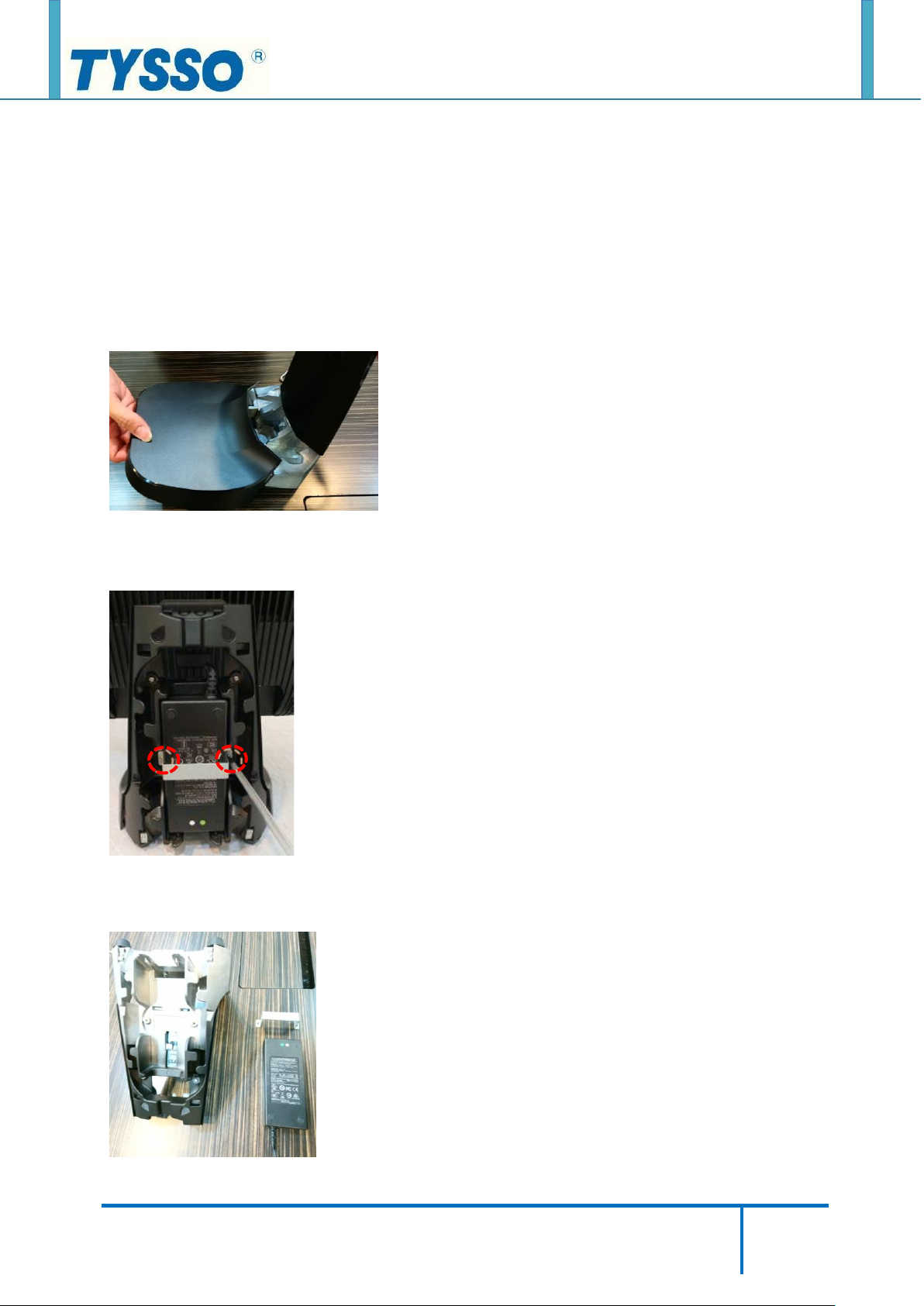
Remove the Power Adapter from the Base Unit
The base unit may need maintenance during a certain operation time.
For parts replacement, please purchase the service parts from manufacturer or authorized
distributer only.
①. Remove the base cover.
②. Loosen two securing screws (red dotted lines) of the metal bracket.
③. Remove the adapter.
Page 18
Copyright © 2019 Fametech Inc. All Rights Reserved.
All other brands, product names, company names, trade names, trademarks and service marks used
herein are the property of their respective owners.
18
Disassemble the POS Unit (with Motherboard Set)
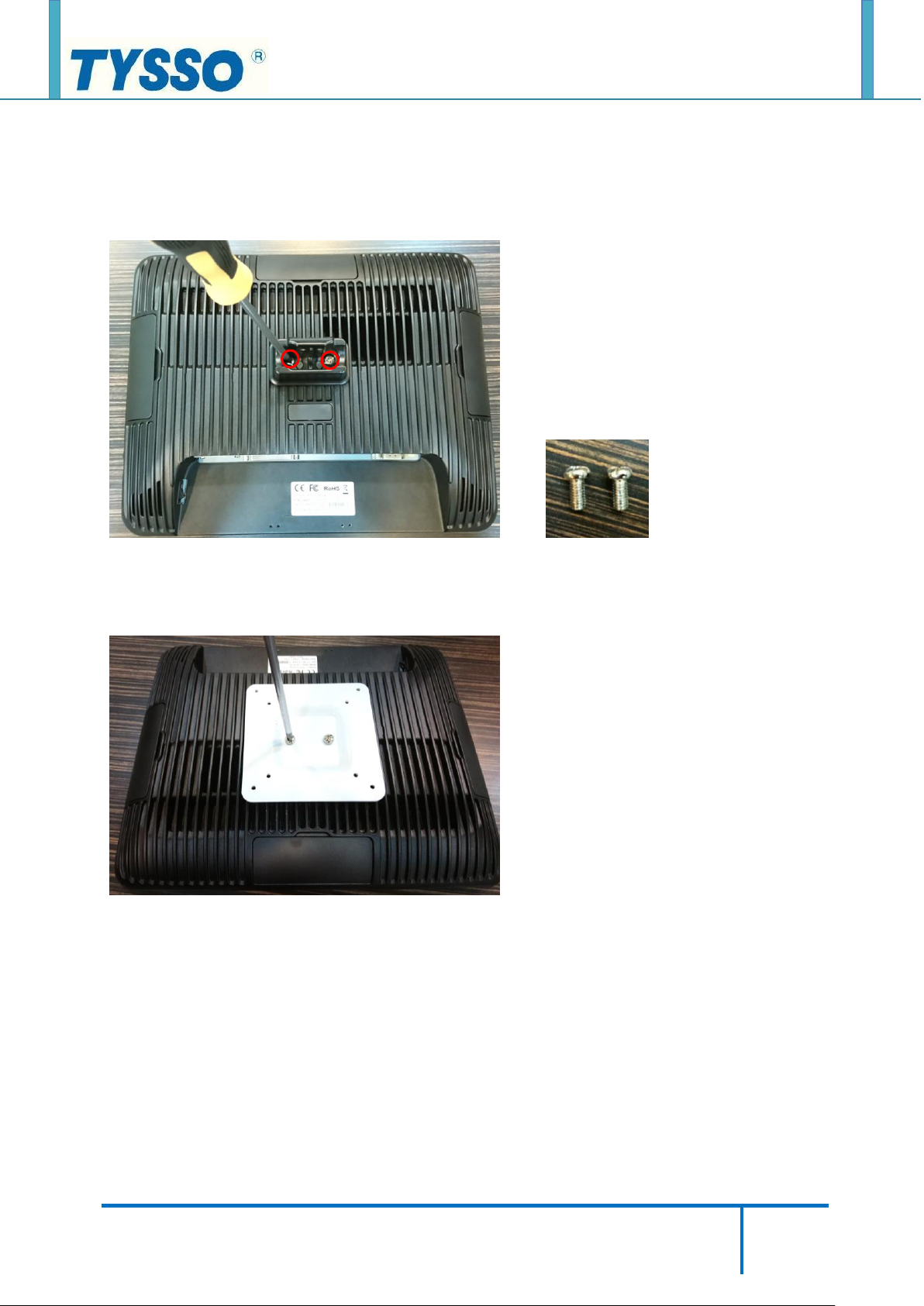
1. Remove the Back Cover of the POS Unit
①. Loosen two securing screws from the holder arm.
Note:
The holder arm can be replaced by VESA Mount bracket.
Page 19

Copyright © 2019 Fametech Inc. All Rights Reserved.
All other brands, product names, company names, trade names, trademarks and service marks used
herein are the property of their respective owners.
19
Slide Lock
②. Push upward to release two slide locks (left and right) on the back of the POS unit.
③. Lift the panel unit form the back cover.
④. Pull up the panel unit from the back cover.
Page 20

Copyright © 2019 Fametech Inc. All Rights Reserved.
All other brands, product names, company names, trade names, trademarks and service marks used
herein are the property of their respective owners.
20
2. Remove the RAM Module
①. Release the latches on the two sides of the RAM module slot.
②. Pull and remove the module out of the slot with care.
To Replace or Re-Install the RAM Module:
Install the RAM Module to the RAM Module slot.
Press the module until the two latches tighten RAM Module and firmly installed.
Note:
Store the RAM Module in a secure location for further use.
Page 21

Copyright © 2019 Fametech Inc. All Rights Reserved.
All other brands, product names, company names, trade names, trademarks and service marks used
herein are the property of their respective owners.
21
3. Remove the CPU
①. Depress the CPU socket retainer lever and slightly pull the lever outward (away from the
CPU) to free the lever from its retaining clip.
②. When you have released the lever from the retaining clip, lift the lever to its fully open
position. Lift the unhinged side of the CPU socket retainer to its fully open position.
③. Grasp the notched edges of the CPU PCB and lift it out of the socket.
Page 22

Copyright © 2019 Fametech Inc. All Rights Reserved.
All other brands, product names, company names, trade names, trademarks and service marks used
herein are the property of their respective owners.
22
4. Disconnect the HDD/SSD Drive Bracket and Cable from the Modular Motherboard
①. Use a screw driver to loosen the securing screw on the HDD bracket.
②. Pull out the HDD.
③. Loosen three securing screws to remove the HDD fixed bracket.
Page 23

Copyright © 2019 Fametech Inc. All Rights Reserved.
All other brands, product names, company names, trade names, trademarks and service marks used
herein are the property of their respective owners.
23
power cable
SATA cable
④. Remove the HDD Connector (green marks) from the metal HDD slot.
⑤. Disconnect the SATA cable and power cable from the motherboard.
Note:
Store the RAM Module in a secure location for further use.
If there is a cable binder on the HDD cable, cut the cable binger and disconnect the HDD
cable from the motherboard.
Store the HDD cable in a secure location for further use.
Remember to use a new cable binder to arrange and re-tighten the cables on the
Motherboard Set when the maintenance is completed.
Page 24

Copyright © 2019 Fametech Inc. All Rights Reserved.
All other brands, product names, company names, trade names, trademarks and service marks used
herein are the property of their respective owners.
24
5. Disconnect the Wi-Fi Module
①. Use a tweezer to remove two antenna PCBs (red marks) on both sides and disconnect
two cables (yellow dotted lines) from Wi-Fi card.
②. Use a tweezer to remove the spacer support.
③. Remove the Wi-Fi Module.
Page 25

Copyright © 2019 Fametech Inc. All Rights Reserved.
All other brands, product names, company names, trade names, trademarks and service marks used
herein are the property of their respective owners.
25
6. Disconnect the Dual USB Cable
①. Loosen two securing screws of the I/O Bracket.
②. Disconnect the USB Cable from the motherboard.
Page 26

Copyright © 2019 Fametech Inc. All Rights Reserved.
All other brands, product names, company names, trade names, trademarks and service marks used
herein are the property of their respective owners.
26
7. Disconnect the LPT Cable
①. Disconnect two hexagonal copper columns from the I/O bracket.
②. Disconnect the LPT cable from the motherboard.
Page 27

Copyright © 2019 Fametech Inc. All Rights Reserved.
All other brands, product names, company names, trade names, trademarks and service marks used
herein are the property of their respective owners.
27
power switch connector
Side USB connector
LED indicator connector
VGA connector
Touch Controller connector
Side USB connector
LVDS connector
Backlight connector
8. Disconnect all the Cables from the Motherboard
①. Cables on the left side of the motherboard, from top to bottom respectively are:
power switch cable, two side USB cables, and LED indicator cable.
②. Cables on the top side of the motherboard, from left to right respectively are:
VGA cable, Touch Controller cable, side USB cable, LVDS cable, Backlight cable.
Page 28

Copyright © 2019 Fametech Inc. All Rights Reserved.
All other brands, product names, company names, trade names, trademarks and service marks used
herein are the property of their respective owners.
28
9. Remove the Touch Controller Board and Cable
Remove the Projected Capacitive Controller and Cable
①. Tear off the sticker
②. Open the flip-lock connector and remove the Touch FFC.
Page 29

Copyright © 2019 Fametech Inc. All Rights Reserved.
All other brands, product names, company names, trade names, trademarks and service marks used
herein are the property of their respective owners.
29
③. Loosen four securing screws
④. Disconnect the touch controller cable from the motherboard.
Page 30

Copyright © 2019 Fametech Inc. All Rights Reserved.
All other brands, product names, company names, trade names, trademarks and service marks used
herein are the property of their respective owners.
30
Remove the Resistive Controller and Cable
①. Unplug the Touch FFC.
②. Disconnect the touch controller cable from the motherboard.
Page 31

Copyright © 2019 Fametech Inc. All Rights Reserved.
All other brands, product names, company names, trade names, trademarks and service marks used
herein are the property of their respective owners.
31
③. Loosen two securing screws of the touch controller board.
Page 32

Copyright © 2019 Fametech Inc. All Rights Reserved.
All other brands, product names, company names, trade names, trademarks and service marks used
herein are the property of their respective owners.
32
10. Remove the Motherboard
①. Loosen four hex standoff screws on the I/O bracket.
②. Unplug the speaker cable (yellow dotted line) from the motherboard.
③. Loosen four securing screws on the motherboard and remove the board.
Page 33

Copyright © 2019 Fametech Inc. All Rights Reserved.
All other brands, product names, company names, trade names, trademarks and service marks used
herein are the property of their respective owners.
33
Backlight cable
LVDS cable
11. Disconnect the Backlight and LVDS Cable
①. Tear off the acetate tape.
②. Unplug the Backlight cable (left) and LVDS cable (right).
Page 34

Copyright © 2019 Fametech Inc. All Rights Reserved.
All other brands, product names, company names, trade names, trademarks and service marks used
herein are the property of their respective owners.
34
12. Remove the Speaker
①. Loosen two securing screws of the speaker and remove it.
13. Remove the LED Cable and the Power Switch
Tips:
Use a needle nose pier to press the two sides of the power switch; and push to remove from
the metal bracket.
Page 35

Copyright © 2019 Fametech Inc. All Rights Reserved.
All other brands, product names, company names, trade names, trademarks and service marks used
herein are the property of their respective owners.
35
14. Remove the Metal Bracket of Bottom I/O Port
①. Use a screw driver to loosen three securing screws of the metal bracket from the Panel
Unit.
Page 36

Copyright © 2019 Fametech Inc. All Rights Reserved.
All other brands, product names, company names, trade names, trademarks and service marks used
herein are the property of their respective owners.
36
15. Remove the LCD Bracket
①. Loosen fourteen securing screws and remove the latches.
②. Loosen four securing screws
Page 37

Copyright © 2019 Fametech Inc. All Rights Reserved.
All other brands, product names, company names, trade names, trademarks and service marks used
herein are the property of their respective owners.
37
③. Detach the Bezel and LCD panel.
④. Loosen two securing screws on both left and right sides of the LCD chassis.
⑤. Detach the LCD Panel and LCD chassis.
Page 38

Copyright © 2019 Fametech Inc. All Rights Reserved.
All other brands, product names, company names, trade names, trademarks and service marks used
herein are the property of their respective owners.
38
Remove the 2nd HDD/SSD Drive
1. Remove the 2nd HDD/SSD Drive from the Base (Quick Detach)
①. Remove the base cover
②. Pull out the 2nd HDD/SSD Drive
③. Loosen four screws on the 2nd HDD/SSD Drive
Page 39

Copyright © 2019 Fametech Inc. All Rights Reserved.
All other brands, product names, company names, trade names, trademarks and service marks used
herein are the property of their respective owners.
39
2. Remove the SATA Extended Cable of the 2nd HDD/SSD
①. Lay the POS unit upside down then unplug the SATA cable and power cord.
②. Remove the rear cover and top cover of the base unit.
Page 40

Copyright © 2019 Fametech Inc. All Rights Reserved.
All other brands, product names, company names, trade names, trademarks and service marks used
herein are the property of their respective owners.
40
③. Loosen two hex socket head cap screws then detach the panel unit from the stand.
④. Remove the base cover.
⑤. Loosen two securing screws (red dotted lines) from the metal bracket.
Page 41

Copyright © 2019 Fametech Inc. All Rights Reserved.
All other brands, product names, company names, trade names, trademarks and service marks used
herein are the property of their respective owners.
41
⑥. Remove the adapter.
⑦. Loosen two securing screws to remove the SATA extended cable
Page 42

Copyright © 2019 Fametech Inc. All Rights Reserved.
All other brands, product names, company names, trade names, trademarks and service marks used
herein are the property of their respective owners.
42
1st HDD/SSD power cable
SATA cable
2nd HDD/SSD power cable
SATA cable
⑧. Unplug the power cable and SATA cable form the motherboard.
⑨. Loosen two securing screws on the 2nd HDD/SSD extended board and remove the board.
Page 43

Copyright © 2019 Fametech Inc. All Rights Reserved.
All other brands, product names, company names, trade names, trademarks and service marks used
herein are the property of their respective owners.
43
Application Programs
BIOS Setting and CMOS Clear
1. BIOS common functions
BIOS version: TP66BM12 (date: 02/06/2018)
①. POS status when the power is reinserted
[Tab bar] Advanced →Power Management →Restore AC Power Loss
˙Last State
˙Always On
˙Always Off (default)
②. COM1~2 power supply setting
[Tab bar] Advanced →Super IO Configuration →[*Active*] Serial Port 1~2 →Mode
˙RI# (default)
˙5V
˙12V
COM3~4 power supply setting from motherboard jumper (RI default).
Page 44

Copyright © 2019 Fametech Inc. All Rights Reserved.
All other brands, product names, company names, trade names, trademarks and service marks used
herein are the property of their respective owners.
44
COM5 default at +5V, COM6 fix at +12V.
③. Boot sequence
[Tab bar] Boot →Boot Option Priorities
˙Boot Option #1
˙Boot Option #2
④. Restore BIOS item to factory default setting
[Tab bar] Save & Exit →Restore Defaults
Page 45

Copyright © 2019 Fametech Inc. All Rights Reserved.
All other brands, product names, company names, trade names, trademarks and service marks used
herein are the property of their respective owners.
45
1 2 3
1-2 close: normal
2-3 close: clear CMOS
lithium battery plug
2. CMOS clear (reply the BIOS initial preset)
Step1. Remove the AC power line.
Step2. Set the jumper to pin 2-3 close.
Step3. Wait for five seconds.
Step4. Set the jumper to pin 1-2 close.
Step5. Power in the AC.
Page 46

Copyright © 2019 Fametech Inc. All Rights Reserved.
All other brands, product names, company names, trade names, trademarks and service marks used
herein are the property of their respective owners.
46
The controller is automatically detected
Touch Utility Setting
1. Projected capacitive touch
Please refer to the following file to install the utility.
"TP-2515_TP-8515_TP-7715_Touch Driver Installation_TYSSO_20180820.pdf"
①. Double click the icon to access the utility.
②. The menu will show the controller name " ILI25100CN150O01".
Page 47

Copyright © 2019 Fametech Inc. All Rights Reserved.
All other brands, product names, company names, trade names, trademarks and service marks used
herein are the property of their respective owners.
47
③. The function setting will take effect when the program is opened; the default is "OFF"
→ If you don't open this program is still working.
④. Sound setting.
Page 48

Copyright © 2019 Fametech Inc. All Rights Reserved.
All other brands, product names, company names, trade names, trademarks and service marks used
herein are the property of their respective owners.
48
⑤. Adjustable when the edge of the screen lacks sensitivity.
⑥. Mapping area setting.
Page 49

Copyright © 2019 Fametech Inc. All Rights Reserved.
All other brands, product names, company names, trade names, trademarks and service marks used
herein are the property of their respective owners.
49
The controller is automatically detected
2. Resistive touch
Please refer the following file to install the utility.
"TP-2515_TP-8515_TP-7715_Touch Driver Installation_TYSSO_20180820.pdf"
①. Double click the icon to access the utility.
②. The menu will show the controller name “HID TOUCH0”.
Resistive touch panel requires calibration to maintain linearity.
Page 50

Copyright © 2019 Fametech Inc. All Rights Reserved.
All other brands, product names, company names, trade names, trademarks and service marks used
herein are the property of their respective owners.
50
③. Perform 9 point calibration.
④. Mouse setting.
Page 51

Copyright © 2019 Fametech Inc. All Rights Reserved.
All other brands, product names, company names, trade names, trademarks and service marks used
herein are the property of their respective owners.
51
⑤. Sound setting.
Page 52

Copyright © 2019 Fametech Inc. All Rights Reserved.
All other brands, product names, company names, trade names, trademarks and service marks used
herein are the property of their respective owners.
52
Specifications
Motherboard Layout
Page 53

Copyright © 2019 Fametech Inc. All Rights Reserved.
All other brands, product names, company names, trade names, trademarks and service marks used
herein are the property of their respective owners.
53
Exploded View
Page 54

Copyright © 2019 Fametech Inc. All Rights Reserved.
All other brands, product names, company names, trade names, trademarks and service marks used
herein are the property of their respective owners.
54
No
Item
Description
1a
P-CAP. TP
Front
bezel
set
Projected capacitive touch panel
PN: BP-TOUCH-204-0031-07
Touch panel + front bezel
finished product,
1. P-CAP (a)
PN: SEMI-TP-7715-TP-P-KIT-x
2. RES (b)
PN: SEMI-TP-7715-TP-R-KIT-x
1b
RES. TP
Resistive touch panel
PN: BP-TOUCH-104-0029-07
2
Adhesive
3M double adhesive tape +
mylar
PN:
A-PAP-TP-7715-BEZEL-SET
3
Bezel
Front bezel
PN: JP-TP-7715-F-BEZEL-x
4
LCD panel
15” TFT-LCD module
PN: BP-PANEL-LVDS-15INCH
5
LCD chassis
LCD panel chassis
PN: KP-TP-7715-LCD-BRKT
6
Side latch
Side latch (2PCS used)
PN: KP-TP-7715-SNAP-LATCH-BRKT
7a
RES. touch CB
Resistive touch controller board
PN: BP-PART-THPCBA-USB-R5W-3000U
7b
P-CAP touch CB
Projected capacitive touch controller board
PN: BP-PART-THPCBA-PCAP-15INCH-TOC
8
Upper latch
Upper latch (2PCS used)
PN: KP-TP-7715-FRONT-T-SNAP-BRKT
9
Motherboard
6th/7th Gen. core-i H110 motherboard, mini-ITX
PN: BP-TPM-6600-AA
6th/7th Gen. core-i Q170 motherboard, mini-ITX
PN: BP-TPM-6610-AA
CPU
Skylake CPU i3 6100TE
PN: BP-CPU-CORE-I3-6100TE
Skylake CPU i5 6500TE
PN: BP-CPU-CORE-I5-6500TE
Skylake CPU i7 6700TE
PN: BP-CPU-CORE-I7-6700TE
Kabylake CPU i3 7101TE
PN: BP-CPU-CORE-I3-7101TE
Kabylake CPU i5 7500T
PN: BP-CPU-CORE-I5-7500T
Kabylake CPU i7 7700T
PN: BP-CPU-CORE-I7-7700T
RAM
DDR4 RAM SODIMM 260pin
PN: BP-RAM-DDR4-4GB
PN: BP-RAM-DDR4-8GB
Parts Description
Page 55

Copyright © 2019 Fametech Inc. All Rights Reserved.
All other brands, product names, company names, trade names, trademarks and service marks used
herein are the property of their respective owners.
55
PN: BP-RAM-DDR4-16GB
10
Speaker
Speaker 8 ohms 2watts with cable
PN: NS-POS-1000B-HIT-4028-82280-X1
11
Power switch
Power switch with cable
PN: CP-CBL-POP-950-PSW
(12)
2nd HDD/SSD board
(optional)
2nd HDD/SSD transfer PCBA + fixed bracket (optional)
PN: KP-TP-7715-SSD-BD-BRKT
PN: BP-PCBA-TH-100S-V0
13
Under latch
Under latch (3PCS used)
PN: KP-TP-7715-FRONT-D-SNAP-BRKT
14a
IO bracket with dual
USB
IO bracket with dual USB (standard)
PN: KP-TP-7715-IO-BRKT-DUALUSB
14b
IO bracket with
power USB
IO bracket with power USB (optional)
PN: KP-TP-7715-IO-BRKT-PWRUSB
15
Upper snap
Upper snap (2PCS used)
PN: KP-TP-7715-REAR-T-SNAP-BRKT
16
Side snap fixed, left
Side button snap fixed holder + spring, left
PN: JP-TP-7715-SNAP-BTN-FIX-L-x
PN: KP-TP-7715-SNAP-SPRING
17
Side snap fixed, right
Side button snap fixed holder + spring, right
PN: JP-TP-7715-SNAP-BTN-FIX-R-x
PN: KP-TP-7715-SNAP-SPRING
18
Side snap, left
Side button activity snap, left
PN: JP-TP-7715-SNAP-BTN-L-x
19
Side snap, right
Side button activity snap, right
PN: JP-TP-7715-SNAP-BTN-R-x
20
HDD fixed bracket
2.5” HDD fixed bracket
PN: KP-TP-7715-HDD-FIX-BRKT
21
HDD bay
2.5” HDD bay
PN: KP-TP-7715-HDD-BRKT
22
1st HDD / SSD
1st 2.5” HDD / SSD
PN:BP-HDD-500GB-5400(7200), BP-SSD-64GB(128GB)(256GB)
23
Heat pipe module
Heat pipe module, copper block & pipe x2
PN: IA-PAP-TP-7715-HEATPIPE-MOUDLE
24
Mylar
Heat pipe copper block mylar
PN: IA-PAP-TP-7715-HEATPIPE-MYLAR
Page 56

Copyright © 2019 Fametech Inc. All Rights Reserved.
All other brands, product names, company names, trade names, trademarks and service marks used
herein are the property of their respective owners.
56
25
Heat pipe bracket
Heat pipe module bracket (5PCS used)
PN: KP-TP-7715-HEATPIPE-BRKT
26
Under snap
Under snap
PN: KP-TP-7715-REAR-D-SNAP-BRKT
27
Left cover
Rear left cover
PN: JP-TP-7715-R-LEFT-COVER-x
28
Rear cover
Aluminum die casting rear cover
PN: KP-TP-7715-REAR-COVER-x
29
Top cover
Rear top cover
PN: JP-TP-7715-R-TOP-COVER-x(-TYS)
30
Right cover
Rear right cover
PN: JP-TP-7715-R-RIGHT-COVER-x
31
Stand
Aluminum die casting stand + metal sheet(2PCS used)
PN: KP-TP-7715-STAND-x
PN: KP-TP-7715-MAGNET-METAL
32
Base
Aluminum die casting base
PN: KP-TP-7715-BASE
33
ARM
Holder arm
PN: KP-TP-7715-HOLDER-ARM-x
34
Hinge
Arm hinge
PN: KP-TP-7715-HINGE-75KG
35
Stand front cover
Stand front cover
PN: JP-TP-7715-STAND-FRONT-COVER-x
36
Stand rear cover
Stand rear cover + magnet (2PCS used)
PN: JP-TP-7715-STAND-REAR-COVER-x
PN: KP-TP-7715-MAGNET
37
Stand top cover
Stand top cover with rubber
PN: SEMI-TP-7715-STAND-T-COV-xx
38
Stand base cover
Stand base cover
PN: JP-TP-7715-STAND-BASE-COVER-x
39a
Adapter 90W
Adapter 90watts 12V / 7.5A
PN: DP-PWRC-EA10951F-ED-300MM
39b
Adapter 150W
Adapter 150watts 12V / 12.5A
PN: DP-PWRC-EA11701E-ED
40a
Adapter bracket
Adapter bracket
PN: KP-TP-7715-PWR-BRKT
Page 57

Copyright © 2019 Fametech Inc. All Rights Reserved.
All other brands, product names, company names, trade names, trademarks and service marks used
herein are the property of their respective owners.
57
(41)
2nd HDD bay
2nd 2.5” HDD bay (optional)
PN: KP-TP-7715-HDD-BAY
(42)
2nd HDD / SSD
2nd 2.5” HDD / SSD
PN:BP-HDD-500GB-5400(7200), BP-SSD-64GB(128GB)(256GB)
 Loading...