

Page 1
PRP-080
THERMAL RECEIPT PRINTER
User's Manual
Specifications subjects to
change without notice
Page 2

-1-
Contents
1. General Information
2. Quick Start
3. Printer Interface and Connection
4. Configuration
5. Safety and Maintenance
Appendix (A) Specifications
2.1) Unpacking & Parts Identification.............................. 3
2.2) Loading the Paper Roll
3.1) Connecting the Interface Cable
3.2) Connecting to a Cash Drawer
3.3) Connecting the AC Adapter
4.1) Printer Status (Red LED)
4.2) DIP Switch Settings
4.3) Printer Self Test
5.1) Safety Information
5.2) Periodical Cleaning
5.3) Preventing Paper Jams
5.4) Fixing Paper Jam
...................................................... 2
...............................................4
................................. 6
.................................... 6
........................................7
.......................................... 8
................................................... 9
......................................................... 9
.................................................. 10
................................................. 11
............................................. 11
..................................................... 12
.............................................. 14
.......................................... 16
.......................................... 21
Appendix (B) Configurations
Appendix (C) Commands List
Page 3
-3--2-
1. General Information
Models
Main Features
PRP-080SC (serial interface, with auto-cutter)
PRP-080PC (parallel interface, with auto-cutter)
PRP-080SN (serial interface, without auto-cutter)
PRP-080PN (parallel interface, without auto-cutter)
220mm/s maximum print speed.
High reliability due to a stable mechanism.
Command protocol is based on the ESC/POS standard.
Various layouts are possible by using page mode (#).
Characters can be scaled up to 64 times as large as the
standard size.
Repeated operation and copy printing are possible by using
macro definitions.
Character font size (12 24 font or 24 24 font) can be
selected by using a command.
Easy paper-roll installation.
Equipped with an auto-cutter.
The printer allows easy maintenance for tasks such as head
cleaning.
Two different print densities can be selected by DIP
switches.
The built-in interface provides control capability for one
cash drawer.
1. High speed printing:
2. Application Software:
3. Printer Handling:
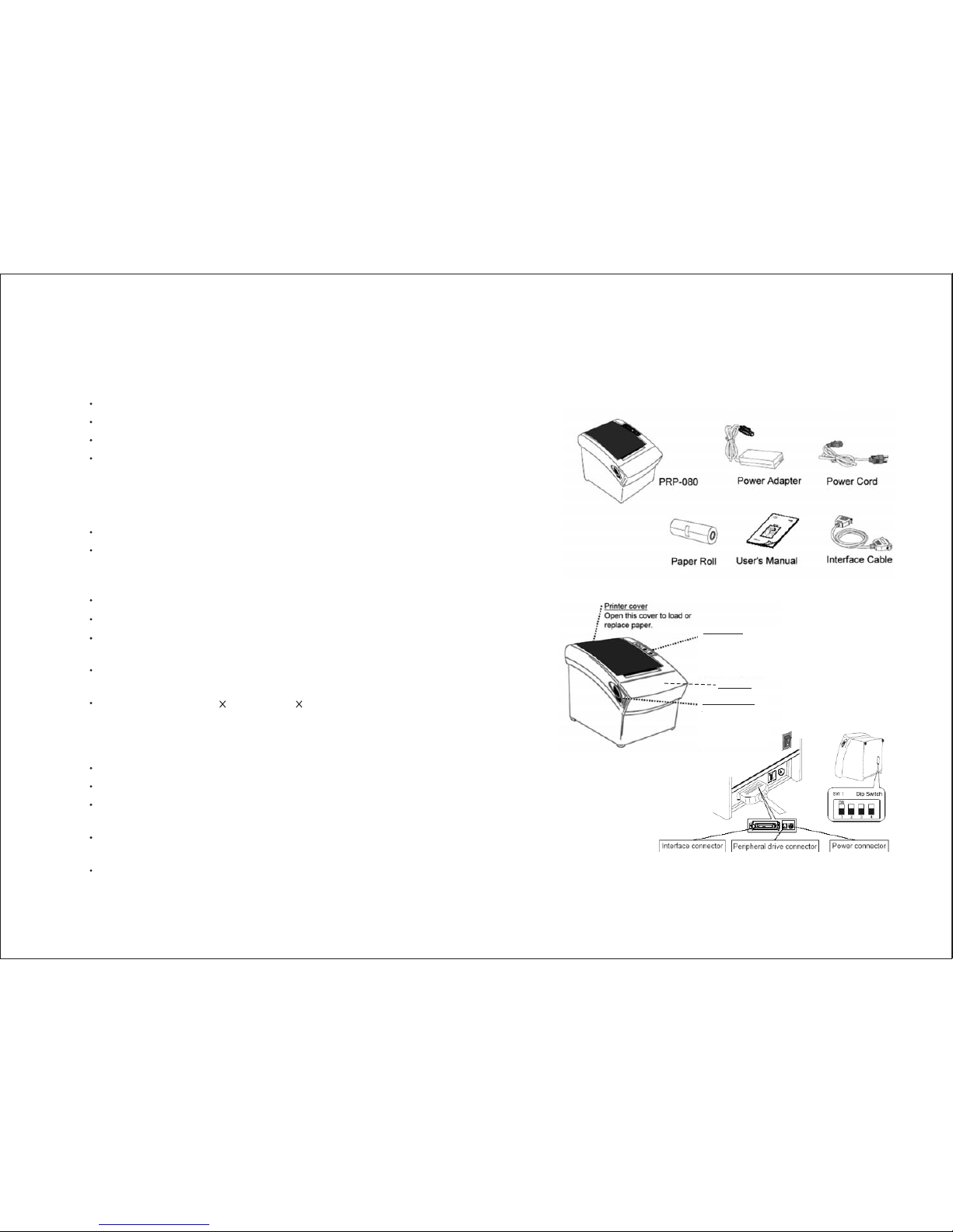
Front cover
Control panel
Features LED indicators
to indicate printer
status and buttons to
operate the printer.
Cover Open lever
Pull this lever in the
direction of the
arrow to open the
printer cover.
Connects to peripheral
units such as cash
drawers, etc.
Do not connect this toa
telephone line.
For connection to a
host computer.
For connection of
the AC adapter.
Never unplug the
AC adapter while
the printer is on.
2. Quick Start
2.1) Unpacking & Parts Identification
a. Inside the Package:
b. Parts Identification:
Page 4
-5--4-
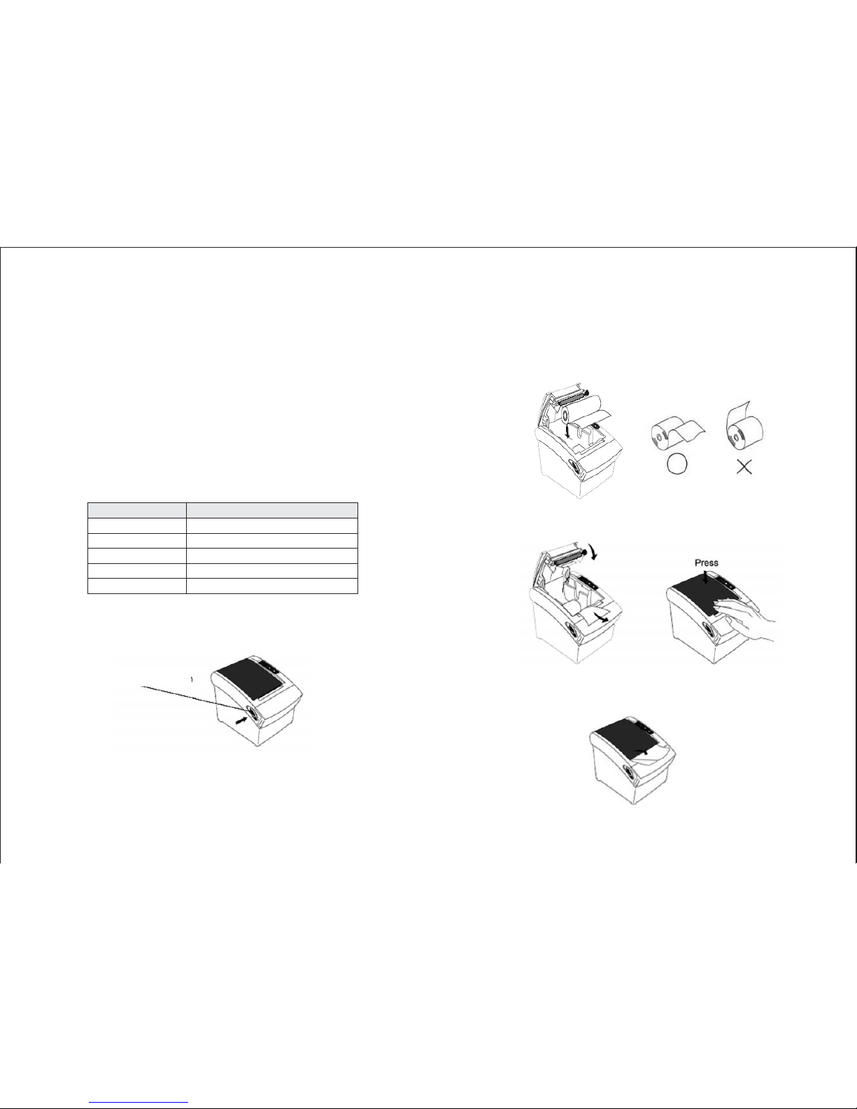
2.2) Loading the Paper Roll
a. Make sure that the paper roll matches the printer's
specification. Do not use paper rolls that have the paper
glued to the core because the printer cannot detect the
paper end correctly. Important: The printing quality and
lifespan of the thermal head cannot be guaranteed if any
paper other than that recommended is used. Thus, the
warranty will be voided automatically if any fault occurs
due to the use of wrong paper rolls.
b. Open the printer cover by pressing the Cover-Open level
Do not pull the cover open lever and open the
printer cover when printing is in progress.
Recommended Paper Rolls
Important:
Part Number
HPK-110
AF50KS-E
TF-50KS-E
PD-160R
F380
Manufacturer
Hansol Patech Co. Ltd.
JUJO Paper Co. Ltd.
Nippon Paper Industries Co. Ltd.
New Oji Paper Mfg. Co. Ltd.
Nansaki Specialty Papers Inc.
c. While observing the direction of the roll, set the paper roll
into the hollow, and pull out the leading edge of the paper
toward you as shown:
d. Close the cover: When closing the cover, press the center
of printer cover firmly to prevent paper miss-loading
e. Tear off the paper outside the cover as shown.
(If the printer is without auto-cutter)
Cover-Open lever
Page 5
-7--6-
3.
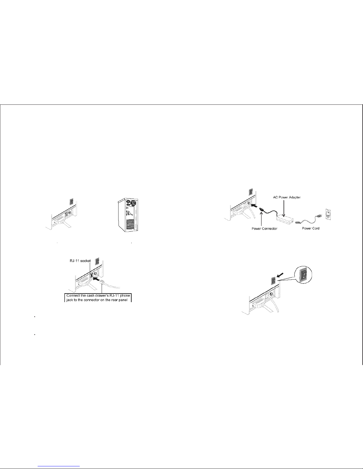
3.1) Connecting the Interface Cable
3.2) Connecting to a Cash Drawer
a. Before connecting/disconnecting the interface cable,
make sure that power to the printer and all the devices
connected to the printer is turned off.
b. Connect the interface cable to the connector on the rear
panel of the printer.
c. In the case of a serial interface, tighten the connector
screws. In the case of a parallel interface, fasten the
connector clasps.
Make sure that the printer is turned off and unplugged from
the AC outlet and that the computer is turned off before
making connections.
Do not connect a telephone line into the RJ-11 socket.
Failure to observe this may result in damage to the printer.
Important:
3.3) Connecting the AC Adapter
a. Connect the AC power cord to the inlet of AC adapter,
and then connect the power cord plug to a suitable
electrical outlet.
b. Connect the adapter cable to power connector of printer;
make sure the printer power switch is OFF before making
any connections.
DO NOT USE ANY AC POWER ADAPTERS
OTHER THAN SPECIFIED.
c. Set the power switch as shown. The POWER LED on the
control panel will light up.
CAUTION:
Printer Interface and Connection
Plug the cable connector securely
into the printer's interface connector.
Attach the other end of the
cable to the computer
Page 6
-9--8-
4. Configuration
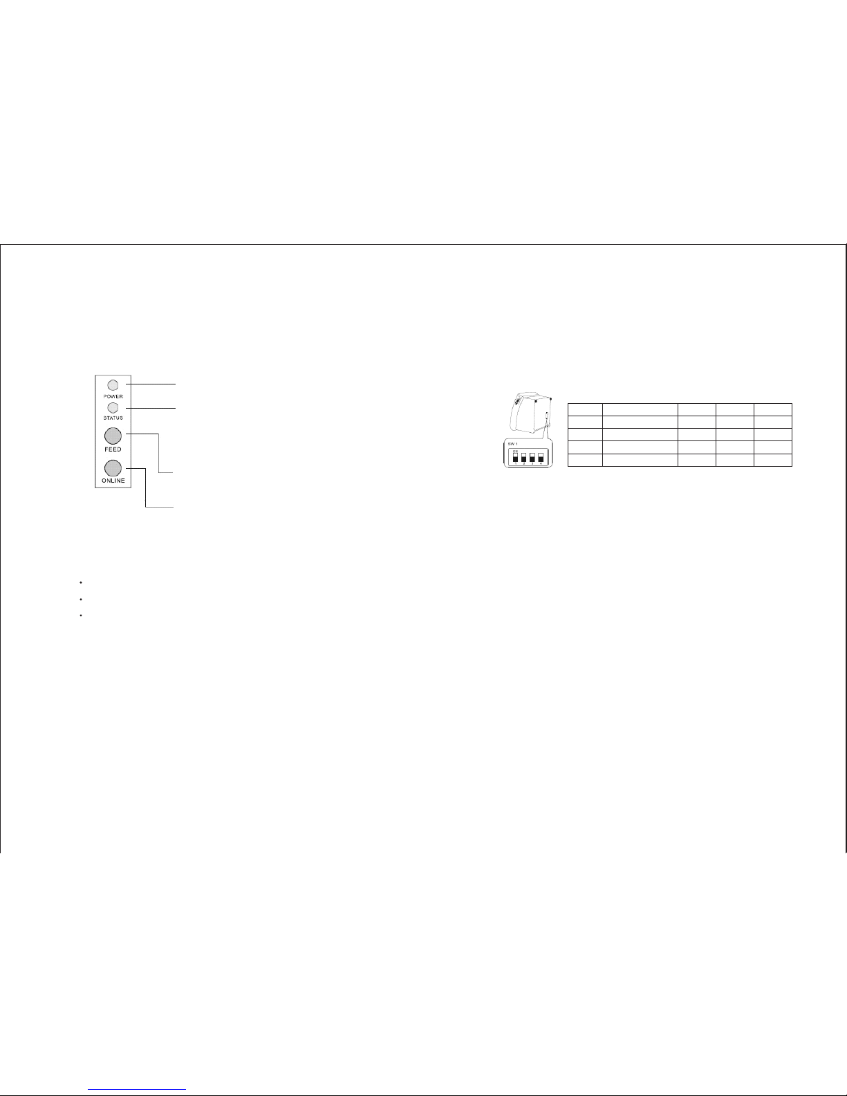
Printer Control Panel & Status Indication
4.1) Printer Status (Red LED)
Red light ON: Indicates that the printer is online.
Red light OFF: Indicates that the printer is offline.
Red light flashes: Indicates the printer error(s) such as out
of paper, paper jammed, or printer cover is not closed
properly.
4.2) DIP Switch Settings
4.3) Printer Self Test
The DIP switch panel is located at bottom of the printer as
shown:
Before configure the DIP switch settings, please first
turn the printer power off and remove the paper roll.
(*) Baud Rate is only available for serial interface models.
This is to test whether the printer is working properly or not
and also checks the printing quality, firmware version, and
DIP switch settings
1. Hold the ONLINE button first and then turn on the power
at the same time, release the button after around 1 second.
2. If the printer is working properly, it should then
automatically print the self-testing result that indicating
the firmware version number, printer connection type,
English alphanumeric characters, and few Chinese fonts.
3. The test print will be ended with the following message:
*** COMPLETED ***
The above procedure does not test parallel or serial
ports. Please use communication utility such as
Windows Hyper Terminal to test the printer
connection.
Switch Function ON OFF Default
1 Baud Rate (*) 38400 19200 OFF
2 Auto Cutter No Yes OFF
3 Color Deepness Deeper Normal OFF
4 Beep Yes No OFF
DIP Switch Functions:
Note:
Note:
(Blue LED) The POWER light is on whenever
the printer is on.
(Red LED) This indicates printer online/offline
status or an error
(Button) Press the FEED button to feed roll paper.
(Button) Press the ONLINE button to set printer
ONLINE/OFFLINE
Page 7

-11--10-
5. Safety and Maintenance
5.1) Safety Information
1. Do not touch the HEAD of printer with anything.
2. Do not touch the cutter blade.
3. Only use the power supply that is come along with the
printer.
4. Do not bend the power cord excessively or place any
heavy objects onto it.
5. When connecting or disconnecting the plug, always hold
the plug not the cord.
6. Use only approved accessories and do not try to
disassemble, repair or remodel it by yourself.
7. Do not let water or other objects in the printer.
8. Install the printer on the stable surface. Choose a firm,
level surface where the printer will not be exposed to
vibration.
9. Do not use the printer when it is out of order. This can
cause a fire or an electrocution.
10. Do not connect a telephone line into the peripheral drive
connector.(RJ-11 socket)
11. We recommend that you unplug the printer from the
power outlet whenever you do not plan to use it for long
periods.
5.2) Periodical Cleaning
5.3) Preventing Paper Jams
Printed characters may become partially unclear due to
accumulated paper dust and dirt. To prevent such a problem,
paper dust collected in the paper holder and paper transport
section and on the surface of the thermal head must be
removed periodically. Such cleaning is recommended to be
carried out once six month or one million lines.
To remove blackish dust collected on the surface of the
thermal head, wipe it with Isopropyl alcohol (IPA).
The thermal head is easy to damage, so clean it gently
with a soft cloth. Take sufficient care not to scratch it
when cleaning it.
Use a soft cloth to remove paper dust from the paper holder
and paper transport section.
The paper should not be touched during printing. Shift the
paper during paper ejection may cause a feed failure or
paper jam.
a. Cleaning the Thermal Head
Note:
b. Cleaning the Paper Holder
Page 8

-13--12-
5.4) Fixing Paper Jam
The Status LED (Red) on the printer control panel will flash
with beeps if paper is jammed. Please follow the below
instruction to remove paper jam.
a. Switch the printer power off.
b. Open the printer cover by pushing
the Cover-Open lever.
c. If the printer cover opens, removed
the jammed paper gently (
), and reinstall the paper roll.
d. , please restart the
printer by switching power off/on, and try again, if the
cover is still unable to open, please follow the instructions
below:
1) Set the printer power OFF
2) Slide off the front cover to
reveal the auto-cutter
3) Roll the little gear as
shown until the warning
beeps is stopped.
Since working on the cutter may be dangerous,
be sure to turn off the printer first.
Do not apply extreme force to open the front cover
to prevent damages to the cutter.
If the front cover will not open properly, please
contact your dealer.
take care not to touch the
printer head
If the printer cover will not open
Caution:
Note:
e. Return the cutter to its home-position and release or clean
out the jammed paper inside the front cover. Open the
printer cover, and then reinstall paper roll.
(Reinstall Paper Poll)
(Tear off the paper as shown)
Page 9

-15--14-
Appendix (A) Specifications
Print method
Max. label width
Character per line
Print head
Interfaces
Weight
Dimensions
Environment
Direct thermal
79.5mm 0.5mm
48 (Font A)Effective print width
72mm Print speed
220mm/sec.(max.) or 58 lines/sec.
576 dots/line or 8 dots/mm
0.125mm
100km
80 C
Dsub 25 pin female connector, 19200
or 38400 bps baud-rate, none parity, 8
data bits and 1 stop bit, supports
RTS/CTS & XON/XOFF protocol
36 pin Centronics connector. 8 bits
parallel, supports BUSY protocol
DC 24V/1A, 6 wires RJ-11 socket
1400g (without cable)
190mm(L) 145mm(W) 147mm(H)
0 ~ +45 C, 10%RH ~ 90%RH
-10 C ~ +50 C, 10%RH ~ 90%RH
+
Print density
Dot space
Print life
Halt-on protection
from over-heat
Serial port
Parallel port
Cash drawer port
Operating
Storage
o
oo
oo
xx
Power supply
Print font
Print commands
Paper adopted
Auto-Cutter
100V AC ~ 240V AC, 50 ~ 60 Hz
+24V DC/2.5A
12 24 dots, 1.25mm(W)
3.00mm(H)
24 24 dots, 3.00mm(W)
3.00mm(H)
ESC/POS print commands set
Direct thermal printing paper
79.5mm 0.5mm
83mm
53~60g/m
Life span: over 1,000,000 cuts
Input
Output
ASCII code
Graphic font
Paper width
Max. roll diameter
Paper thickness
xx
xx
+
2
Page 10

-17--16-
Appendix (B) Configurations
1. Interface
1.1 RS-232 serial interface
1.1.1 RS-232 Specifications
Data transmission: Serial
Synchronization: Asynchronous
Handshaking: DTR/DSR or XON/XOFF control
Signal levels: MARK =
-3 to -15V: Logic "1"/ OFF
SPACE =
+3 to +15V: Logic "0"/ ON
Baud rate: 19200bps ~ 38400bps
Data word length: 8 bits
Parity Settings: None
Stop bits: 1 or more
Connector: Female DSUB-25 pin connector
(printer side)
The data word length, baud rate, and parity
depend on the DIP switch settings.
The stop bit for the printer side is fixed to 1.
NOTES:
1.1.2 Switching between on-line and off-line
1.1.3 Serial interface connection example
The printer has an on-line/off-line button.
The printer goes off-line:
Between when the power is turned on (including reset
using the interface) and when the printer is ready to
receive data.
During the self-test.
When the cover is open.
During paper feeding using the paper feed button.
When the printer stops printing due to a paper-end (in
cases when an empty paper supply is detected by either
paper roll end detector or the paper roll near-end detector
with a printing halt feature by ESC c 4).
When a temporary abnormality occurs in the power
supply voltage.
When an error has occurred.
Host side Printer side
TXD ................................ RXD
DSR ................................ DTR
CTS ................................ RTS
RXD ................................ TXD
DTR ................................ DSR
FG ................................... FG
SG ................................... SG
Set the handshaking so that the transmit data can
be received. Transmit data to the printer after
turning on the power and initializing the printer.
NOTES:
Page 11
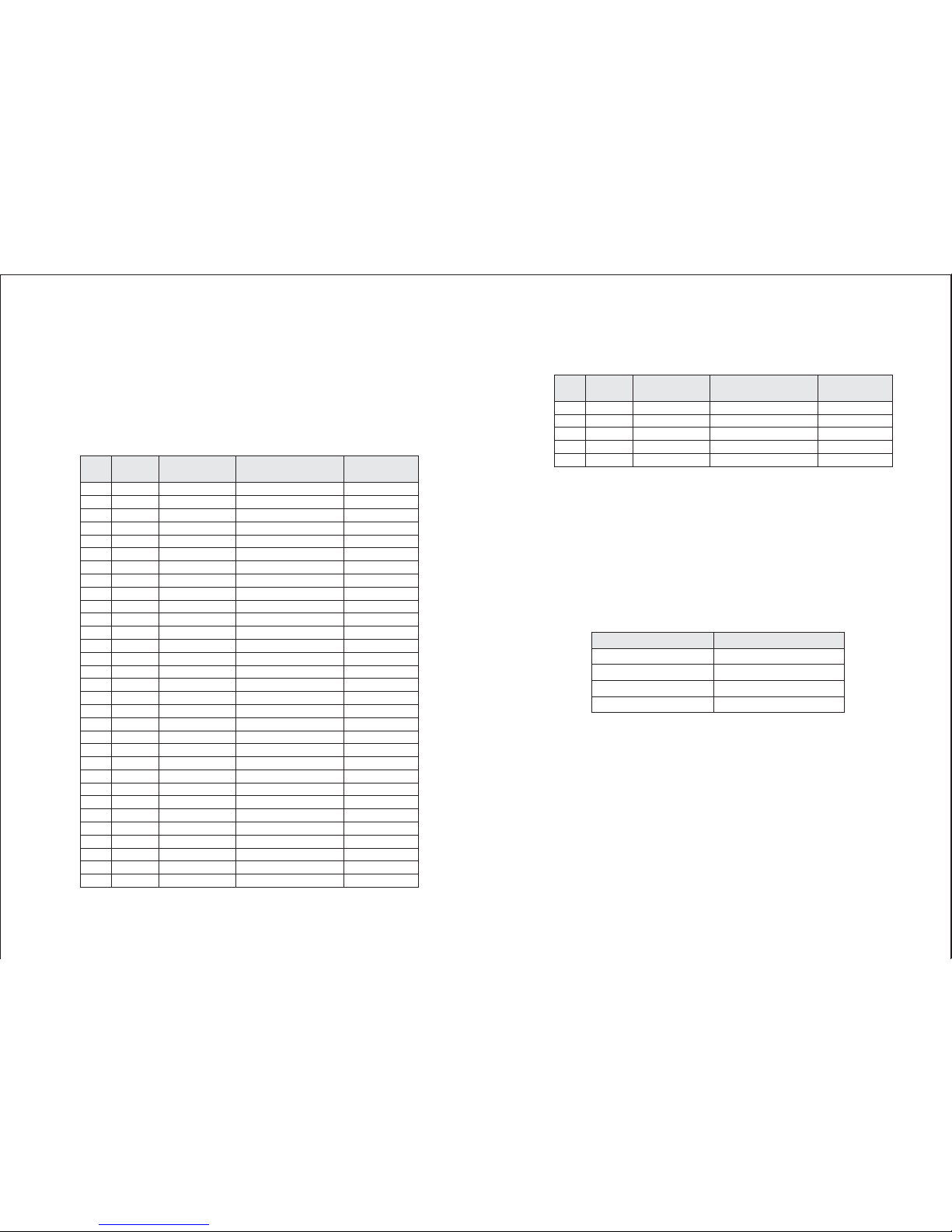
1.2 IEEE 1284 Bidirectional Parallel Interface
(Parallel Interface Specifications)
Copyright (C) 1993 by the Institute of Electrical and
Electronic Engineers, Inc.
Interface Pin Assignments for Each Mode
1 Host nStrobe HostClk HostClk
2 Host/Ptr Data0(LSB) Data0(LSB) Data0(LSB)
3 Host/Ptr Data1 Data1 Data1
4 Host/Ptr Data2 Data2 Data2
5 Host/Ptr Data3 Data3 Data3
6 Host/Ptr Data4 Data4 Data4
7 Host/Ptr Data5 Data5 Data5
8 Host/Ptr Data6 Data6 Data6
9 Host/Ptr Data7 (MSB) Data7(MSB) Data7(MSB)
10 Printer nAck PtrClk PtrClk
11 Printer Busy PtrBusy/Data3, 7 PtrBusy
12 Printer PError AckDataReq/Data2, 6 AckDataReq
13 Printer Select Xflag/Data1, 5 Xflag
14 Hostr nAutoFd HostBusy HostBusy
15 NC ND ND
16 GND GND GND
17 FG FG FG
18 Printer Logic-H Logic-H Logic-H
19 GND GND GND
20 GND GND GND
21 GND GND GND
22 GND GND GND
23 GND GND GND
24 GND GND GND
25 GND GND GND
26 GND GND GND
27 GND GND GND
28 GND GND GND
29 GND GND GND
30 GND GND GND
31 Host nInit nInit nInit
Pin Source Compatibility Nibble Mode Byte Mode
Mode
-19--18-
Pin Source Compatibility Nibble Mode Byte Mode
Mode
32 Printer nFault nDataAvail/Data0, 4 nDataAvail
33 GND ND ND
34 Printer DK_STATUS ND ND
35 Printer +5V ND ND
36 Host nSelectIn 1284-Active 1284-Active
*ND: Not Defined *NC: No Connect
2. Connectors
2.1 Interface Connectors
2.2 Power Supply Connector
2.3 Drawer Kick-out Connector
Refer to Interface and Connection section.
This connector is used to connect the printer to an
external power source.
1 +24 VDC
2 GND
3NC
Shell Frame GND
The pulse specified by ESC p or DLE DC4 is output to this
connector. The host can confirm the status of the input
signal by using the DLE EOT, GS a, or GS r commands.
1) Pin assignments: Refer to page 22
2) Connector model: Printer side: MOLEX 52065-6615 or
RJ-11 telephone jack
User side: 6-position 6-contact
(RJ-11 telephone jack)
Power Supply Connector Pin Assignments
Pin Number Signal Name
Page 12

-21--20-
Drawer Kick-out Connector Pin Assignments
Output signal:
Pin Number Signal Name Direction
1 Frame GND
2 GND
3NC
4 Drawer kick-out drive signal Output
5NC
6NC
Output voltage: Approximately 24 V
Output current: 1A or less
3. Drawer kick-out drive signal
Appendix (C) Commands List
Command Name
HT Horizontal tab
LF Print and line feed
CR Print and carriage return
ESC SP n Set right-side character spacing
ESC ! N Select print mode(s)
ESC $ nL nH Set absolute print position
ESC % n Select/cancel user-defined character set
ESC& yc 1c 2 Define user-defined characters
ESC * Select bit-image mode
ESC - Turn underline mode on/off
ESC 2 Select default line spacing
ESC 3 n Set line spacing
ESC ? N Cancel user-defined characters
ESC @ Initialize printer
ESC D Set horizontal tab positions
ESC G n Turn double-strike mode on/off
ESC J n Print and feed paper
ESC \ nL nH Set relative print position
ESCc 5n Enable/disable panel buttons
ESC d n Print and feed n lines
ESCp mt 1t 2 General pulse
GS* x y Define downloaded bit image
GS / m Print downloaded bit image
GS L nL nH Set left margin
GS V Cut paper
GS W Set printing area width
Command classification
Executing:Printer executes the command, which does not
then affect the following data.
Setting: Printer uses flags to make settings, and those
settings affect the following data.
 Loading...