

Page 1
Service Manual
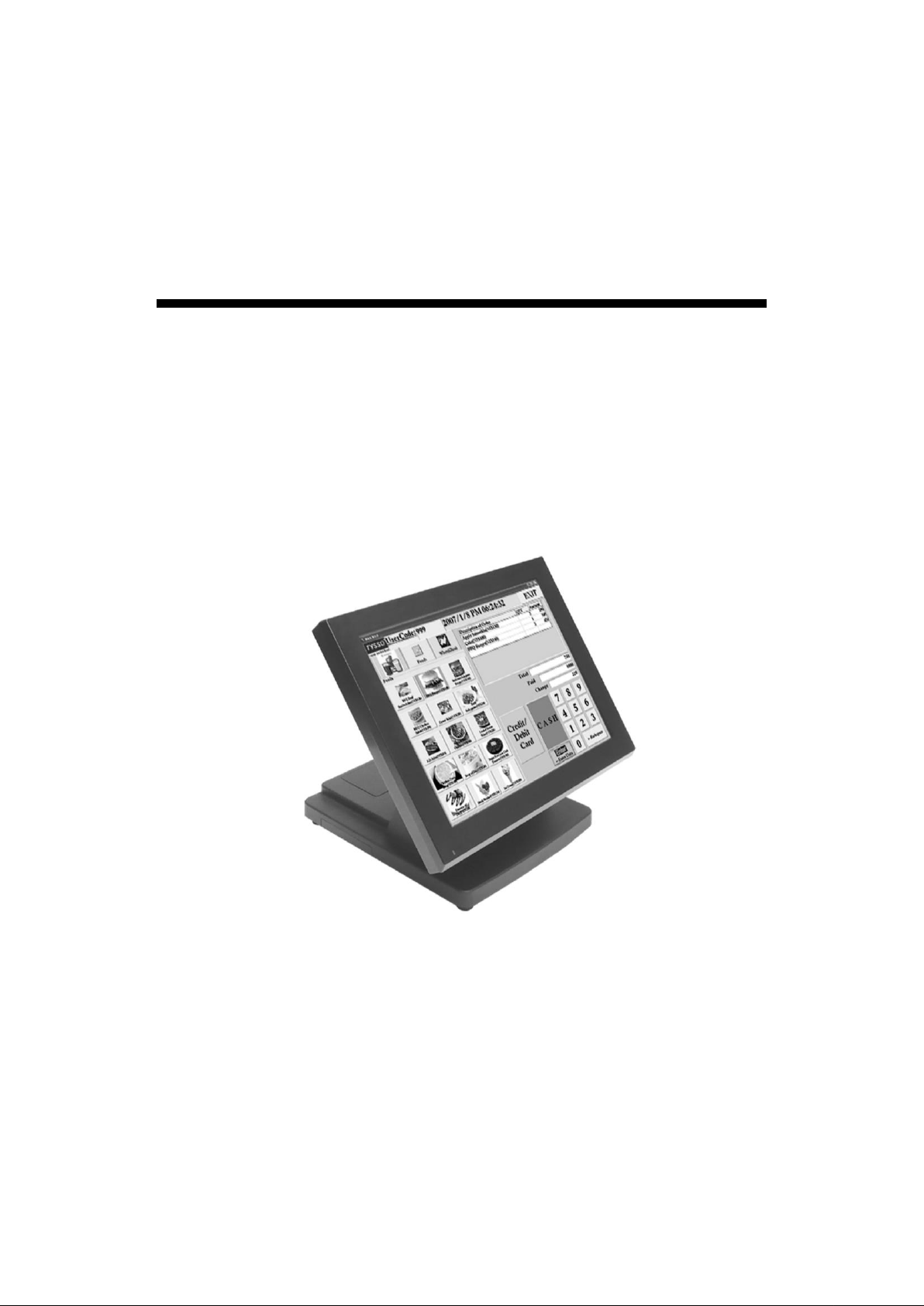
POS Peripheral Dock
PPD Series
PPD-1500 / PPD-1700
Ver.2.0
© Copyright Fametech Inc. (TYSSO) 2016
Page 2

- 1 -
Table of Contents
I Part List ......................................................................................................................... 2
A. Explode................................................................................................................. 2
B. Cables & Connectors ............................................................................................ 4
II System Disassembly .................................................................................................. 8
A. Separate the Monitor from the Base ................................ ..................................... 8
B. Disassemble Panel Kit .......................................................................................... 9
C. Disassemble Base Kit ........................................................................................ 16
Table of Figures
Figure 1 Explode of the System ............................................................................................ 2
Figure 2 Cables .................................................................................................................... 4
Figure 3 I/O Board ................................................................................................................ 5
Figure 4 Resistive Type Touch Control Board ....................................................................... 5
Figure 5 A/D Board (A) ................................................................ ......................................... 6
Figure 6 A/D Board (B) ................................................................ ......................................... 6
Figure 7 OSD Board ............................................................................................................. 7
Figure 8 Invertor Board ......................................................................................................... 7
Page 3
- 2 -
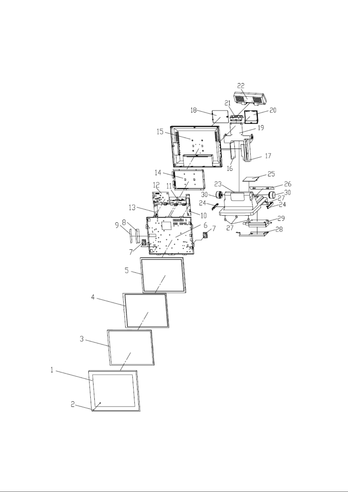
I Part List
A. Explode
Figure 1 Explode of the System
Page 4
- 3 -
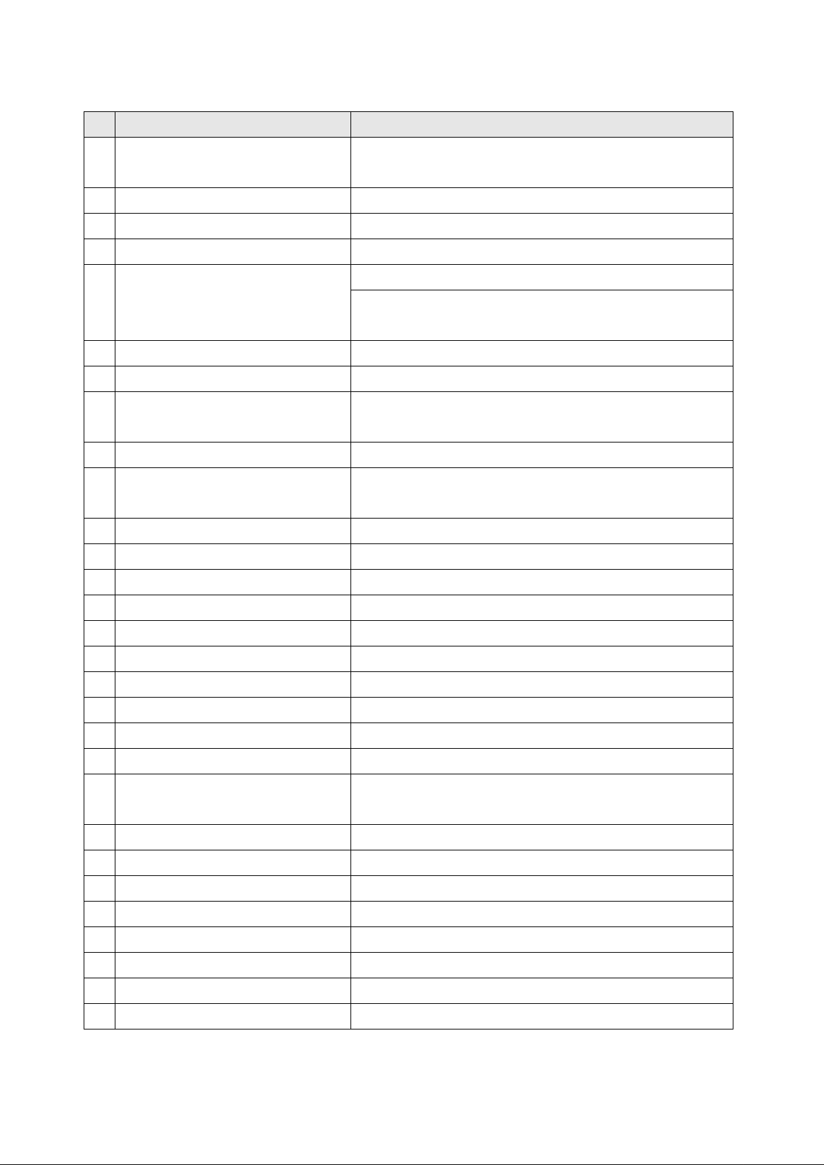
No.
Part
Description
1
FrontBezel
Front Bezel (Black)
Front Bezel (Silver)
2
LED Indicator
Power Indicator
3
Rubber Frame
Touch Panel Rubber
4
Touch Panel
Touch Panel
5
LCD Panel *
15 inch, LED Backlight (PPD-1500)
15 inch, CCFL type (PPD-1500)
17 inch, CCFL type (PPD-1700)
6
Panel Chassis
Metal LCD Panel Chassis
7
Speaker
Speakers x 2
8
OSD Bracket Set (Plate and
Metal Bracket)
OSD Bracket x 1
OSD Plate x 1
9
OSD Control Board
OSD Board
10
Invertor *
LCD Invertor of CCFL type LCD Panel
(PPD-1700/PPD-1500)
11
I/O Board
I/O Board
12
A/D Board
A/D Board (Type A or New Type B)
13
Control Board
Touch Control Board
14
I/O Bracket
Metal I/O Bracket
15
Rear Cover
Rear Cover
16
Side Cover (Right)
Right Cover
17
MSR Kit
MSR Kit (Optional, Black or White Selectable)
18
Rear Cover
Base Rear Cover
19
Hinge Holder
Hinge Holder
20
Holder Cover
Hinge Holder Cover
21
22
Customer Display Set
(Modual and Hinge)
Rear Customer Display Set (Optional)
23
Base
Aluminum Base
24
Side Cover
Base Side Cover
25
Top Cover
Base Top Cover
26
Rear Cover
Base Rear Cover
27
Base Foot
Base Rubber Foot
28
Metal Holder
Power Adaptor Holder
29
Power Adaptor
Power Adaptor
30
Hinge Swivel
Hinge Swivel x 2
PPD-1500 / PPD-1700 SERIES Part List
* Inverter is reserved for some 15 inch/17 inch CCFL type LCD Panels only. Please consult local technical
representative for detailed information.
Page 5

- 4 -
B. Cables & Connectors
Figure 2 Cables
Page 6

- 5 -
No.
Description
Notes
1
Invertor Cable
The Inverter cable is ONLY for CCFL type LCD Panel.
Connect the cable to Inverter and A/D Board.
2
Power Cable
Connect the cable to A/D board and I/O Board.
3
Speakers
Connect the Speakers to the A/D Board.
4
OSD Cable
Connect the cable to A/D Board and OSD Board.
5
LVDS Cable
Connect the cable to A/D Board and LCD Panel
6
Extended LCD Backlight
Cable
This is an extended (auxularily) cable to connect the
LCD panel and connector of Inverter.
As one cable of LCD Panel is connected to the
Inverter, uset the cable to connect the other backlight
connector of Panel to Inverter.
For LED Backlight type LCD Panel:
Use the cable to connect the LCD Panel and A/D
Board.
7
Touch Cable
Connect the cable to Touch Control Board and I/O
Board
8
MSR Cable (Optional)
Connect the Optional MSR Unit to I/O Board.
9
Power Indicator
Connect the LED Indicator to OSD Board.
2
Resistive Type
Touch Panel
7
Figure 3 I/O Board
Figure 4 Resistive Type Touch Control Board
Page 7

- 6 -
2
1 2 5 4 3
1
Figure 5 A/D Board (A)
Figure 6 A/D Board (B)
Page 8

- 7 -
4
9
To LCD Panel
1
To LCD Panel
6
PPD-1500
PPD-1700
1
Figure 7 OSD Board
Figure 8 Invertor Board
Page 9

- 8 -
1. Tilt the LCD panel to the horizontal
level and unplug the cables.
2. Lift the hinge holder cover from the
upper side edges as marked by the
circles and push it down to remove it.
3. Loosen the screw x 2 on the VFD
bracket to remove the VFD.
II System Disassembly
A. Separate the Monitor from the Base
Page 10

- 9 -
4. Loosen the screw x 4 on the hinge
holder and separate the monitor from
the base.
5. Loosen the screw x 7 to remove the
back cover.
B. Disassemble Panel Kit
Page 11

- 10 -
6. Loosen the screw x 6 and the
hex screw x 6 to remove the bracket.
7. Disconnect the cable and loosen the
screw x 2 to remove the MSR kit.
Page 12

- 11 -
8. Disconnect the cable on the A/D
board and loosen the screw x 8 to
remove the speakers.
For Old Type CCFL LCD Panel:
PPD-1500:
9. Disconnect the 3 cables and loosen
the screw x 2 to remove the invertor.
PPD-1700:
Disconnect the 4 cables and loosen the
screw x 2 to remove the invertor.
Page 13

- 12 -
10. Disconnect the 2 cables and loosen
the screw x 3 to remove the I/O
board.
11. Disconnect the 4 cables and loosen
the screw x 4 to remove the A/D
board.
Page 14

- 13 -
12. Disconnect the 2 cables and loosen
the screw x 2 to remove the Touch
control board.
13. Disconnect the 2 cables and loosen
the screw x 4 to remove the OSD
control board.
Page 15

- 14 -
LVDS cable (Right)
of CCFL type LCD Panel
Extended LCD Backlight
Cable (Left) and LVDS cable (Right)
Of LED Backlight type LCD Panel
14. Tear the black tapes and disconnect
the LVDS cable.
Note: LED Backlight type LCD Panel
Disconnect the Extended LCD Backlight
Cable and LVDS cable.
Store them to the secure location.
15. Loosen the screw x 8 to remove the
LCD panel holder.
Page 16

- 15 -
16. Loosen the screw x 4 to remove the
LCD panel holder.
The screw of LCD panel holder (PPD-1700).
17. Remove the front cover.
18. Remove the rubber.
Page 17

- 16 -
19. Turn over the base and loosen the
screw x 2 to remove the power
adaptor.
20. Remove the hinge swivels.
C. Disassemble Base Kit
Page 18

- 17 -
21. Loosen the screw x 6 on both sides
to remove the hinge holder.
Page 19

- 18 -
Date
Version
Note
Description
Feb 02, 2016
Ver. 2.0
New AD Board
Part No removed
New LED Backlight LCD
Panel
BP-PART-MON-2023LA-REV-B-V1
AD Board Abolished
New AD Board
F2270
Add new LED Backlight 15-inch LCD
Panel.
June 22, 2012
Ver. 1.4x
Touch Cable Part No.
revised
CP-CBL-POS-5000-TH-USB
CP-CBL-TM-5000-TH-USB abloshied
Oct 03, 2011
Ver. 1.3
Contents revision
Page 7 no.3 speakers’ part no revised.
Aug 01, 2011
Ver. 1.2
Page 3.part no updated
LC-CAT-TMS150XG1-10TB (15” LCD
Panel)
LC-LG-LM150X08 abolished
Mar 03, 2011
Ver. 1.1
Term amendment
Add 1700 1200 disassemble descriptions
and Parts lists
Aug 08, 2008
Ver. 1.0
First Release
Revision History
 Loading...